WO2021131877A1 - Batterie secondaire et son procédé de production - Google Patents
Batterie secondaire et son procédé de production Download PDFInfo
- Publication number
- WO2021131877A1 WO2021131877A1 PCT/JP2020/046639 JP2020046639W WO2021131877A1 WO 2021131877 A1 WO2021131877 A1 WO 2021131877A1 JP 2020046639 W JP2020046639 W JP 2020046639W WO 2021131877 A1 WO2021131877 A1 WO 2021131877A1
- Authority
- WO
- WIPO (PCT)
- Prior art keywords
- separator
- electrode
- secondary battery
- pole
- adhesive
- Prior art date
Links
- 238000004519 manufacturing process Methods 0.000 title claims description 10
- 239000000853 adhesive Substances 0.000 claims abstract description 202
- 230000001070 adhesive effect Effects 0.000 claims abstract description 202
- 239000000463 material Substances 0.000 claims description 59
- 238000004804 winding Methods 0.000 claims description 24
- 238000000034 method Methods 0.000 claims description 22
- 239000011149 active material Substances 0.000 claims description 12
- 230000010220 ion permeability Effects 0.000 claims description 10
- 238000007731 hot pressing Methods 0.000 claims description 7
- 239000011255 nonaqueous electrolyte Substances 0.000 claims description 6
- 239000010410 layer Substances 0.000 description 91
- 239000011162 core material Substances 0.000 description 73
- 239000008151 electrolyte solution Substances 0.000 description 47
- 239000000203 mixture Substances 0.000 description 44
- 238000007789 sealing Methods 0.000 description 42
- 239000002245 particle Substances 0.000 description 41
- 239000007788 liquid Substances 0.000 description 39
- 229920005989 resin Polymers 0.000 description 16
- 239000011347 resin Substances 0.000 description 16
- 239000011230 binding agent Substances 0.000 description 14
- 229910052751 metal Inorganic materials 0.000 description 14
- 238000003825 pressing Methods 0.000 description 14
- 239000002002 slurry Substances 0.000 description 14
- 239000002184 metal Substances 0.000 description 13
- 238000002347 injection Methods 0.000 description 12
- 239000007924 injection Substances 0.000 description 12
- 230000002093 peripheral effect Effects 0.000 description 12
- OKTJSMMVPCPJKN-UHFFFAOYSA-N Carbon Chemical group [C] OKTJSMMVPCPJKN-UHFFFAOYSA-N 0.000 description 11
- 239000011248 coating agent Substances 0.000 description 11
- 238000000576 coating method Methods 0.000 description 11
- 238000009826 distribution Methods 0.000 description 11
- 238000012360 testing method Methods 0.000 description 11
- -1 Lithium transition metal Chemical class 0.000 description 10
- 150000002484 inorganic compounds Chemical class 0.000 description 10
- 229910010272 inorganic material Inorganic materials 0.000 description 10
- 239000012466 permeate Substances 0.000 description 10
- 229910052782 aluminium Inorganic materials 0.000 description 9
- 239000003792 electrolyte Substances 0.000 description 9
- 230000008569 process Effects 0.000 description 9
- 238000003466 welding Methods 0.000 description 9
- 230000035699 permeability Effects 0.000 description 8
- 239000007774 positive electrode material Substances 0.000 description 8
- 239000012790 adhesive layer Substances 0.000 description 7
- XAGFODPZIPBFFR-UHFFFAOYSA-N aluminium Chemical compound [Al] XAGFODPZIPBFFR-UHFFFAOYSA-N 0.000 description 7
- 239000011888 foil Substances 0.000 description 7
- 239000007789 gas Substances 0.000 description 7
- 239000007773 negative electrode material Substances 0.000 description 7
- 229920000098 polyolefin Polymers 0.000 description 7
- 238000010248 power generation Methods 0.000 description 7
- 239000011241 protective layer Substances 0.000 description 7
- 150000003839 salts Chemical class 0.000 description 7
- 239000010949 copper Substances 0.000 description 6
- 230000000694 effects Effects 0.000 description 6
- 229910002804 graphite Inorganic materials 0.000 description 6
- 239000010439 graphite Substances 0.000 description 6
- 229910000838 Al alloy Inorganic materials 0.000 description 5
- RYGMFSIKBFXOCR-UHFFFAOYSA-N Copper Chemical compound [Cu] RYGMFSIKBFXOCR-UHFFFAOYSA-N 0.000 description 5
- HBBGRARXTFLTSG-UHFFFAOYSA-N Lithium ion Chemical compound [Li+] HBBGRARXTFLTSG-UHFFFAOYSA-N 0.000 description 5
- 239000002033 PVDF binder Substances 0.000 description 5
- 229910052802 copper Inorganic materials 0.000 description 5
- 238000001035 drying Methods 0.000 description 5
- 238000011156 evaluation Methods 0.000 description 5
- 229910052744 lithium Inorganic materials 0.000 description 5
- 229910001416 lithium ion Inorganic materials 0.000 description 5
- 229920002981 polyvinylidene fluoride Polymers 0.000 description 5
- 229920002134 Carboxymethyl cellulose Polymers 0.000 description 4
- SECXISVLQFMRJM-UHFFFAOYSA-N N-Methylpyrrolidone Chemical compound CN1CCCC1=O SECXISVLQFMRJM-UHFFFAOYSA-N 0.000 description 4
- 239000003125 aqueous solvent Substances 0.000 description 4
- 239000002905 metal composite material Substances 0.000 description 4
- 230000004048 modification Effects 0.000 description 4
- 238000012986 modification Methods 0.000 description 4
- 229910052759 nickel Inorganic materials 0.000 description 4
- 229920003048 styrene butadiene rubber Polymers 0.000 description 4
- 229910052723 transition metal Inorganic materials 0.000 description 4
- 239000004925 Acrylic resin Substances 0.000 description 3
- 229920000178 Acrylic resin Polymers 0.000 description 3
- 229910000881 Cu alloy Inorganic materials 0.000 description 3
- 239000004698 Polyethylene Substances 0.000 description 3
- 230000005856 abnormality Effects 0.000 description 3
- 239000006230 acetylene black Substances 0.000 description 3
- PNEYBMLMFCGWSK-UHFFFAOYSA-N aluminium oxide Inorganic materials [O-2].[O-2].[O-2].[Al+3].[Al+3] PNEYBMLMFCGWSK-UHFFFAOYSA-N 0.000 description 3
- 229910001593 boehmite Inorganic materials 0.000 description 3
- 239000002388 carbon-based active material Substances 0.000 description 3
- 239000004020 conductor Substances 0.000 description 3
- 238000006073 displacement reaction Methods 0.000 description 3
- FAHBNUUHRFUEAI-UHFFFAOYSA-M hydroxidooxidoaluminium Chemical compound O[Al]=O FAHBNUUHRFUEAI-UHFFFAOYSA-M 0.000 description 3
- 229910052748 manganese Inorganic materials 0.000 description 3
- 239000011572 manganese Substances 0.000 description 3
- 229920000058 polyacrylate Polymers 0.000 description 3
- 229920002239 polyacrylonitrile Polymers 0.000 description 3
- 229920000573 polyethylene Polymers 0.000 description 3
- 229920001721 polyimide Polymers 0.000 description 3
- KMTRUDSVKNLOMY-UHFFFAOYSA-N Ethylene carbonate Chemical compound O=C1OCCO1 KMTRUDSVKNLOMY-UHFFFAOYSA-N 0.000 description 2
- YCKRFDGAMUMZLT-UHFFFAOYSA-N Fluorine atom Chemical compound [F] YCKRFDGAMUMZLT-UHFFFAOYSA-N 0.000 description 2
- 229910013870 LiPF 6 Inorganic materials 0.000 description 2
- 229920003171 Poly (ethylene oxide) Polymers 0.000 description 2
- 239000004642 Polyimide Substances 0.000 description 2
- 239000004372 Polyvinyl alcohol Substances 0.000 description 2
- VYPSYNLAJGMNEJ-UHFFFAOYSA-N Silicium dioxide Chemical compound O=[Si]=O VYPSYNLAJGMNEJ-UHFFFAOYSA-N 0.000 description 2
- 229920002125 Sokalan® Polymers 0.000 description 2
- 239000002174 Styrene-butadiene Substances 0.000 description 2
- GWEVSGVZZGPLCZ-UHFFFAOYSA-N Titan oxide Chemical compound O=[Ti]=O GWEVSGVZZGPLCZ-UHFFFAOYSA-N 0.000 description 2
- MCMNRKCIXSYSNV-UHFFFAOYSA-N Zirconium dioxide Chemical compound O=[Zr]=O MCMNRKCIXSYSNV-UHFFFAOYSA-N 0.000 description 2
- 229910021383 artificial graphite Inorganic materials 0.000 description 2
- 238000004364 calculation method Methods 0.000 description 2
- 239000001768 carboxy methyl cellulose Substances 0.000 description 2
- 235000010948 carboxy methyl cellulose Nutrition 0.000 description 2
- 239000008112 carboxymethyl-cellulose Substances 0.000 description 2
- 230000008859 change Effects 0.000 description 2
- 238000006243 chemical reaction Methods 0.000 description 2
- 239000011247 coating layer Substances 0.000 description 2
- 239000002131 composite material Substances 0.000 description 2
- 229920001577 copolymer Polymers 0.000 description 2
- 238000010586 diagram Methods 0.000 description 2
- 239000007772 electrode material Substances 0.000 description 2
- 239000000839 emulsion Substances 0.000 description 2
- JBTWLSYIZRCDFO-UHFFFAOYSA-N ethyl methyl carbonate Chemical compound CCOC(=O)OC JBTWLSYIZRCDFO-UHFFFAOYSA-N 0.000 description 2
- 229910052731 fluorine Inorganic materials 0.000 description 2
- 239000011737 fluorine Substances 0.000 description 2
- 230000001771 impaired effect Effects 0.000 description 2
- 239000010954 inorganic particle Substances 0.000 description 2
- 238000010030 laminating Methods 0.000 description 2
- 230000007246 mechanism Effects 0.000 description 2
- 239000000155 melt Substances 0.000 description 2
- 238000002844 melting Methods 0.000 description 2
- 230000008018 melting Effects 0.000 description 2
- 239000012046 mixed solvent Substances 0.000 description 2
- 229920000642 polymer Polymers 0.000 description 2
- 229920005672 polyolefin resin Polymers 0.000 description 2
- 229920001343 polytetrafluoroethylene Polymers 0.000 description 2
- 239000004810 polytetrafluoroethylene Substances 0.000 description 2
- 229920002451 polyvinyl alcohol Polymers 0.000 description 2
- 238000007639 printing Methods 0.000 description 2
- 239000002409 silicon-based active material Substances 0.000 description 2
- 238000007581 slurry coating method Methods 0.000 description 2
- 239000000126 substance Substances 0.000 description 2
- 239000002344 surface layer Substances 0.000 description 2
- XLYOFNOQVPJJNP-UHFFFAOYSA-N water Substances O XLYOFNOQVPJJNP-UHFFFAOYSA-N 0.000 description 2
- UFHFLCQGNIYNRP-UHFFFAOYSA-N Hydrogen Chemical compound [H][H] UFHFLCQGNIYNRP-UHFFFAOYSA-N 0.000 description 1
- 229910001228 Li[Ni1/3Co1/3Mn1/3]O2 (NCM 111) Inorganic materials 0.000 description 1
- WHXSMMKQMYFTQS-UHFFFAOYSA-N Lithium Chemical compound [Li] WHXSMMKQMYFTQS-UHFFFAOYSA-N 0.000 description 1
- 239000004962 Polyamide-imide Substances 0.000 description 1
- 239000004743 Polypropylene Substances 0.000 description 1
- SOXUFMZTHZXOGC-UHFFFAOYSA-N [Li].[Mn].[Co].[Ni] Chemical compound [Li].[Mn].[Co].[Ni] SOXUFMZTHZXOGC-UHFFFAOYSA-N 0.000 description 1
- 150000001408 amides Chemical class 0.000 description 1
- 239000004760 aramid Substances 0.000 description 1
- 229920003235 aromatic polyamide Polymers 0.000 description 1
- 229910052796 boron Inorganic materials 0.000 description 1
- DQXBYHZEEUGOBF-UHFFFAOYSA-N but-3-enoic acid;ethene Chemical compound C=C.OC(=O)CC=C DQXBYHZEEUGOBF-UHFFFAOYSA-N 0.000 description 1
- QHIWVLPBUQWDMQ-UHFFFAOYSA-N butyl prop-2-enoate;methyl 2-methylprop-2-enoate;prop-2-enoic acid Chemical compound OC(=O)C=C.COC(=O)C(C)=C.CCCCOC(=O)C=C QHIWVLPBUQWDMQ-UHFFFAOYSA-N 0.000 description 1
- 229910052799 carbon Inorganic materials 0.000 description 1
- 239000003575 carbonaceous material Substances 0.000 description 1
- 229920002678 cellulose Polymers 0.000 description 1
- 239000001913 cellulose Substances 0.000 description 1
- 239000003795 chemical substances by application Substances 0.000 description 1
- 229910052804 chromium Inorganic materials 0.000 description 1
- 230000000052 comparative effect Effects 0.000 description 1
- 150000001875 compounds Chemical class 0.000 description 1
- 239000006258 conductive agent Substances 0.000 description 1
- 239000011889 copper foil Substances 0.000 description 1
- 238000005520 cutting process Methods 0.000 description 1
- 150000001993 dienes Chemical class 0.000 description 1
- IEJIGPNLZYLLBP-UHFFFAOYSA-N dimethyl carbonate Chemical compound COC(=O)OC IEJIGPNLZYLLBP-UHFFFAOYSA-N 0.000 description 1
- 238000007599 discharging Methods 0.000 description 1
- 239000006185 dispersion Substances 0.000 description 1
- 238000005516 engineering process Methods 0.000 description 1
- 239000003822 epoxy resin Substances 0.000 description 1
- 150000002148 esters Chemical class 0.000 description 1
- 125000002573 ethenylidene group Chemical group [*]=C=C([H])[H] 0.000 description 1
- 150000002170 ethers Chemical class 0.000 description 1
- 239000005038 ethylene vinyl acetate Substances 0.000 description 1
- 230000001747 exhibiting effect Effects 0.000 description 1
- 125000005843 halogen group Chemical group 0.000 description 1
- 150000002367 halogens Chemical group 0.000 description 1
- 229910052739 hydrogen Inorganic materials 0.000 description 1
- 239000001257 hydrogen Substances 0.000 description 1
- 229910052738 indium Inorganic materials 0.000 description 1
- 229910052742 iron Inorganic materials 0.000 description 1
- 238000005304 joining Methods 0.000 description 1
- 239000003273 ketjen black Substances 0.000 description 1
- 238000003475 lamination Methods 0.000 description 1
- 229910003002 lithium salt Inorganic materials 0.000 description 1
- 159000000002 lithium salts Chemical class 0.000 description 1
- 229910052749 magnesium Inorganic materials 0.000 description 1
- 238000005259 measurement Methods 0.000 description 1
- 239000007769 metal material Substances 0.000 description 1
- 239000011325 microbead Substances 0.000 description 1
- 229910021382 natural graphite Inorganic materials 0.000 description 1
- 229910052758 niobium Inorganic materials 0.000 description 1
- 150000002825 nitriles Chemical class 0.000 description 1
- 229920001200 poly(ethylene-vinyl acetate) Polymers 0.000 description 1
- 239000004584 polyacrylic acid Substances 0.000 description 1
- 229920002312 polyamide-imide Polymers 0.000 description 1
- 229920000647 polyepoxide Polymers 0.000 description 1
- 239000009719 polyimide resin Substances 0.000 description 1
- 229920001155 polypropylene Polymers 0.000 description 1
- 229920002635 polyurethane Polymers 0.000 description 1
- 239000004814 polyurethane Substances 0.000 description 1
- 239000011148 porous material Substances 0.000 description 1
- 238000005096 rolling process Methods 0.000 description 1
- 239000000377 silicon dioxide Substances 0.000 description 1
- 238000002791 soaking Methods 0.000 description 1
- 239000002904 solvent Substances 0.000 description 1
- 239000012798 spherical particle Substances 0.000 description 1
- 229910052715 tantalum Inorganic materials 0.000 description 1
- 229920002803 thermoplastic polyurethane Polymers 0.000 description 1
- 229910052718 tin Inorganic materials 0.000 description 1
- 229910052719 titanium Inorganic materials 0.000 description 1
- 238000012546 transfer Methods 0.000 description 1
- 229910000314 transition metal oxide Inorganic materials 0.000 description 1
- 229910052721 tungsten Inorganic materials 0.000 description 1
- 229910052720 vanadium Inorganic materials 0.000 description 1
- 229910052725 zinc Inorganic materials 0.000 description 1
- 229910052726 zirconium Inorganic materials 0.000 description 1
- 239000004711 α-olefin Substances 0.000 description 1
Images


Classifications
-
- H—ELECTRICITY
- H01—ELECTRIC ELEMENTS
- H01M—PROCESSES OR MEANS, e.g. BATTERIES, FOR THE DIRECT CONVERSION OF CHEMICAL ENERGY INTO ELECTRICAL ENERGY
- H01M10/00—Secondary cells; Manufacture thereof
- H01M10/05—Accumulators with non-aqueous electrolyte
- H01M10/058—Construction or manufacture
- H01M10/0585—Construction or manufacture of accumulators having only flat construction elements, i.e. flat positive electrodes, flat negative electrodes and flat separators
-
- H—ELECTRICITY
- H01—ELECTRIC ELEMENTS
- H01M—PROCESSES OR MEANS, e.g. BATTERIES, FOR THE DIRECT CONVERSION OF CHEMICAL ENERGY INTO ELECTRICAL ENERGY
- H01M10/00—Secondary cells; Manufacture thereof
- H01M10/05—Accumulators with non-aqueous electrolyte
- H01M10/058—Construction or manufacture
- H01M10/0587—Construction or manufacture of accumulators having only wound construction elements, i.e. wound positive electrodes, wound negative electrodes and wound separators
-
- H—ELECTRICITY
- H01—ELECTRIC ELEMENTS
- H01M—PROCESSES OR MEANS, e.g. BATTERIES, FOR THE DIRECT CONVERSION OF CHEMICAL ENERGY INTO ELECTRICAL ENERGY
- H01M10/00—Secondary cells; Manufacture thereof
- H01M10/05—Accumulators with non-aqueous electrolyte
- H01M10/052—Li-accumulators
-
- H—ELECTRICITY
- H01—ELECTRIC ELEMENTS
- H01M—PROCESSES OR MEANS, e.g. BATTERIES, FOR THE DIRECT CONVERSION OF CHEMICAL ENERGY INTO ELECTRICAL ENERGY
- H01M50/00—Constructional details or processes of manufacture of the non-active parts of electrochemical cells other than fuel cells, e.g. hybrid cells
- H01M50/40—Separators; Membranes; Diaphragms; Spacing elements inside cells
- H01M50/46—Separators, membranes or diaphragms characterised by their combination with electrodes
- H01M50/461—Separators, membranes or diaphragms characterised by their combination with electrodes with adhesive layers between electrodes and separators
-
- H—ELECTRICITY
- H01—ELECTRIC ELEMENTS
- H01M—PROCESSES OR MEANS, e.g. BATTERIES, FOR THE DIRECT CONVERSION OF CHEMICAL ENERGY INTO ELECTRICAL ENERGY
- H01M10/00—Secondary cells; Manufacture thereof
- H01M10/05—Accumulators with non-aqueous electrolyte
- H01M10/052—Li-accumulators
- H01M10/0525—Rocking-chair batteries, i.e. batteries with lithium insertion or intercalation in both electrodes; Lithium-ion batteries
-
- H—ELECTRICITY
- H01—ELECTRIC ELEMENTS
- H01M—PROCESSES OR MEANS, e.g. BATTERIES, FOR THE DIRECT CONVERSION OF CHEMICAL ENERGY INTO ELECTRICAL ENERGY
- H01M10/00—Secondary cells; Manufacture thereof
- H01M10/05—Accumulators with non-aqueous electrolyte
- H01M10/056—Accumulators with non-aqueous electrolyte characterised by the materials used as electrolytes, e.g. mixed inorganic/organic electrolytes
- H01M10/0561—Accumulators with non-aqueous electrolyte characterised by the materials used as electrolytes, e.g. mixed inorganic/organic electrolytes the electrolyte being constituted of inorganic materials only
- H01M10/0563—Liquid materials, e.g. for Li-SOCl2 cells
-
- H—ELECTRICITY
- H01—ELECTRIC ELEMENTS
- H01M—PROCESSES OR MEANS, e.g. BATTERIES, FOR THE DIRECT CONVERSION OF CHEMICAL ENERGY INTO ELECTRICAL ENERGY
- H01M10/00—Secondary cells; Manufacture thereof
- H01M10/05—Accumulators with non-aqueous electrolyte
- H01M10/056—Accumulators with non-aqueous electrolyte characterised by the materials used as electrolytes, e.g. mixed inorganic/organic electrolytes
- H01M10/0564—Accumulators with non-aqueous electrolyte characterised by the materials used as electrolytes, e.g. mixed inorganic/organic electrolytes the electrolyte being constituted of organic materials only
- H01M10/0566—Liquid materials
-
- H—ELECTRICITY
- H01—ELECTRIC ELEMENTS
- H01M—PROCESSES OR MEANS, e.g. BATTERIES, FOR THE DIRECT CONVERSION OF CHEMICAL ENERGY INTO ELECTRICAL ENERGY
- H01M4/00—Electrodes
- H01M4/02—Electrodes composed of, or comprising, active material
- H01M4/04—Processes of manufacture in general
- H01M4/0402—Methods of deposition of the material
- H01M4/0404—Methods of deposition of the material by coating on electrode collectors
-
- H—ELECTRICITY
- H01—ELECTRIC ELEMENTS
- H01M—PROCESSES OR MEANS, e.g. BATTERIES, FOR THE DIRECT CONVERSION OF CHEMICAL ENERGY INTO ELECTRICAL ENERGY
- H01M4/00—Electrodes
- H01M4/02—Electrodes composed of, or comprising, active material
- H01M4/13—Electrodes for accumulators with non-aqueous electrolyte, e.g. for lithium-accumulators; Processes of manufacture thereof
-
- Y—GENERAL TAGGING OF NEW TECHNOLOGICAL DEVELOPMENTS; GENERAL TAGGING OF CROSS-SECTIONAL TECHNOLOGIES SPANNING OVER SEVERAL SECTIONS OF THE IPC; TECHNICAL SUBJECTS COVERED BY FORMER USPC CROSS-REFERENCE ART COLLECTIONS [XRACs] AND DIGESTS
- Y02—TECHNOLOGIES OR APPLICATIONS FOR MITIGATION OR ADAPTATION AGAINST CLIMATE CHANGE
- Y02E—REDUCTION OF GREENHOUSE GAS [GHG] EMISSIONS, RELATED TO ENERGY GENERATION, TRANSMISSION OR DISTRIBUTION
- Y02E60/00—Enabling technologies; Technologies with a potential or indirect contribution to GHG emissions mitigation
- Y02E60/10—Energy storage using batteries
-
- Y—GENERAL TAGGING OF NEW TECHNOLOGICAL DEVELOPMENTS; GENERAL TAGGING OF CROSS-SECTIONAL TECHNOLOGIES SPANNING OVER SEVERAL SECTIONS OF THE IPC; TECHNICAL SUBJECTS COVERED BY FORMER USPC CROSS-REFERENCE ART COLLECTIONS [XRACs] AND DIGESTS
- Y02—TECHNOLOGIES OR APPLICATIONS FOR MITIGATION OR ADAPTATION AGAINST CLIMATE CHANGE
- Y02P—CLIMATE CHANGE MITIGATION TECHNOLOGIES IN THE PRODUCTION OR PROCESSING OF GOODS
- Y02P70/00—Climate change mitigation technologies in the production process for final industrial or consumer products
- Y02P70/50—Manufacturing or production processes characterised by the final manufactured product
Definitions
- This disclosure relates to a secondary battery and a method for manufacturing the secondary battery.
- Patent Document 1 a flat electrode body in which a positive electrode plate and a negative electrode plate are laminated in a plurality of layers via a separator is inserted into the exterior body.
- the positive electrode plate has positive electrode active material mixture layers provided on both sides of the positive electrode core body
- the negative electrode plate has negative electrode active material mixture layers provided on both sides of the negative electrode core body.
- the positive electrode active material and the negative electrode active material each have a structure capable of inserting and removing lithium ions.
- the separator is a porous substance that allows lithium ions to permeate, while preventing a short circuit due to electrical contact between the positive electrode plate and the negative electrode plate.
- the positive electrode plate and the negative electrode plate are electrically connected to the current collector plate and inserted into the exterior body.
- the exterior body is sealed after injecting the electrolytic solution.
- an adhesive layer is provided on the surface of the separator so that the separator shrinks and direct contact between the positive and negative electrodes does not occur, and thermocompression bonding is performed to bond the positive electrode plate / separator and the negative electrode plate / separator. I'm letting you.
- the inventors of the present application have discovered the following new problems. Specifically, in order to facilitate the handling of the electrode body, suppress the misalignment of the electrode plates in the laminated body, and particularly suppress the misalignment of the electrode plates when the laminated body is inserted into the sealing body, the electrodes When an adhesive material is provided between the separator and the separator, the liquid circulation property (liquid permeability) of the electrolytic solution depends on the strength of the adhesive.
- the adhesive force when the adhesive force is strong, the density of the adhesive material becomes high and the gap between the electrode and the separator becomes narrow, so that the liquid circulation property of the electrolytic solution is likely to be impaired.
- the adhesive force is weak, the liquid circulation property is good, but the handleability of the electrode body is impaired, and the position of the separator with respect to the electrode tends to shift.
- the liquid circulation property will be described. Since the electrolytic solution permeates from the end of the electrode body in the stacking direction, the electrode liquid permeates as the distance from the electrode located at the end of the electrode body in the stacking direction increases in the stacking direction. It is difficult to spread the electrolytic solution over the entire electrode surface. That is, the electrolytic solution becomes less likely to permeate toward the center of the laminate. This problem becomes particularly prominent in a large-capacity secondary battery having a large electrode area and requiring a large amount of electrolyte between each electrode, and in a large-capacity secondary battery, the entire surface of the electrode body is sufficient. It takes time to distribute the electrolyte. Therefore, when an adhesive is used, there is a risk of causing a particularly large decrease in productivity in a large-capacity secondary battery.
- the adhesive needs to have the minimum adhesive force to achieve this purpose.
- control of adhesive force can have a great impact on production tact.
- an adhesive material whose adhesive force depends at least on heat and pressure is used.
- the secondary battery according to one aspect of the present disclosure includes a plurality of first poles having a first pole active material arranged on the first pole core body and the first pole core body, and the second pole core body and the second pole.
- An adhesive disposed between a plurality of second poles having a second pole active material arranged on a polar core body, one or more separators, at least one side surface in the thickness direction of the separator, and the first pole.
- a plurality of first poles and a plurality of second poles are alternately laminated via a separator, and a laminated body including a plurality of first poles and a plurality of second poles has 10 or more first poles.
- the adhesive strength between the first pole of the outermost layer and the separator is A0 [N / m], and the adhesive strength between the first pole located in the center of the laminated body and the separator is A1 [N / m].
- A1 / A0 is 0.1 or more and less than 0.9.
- the first electrode may be a positive electrode or a negative electrode.
- the laminated body is composed of, for example, an electrode group or an electrode body, and when the number of laminated first poles is an odd number, only one central first pole in the stacking direction exists, but the first pole When the number of stacked poles is even, there are two central first poles in the stacking direction. Further, there are two first poles of the outermost layer.
- the value of A1 / A0 is the smallest, and the value of A1 / A0 when the first pole of the outermost layer and the first pole in the center in the stacking direction are selected is , 0.1 or more.
- the secondary battery according to another aspect of the present disclosure includes a band-shaped first pole having a first pole active material arranged on the first pole core body and the first pole core body, a second pole core body, and the second pole core body.
- a band-shaped second pole having a second pole active material arranged on the second pole core body comprises a winding body in which five or more turns are wound via a band-shaped separator, and the winding body is in the separator. It has an adhesive arranged between at least one side surface in the thickness direction and the first pole, and the adhesive force between the first pole located on the outermost circumference and the separator is A0 [N / m], and the innermost circumference.
- A1 / A0 is 0.1 or more and less than 0.9.
- the first electrode may be a positive electrode or a negative electrode.
- a local region (a pair of presses) in which the press plate for pressing the electrode body flatly and the electrode are parallel to each other
- the region sandwiched between the plates) has a structure in which the positive electrode, the negative electrode, and the separator are laminated in a state where the separator is arranged between the positive electrode and the negative electrode. Therefore, even when the secondary battery has a wound electrode body, the local region where the press plate and the electrode are parallel can be considered as a laminated body, and in that case, on the innermost peripheral side.
- the position separator can be considered as the inner (center side) separator of the laminate, and the separator located on the outermost peripheral side can be considered as the outer separator of the laminate.
- the secondary battery according to the present disclosure it is easy to shorten the cycle time while ensuring the necessary adhesive force inside the laminate, and further, it is easy to improve the liquid circulation property of the electrolytic solution inside the laminate. .. Further, according to the secondary battery according to the present disclosure, it is easy to manufacture such a secondary battery.
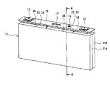
- FIG. 1 is a perspective view of a square secondary battery according to an embodiment of the present disclosure.
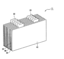
- FIG. 2 is a perspective view of an electrode body and a sealing plate constituting the square secondary battery.
- FIG. 3 is an exploded perspective view of the electrode body of the square secondary battery.
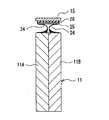
- FIG. 4 is a diagram schematically showing a cross section taken along line AA of FIG.
- FIG. 5 is an enlarged schematic cross-sectional view when a part of the outer side of the first electrode group in the stacking direction is cut by a plane substantially orthogonal to the height direction of the square secondary battery, and a part of the separator and the positive electrode are shown. It is an enlarged schematic cross-sectional view including a part and the adhesive part which is adhering in the adhesive described below.
- FIG. 1 is a perspective view of a square secondary battery according to an embodiment of the present disclosure.
- FIG. 2 is a perspective view of an electrode body and a sealing plate constituting the square secondary battery.
- FIG. 3 is an exploded perspective view
- FIG. 6 is a schematic view showing the relationship between the position in the stacking direction and the adhesive force between the electrode and the separator in the laminated electrode body.
- FIG. 7 is an enlarged schematic cross-sectional view when a part of the inside of the first electrode group in the stacking direction is cut in a plane substantially orthogonal to the height direction, and similarly to FIG. 5, the adhesive exerts adhesive strength. It is an enlarged schematic cross-sectional view which is omitted from the drawing of the part not shown.
- FIG. 8 is a plan view of the wound type square secondary battery of another embodiment.
- FIG. 10 (b) is a sectional view taken along line BB of FIG. 10 (a)
- FIG. 10 (c) is a sectional view taken along line BB. It is sectional drawing of the CC line of (a).
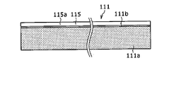
- FIG. 11A is a plan view of the positive electrode included in the wound square secondary battery.
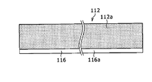
- FIG. 11B is a plan view of the negative electrode included in the wound square secondary battery.
- FIG. 12 is a perspective view showing the winding end end side of the flat wound electrode body included in the wound square secondary battery.
- FIG. 13 is a schematic view corresponding to FIG. 6 in the wound electrode body.
- the description of "numerical value A to numerical value B” means “numerical value A or more and numerical value B or less”.
- the height direction of the outer cans 14 and 140 is defined as the “vertical direction” of the secondary batteries 10 and 110, the sealing plate 15 side and 123 side are “top”, and the bottom side of the outer cans 14 and 140. Is “below”. Further, the direction along the longitudinal direction of the sealing plates 15 and 123 is defined as the "lateral direction" of the secondary batteries 10 and 110.
- the laminated body is composed of, for example, an electrode group or an electrode body, but the first pole is laminated.
- the number is odd, there is only one central first pole in the stacking direction, but when the number of stacked first poles is even, there are two central first poles in the stacking direction. .. Further, there are two first poles of the outermost layer in the stacking direction.
- A1 / A0 When the above A1 / A0 is 0.1 or more, the value of A1 / A0 is the smallest, and the value of A1 / A0 when the first pole of the outermost layer and the first pole in the center in the stacking direction are selected is , 0.1 or more. Similarly, when A1 / A0 is 0.9 or less, A1 when the first pole of the outermost layer and the first pole in the center in the stacking direction, which have the largest value of A1 / A0, are selected. It means that the value of / A0 is 0.9 or less.
- A1 / A0 when the wording that A1 / A0 is a or more is used, it means that the first pole of the outermost layer, which has the smallest value of A1 / A0, and the first pole in the center of the stacking direction are selected. It is assumed that the value of A1 / A0 is equal to or greater than a. Further, when the wording that A1 / A0 is b or less is used, it is when the first pole of the outermost layer and the first pole in the center in the stacking direction, which have the largest value of A1 / A0, are selected. It is assumed that the value of A1 / A0 of is not less than or equal to b.
- the adhesive force at the center of the laminated body (for example, the electrode group or the electrode body) is referred to, when it means the lower limit, the lower one of the one or two first poles at the center is adhered. It will refer to the adhesive force of the first electrode having the force.
- the adhesive strength at the center of the laminated body (for example, the electrode group or the electrode body) is referred to, when it means the upper limit, the higher one of the one or two first poles at the center is adhered. It will refer to the adhesive force of the first electrode having the force.
- FIG. 1 is a perspective view of a square secondary battery 10 according to an embodiment of the present disclosure
- FIG. 2 is a perspective view of an electrode body 11 and a sealing plate 15 constituting the square secondary battery 10 (the outer can 14 is removed). It is a figure which shows the state.
- the square secondary battery (hereinafter, simply referred to as a secondary battery) 10 includes a square container including an outer can 14 and a sealing plate 15 as an outer body, and the outer body includes this. Not limited.
- the secondary battery 10 includes an electrode body 11, an electrolyte, a bottomed tubular outer can 14 in which the electrode body 11 and the electrolyte are housed, a positive electrode terminal 12, and a negative electrode terminal 13. Is attached, and is provided with a sealing plate 15 that closes the opening of the outer can 14.
- the electrode body 11 has a structure in which the positive electrode 20 and the negative electrode 30 are alternately laminated via the separator 40.
- the outer can 14 is a flat, substantially rectangular parallelepiped-shaped metal square container having one end opened in the height direction.
- the outer can 14 and the sealing plate 15 are made of, for example, a metal material containing aluminum as a main component.
- the electrolyte may be an aqueous electrolyte, but is preferably a non-aqueous electrolyte, and in the present embodiment, a non-aqueous electrolyte solution is used.
- the non-aqueous electrolyte solution contains, for example, a non-aqueous solvent and an electrolyte salt dissolved in the non-aqueous solvent.
- the non-aqueous solvent for example, esters, ethers, nitriles, amides, and a mixed solvent of two or more of these may be used.
- the non-aqueous solvent may contain a halogen substituent in which at least a part of hydrogen in these solvents is substituted with a halogen atom such as fluorine.
- the electrolyte salt for example, a lithium salt such as LiPF 6 is used.
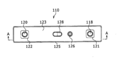
- the sealing plate 15 has an elongated rectangular shape, and a positive electrode terminal 12 is arranged on one end side in the longitudinal direction, and a negative electrode terminal 13 is arranged on the other end side in the longitudinal direction of the sealing plate 15.
- the positive electrode terminal 12 and the negative electrode terminal 13 are external connection terminals that are electrically connected to another secondary battery 10 or a load, and are attached to the sealing plate 15 via an insulating member.
- the positive electrode 20 includes a positive electrode tab 23 electrically connected to the positive electrode terminal 12, and the negative electrode 30 includes a negative electrode tab 33 electrically connected to the negative electrode terminal 13.
- the positive electrode terminal 12 is electrically connected to the positive electrode tab group 24 in which a plurality of positive electrode tabs 23 are laminated via the positive electrode current collector plate 25, and the negative electrode terminal 13 is connected to the negative electrode terminal 13 via the negative electrode current collector plate 35.
- the tabs 33 are electrically connected to the negative electrode tab group 34 formed by stacking the tabs 33.
- the sealing plate 15 is provided with a current cutoff device 18 as a functional component for cutting the current path when an abnormality occurs in the battery.
- the functional component is, for example, a component that functions as a safety device or a control device for the secondary battery 10.
- the functional components are arranged close to the positive electrode terminal 12 or the negative electrode terminal 13 on the inner surface of the sealing plate 15.
- the current cutoff device 18 is attached to the positive electrode terminal 12 and is arranged inside the positive electrode terminal 12.
- the current cutoff device 18 is a pressure sensing type safety device that cuts off the current path when an abnormality occurs in the secondary battery 10 and the internal pressure of the outer can 14 rises beyond a predetermined pressure.
- the current cutoff device 18 is arranged, for example, between the positive electrode terminal 12 and the positive electrode current collector plate 25, and is electrically connected to the positive electrode terminal 12 and the positive electrode current collector plate 25 during normal use.
- the structure of the current cutoff device 18 is not particularly limited, but as an example, when the internal pressure rises, it reverses in the direction away from the positive electrode current collector plate 25 to disconnect the electrical connection between the positive electrode current collector plate 25 and the positive electrode terminal 12 and the positive electrode. Examples thereof include an apparatus including an inversion plate that cuts off the current path of the current collector plate 25.
- the sealing plate 15 is provided with a liquid injection unit 16 for injecting a non-aqueous electrolytic solution and a gas discharge valve 17 for opening and discharging gas when an abnormality occurs in the battery.
- the gas discharge valve 17 is arranged at the center of the sealing plate 15 in the longitudinal direction, and the liquid injection part 16 is arranged between the positive electrode terminal 12 and the gas discharge valve 17.
- the electrode body 11 is divided into a first electrode group 11A and a second electrode group 11B.
- the electrode groups 11A and 11B have, for example, the same laminated structure and dimensions, and are arranged in a laminated manner in the thickness direction of the electrode body 11.
- a positive electrode tab group 24 composed of a plurality of positive electrode tabs 23 and a negative electrode tab group 34 composed of a plurality of negative electrode tabs 33 are formed at the upper end of each electrode group, and are connected to each current collector plate of the sealing plate 15.
- the outer peripheral surfaces of the electrode groups 11A and 11B are covered with a separator 40, and the electrode groups 11A and 11B are configured so that independent battery reactions occur.
- FIG. 3 is an exploded perspective view of the electrode body 11.
- the electrode body 11 includes a plurality of positive electrodes 20 and a plurality of negative electrodes 30.
- the electrode groups 11A and 11B constituting the electrode body 11 include, for example, one more negative electrode 30 than the positive electrode 20, and the negative electrodes 30 are arranged on both sides of the electrode groups 11A and 11B in the thickness direction.
- FIG. 3 shows a plurality of separators 40 arranged one by one between the positive electrode 20 and the negative electrode 30, one separator 40 may be included in each of the electrode groups 11A and 11B. In this case, the long separator 40 is folded in ninety-nine and arranged between the positive electrode 20 and the negative electrode 30.
- each of the electrode groups 11A and 11B contains an adhesive and is produced by using a heat pressing step. More specifically, in each of the electrode groups 11A and 11B, a laminated body in which a plurality of positive electrodes 20 and a plurality of negative electrodes 30 are alternately laminated one by one via a separator 40 is laminated using a pair of hot plates. It is produced by applying heat and pressure to the laminate so that at least a part of the adhesive exhibits adhesive strength.
- the electrode body 11 includes an electrode group 11A and an electrode group 11B thus produced, and is a laminated electrode body in which a plurality of positive electrodes 20 and a plurality of negative electrodes 30 are alternately laminated one by one via a separator 40.
- the positive electrode 20 includes a positive electrode tab 23 projecting upward
- the negative electrode 30 includes a negative electrode tab 33 projecting upward.
- the positive electrode 20 and the negative electrode 30 are laminated so that the tabs face the same direction.
- the positive electrode tab 23 is located on one end side in the lateral direction of the electrode body 11
- the negative electrode tab 33 is located on the other end side in the lateral direction of the electrode body 11, and a plurality of positive electrode tabs 23 are arranged in the thickness direction of the electrode body 11.
- a plurality of negative electrode tabs 33 are laminated and arranged so as to be arranged in the thickness direction of the electrode body 11.
- the positive electrode 20 has a positive electrode core body and a positive electrode mixture layer provided on the surface of the positive electrode core body.
- a foil of a metal stable in the potential range of the positive electrode 20 such as aluminum or an aluminum alloy, a film in which the metal is arranged on the surface layer, or the like can be used.
- the positive electrode mixture layer contains a positive electrode active material, a conductive material, and a binder, and is preferably provided on both sides of the positive electrode core body.
- a positive electrode mixture slurry containing a positive electrode active material, a conductive material, a binder, and the like is applied onto the positive electrode core, the coating film is dried, and then compressed to form the positive electrode mixture layer into the positive electrode core. It can be produced by forming it on both sides of the body.
- the positive electrode 20 has a structure in which a positive electrode mixture layer composed of a positive electrode mixture is arranged over the entire surface of the positive electrode core body excluding the positive electrode tab 23 (hereinafter referred to as a “base”).
- the thickness of the positive electrode core is, for example, 5 ⁇ m to 20 ⁇ m, preferably 8 ⁇ m to 15 ⁇ m.
- the base of the positive electrode core has a quadrangular shape in front view, and the positive electrode tab 23 projects from one side of the quadrangle.
- one metal foil is processed to obtain a positive electrode core body in which a base portion and a positive electrode tab 23 are integrally molded.
- Lithium transition metal composite oxide is used as the positive electrode active material.
- Metallic elements contained in the lithium transition metal composite oxide include Ni, Co, Mn, Al, B, Mg, Ti, V, Cr, Fe, Cu, Zn, Ga, Sr, Zr, Nb, In and Sn. , Ta, W and the like. Above all, it is preferable to contain at least one of Ni, Co and Mn.
- suitable composite oxides include lithium transition metal composite oxides containing Ni, Co and Mn, and lithium transition metal composite oxides containing Ni, Co and Al.
- Examples of the conductive material contained in the positive electrode mixture layer include carbon materials such as carbon black, acetylene black, ketjen black, and graphite.
- Examples of the binder contained in the positive electrode mixture layer include fluororesins such as polytetrafluoroethylene (PTFE) and polyvinylidene fluoride (PVdF), polyacrylonitrile (PAN), polyimide resins, acrylic resins, and polyolefin resins. .. Further, these resins may be used in combination with a cellulose derivative such as carboxymethyl cellulose (CMC) or a salt thereof, polyethylene oxide (PEO), or the like.
- CMC carboxymethyl cellulose
- PEO polyethylene oxide
- the negative electrode 30 has a negative electrode core body and a negative electrode mixture layer provided on the surface of the negative electrode core body and composed of a negative electrode mixture.
- a metal foil such as copper that is stable in the potential range of the negative electrode 30, a film on which the metal is arranged on the surface layer, or the like can be used.
- the negative electrode mixture layer contains a negative electrode active material and a binder, and is preferably provided on both sides of the negative electrode core body.
- a negative electrode mixture slurry containing a negative electrode active material, a binder, and the like is applied to the surface of the negative electrode core, the coating film is dried, and then compressed to form a negative electrode mixture layer of the negative electrode core. It can be produced by forming it on both sides.
- the negative electrode 30 has a structure in which a negative electrode mixture layer is formed on the entire surface of the negative electrode core body except for the negative electrode tab 33.
- the thickness of the negative electrode core is, for example, 3 ⁇ m to 15 ⁇ m, preferably 5 ⁇ m to 10 ⁇ m.
- the base of the negative electrode core has a quadrangular shape in front view, and the negative electrode tab 33 projects from one side of the quadrangle.
- one metal foil is processed to obtain a negative electrode core body in which a base portion and a negative electrode tab 33 are integrally molded.
- the negative electrode active material for example, a carbon-based active material that reversibly occludes and releases lithium ions is used.
- Suitable carbon-based active materials are natural graphite such as scaly graphite, massive graphite, earthy graphite, and graphite such as artificial graphite such as massive artificial graphite (MAG) and graphitized mesophase carbon microbeads (MCMB).
- a Si-based active material composed of at least one of Si and a Si-containing compound may be used, or a carbon-based active material and a Si-based active material may be used in combination.
- the binder contained in the negative electrode mixture layer fluororesin, PAN, polyimide, acrylic resin, polyolefin or the like can be used as in the case of the positive electrode 20, but styrene-butadiene rubber (SBR) is used. Is preferable.
- the negative electrode mixture layer preferably further contains CMC or a salt thereof, polyacrylic acid (PAA) or a salt thereof, polyvinyl alcohol (PVA) and the like. Above all, it is preferable to use SBR in combination with CMC or a salt thereof, PAA or a salt thereof.
- FIG. 4 is a diagram schematically showing a cross section taken along line AA of FIG.
- the electrode body 11 has a positive electrode tab group 24 in which a plurality of positive electrode tabs 23 are laminated, and a negative electrode tab group 34 in which a plurality of negative electrode tabs 33 are laminated.
- the positive electrode tab group 24 is formed by superimposing a plurality of positive electrode tabs 23 in the stacking direction of the electrodes, one for each of the electrode groups 11A and 11B.
- the negative electrode tab group 34 is formed by superimposing a plurality of negative electrode tabs 33 in the stacking direction of the electrodes, one for each of the electrode groups 11A and 11B.
- the positive electrode tab group 24 is joined to the positive electrode current collector plate 25 attached to the inner surface (lower surface) of the sealing plate 15 by welding or the like.
- the positive electrode current collector plate 25 is a plate-shaped conductive member that is electrically connected to the positive electrode terminal 12 via the current cutoff device 18.
- An insulating member 26 is interposed between the sealing plate 15 and the positive electrode current collector plate 25 to prevent contact between the two members.
- the negative electrode tab group 34 is joined to the negative electrode current collector plate 35 attached to the inner surface of the sealing plate 15 via an insulating member by welding or the like.
- the shapes of the positive electrode tab group 24 and the negative electrode tab group 34 are not particularly limited as long as they function as conductive paths connecting the electrode body 11 and each terminal.
- the plurality of positive electrode tabs 23 and the plurality of negative electrode tabs 33 of the electrode group 11A are laminated in a state of being curved from the outside to the inside of the secondary battery 10, respectively, and the cross-sectional view is substantially U.
- a character-shaped positive electrode tab group 24 and a negative electrode tab group 34 are formed.
- the electrode group 11B also has a tab group having a substantially U-shaped cross section. Each tab group may have a U-shape curved from the inside to the outside of the secondary battery 10. Then, as shown in FIG.
- the cross-sectional shape of the tab group of the other electrode group is approximately the boundary line of the electrode group with respect to the cross-sectional shape of the tab group of one electrode group. They may be arranged symmetrically.
- the positive electrode tab group 24 may be welded to the upper surface of the positive electrode current collector plate 25 facing the sealing plate 15 side, but is preferably welded to the lower surface of the positive electrode current collector plate 25. In the present embodiment, both the positive electrode tab group 24 and the negative electrode tab group 34 are welded to the lower surface of the current collector plate. For example, the positive electrode tab group 24 is welded to the lower surface of the positive electrode current collector plate 25 and the negative electrode tabs. Group 34 may be welded to the upper surface of the negative electrode current collector plate 35. Further, in the present embodiment, the case where the electrode body 11 includes the divided first electrode group 11A and the second electrode group 11B has been described, but the electrode body has one undivided electrode group. You may.
- the sealing plate 15 After welding the electrode body 11 to the sealing plate 15, for example, the sealing plate 15 is fitted into the opening of the outer can 14, and the sealing plate 15 to which the electrode body 11 is attached and the outer can 14 are fitted. Laser weld the joint. After that, the non-aqueous electrolytic solution is injected into the outer can 14 using the liquid injection unit 16, and then the liquid injection unit 16 is sealed with a blind rivet to form the secondary battery 10.
- FIG. 5 is an enlarged schematic cross-sectional view of the first electrode group 11A (hereinafter, simply referred to as the electrode group 11A) when a part of the outside in the stacking direction is cut along a plane substantially orthogonal to the height direction. It is an enlarged schematic cross-sectional view including a part of 40, a part of a positive electrode 20, and an adhesive portion (a portion exhibiting adhesive force in the adhesive) 50a that is adhered in the adhesive 50 described below. Paradoxically, FIG. 5 is an enlarged schematic cross-sectional view of the adhesive 50 in which the portion that does not contribute to adhesion is omitted.
- the separator 40 has a resin base material (for example, a polyolefin base material) 40a and a heat-resistant layer provided on one side surface of the base material 40a in the thickness direction by an existing method such as coating. It has 40b.
- the heat-resistant layer 40b may be provided on both one side surface and the other side surface in the thickness direction of the base material 40a, or the separator 40 may not have a heat-resistant layer at all.
- the electrode group 11A further includes an adhesive 50.
- the adhesive 50 is provided with the heat-resistant layer 40b on the entire surface of one side surface of the base material 40a in the thickness direction, and then the entire surface of one side surface of the separator 40 on which the heat-resistant layer 40b is not provided. And, it is applied by arranging a plurality of dot-shaped adhesives (dot-shaped portions) by printing or the like so that the area density is substantially constant over the entire area of the other side surface of the separator 40 provided with the heat-resistant layer 40b. ..
- the amount of each dot-shaped adhesive 50 is substantially the same.
- the number density of the dot-shaped adhesive 50 is substantially constant over the entire area of one side surface and the entire area of the other side surface of the separator 40.
- the coating form of the adhesive 50 may not be a dot-shaped coating form, but may be a coating form on the entire surface of the separator. That is, the adhesive may be applied to at least one of one side surface and the other side surface of the separator so that the area density is substantially constant, and an adhesive layer may be provided on at least one side surface of the separator.
- the adhesive 50 is located between the base material 40a and the electrode (at least one of the positive electrode 20 and the negative electrode 30), and the adhesive 50 is placed on the base material 40a.
- a heat-resistant layer (slurry coating layer) 40b containing alumina particles as a main component may be provided, and the adhesive 50 may be coated on the heat-resistant layer (slurry coating layer) 40b.
- the resin-made porous base material 40a functions as a separator 40 by itself.
- a porous film having ion permeability and insulating property is used as the base material 40a.
- the thickness of the base material 40a is, for example, 1 ⁇ m to 20 ⁇ m.
- the material of the base material 40a include olefin resins such as polyethylene, polypropylene, a copolymer of ethylene-propylene, ethylene, propylene, and a copolymer with other ⁇ -olefins.
- the melting point of the resin base material is generally 200 ° C. or lower.
- the porous film constituting the base material 40a has many pores for allowing lithium ions to permeate, but the unevenness of the surface thereof is smaller than the surface unevenness of the heat-resistant layer 40b, and the surface is flatter than that of the heat-resistant layer 40b. is there.
- the size (maximum length) of the holes or recesses existing on the surface of the base material 40a is, for example, less than 0.5 ⁇ m, preferably less than 0.3 ⁇ m.
- the porous heat-resistant layer 40b may be composed of a resin having a higher melting point or softening point than the resin constituting the base material 40a, for example, aramid resin, polyimide, polyamide-imide, etc., but preferably an inorganic compound as a main component. It is composed.
- the heat-resistant layer 40b is preferably composed of insulating inorganic compound particles and a binder that binds the particles to each other and the particles and the base material 40a.
- the heat-resistant layer 40b has ion permeability and insulating property like the base material 40a.
- the thickness of the heat-resistant layer 40b is, for example, 1 ⁇ m to 10 ⁇ m, preferably 1 ⁇ m to 6 ⁇ m.
- the inorganic compound particles that are the main component of the heat-resistant layer 40b at least one selected from, for example, alumina, boehmite, silica, titania, and zirconia can be used. Above all, it is preferable to use alumina or boehmite.
- the content of the inorganic compound particles is preferably 85% by mass to 99.9% by mass, more preferably 90% by mass to 99.5% by mass, based on the mass of the heat-resistant layer 42.
- the shape of the inorganic compound particles is not particularly limited, and for example, spherical or square columnar particles can be used.
- the average particle size of the spherical particles or the average length of one side of the square columnar particles is preferably 0.1 ⁇ m to 1.5 ⁇ m, more preferably 0.5 ⁇ m to 1.2 ⁇ m.
- the heat-resistant layer 40b having good ion permeability and excellent durability can be formed.
- the binder constituting the heat-resistant layer 40b for example, a fluororesin such as PVdF, SBR, or the like, which is the same as the binder contained in the positive electrode mixture layer and the negative electrode mixture layer, can be used.
- the content of the binder is preferably 0.1% by mass to 15% by mass, more preferably 0.5% by mass to 10% by mass, based on the mass of the heat-resistant layer 40b.
- the heat-resistant layer 40b is formed by applying, for example, a slurry containing inorganic compound particles and a binder to one side surface of a porous film constituting the base material 40a, and drying the coating film. By forming the heat-resistant layer 40b on the base material 40a as described above, grooves and recesses are formed on the surface of the heat-resistant layer 40b between the heat-resistant layer 40b and the adjacent inorganic compound particles.
- the adhesive 50 for example, an acrylic resin adhesive, a urethane resin adhesive, an ethylene-vinyl acetate resin adhesive, an epoxy resin adhesive, or the like can be used.
- the resin constituting the adhesive 50 include fluorine-based resins such as an acrylic polymer, a diene polymer, polyurethane, and PVdF.
- the shape of the adhesive 50 may be a particulate polymer or a layered shape. The adhesive 50 may be applied to either one side or both sides of the separator 40, but the fact that the adhesive 50 is applied to both sides enhances the convenience of handling the electrode group 11A (electrode body 11). Moreover, it is preferable because the displacement of the laminated body can be suppressed.
- the base material 40a is made of a polyethylene porous film
- a heat-resistant layer 40b is formed on one side of the base material 40a
- the base material 40a forms one side surface of the separator 40.
- Adhesive particles made of an acrylic polymer may be arranged in dots on both the heat-resistant layer 40b forming the other side surface of the separator 40. Then, the heat-resistant layer 40b and the positive electrode mixture layer may be adhered with adhesive particles, and the base material 40a and the negative electrode mixture layer may be adhered with adhesive particles.
- Adhesion between each of the mixture layers and the separator 40 is performed, for example, in a hot pressing step in which a press plate warmed to a predetermined temperature is brought into contact with one side and the other side of the laminated body in the laminating direction and pressure is applied. Will be done.
- the laminated electrode group 11A may be formed between the separator 40 and the electrodes 20 and 30, respectively, and may include an adhesive layer composed of adhesive particles.
- the thickness of the adhesive layer is, for example, 0.1 ⁇ m to 1 ⁇ m or 0.2 ⁇ m to 0.9 ⁇ m, and is determined by the amount of the adhesive and the particle size of the adhesive when it is in the form of particles.
- the adhesive layer is formed by, for example, applying a slurry containing adhesive particles to the surface of a separator and drying it.
- a so-called emulsion in which fine adhesive particles are dispersed in water can be used. In this case, it is possible to form a separator with an adhesive layer in which an adhesive layer made of adhesive particles is formed on both sides.
- the average particle size of the adhesive particles is, for example, 0.1 ⁇ m to 1 ⁇ m, preferably 0.5 ⁇ m to 0.7 ⁇ m.
- the average particle size of the adhesive particles is measured by observing the surface of the separator using SEM in the same manner as the average particle size of the inorganic compound particles constituting the heat-resistant layer.
- the average particle size of the adhesive particles is, for example, equal to or smaller than the average particle size of the inorganic compound particles constituting the heat-resistant layer. Therefore, the adhesive particles may completely enter the recesses existing on the surface of the heat-resistant layer.
- the average particle size of the adhesive particles is larger than, for example, the grooves or recesses existing on the surface of the resin base material. Therefore, the adhesive surface is wider than that of the heat-resistant layer, and the minimum necessary adhesive force can be easily obtained.
- a bonding method using a hot press can be used as a method for adhering the separator and the electrode.
- any method other than the heat pressing method may be adopted.
- the bonding method using a hot press for example, a method in which the laminate is placed on a metal plate heated to a predetermined temperature and then the metal plate heated to a predetermined temperature is pressed from above the laminate at a constant pressure is preferable. ..
- the temperatures of the upper and lower metal plates may be the same or different, so that the temperature of the metal plates is equal to or higher than the softening temperature of the adhesive, and the time for heat transfer to the central part of the laminate can be shortened.
- a higher temperature is preferable, but if it is too high, the heat shrinkage of the separator becomes remarkable. Therefore, 50 ° C. or higher and 120 ° C. or lower is preferable, and 70 ° C. or higher and 110 ° C. or lower is more preferable.
- the press pressure is preferably 0.5 MPa or more and 8 MPa or less, more preferably 1 MPa or more and 4 MPa or less.
- the time for pressing the laminate is short in order to accelerate the production tact, but if it is too short, the adhesive force at the center of the electrode group (electrode body) tends to be insufficient.
- the thickness of the electrodes (electrode plates) increases and the number of layers increases, it becomes more difficult for heat to be transferred to the inside of the electrode group (inside the electrode body). It takes a lot of time.
- an active material material containing graphite as a main component may be formed on both sides of the Cu core material with the same film thickness on both sides, and a electrode plate having a total thickness of 165 ⁇ m may be used.
- an active material material containing lithium nickel-cobalt-manganese composite oxide as a main component may be formed on both sides of the Al core material with the same film thickness on both sides, and an electrode plate having a total thickness of 137 ⁇ m may be used.
- an electrode body having 36 negative electrodes and 35 positive electrodes can be used, but the present invention is not limited to this.
- the electrode body 11 is inserted into a metal outer can 14, covered with a sealing body, and then the electrolytic solution is injected from the sealing port.
- the electrolytic solution begins to permeate from the end between the electrodes 20 and 30, and the liquid permeates to the central portion of the electrode groups 11A and 11B.
- One side surface (upper surface) of the electrode groups 11A and 11B in the stacking direction and the other side surface (lower surface) of the electrode groups 11A and 11B in the stacking direction have fewer electrode ends that rotate around the electrode, so that the amount of permeated liquid is abundant.
- the amount of penetrant tends to be lacking toward the center of the electrode groups 11A and 11B in the stacking direction.
- the liquid circulation property of the electrolytic solution becomes worse toward the central portion of the electrode groups 11A and 11B in the stacking direction, and it takes time for the electrolytic solution to permeate the entire electrode groups 11A and 11B. For this reason, it is preferable for the liquid circulation property that the adhesive force at the central portion of each of the electrode groups 11A and 11B in the stacking direction is weakened to the minimum necessary so as to increase the gap through which the electrolytic solution permeates.
- the adhesive force at the center of the electrode groups 11A and 11B in the stacking direction is the adhesion between one side surface in the stacking direction and the other side surface in the stacking direction. It is 0.1 times or more, more preferably 0.3 times or more with respect to any of the forces. Further, with respect to each of the electrode groups 11A and 11B, the adhesive force at the center of the electrode groups 11A and 11B in the stacking direction is applied to both one side surface of the electrode groups 11A and 11B in the stacking direction and the other side surface in the stacking direction. It is 0.9 times or less, more preferably 0.5 times or less.
- the adhesive force at the center of the electrode groups 11A and 11B in the stacking direction is the adhesion of at least one of the adhesive force of one side surface of the electrode groups 11A and 11B in the stacking direction and the other side surface in the stacking direction. If it is less than 0.1 times the force, the central portion of the electrode body in the stacking direction may be peeled off when the electrode body after bonding is conveyed.
- the adhesive force at the center of the electrode groups 11A and 11B in the stacking direction is the adhesion of at least one of the adhesive force of one side surface of the electrode groups 11A and 11B in the stacking direction and the other side surface in the stacking direction. If it is larger than 0.9 times the force, it is necessary to sufficiently melt the adhesive in the central portion in the laminating direction, which requires a large amount of time for hot pressing and deteriorates productivity.
- the separator outside the stacking direction is likely to be crushed, so the temperature and pressure must be smaller than the predetermined values, and as a result, the temperature and pressure must be lower than the predetermined values, which is 0.9 times. It will take a lot of time for the hot press to realize. Further, the adhesive force after the electrolytic solution is injected after hot pressing and the liquid is sufficiently rotated tends to be lower than the adhesive force before the liquid is rotated, but the ratio of the adhesive force is generally maintained.
- the amount of liquid that has permeated into the electrode active material can be determined, for example, by changing the mass of the electrode before and after injection of the electrolytic solution.
- a separator containing a porous resin base material and a porous heat-resistant layer formed only on one surface of the resin base material was prepared.
- the resin base material a polyethylene porous film having a thickness of 15 ⁇ m was used.
- the heat-resistant layer a layer mainly composed of square columnar boehmite particles having an average length of 0.5 ⁇ m on each side was used. On the surface of this layer, a large number of grooves and recesses having a size that allows adhesive particles having a particle size of about 0.5 ⁇ m to enter without being significantly deformed were observed.
- Ethylene carbonate (EC), ethyl methyl carbonate (EMC), and dimethyl carbonate (DMC) were mixed in a volume ratio of 3: 3: 4.
- An electrolytic solution was prepared by dissolving LiPF 6 in the mixed solvent at a concentration of 1.2 mol / L.
- Electrode body A plurality of dot-shaped adhesives having a constant area density were applied by printing on both one side surface and the other side surface in the thickness direction of the separator prepared as described above. Specifically, a dispersion (emulsion) of adhesive particles composed mainly of an acrylic polymer was applied to both sides of the prepared separator (long body) and dried to prepare a separator with an adhesive. Then, a separator is placed in the lowermost layer, a negative electrode plate with an electrode tab on which no active material is applied, a positive electrode plate with a tab on the positive electrode plate with a tab, and a positive electrode plate with a tab on the negative electrode plate with a folded material. It was covered with a folded separator, and ...
- the negative electrode plate and the positive electrode plate were laminated while folding the separator in a zigzag manner.
- the separator was further placed on the negative electrode plate, and at the same time, the laminate was wound around one and a half turns with the separator, and then the separator end was taped.
- the laminate was placed on a preheated press plate, and pressure was applied to the laminate by the similarly heated upper press plate. Five seconds after the laminate was placed on the lower press plate, the upper press plate was lowered to apply pressure to the laminate. After the pressure was applied completely, the laminate was conveyed from the press.
- the outer can a square outer can containing Al as a main component, having a height of 95 mm, a length of 148 mm in the lateral direction, a length of 29 mm in the depth direction, and a thickness of 1.5 mm was used.
- a secondary battery was formed by injecting a non-aqueous electrolytic solution into the outer can using the liquid injection unit 16 and then sealing the liquid injection unit with a blind rivet.
- ⁇ Calculation of adhesive force ratio In the evaluation of the adhesive force ratio, the adhesive force between the positive electrode and the separator of the outermost layer and the adhesive force between the negative electrode and the separator are measured, respectively, and the adhesive force between the electrode plate and the separator showing the higher value is measured. , The value is set to A0, and the 9th adhesive force is counted from the upper and lower negative electrode plates or the upper and lower positive electrode plates of the electrode body, and the 18th sheet is counted from the upper and lower negative electrode plates or the upper and lower positive electrode plates. The adhesive strength of (the central layer of the electrode body) was measured, and the ratios A9 / A0 and A18 / A0 when the adhesive strength was A9 and A18, respectively, were determined.
- the adhesive strength between the porous film and the negative electrode mixture layer is high in all the examples and the comparative examples, and the value of Ai / A0 determines the adhesive force between the porous film and the negative electrode mixture layer. used. Further, since the adhesive strength of the upper and lower plates did not change, the adhesive strength of the lower plate was set to A0. The adhesive strength was evaluated both before and after the electrolytic solution was contained in the electrode body.
- the adhesive strength between the separator and each electrode was measured as follows. That is, for each test sample (each test cell), a device in which a digital force gauge (manufactured by Nippon Densan Symposium Co., Ltd., FGS-TV) is attached to a small desktop tester (manufactured by Nippon Densan Symposium Co., Ltd., FGS-TV) is attached.
- a digital force gauge manufactured by Nippon Densan Symposium Co., Ltd., FGS-TV
- a small desktop tester manufactured by Nippon Densan Symposium Co., Ltd., FGS-TV
- the test cell before injection of the electrolytic solution was disassembled leaving a joint surface for measuring the adhesive strength, and the disassembled test piece was cut into strips with a width of 20 mm.
- the surface of the strip-shaped test piece opposite to the joint surface to be measured was attached to a flat plate using double-sided tape.
- the flat plate was installed on a jig constrained to move in the plate surface direction without resistance without moving in the vertical direction.
- the end of the separator of the test piece was picked with a clip attached to the tip of the digital force gauge and pulled up in the direction of 90 ° with respect to the electrode surface, and the force applied to the digital force gauge at this time was measured.
- the adhesive strength was measured both before and after the electrolytic solution was contained in the electrode body, using the electrode body before and after the electrolytic solution permeated.
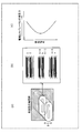
- Test results The test results are shown in Table 1 below.
- the adhesive force ratio is 0.1 or more and 0.9 or less before and after the electrolytic solution is contained in the electrode, the productivity and the liquid We were able to produce an electrode body with excellent rotation (liquid permeability). Furthermore, according to the above-mentioned one test example, when the adhesive force ratio is 0.4 or less before and after the electrolytic solution is contained in the electrode, the electrode body is excellent in both productivity and liquid circulation. Was able to be produced. According to a plurality of tests conducted by the inventor of the present application in which the temperature condition of the hot plate in the pressing process, the pressure condition applied by the hot plate, and the pressing time of the hot plate are changed, the adhesive force ratio is 0.1 or more. If it is 0.9 or less, an electrode body having good productivity and liquid circulation can be produced, and if the adhesive force ratio is 0.3 or more and 0.5 or less, the productivity and liquid circulation are good. It was confirmed that an electrode body excellent in both could be produced.
- the secondary battery 10 of the present disclosure includes an adhesive 50 arranged between at least one side surface of the separator 40 in the thickness direction and the negative electrode (first electrode) 30. Further, in the secondary battery 10 of the present disclosure, the adhesive force between the negative electrode 30 of the outermost layer and the separator 40 is set to A0 [N / m], and the negative electrode 30 and the separator located at the center in the stacking direction in the laminated group (laminated body) 11A. When the adhesive strength of 40 is A1 [N / m], A1 / A0 is 0.1 or more and less than 0.9.
- the electrolytic solution can be permeated to the inside in the stacking direction in a short time. Therefore, the secondary battery 10 can be manufactured in a short time so that the holding amount of the electrolytic solution can be easily made uniform regardless of the existing position in the stacking direction. Therefore, not only can the power generation performance of the secondary battery 10 be improved, but also the occurrence of a reaction rate difference at the existing position in the stacking direction can be suppressed, and as a result, the durability of the secondary battery 10 can be improved, and further, the secondary battery 10 can be improved. The productivity of the next battery can also be improved.
- the long side of the negative electrode 30 may be 10 cm or more, and the area of one side surface of the negative electrode 30 in the thickness direction may be 90 cm 2 or more.
- the liquid circulation property (liquid permeability) to the central portion in the stacking direction of the electrolytic solution becomes lower as the capacity of the secondary battery 10 becomes larger.
- the secondary battery 10 is a large-capacity battery in which the long side of the negative electrode 30 is 10 cm or more and the area of one side surface of the negative electrode 30 in the thickness direction is 90 cm 2 or more. Therefore, thanks to the excellent liquid circulation of the electrolytic solution, which is one of the main effects of the technology of the present disclosure, the secondary battery is compared with the secondary battery of the conventional configuration using an adhesive. The power generation performance and durability of the 10 can be improved to each stage.
- a second adhesive arranged between the other side surface of the separator 40 in the thickness direction and the positive electrode 20 may be provided. Further, when the adhesive force between the positive electrode 20 and the separator 40 of the outermost layer is A2 [N / m] and the adhesive force between the positive electrode 20 and the separator 40 located at the center in the stacking direction in the laminated body is A3 [N / m]. , A3 / A2 may be 0.1 or more and less than 0.9.
- the electrolytic solution easily permeates into the central portion of the electrode group 11A in the stacking direction also between the positive electrode 20 and the separator 40. Therefore, the power generation performance, durability, and mass productivity of the secondary battery 10 can be further improved.
- one side surface of the separator 40 to which the adhesive is applied may be contained in a porous base material having ion permeability and insulating property (for example, a polyolefin base material).
- the adhesive force acting between the separator 40 and the electrode (at least one of the positive electrode and the negative electrode) can be increased, and the displacement of the separator 40 with respect to the electrode can be greatly suppressed.
- a porous base material having ion permeability and insulating property for example, a polyolefin base material. Good.
- the adhesive force acting between the separator 40 and the positive electrode 20 can be increased, and the adhesive force acting between the separator 40 and the negative electrode 30 can also be increased.
- the adhesive is applied to at least one side surface of the separator 40 in the thickness direction so that the area density is substantially constant, and the area density of the bonded portion of the adhesive may vary in the stacking direction. ..
- FIG. 6 is a schematic view showing the relationship between the position in the stacking direction (indicated by the arrow A) and the adhesive force between the electrode and the separator in the laminated electrode body.
- FIG. 6C in the technique of the present disclosure, in a two-dimensional graph in which the position in the stacking direction is the vertical axis and the adhesive force is the horizontal axis, the distribution of the adhesive force between the electrode and the separator is in the stacking direction.
- the function f is close to line symmetry so that both end portions are large and have a minimum value in the central portion in the stacking direction.
- such a function is applied from the hot plate to the laminate in the press process in a two-dimensional graph in which the position in the stacking direction is on the vertical axis and the amount of heat applied from the hot plate to the laminate in the press process is on the horizontal axis. It behaves similarly to a function that indicates the distribution of heat (temperature distribution). That is, the distribution (temperature distribution) of the amount of heat applied from the hot plate to the laminated body in the pressing process is also a minimum value in the central portion in the laminated direction because both end portions in the lamination direction are large as shown in FIG. 6 (c). It becomes a function close to line symmetry such that has.
- the adhesive force on the inner side (center side) in the stacking direction can be easily applied to the adhesive force on the outer side in the stacking direction. Can be made smaller. That is, according to this modification, the adhesive is applied to at least one side surface of the separator in the thickness direction so that the area density is substantially constant, but the tendency similar to the function shown by f in FIG. 6 (c) is observed. Also in the heat pressing process shown, the amount of heat distribution (temperature distribution) is used to make the amount that melts in the adhesive inside the stacking direction smaller than the amount that melts in the adhesive outside the stacking direction, and the adhesion inside the stacking direction. The amount of the adhesive portion that develops the adhesive force in the agent is made smaller than the amount of the adhesive portion that develops the adhesive force in the adhesive outside in the stacking direction.
- FIG. 7 is an enlarged schematic cross-sectional view when a part of the inside of the first electrode group 11A in the stacking direction is cut by a plane substantially orthogonal to the height direction, and the adhesive is applied as in FIG.
- the illustration of the portion where the adhesive force is not exhibited in 50 is an enlarged schematic cross-sectional view which is omitted.
- the area density of the adhesive 50 to be applied is the same both on the outside and the inside in the stacking direction, but as shown in FIGS. 5 and 7, the tendency similar to the function shown by f in FIG. 6 (c) is observed.
- the amount of the adhesive portions 50a and 50b that develop adhesive force in the adhesive 50 can be made smaller on the inner side in the stacking direction than on the outer side in the stacking direction. Therefore, the adhesive force on the inner side (center side) in the stacking direction can be easily reduced with respect to the adhesive force on the outer side in the stacking direction.
- the electrode body may be manufactured by using a plurality of different separators.
- the separator may be folded in a zigzag.
- the handleability of the laminated body (electrode group, electrode body) can be improved.
- the laminated electrode body 11 is manufactured by welding at least a part of the adhesive 50 in a hot pressing step. It may be. According to this configuration, the secondary battery 10 having the laminated electrode body 11 of the present disclosure can be easily manufactured.
- FIG. 8 is a plan view of the wound type square secondary battery 110
- FIG. 9 is a front view of the square secondary battery 110.
- 10 (a) is a sectional view taken along line AA of FIG. 8
- FIG. 10 (b) is a sectional view taken along line BB of FIG. 10 (a)
- FIG. 10 (c) is a sectional view taken along line BB.
- FIG. 10 (a) is a cross-sectional view taken along the line CC of FIG. 10 (a).
- 11A is a plan view of the positive electrode included in the square secondary battery 110, and FIG.
- FIG. 11B is a plan view of the negative electrode included in the square secondary battery 110.
- FIG. 12 is a perspective view showing the winding end end side of the flat wound electrode body included in the square secondary battery 110.
- the material of each member of the wound type square secondary battery 110 the same material as the material of the corresponding member of the above-mentioned laminated type square secondary battery 10 can be used. Therefore, in the following description, the material of each member will be briefly described or the description will be omitted.
- the square secondary battery 110 includes an outer can (square outer can) 125 (see FIGS. 8 to 10) and a sealing plate. It includes 123 (see FIG. 8) and a flat wound electrode body 114 (see FIGS. 9A and 12).
- the outer can 125 is made of, for example, aluminum or an aluminum alloy, and has an opening on one side in the height direction. As shown in FIG. 9, the outer can 125 has a bottom 140, a pair of first side surfaces 141, and a pair of second side surfaces 142, and the second side surface 142 is larger than the first side surface 141. As shown in FIG.
- the sealing plate 123 is fitted into the opening of the outer can 125.
- a square battery case 145 is formed by joining the fitting portion between the sealing plate 123 and the outer can 125.
- the material of each member in the wound type secondary battery 110 the same material as the material of the corresponding member in the laminated type square secondary battery 10 can be adopted. Therefore, in the following description of the winding type secondary battery 110, the material of each member will be briefly described or the description will be omitted.
- the wound electrode body 114 has a structure in which the positive electrode 111 and the negative electrode 112 are wound in a state of being insulated from each other via the separator 113.
- the outermost surface side of the wound electrode body 114 is covered with the separator 113, and the negative electrode 112 is arranged on the outer peripheral side of the positive electrode 111.
- the positive electrode 111 is determined by applying a positive electrode mixture slurry on both sides of a strip-shaped positive electrode core 115 made of aluminum or an aluminum alloy foil having a thickness of about 10 to 20 ⁇ m, drying and compressing the slurry. Cut into strips to the dimensions.
- the positive electrode mixture slurry contains a positive electrode active material, a conductive agent, a binder and the like. At this time, a positive electrode core body exposed portion 115a in which the positive electrode mixture layer 111a is not formed on both sides along the longitudinal direction is formed at one end in the width direction.
- a positive electrode protective layer 111b is formed on the surface of at least one side of the positive electrode core body exposed portion 115a along the length direction of the positive electrode core body exposed portion 115a so as to be adjacent to, for example, the positive electrode mixture layer 111a. Is preferable.
- the positive electrode protective layer 111b contains insulating inorganic particles and a binder.
- the positive electrode protective layer 111b has lower conductivity than the positive electrode mixture layer 111a.
- the positive electrode protective layer 111b By providing the positive electrode protective layer 111b, it is possible to prevent a short circuit between the negative electrode mixture layer 112a and the positive electrode core 115 due to foreign matter or the like. Further, the positive electrode protective layer 111b can contain conductive inorganic particles. The positive electrode protective layer 111b may not be provided.
- the negative electrode 112 is formed by applying a negative electrode mixture slurry to both surfaces of a strip-shaped negative electrode core 116 made of copper or a copper alloy foil having a thickness of about 5 to 15 ⁇ m, drying and compressing the negative electrode 112. , Cut into strips to the specified dimensions.
- the negative electrode mixture slurry contains a negative electrode active material, a binder and the like.
- the negative electrode core body exposed portion 116a in which the negative electrode mixture layer 112a is not formed on both sides along the longitudinal direction is formed.
- the positive electrode core body exposed portion 115a to the negative electrode core body exposed portion 116a may be formed along the ends on both sides of the positive electrode 111 to the negative electrode 112 in the width direction, respectively.
- the positive electrode 111 and the negative electrode 112 do not overlap the positive electrode core body exposed portion 115a and the negative electrode mixture layer 112a, and the negative electrode core body exposed portion 116a and the positive electrode mixture layer 111a do not overlap.
- the positive electrode 111 and the negative electrode 112 are wound so as to be insulated from each other with the separator 113 coated with the adhesive having a substantially constant area density on at least one side surface in the thickness direction.
- the formed wound body is sandwiched between a pair of hot plates and formed into a flat shape to produce a flat wound electrode body 114.
- a plurality of winding electrode bodies 114 are provided at one end in the direction in which the winding axis extends (corresponding to the width direction when the band-shaped positive electrode 111, the band-shaped negative electrode 112, and the band-shaped separator 113 are developed in a rectangular shape).
- a laminated positive electrode core body exposed portion 115a is provided, and a plurality of laminated negative electrode core body exposed portions 116a are provided at the other end portion.
- a porous polyolefin film can be preferably used as the separator 113. It is preferable that the width of the separator 113 can cover the positive electrode mixture layer 111a and the positive electrode protective layer 111b and is larger than the width of the negative electrode mixture layer 112a.
- the exposed positive electrode core body 115a in which a plurality of sheets are laminated is electrically connected to the positive electrode terminal 118 via the positive electrode current collector 117 (see FIG. 10A), and the plurality of sheets are laminated.
- the negative electrode core body exposed portion 116a is electrically connected to the negative electrode terminal 120 via the negative electrode current collector 119 (see FIG. 10A).
- an operation is performed between the positive electrode current collector 117 and the positive electrode terminal 118 when the gas pressure inside the battery case 145 exceeds a predetermined value. It is preferable that the current cutoff mechanism 127 is provided.
- the positive electrode terminal 118 and the negative electrode terminal 120 are fixed to the sealing plate 123 via the insulating members 121 and 122, respectively.
- the sealing plate 123 has a gas discharge valve 128 that is opened when the gas pressure in the battery case 145 becomes higher than the operating pressure of the current cutoff mechanism 127.
- the positive electrode current collector 117, the positive electrode terminal 118, and the sealing plate 123 are each made of aluminum or an aluminum alloy, and the negative electrode current collector 119 and the negative electrode terminal 120 are each made of copper or a copper alloy. As shown in FIG.
- the flat wound electrode body 114 has an exterior in which one surface is open with an insulating insulating sheet (resin sheet) 124 interposed around the periphery except for the sealing plate 123 side. It is inserted into the can 125.
- an insulating insulating sheet (resin sheet) 124 interposed around the periphery except for the sealing plate 123 side. It is inserted into the can 125.
- the plurality of positive electrode core body exposed portions 115a wound and laminated are converged to the central portion in the thickness direction and further 2 It is divided, the positive electrode core body exposed portion 115a is converged, and the positive electrode intermediate member 130 is arranged between them.
- the positive electrode intermediate member 130 is made of a resin material, and the positive electrode intermediate member 130 holds one or more, for example, two conductive positive electrode conductive members 129.
- the positive electrode conductive member 129 for example, a columnar one is used, and truncated cone-shaped protrusions acting as projections are formed on both ends facing the laminated positive electrode core body exposed portions 115a.
- the plurality of negative electrode core body exposed portions 116a that are wound and laminated are converged to the center side in the thickness direction and further divided into two, and the negative electrode core body exposed portion 116a is converged during that time.
- An intermediate member 132 is arranged.
- the negative electrode intermediate member 132 is made of a resin material, and the negative electrode intermediate member 132 holds one or more, for example, two negative electrode conductive members 131.
- As the negative electrode conductive member 131 for example, a cylindrical one is used, and truncated cone-shaped protrusions acting as projections are formed at both ends facing the laminated negative electrode core body exposed portions 116a.
- the positive electrode conductive member 129 and the converged positive electrode core body exposed portions 115a arranged on both sides in the extending direction thereof are joined and electrically connected, and the converged positive electrode core body exposed portion 115a and the convergent positive electrode core body exposed portion 115a thereof.
- the positive electrode current collector 117 arranged on the outer side of the battery case 145 in the depth direction is also joined and electrically connected.
- the negative electrode conductive member 131 and the negative electrode core exposed portion 116a arranged on both sides thereof and converged are joined and electrically connected, and the converged negative electrode core exposed portion 116a and its
- the negative electrode current collector 119 arranged outside the battery case 145 in the depth direction is also joined and electrically connected.
- the end of the positive electrode current collector 117 opposite to the exposed positive electrode core 115a side is electrically connected to the positive electrode terminal 118, and is opposite to the exposed negative electrode core 116a side of the negative electrode current collector 119.
- the end is electrically connected to the negative electrode terminal 120.
- the positive electrode core body exposed portion 115a is electrically connected to the positive electrode terminal 118
- the negative electrode core body exposed portion 116a is electrically connected to the negative electrode terminal 120.
- the wound electrode body 114, the intermediate members 130 and 132 for the positive electrode and the negative electrode, and the conductive members 129 and 131 for the positive electrode and the negative electrode are connected to form an integrated structure.
- the positive electrode conductive member 129 is preferably made of aluminum or an aluminum alloy, which is the same material as the positive electrode core 115
- the negative electrode conductive member 131 is preferably made of copper or a copper alloy, which is the same material as the negative electrode core 116. preferable.
- the shapes of the positive electrode conductive member 129 and the negative electrode conductive member 131 may be the same or different.
- connection between the positive electrode core body exposed portion 115a and the positive electrode current collector 117 and the connection between the negative electrode core body exposed portion 116a and the negative electrode current collector 119 resistance welding, laser welding, ultrasonic welding or the like may be used. Further, it is not necessary to use the positive electrode intermediate member 130 and the negative electrode intermediate member 132.
- the sealing plate 123 is provided with an electrolytic solution injection hole 126.
- the wound electrode body 114 to which the positive electrode current collector 117, the negative electrode current collector 119, the sealing plate 123, and the like are attached is arranged in the outer can 125.
- the fitting portion between the sealing plate 123 and the outer can 125 is laser-welded, and then the non-aqueous electrolytic solution is injected from the electrolytic solution injection hole 126.
- the secondary battery 110 is manufactured by sealing the electrolytic solution injection hole 126. Sealing of the electrolytic solution injection hole 126 is performed by, for example, blind rivet or welding.
- winding electrode body 114 is arranged so that the winding shaft thereof is parallel to the bottom 140 of the outer can 125 has been described, but the winding electrode body has a winding shaft of the outer can 125. It may be arranged so as to be perpendicular to the bottom 140.
- the electrolyte (electrolyte solution) is central to any winding type secondary battery 110, not limited to the above-mentioned winding type secondary battery 110. There is a problem that it is difficult to penetrate into the cavity side.
- the press directions B in the above correspond to each other.
- the temperature on the inner peripheral side becomes lower than the temperature on the outer peripheral side.
- the outside of the laminated electrode body 11 in the stacking direction corresponds to the outer peripheral side of the wound electrode body 114, and the inside (center side) of the laminated electrode body 11 in the stacking direction is the wound electrode body 114.
- the secondary battery 110 includes a strip-shaped positive electrode 111 having a positive electrode active material arranged on the positive electrode core 115 and the positive electrode core 115, and negative electrode activity arranged on the negative electrode core 116 and the negative electrode core 116.
- a band-shaped negative electrode 112 having a substance includes a wound body in which five or more turns are wound via a band-shaped separator 113.
- the secondary battery 110 includes an adhesive in which the winding body is arranged between at least one side surface of the separator 113 in the thickness direction and at least one electrode (first electrode).
- the adhesive force between at least one electrode (first electrode) located on the outermost periphery and the separator is set to A0 [N / m], and the adhesive force between the at least one electrode (first electrode) located on the innermost circumference and the separator is adhered.
- A1 [N / m] A1 / A0 is 0.1 or more and less than 0.9.
- the secondary battery 110 has good power generation performance, durability, and mass productivity.
- the winding body may have a flat shape
- the length of the winding body in the height direction of the battery 110 may be 10 cm or more
- the length of the winding body in the lateral direction of the battery 110 may be 9 cm or more. ..
- the liquid circulation property (liquid permeability) of the electrolytic solution to the inner peripheral side in the wound body becomes lower as the capacity of the secondary battery 110 becomes larger.
- the secondary battery 110 is a large-capacity battery in which the thickness of the wound body is 10 cm or more and the peripheral length of the outermost circumference is 9 cm or more. Therefore, thanks to the excellent liquid circulation property of the electrolytic solution, which is one of the main effects of the technique of the present disclosure, the power generation performance and durability of the secondary battery 110 can be further improved. ..
- a second adhesive is provided between the other side surface of the separator 113 in the thickness direction and the other electrode, and the adhesive force between the other electrode located on the outermost periphery and the separator is A2 [N / m].
- A3 / A2 may be 0.1 or more and less than 0.9.
- the liquid circulation property (liquid permeability) between the other electrode and the separator 113 on the inner peripheral side of the wound body can also be increased. Therefore, the power generation performance, durability, and mass productivity of the secondary battery 110 can be further improved.
- At least one side surface on which the adhesive is arranged in the separator 113 may be contained in a porous base material having ion permeability and insulating property (for example, a polyolefin base material).
- the adhesive force acting between the separator 113 and at least one electrode can be increased, and the displacement of the separator 113 with respect to the electrode can be greatly suppressed.
- a porous base material having ion permeability and insulating property for example, a polyolefin base material. Good.
- the adhesive force acting between the separator 113 and the positive electrode 111 can be increased, and the adhesive force acting between the separator 113 and the negative electrode 112 can also be increased.
- the adhesive may be applied to at least one side surface of the separator 113 in the thickness direction so that the area density is substantially constant. Then, the area density of the bonded portion of the adhesive may vary from layer to layer of the wound body, and more specifically, the area density of the bonded portion of the inner peripheral side layer rather than the outer peripheral side layer may be changed. May be varied so that
- the productivity of the secondary battery can be significantly improved.
- the wound electrode body 114 may be manufactured by welding at least a part of the adhesive in a hot pressing step. Good. According to this configuration, the secondary battery 110 having the wound electrode body 114 of the present disclosure can be easily manufactured.
Landscapes
- Chemical & Material Sciences (AREA)
- Chemical Kinetics & Catalysis (AREA)
- Electrochemistry (AREA)
- General Chemical & Material Sciences (AREA)
- Engineering & Computer Science (AREA)
- Manufacturing & Machinery (AREA)
- Secondary Cells (AREA)
Abstract
L'invention concerne une batterie secondaire qui comprend un adhésif qui est disposé sur au moins une surface latérale dans la direction de l'épaisseur de séparateurs entre les séparateurs et les premières électrodes (électrodes négatives). Lorsque la force adhésive entre un séparateur et la première électrode la plus à l'extérieur (électrode négative) est A0 [N/m] et la force adhésive entre un séparateur et la première électrode (électrode négative) qui est au centre du stratifié dans la direction de stratification est A1 [N/M], A1/A0 est d'au moins 0,1 mais inférieure à 0,9.
Priority Applications (4)
| Application Number | Priority Date | Filing Date | Title |
|---|---|---|---|
| EP20904827.1A EP4084184A4 (fr) | 2019-12-26 | 2020-12-15 | Batterie secondaire et son procédé de production |
| JP2021567286A JPWO2021131877A1 (fr) | 2019-12-26 | 2020-12-15 | |
| CN202080089149.5A CN114846671A (zh) | 2019-12-26 | 2020-12-15 | 二次电池及其制造方法 |
| US17/786,820 US20230031407A1 (en) | 2019-12-26 | 2020-12-15 | Secondary battery and production method for same |
Applications Claiming Priority (2)
| Application Number | Priority Date | Filing Date | Title |
|---|---|---|---|
| JP2019236097 | 2019-12-26 | ||
| JP2019-236097 | 2019-12-26 |
Publications (1)
| Publication Number | Publication Date |
|---|---|
| WO2021131877A1 true WO2021131877A1 (fr) | 2021-07-01 |
Family
ID=76574546
Family Applications (1)
| Application Number | Title | Priority Date | Filing Date |
|---|---|---|---|
| PCT/JP2020/046639 WO2021131877A1 (fr) | 2019-12-26 | 2020-12-15 | Batterie secondaire et son procédé de production |
Country Status (5)
| Country | Link |
|---|---|
| US (1) | US20230031407A1 (fr) |
| EP (1) | EP4084184A4 (fr) |
| JP (1) | JPWO2021131877A1 (fr) |
| CN (1) | CN114846671A (fr) |
| WO (1) | WO2021131877A1 (fr) |
Cited By (1)
| Publication number | Priority date | Publication date | Assignee | Title |
|---|---|---|---|---|
| JP7459157B2 (ja) | 2022-03-14 | 2024-04-01 | プライムプラネットエナジー&ソリューションズ株式会社 | 電池 |
Families Citing this family (1)
| Publication number | Priority date | Publication date | Assignee | Title |
|---|---|---|---|---|
| JP2024119116A (ja) * | 2023-02-22 | 2024-09-03 | プライムプラネットエナジー&ソリューションズ株式会社 | 蓄電デバイスの製造方法ならびに蓄電デバイス用セパレータ |
Citations (6)
| Publication number | Priority date | Publication date | Assignee | Title |
|---|---|---|---|---|
| WO1999026306A1 (fr) * | 1997-11-19 | 1999-05-27 | Mitsubishi Denki Kabushiki Kaisha | Batterie secondaire aux ions de lithium et fabrication de cette derniere |
| JP2011054502A (ja) * | 2009-09-04 | 2011-03-17 | Hitachi Maxell Ltd | リチウム二次電池およびその製造方法 |
| JP2014026943A (ja) * | 2012-07-30 | 2014-02-06 | Nissan Motor Co Ltd | 積層構造電池 |
| JP2014120456A (ja) * | 2012-12-19 | 2014-06-30 | Nissan Motor Co Ltd | 二次電池 |
| JP2018067396A (ja) * | 2016-10-17 | 2018-04-26 | 株式会社カネカ | リチウムイオン二次電池 |
| WO2019156172A1 (fr) * | 2018-02-08 | 2019-08-15 | 積水化学工業株式会社 | Batterie secondaire au lithium-ion, structure d'électrode négative de batterie secondaire au lithium-ion, et procédé de production d'une batterie secondaire au lithium-ion |
Family Cites Families (4)
| Publication number | Priority date | Publication date | Assignee | Title |
|---|---|---|---|---|
| JP2013243070A (ja) * | 2012-05-22 | 2013-12-05 | Sanyo Electric Co Ltd | 巻回電極体を備えた電池 |
| PL3352248T3 (pl) * | 2016-04-01 | 2020-06-29 | Lg Chem, Ltd. | Separator zawierający warstwę adhezyjną dla urządzenia elektrochemicznego i zespół elektrod go zawierający |
| WO2018186205A1 (fr) * | 2017-04-07 | 2018-10-11 | 株式会社村田製作所 | Accumulateur et son procédé de fabrication |
| CN110546804B (zh) * | 2017-05-12 | 2024-02-27 | 松下控股株式会社 | 非水电解质二次电池 |
-
2020
- 2020-12-15 US US17/786,820 patent/US20230031407A1/en active Pending
- 2020-12-15 EP EP20904827.1A patent/EP4084184A4/fr active Pending
- 2020-12-15 WO PCT/JP2020/046639 patent/WO2021131877A1/fr unknown
- 2020-12-15 JP JP2021567286A patent/JPWO2021131877A1/ja active Pending
- 2020-12-15 CN CN202080089149.5A patent/CN114846671A/zh active Pending
Patent Citations (6)
| Publication number | Priority date | Publication date | Assignee | Title |
|---|---|---|---|---|
| WO1999026306A1 (fr) * | 1997-11-19 | 1999-05-27 | Mitsubishi Denki Kabushiki Kaisha | Batterie secondaire aux ions de lithium et fabrication de cette derniere |
| JP2011054502A (ja) * | 2009-09-04 | 2011-03-17 | Hitachi Maxell Ltd | リチウム二次電池およびその製造方法 |
| JP2014026943A (ja) * | 2012-07-30 | 2014-02-06 | Nissan Motor Co Ltd | 積層構造電池 |
| JP2014120456A (ja) * | 2012-12-19 | 2014-06-30 | Nissan Motor Co Ltd | 二次電池 |
| JP2018067396A (ja) * | 2016-10-17 | 2018-04-26 | 株式会社カネカ | リチウムイオン二次電池 |
| WO2019156172A1 (fr) * | 2018-02-08 | 2019-08-15 | 積水化学工業株式会社 | Batterie secondaire au lithium-ion, structure d'électrode négative de batterie secondaire au lithium-ion, et procédé de production d'une batterie secondaire au lithium-ion |
Non-Patent Citations (1)
| Title |
|---|
| See also references of EP4084184A4 * |
Cited By (1)
| Publication number | Priority date | Publication date | Assignee | Title |
|---|---|---|---|---|
| JP7459157B2 (ja) | 2022-03-14 | 2024-04-01 | プライムプラネットエナジー&ソリューションズ株式会社 | 電池 |
Also Published As
| Publication number | Publication date |
|---|---|
| JPWO2021131877A1 (fr) | 2021-07-01 |
| EP4084184A1 (fr) | 2022-11-02 |
| EP4084184A4 (fr) | 2023-12-27 |
| CN114846671A (zh) | 2022-08-02 |
| US20230031407A1 (en) | 2023-02-02 |
Similar Documents
| Publication | Publication Date | Title |
|---|---|---|
| JP5697276B2 (ja) | 新規な構造を有する電極組立体およびその製造方法 | |
| CN110546804B (zh) | 非水电解质二次电池 | |
| WO2017163932A1 (fr) | Batterie rechargeable à électrolyte non aqueux | |
| WO2011002064A1 (fr) | Batterie stratifiée | |
| WO2017077698A1 (fr) | Plaque d'électrode destinée à un dispositif de stockage d'énergie, et dispositif de stockage d'énergie | |
| WO2018168628A1 (fr) | Batterie rechargeable à électrolyte non aqueux | |
| WO2021131877A1 (fr) | Batterie secondaire et son procédé de production | |
| WO2021131878A1 (fr) | Batterie secondaire | |
| JP2011198742A (ja) | ラミネート形電池 | |
| JP5999433B2 (ja) | 非水電解液二次電池及びその製造方法 | |
| WO2021131879A1 (fr) | Batterie secondaire | |
| CN109923700B (zh) | 非水电解质二次电池用电极以及非水电解质二次电池 | |
| JP2011129446A (ja) | ラミネート形電池 | |
| WO2019069890A1 (fr) | Batterie secondaire à électrolyte non aqueux | |
| US11502375B2 (en) | Separator for nonaqueous electrolyte secondary batteries and nonaqueous electrolyte secondary battery | |
| WO2021131880A1 (fr) | Batterie secondaire | |
| JP2011216205A (ja) | ラミネート形電池およびその製造方法 | |
| JP2011216209A (ja) | ラミネート形電池およびその製造方法 | |
| JP7320166B2 (ja) | 二次電池 | |
| KR20180032763A (ko) | 전극과 분리막이 부분 결착된 전극조립체 | |
| JP2011108538A (ja) | ラミネート形電池 | |
| JP6681017B2 (ja) | 電極体を有する二次電池 | |
| JP7430665B2 (ja) | 二次電池の集電体およびその製造方法、ならびに二次電池 | |
| WO2021166720A1 (fr) | Batterie secondaire à électrolyte non aqueux et son procédé de fabrication | |
| WO2022196445A1 (fr) | Batterie secondaire à électrolyte non aqueux |
Legal Events
| Date | Code | Title | Description |
|---|---|---|---|
| 121 | Ep: the epo has been informed by wipo that ep was designated in this application |
Ref document number: 20904827 Country of ref document: EP Kind code of ref document: A1 |
|
| ENP | Entry into the national phase |
Ref document number: 2021567286 Country of ref document: JP Kind code of ref document: A |
|
| NENP | Non-entry into the national phase |
Ref country code: DE |
|
| ENP | Entry into the national phase |
Ref document number: 2020904827 Country of ref document: EP Effective date: 20220726 |