WO2021131880A1 - Batterie secondaire - Google Patents
Batterie secondaire Download PDFInfo
- Publication number
- WO2021131880A1 WO2021131880A1 PCT/JP2020/046642 JP2020046642W WO2021131880A1 WO 2021131880 A1 WO2021131880 A1 WO 2021131880A1 JP 2020046642 W JP2020046642 W JP 2020046642W WO 2021131880 A1 WO2021131880 A1 WO 2021131880A1
- Authority
- WO
- WIPO (PCT)
- Prior art keywords
- separator
- electrode
- negative electrode
- layer
- positive electrode
- Prior art date
Links
- 238000003825 pressing Methods 0.000 claims abstract description 8
- 239000010410 layer Substances 0.000 claims description 97
- 229920005989 resin Polymers 0.000 claims description 32
- 239000011347 resin Substances 0.000 claims description 32
- 239000012790 adhesive layer Substances 0.000 claims description 14
- 239000010954 inorganic particle Substances 0.000 claims description 8
- 238000010030 laminating Methods 0.000 abstract description 2
- 238000003475 lamination Methods 0.000 abstract 1
- 239000000203 mixture Substances 0.000 description 39
- 239000000463 material Substances 0.000 description 25
- 238000007789 sealing Methods 0.000 description 13
- -1 Lithium transition metal Chemical class 0.000 description 12
- 239000011230 binding agent Substances 0.000 description 11
- OKTJSMMVPCPJKN-UHFFFAOYSA-N Carbon Chemical group [C] OKTJSMMVPCPJKN-UHFFFAOYSA-N 0.000 description 9
- 239000002002 slurry Substances 0.000 description 8
- 238000007667 floating Methods 0.000 description 7
- 229910052751 metal Inorganic materials 0.000 description 7
- 239000011255 nonaqueous electrolyte Substances 0.000 description 7
- 150000003839 salts Chemical class 0.000 description 7
- 238000004804 winding Methods 0.000 description 7
- 239000002033 PVDF binder Substances 0.000 description 6
- 239000011248 coating agent Substances 0.000 description 6
- 238000000576 coating method Methods 0.000 description 6
- 239000003792 electrolyte Substances 0.000 description 6
- 229910002804 graphite Inorganic materials 0.000 description 6
- 239000010439 graphite Substances 0.000 description 6
- 238000002347 injection Methods 0.000 description 6
- 239000007924 injection Substances 0.000 description 6
- 239000007788 liquid Substances 0.000 description 6
- 239000002184 metal Substances 0.000 description 6
- 239000007773 negative electrode material Substances 0.000 description 6
- 229920002981 polyvinylidene fluoride Polymers 0.000 description 6
- 239000000853 adhesive Substances 0.000 description 5
- 230000001070 adhesive effect Effects 0.000 description 5
- 229910052782 aluminium Inorganic materials 0.000 description 5
- 230000000052 comparative effect Effects 0.000 description 5
- 239000007774 positive electrode material Substances 0.000 description 5
- 229920000178 Acrylic resin Polymers 0.000 description 4
- 239000004925 Acrylic resin Substances 0.000 description 4
- 229920002134 Carboxymethyl cellulose Polymers 0.000 description 4
- SECXISVLQFMRJM-UHFFFAOYSA-N N-Methylpyrrolidone Chemical compound CN1CCCC1=O SECXISVLQFMRJM-UHFFFAOYSA-N 0.000 description 4
- 239000003125 aqueous solvent Substances 0.000 description 4
- 229910052744 lithium Inorganic materials 0.000 description 4
- 239000002905 metal composite material Substances 0.000 description 4
- 238000000034 method Methods 0.000 description 4
- 229910052759 nickel Inorganic materials 0.000 description 4
- PXHVJJICTQNCMI-UHFFFAOYSA-N nickel Substances [Ni] PXHVJJICTQNCMI-UHFFFAOYSA-N 0.000 description 4
- 229920001721 polyimide Polymers 0.000 description 4
- 238000002360 preparation method Methods 0.000 description 4
- 229920003048 styrene butadiene rubber Polymers 0.000 description 4
- 229910052723 transition metal Inorganic materials 0.000 description 4
- 239000004642 Polyimide Substances 0.000 description 3
- 239000002390 adhesive tape Substances 0.000 description 3
- XAGFODPZIPBFFR-UHFFFAOYSA-N aluminium Chemical compound [Al] XAGFODPZIPBFFR-UHFFFAOYSA-N 0.000 description 3
- PNEYBMLMFCGWSK-UHFFFAOYSA-N aluminium oxide Inorganic materials [O-2].[O-2].[O-2].[Al+3].[Al+3] PNEYBMLMFCGWSK-UHFFFAOYSA-N 0.000 description 3
- 239000002388 carbon-based active material Substances 0.000 description 3
- 239000004020 conductor Substances 0.000 description 3
- 239000011888 foil Substances 0.000 description 3
- 239000007789 gas Substances 0.000 description 3
- 230000010220 ion permeability Effects 0.000 description 3
- 229910052748 manganese Inorganic materials 0.000 description 3
- 239000011572 manganese Substances 0.000 description 3
- 239000002245 particle Substances 0.000 description 3
- 229920002239 polyacrylonitrile Polymers 0.000 description 3
- RYGMFSIKBFXOCR-UHFFFAOYSA-N Copper Chemical compound [Cu] RYGMFSIKBFXOCR-UHFFFAOYSA-N 0.000 description 2
- KMTRUDSVKNLOMY-UHFFFAOYSA-N Ethylene carbonate Chemical compound O=C1OCCO1 KMTRUDSVKNLOMY-UHFFFAOYSA-N 0.000 description 2
- 229910013870 LiPF 6 Inorganic materials 0.000 description 2
- HBBGRARXTFLTSG-UHFFFAOYSA-N Lithium ion Chemical compound [Li+] HBBGRARXTFLTSG-UHFFFAOYSA-N 0.000 description 2
- 229920003171 Poly (ethylene oxide) Polymers 0.000 description 2
- 239000004698 Polyethylene Substances 0.000 description 2
- 239000004743 Polypropylene Substances 0.000 description 2
- 239000004372 Polyvinyl alcohol Substances 0.000 description 2
- VYPSYNLAJGMNEJ-UHFFFAOYSA-N Silicium dioxide Chemical compound O=[Si]=O VYPSYNLAJGMNEJ-UHFFFAOYSA-N 0.000 description 2
- 229920002125 Sokalan® Polymers 0.000 description 2
- 239000002174 Styrene-butadiene Substances 0.000 description 2
- GWEVSGVZZGPLCZ-UHFFFAOYSA-N Titan oxide Chemical compound O=[Ti]=O GWEVSGVZZGPLCZ-UHFFFAOYSA-N 0.000 description 2
- MCMNRKCIXSYSNV-UHFFFAOYSA-N Zirconium dioxide Chemical compound O=[Zr]=O MCMNRKCIXSYSNV-UHFFFAOYSA-N 0.000 description 2
- 239000006230 acetylene black Substances 0.000 description 2
- 229910021383 artificial graphite Inorganic materials 0.000 description 2
- 238000005452 bending Methods 0.000 description 2
- 229910001593 boehmite Inorganic materials 0.000 description 2
- 239000001768 carboxy methyl cellulose Substances 0.000 description 2
- 235000010948 carboxy methyl cellulose Nutrition 0.000 description 2
- 239000008112 carboxymethyl-cellulose Substances 0.000 description 2
- 239000002131 composite material Substances 0.000 description 2
- 229920001577 copolymer Polymers 0.000 description 2
- 229910052802 copper Inorganic materials 0.000 description 2
- 239000010949 copper Substances 0.000 description 2
- 239000002612 dispersion medium Substances 0.000 description 2
- 238000001035 drying Methods 0.000 description 2
- 239000008151 electrolyte solution Substances 0.000 description 2
- 238000011156 evaluation Methods 0.000 description 2
- FAHBNUUHRFUEAI-UHFFFAOYSA-M hydroxidooxidoaluminium Chemical compound O[Al]=O FAHBNUUHRFUEAI-UHFFFAOYSA-M 0.000 description 2
- 229910001416 lithium ion Inorganic materials 0.000 description 2
- 238000002844 melting Methods 0.000 description 2
- 230000008018 melting Effects 0.000 description 2
- 239000012046 mixed solvent Substances 0.000 description 2
- 229920000573 polyethylene Polymers 0.000 description 2
- 229920005672 polyolefin resin Polymers 0.000 description 2
- 229920001155 polypropylene Polymers 0.000 description 2
- 229920001343 polytetrafluoroethylene Polymers 0.000 description 2
- 239000004810 polytetrafluoroethylene Substances 0.000 description 2
- 229920002451 polyvinyl alcohol Polymers 0.000 description 2
- 230000008569 process Effects 0.000 description 2
- 239000002409 silicon-based active material Substances 0.000 description 2
- 239000007787 solid Substances 0.000 description 2
- 239000000126 substance Substances 0.000 description 2
- 239000002344 surface layer Substances 0.000 description 2
- XLYOFNOQVPJJNP-UHFFFAOYSA-N water Substances O XLYOFNOQVPJJNP-UHFFFAOYSA-N 0.000 description 2
- 229910000838 Al alloy Inorganic materials 0.000 description 1
- PXGOKWXKJXAPGV-UHFFFAOYSA-N Fluorine Chemical compound FF PXGOKWXKJXAPGV-UHFFFAOYSA-N 0.000 description 1
- UFHFLCQGNIYNRP-UHFFFAOYSA-N Hydrogen Chemical compound [H][H] UFHFLCQGNIYNRP-UHFFFAOYSA-N 0.000 description 1
- 239000004952 Polyamide Substances 0.000 description 1
- 239000004962 Polyamide-imide Substances 0.000 description 1
- 239000004697 Polyetherimide Substances 0.000 description 1
- 239000004734 Polyphenylene sulfide Substances 0.000 description 1
- SOXUFMZTHZXOGC-UHFFFAOYSA-N [Li].[Mn].[Co].[Ni] Chemical compound [Li].[Mn].[Co].[Ni] SOXUFMZTHZXOGC-UHFFFAOYSA-N 0.000 description 1
- 230000005856 abnormality Effects 0.000 description 1
- 150000001408 amides Chemical class 0.000 description 1
- 239000004760 aramid Substances 0.000 description 1
- 229920003235 aromatic polyamide Polymers 0.000 description 1
- 229910052796 boron Inorganic materials 0.000 description 1
- QHIWVLPBUQWDMQ-UHFFFAOYSA-N butyl prop-2-enoate;methyl 2-methylprop-2-enoate;prop-2-enoic acid Chemical compound OC(=O)C=C.COC(=O)C(C)=C.CCCCOC(=O)C=C QHIWVLPBUQWDMQ-UHFFFAOYSA-N 0.000 description 1
- 229910052799 carbon Inorganic materials 0.000 description 1
- 239000003575 carbonaceous material Substances 0.000 description 1
- 229920002678 cellulose Polymers 0.000 description 1
- 239000001913 cellulose Substances 0.000 description 1
- 230000008859 change Effects 0.000 description 1
- 229910052804 chromium Inorganic materials 0.000 description 1
- 150000001875 compounds Chemical class 0.000 description 1
- 239000011889 copper foil Substances 0.000 description 1
- 230000006866 deterioration Effects 0.000 description 1
- IEJIGPNLZYLLBP-UHFFFAOYSA-N dimethyl carbonate Chemical compound COC(=O)OC IEJIGPNLZYLLBP-UHFFFAOYSA-N 0.000 description 1
- 238000007599 discharging Methods 0.000 description 1
- 238000006073 displacement reaction Methods 0.000 description 1
- 230000000694 effects Effects 0.000 description 1
- 239000000839 emulsion Substances 0.000 description 1
- 150000002148 esters Chemical class 0.000 description 1
- 150000002170 ethers Chemical class 0.000 description 1
- JBTWLSYIZRCDFO-UHFFFAOYSA-N ethyl methyl carbonate Chemical compound CCOC(=O)OC JBTWLSYIZRCDFO-UHFFFAOYSA-N 0.000 description 1
- 229910052731 fluorine Inorganic materials 0.000 description 1
- 239000011737 fluorine Substances 0.000 description 1
- 125000005843 halogen group Chemical group 0.000 description 1
- 150000002367 halogens Chemical group 0.000 description 1
- 230000020169 heat generation Effects 0.000 description 1
- 238000010438 heat treatment Methods 0.000 description 1
- 238000007731 hot pressing Methods 0.000 description 1
- 229910052739 hydrogen Inorganic materials 0.000 description 1
- 239000001257 hydrogen Substances 0.000 description 1
- 229910052738 indium Inorganic materials 0.000 description 1
- 229910052742 iron Inorganic materials 0.000 description 1
- 239000003273 ketjen black Substances 0.000 description 1
- 229910003002 lithium salt Inorganic materials 0.000 description 1
- 159000000002 lithium salts Chemical class 0.000 description 1
- 238000005461 lubrication Methods 0.000 description 1
- 229910052749 magnesium Inorganic materials 0.000 description 1
- 239000007769 metal material Substances 0.000 description 1
- 239000011325 microbead Substances 0.000 description 1
- 230000004048 modification Effects 0.000 description 1
- 238000012986 modification Methods 0.000 description 1
- 229910021382 natural graphite Inorganic materials 0.000 description 1
- 229910052758 niobium Inorganic materials 0.000 description 1
- 150000002825 nitriles Chemical class 0.000 description 1
- 230000001590 oxidative effect Effects 0.000 description 1
- 230000002093 peripheral effect Effects 0.000 description 1
- 239000004584 polyacrylic acid Substances 0.000 description 1
- 229920002647 polyamide Polymers 0.000 description 1
- 229920002312 polyamide-imide Polymers 0.000 description 1
- 229920000728 polyester Polymers 0.000 description 1
- 229920001601 polyetherimide Polymers 0.000 description 1
- 229920000139 polyethylene terephthalate Polymers 0.000 description 1
- 239000005020 polyethylene terephthalate Substances 0.000 description 1
- 239000009719 polyimide resin Substances 0.000 description 1
- 229920000098 polyolefin Polymers 0.000 description 1
- 229920000069 polyphenylene sulfide Polymers 0.000 description 1
- 239000011148 porous material Substances 0.000 description 1
- 239000000377 silicon dioxide Substances 0.000 description 1
- 239000002904 solvent Substances 0.000 description 1
- 238000003860 storage Methods 0.000 description 1
- 229910052715 tantalum Inorganic materials 0.000 description 1
- 229910052718 tin Inorganic materials 0.000 description 1
- 229910052719 titanium Inorganic materials 0.000 description 1
- 229910052721 tungsten Inorganic materials 0.000 description 1
- 230000007306 turnover Effects 0.000 description 1
- 229910052720 vanadium Inorganic materials 0.000 description 1
- 229910052725 zinc Inorganic materials 0.000 description 1
- 229910052726 zirconium Inorganic materials 0.000 description 1
- 239000004711 α-olefin Substances 0.000 description 1
Images


Classifications
-
- H—ELECTRICITY
- H01—ELECTRIC ELEMENTS
- H01M—PROCESSES OR MEANS, e.g. BATTERIES, FOR THE DIRECT CONVERSION OF CHEMICAL ENERGY INTO ELECTRICAL ENERGY
- H01M10/00—Secondary cells; Manufacture thereof
- H01M10/05—Accumulators with non-aqueous electrolyte
- H01M10/058—Construction or manufacture
- H01M10/0583—Construction or manufacture of accumulators with folded construction elements except wound ones, i.e. folded positive or negative electrodes or separators, e.g. with "Z"-shaped electrodes or separators
-
- H—ELECTRICITY
- H01—ELECTRIC ELEMENTS
- H01M—PROCESSES OR MEANS, e.g. BATTERIES, FOR THE DIRECT CONVERSION OF CHEMICAL ENERGY INTO ELECTRICAL ENERGY
- H01M50/00—Constructional details or processes of manufacture of the non-active parts of electrochemical cells other than fuel cells, e.g. hybrid cells
- H01M50/10—Primary casings; Jackets or wrappings
- H01M50/102—Primary casings; Jackets or wrappings characterised by their shape or physical structure
- H01M50/103—Primary casings; Jackets or wrappings characterised by their shape or physical structure prismatic or rectangular
-
- H—ELECTRICITY
- H01—ELECTRIC ELEMENTS
- H01M—PROCESSES OR MEANS, e.g. BATTERIES, FOR THE DIRECT CONVERSION OF CHEMICAL ENERGY INTO ELECTRICAL ENERGY
- H01M10/00—Secondary cells; Manufacture thereof
- H01M10/05—Accumulators with non-aqueous electrolyte
- H01M10/052—Li-accumulators
-
- H—ELECTRICITY
- H01—ELECTRIC ELEMENTS
- H01M—PROCESSES OR MEANS, e.g. BATTERIES, FOR THE DIRECT CONVERSION OF CHEMICAL ENERGY INTO ELECTRICAL ENERGY
- H01M50/00—Constructional details or processes of manufacture of the non-active parts of electrochemical cells other than fuel cells, e.g. hybrid cells
- H01M50/10—Primary casings; Jackets or wrappings
- H01M50/116—Primary casings; Jackets or wrappings characterised by the material
- H01M50/122—Composite material consisting of a mixture of organic and inorganic materials
-
- H—ELECTRICITY
- H01—ELECTRIC ELEMENTS
- H01M—PROCESSES OR MEANS, e.g. BATTERIES, FOR THE DIRECT CONVERSION OF CHEMICAL ENERGY INTO ELECTRICAL ENERGY
- H01M50/00—Constructional details or processes of manufacture of the non-active parts of electrochemical cells other than fuel cells, e.g. hybrid cells
- H01M50/40—Separators; Membranes; Diaphragms; Spacing elements inside cells
- H01M50/409—Separators, membranes or diaphragms characterised by the material
- H01M50/449—Separators, membranes or diaphragms characterised by the material having a layered structure
- H01M50/451—Separators, membranes or diaphragms characterised by the material having a layered structure comprising layers of only organic material and layers containing inorganic material
-
- H—ELECTRICITY
- H01—ELECTRIC ELEMENTS
- H01M—PROCESSES OR MEANS, e.g. BATTERIES, FOR THE DIRECT CONVERSION OF CHEMICAL ENERGY INTO ELECTRICAL ENERGY
- H01M50/00—Constructional details or processes of manufacture of the non-active parts of electrochemical cells other than fuel cells, e.g. hybrid cells
- H01M50/40—Separators; Membranes; Diaphragms; Spacing elements inside cells
- H01M50/46—Separators, membranes or diaphragms characterised by their combination with electrodes
- H01M50/461—Separators, membranes or diaphragms characterised by their combination with electrodes with adhesive layers between electrodes and separators
-
- Y—GENERAL TAGGING OF NEW TECHNOLOGICAL DEVELOPMENTS; GENERAL TAGGING OF CROSS-SECTIONAL TECHNOLOGIES SPANNING OVER SEVERAL SECTIONS OF THE IPC; TECHNICAL SUBJECTS COVERED BY FORMER USPC CROSS-REFERENCE ART COLLECTIONS [XRACs] AND DIGESTS
- Y02—TECHNOLOGIES OR APPLICATIONS FOR MITIGATION OR ADAPTATION AGAINST CLIMATE CHANGE
- Y02E—REDUCTION OF GREENHOUSE GAS [GHG] EMISSIONS, RELATED TO ENERGY GENERATION, TRANSMISSION OR DISTRIBUTION
- Y02E60/00—Enabling technologies; Technologies with a potential or indirect contribution to GHG emissions mitigation
- Y02E60/10—Energy storage using batteries
-
- Y—GENERAL TAGGING OF NEW TECHNOLOGICAL DEVELOPMENTS; GENERAL TAGGING OF CROSS-SECTIONAL TECHNOLOGIES SPANNING OVER SEVERAL SECTIONS OF THE IPC; TECHNICAL SUBJECTS COVERED BY FORMER USPC CROSS-REFERENCE ART COLLECTIONS [XRACs] AND DIGESTS
- Y02—TECHNOLOGIES OR APPLICATIONS FOR MITIGATION OR ADAPTATION AGAINST CLIMATE CHANGE
- Y02P—CLIMATE CHANGE MITIGATION TECHNOLOGIES IN THE PRODUCTION OR PROCESSING OF GOODS
- Y02P70/00—Climate change mitigation technologies in the production process for final industrial or consumer products
- Y02P70/50—Manufacturing or production processes characterised by the final manufactured product
Definitions
- This disclosure relates to a secondary battery.
- the secondary battery includes an electrode body including a positive electrode, a negative electrode, and a separator.
- the electrode body has a structure in which a separator is interposed between the positive electrode and the negative electrode, whereby contact between the positive electrode and the negative electrode is prevented.
- many means for more reliably preventing the occurrence of an internal short circuit due to contact between the positive electrode and the negative electrode have been proposed.
- Patent Document 1 in order to prevent an internal short circuit from occurring due to a displacement between the laminated positions of the positive electrode and the negative electrode, an adhesive layer is provided on the surface of the separator and the electrode body is thermocompression bonded, and the separator surface and the electrode surface are subjected to thermocompression bonding. A method of bonding the electrodes has been proposed. Further, Patent Document 2 describes a secondary battery including a separator in which a porous heat-resistant layer containing inorganic particles is formed on the surface of a base material in order to prevent an internal short circuit from occurring due to a conductive foreign substance. Has been proposed.
- the electrodes are covered with a separator so that the mixture layer of the electrodes is not exposed, but the end of the separator is turned up and a part of the mixture layer is exposed. In some cases. When the electrode mixture layer on the outermost surface of the electrode body is exposed, the exposed portion may fall off and be mixed into the electrode body, break through the separator and cause a minute short circuit. In particular, when an electrode body is manufactured through a thermocompression bonding step using a separator containing two or more layers having different heat shrinkage rates, the end portion of the separator is greatly lifted and turned up.
- the secondary battery according to the present disclosure is a secondary battery including an electrode body in which a positive electrode and a negative electrode are laminated via a separator, and the separator is more than a first layer and the first layer.
- the tubular portion includes a second layer having a small heat shrinkage rate and is formed in a tubular shape to form the outermost surface of the electrode body, and the tubular portion of the separator has at least one axial end portion.
- a tape for pressing one end in the axial direction is attached from one side to the other side in the stacking direction of the electrode body.
- the secondary battery according to the present disclosure it is possible to more reliably prevent the end portion of the separator from being turned up and the mixture layer of the electrode being exposed on the outermost surface of the electrode body. This prevents the occurrence of an internal short circuit due to the falling off of the electrode mixture layer.
- FIG. 1 is a perspective view showing the appearance of a secondary battery which is an example of the embodiment.
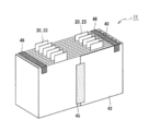
- FIG. 2 is a perspective view of an electrode body which is an example of the embodiment.
- FIG. 3 is a perspective view of an electrode body which is another example of the embodiment.
- FIG. 1 is a perspective view showing the appearance of the secondary battery 10 which is an example of the embodiment
- FIG. 2 is a perspective view of the electrode body 11 constituting the secondary battery 10.
- the secondary battery 10 which is a so-called square battery in which the electrode body 11 is housed in the square outer can 14 will be illustrated, but the outer body of the battery is not limited to the outer can 14, for example, a metal layer and a resin layer. It may be an exterior body composed of a laminated sheet containing.
- a laminated electrode body 11 in which a plurality of positive electrodes and a plurality of negative electrodes are laminated in a structure via a separator will be illustrated, but the electrode body may be a wound type electrode body.
- the secondary battery 10 has an electrode body 11 in which a positive electrode 20 and a negative electrode 30 are laminated via a separator 40, and a bottomed square tubular outer can that houses the electrode body 11. 14 and a sealing plate 15 for closing the opening of the outer can 14.
- the outer can 14 is a flat, substantially rectangular parallelepiped-shaped metal container with one end open in the axial direction, and the sealing plate 15 has an elongated rectangular shape.
- the outer can 14 and the sealing plate 15 are made of, for example, a metal material containing aluminum as a main component.
- the height direction of the outer can 14 is referred to as the "vertical direction" of the secondary battery 10 and each component
- the sealing plate 15 side is referred to as "upper”
- the bottom side of the outer can 14 is referred to as “lower”.
- the direction along the longitudinal direction of the sealing plate 15 is defined as the "lateral direction” of the secondary battery 10 and each component.
- the portion of the electrode body 11 excluding the tubular portion 43 of the separator 40, which will be described later, may be referred to as an “electrode group”.
- the secondary battery 10 includes an electrolyte housed in the outer can 14 together with the electrode body 11.
- the electrolyte may be an aqueous electrolyte, but is preferably a non-aqueous electrolyte.
- the non-aqueous electrolyte includes, for example, a non-aqueous solvent and an electrolyte salt dissolved in the non-aqueous solvent.
- the non-aqueous solvent for example, esters, ethers, nitriles, amides, and a mixed solvent of two or more of these may be used.
- the non-aqueous solvent may contain a halogen substituent in which at least a part of hydrogen in these solvents is substituted with a halogen atom such as fluorine.
- the electrolyte salt for example, a lithium salt such as LiPF 6 is used.
- the electrode body 11 includes a plurality of positive electrodes 20 and 30 negative electrodes, respectively, and has a structure in which the positive electrodes 20 and 30 negative electrodes are alternately laminated one by one via a separator 40.
- the electrode body 11 contains one more negative electrode 30 than the positive electrode 20, and the negative electrodes 30 are arranged on both sides of the electrode group in the stacking direction.
- the separator 40 has a tubular portion 43 that is formed in a tubular shape and constitutes the outermost surface of the electrode body 11. That is, on the outermost surface of the electrode body 11, a separator 40 wound in a tubular shape for one circumference or more exists, and the negative electrodes 30 arranged on both sides in the stacking direction of the electrode group are covered with the separator 40.
- the electrode body 11 has a laminated structure in which one zigzag-folded separator 40 is interposed between the positive electrode 20 and the negative electrode 30. Then, the tubular portion 43 is formed by the one separator 40.
- the separator interposed between the positive electrode and the negative electrode and the separator constituting the outermost surface of the electrode body may be separate bodies, and the electrode body is a plurality of separators arranged one by one between the positive electrode body and the negative electrode body. , And one separator constituting the tubular portion may be included.
- the electrode body 11 has a plurality of positive electrode tabs 23 and a plurality of negative electrode tabs 33 extending toward the sealing plate 15.
- the positive electrode tab 23 is formed by projecting a part of the core of the positive electrode 20
- the negative electrode tab 33 is formed by projecting a part of the core of the negative electrode 30.
- the positive electrode tab 23 and the negative electrode tab 33 face in the same direction, the positive electrode tab 23 is on one end side in the lateral direction of the electrode body 11, and the negative electrode tab 33 is on the other end side in the lateral direction of the electrode body 11. They are laminated and arranged via the separator 40 so as to be located at each position.
- a positive electrode terminal 12 and a negative electrode terminal 13 are attached to the sealing plate 15.
- the positive electrode tab 23 is electrically connected to the positive electrode terminal 12 via a positive electrode current collector (not shown)
- the negative electrode tab 33 is electrically connected to the negative electrode terminal 13 via a negative electrode current collector (not shown).
- the positive electrode terminal 12 and the negative electrode terminal 13 are external connection terminals that are electrically connected to other secondary batteries 10, electronic devices, and the like, and are attached to the sealing plate 15 via an insulating member.
- the sealing plate 15 is generally provided with a liquid injection unit 16 for injecting an electrolytic solution and a gas discharge valve 17 for opening and discharging gas when an abnormality occurs in the battery.
- the positive electrode 20, the negative electrode 30, and the separator 40 constituting the electrode body 11 will be described in detail, in particular, the layer structure and arrangement of the separator 40.
- the positive electrode 20 has a positive electrode core body and a positive electrode mixture layer formed on the surface of the positive electrode core body.
- a foil of a metal stable in the potential range of the positive electrode 20 such as aluminum or an aluminum alloy, a film in which the metal is arranged on the surface layer, or the like can be used.
- the positive electrode mixture layer contains a positive electrode active material, a conductive material, and a binder, and is preferably provided on both sides of the positive electrode core body.
- a positive electrode mixture slurry containing a positive electrode active material, a conductive material, a binder, and the like is applied onto a positive electrode core, the coating film is dried, and then compressed to form a positive electrode mixture layer. It can be manufactured by forming it on both sides of the core body.
- Lithium transition metal composite oxide is used as the positive electrode active material.
- Metallic elements contained in the lithium transition metal composite oxide include Ni, Co, Mn, Al, B, Mg, Ti, V, Cr, Fe, Cu, Zn, Ga, Sr, Zr, Nb, In and Sn. , Ta, W and the like. Above all, it is preferable to contain at least one of Ni, Co and Mn.
- suitable composite oxides include lithium transition metal composite oxides containing Ni, Co and Mn, and lithium transition metal composite oxides containing Ni, Co and Al.
- Examples of the conductive material contained in the positive electrode mixture layer include carbon materials such as carbon black, acetylene black, ketjen black, and graphite.
- Examples of the binder contained in the positive electrode mixture layer include fluororesins such as polytetrafluoroethylene (PTFE) and polyvinylidene fluoride (PVdF), polyacrylonitrile (PAN), polyimide resins, acrylic resins, and polyolefin resins. .. Further, these resins may be used in combination with a cellulose derivative such as carboxymethyl cellulose (CMC) or a salt thereof, polyethylene oxide (PEO), or the like.
- CMC carboxymethyl cellulose
- PEO polyethylene oxide
- the negative electrode 30 has a negative electrode core and a negative electrode mixture layer formed on the surface of the negative electrode core.
- a metal foil such as copper that is stable in the potential range of the negative electrode 30, a film on which the metal is arranged on the surface layer, or the like can be used.
- the negative electrode mixture layer contains a negative electrode active material and a binder, and is preferably formed on both sides of the negative electrode core body.
- a negative electrode mixture slurry containing a negative electrode active material, a binder, and the like is applied to the surface of the negative electrode core, the coating film is dried, and then compressed to form a negative electrode mixture layer of the negative electrode core. It can be produced by forming it on both sides.
- the negative electrode mixture layer contains, for example, a carbon-based active material that reversibly occludes and releases lithium ions as a negative electrode active material.
- Suitable carbon-based active materials are natural graphite such as scaly graphite, massive graphite, earthy graphite, and graphite such as artificial graphite such as massive artificial graphite (MAG) and graphitized mesophase carbon microbeads (MCMB).
- a Si-based active material composed of at least one of Si and a Si-containing compound may be used, or a carbon-based active material and a Si-based active material may be used in combination.
- the binder contained in the negative electrode mixture layer fluororesin, PAN, polyimide, acrylic resin, polyolefin or the like can be used as in the case of the positive electrode 20, but styrene-butadiene rubber (SBR) is used. Is preferable.
- the negative electrode mixture layer preferably further contains CMC or a salt thereof, polyacrylic acid (PAA) or a salt thereof, polyvinyl alcohol (PVA) and the like. Above all, it is preferable to use SBR in combination with CMC or a salt thereof, PAA or a salt thereof.
- the separator 40 As the separator 40, a porous sheet having ion permeability and insulating property is used.
- the separator 40 includes at least two layers having different heat shrinkage rates, that is, a first layer and a second layer having a lower heat shrinkage rate than the first layer.
- the first layer includes a porous resin base material which is a resin layer
- the second layer includes a porous heat-resistant layer containing inorganic particles.
- the heat-resistant layer is formed on one surface of the resin base material.
- the heat shrinkage rate means the degree of shrinkage (change in length) when the separator 40 is heated.
- the heat shrinkage rate of the second layer is smaller than the heat shrinkage rate of the first layer at, for example, 110 ° C. (the temperature at which the electrode body is heated while applying a load to be described later).
- the separator 40 may have a third layer. Further, the separator 40 is composed of a resin having a higher melting point or softening point than the resin constituting the resin base material, for example, aramid resin, polyimide, polyamideimide, etc., instead of the heat-resistant layer or in addition to the heat-resistant layer. It may contain a resin layer having high heat resistance.
- the resin base material functions as a separator by itself.
- a porous film having ion permeability and insulating property is used as the resin base material.
- the thickness of the resin base material is, for example, 1 ⁇ m to 20 ⁇ m, preferably 5 ⁇ m to 15 ⁇ m.
- the material of the resin base material include olefin resins such as polyethylene, polypropylene, and ethylene-propylene copolymers, ethylene, propylene, and other copolymers with ⁇ -olefins.
- the melting point of the resin base material is generally 200 ° C. or lower.
- the heat-resistant layer is composed mainly of inorganic particles.
- the heat-resistant layer is preferably composed of insulating inorganic particles and a binder that binds the particles to each other and the particles and a resin base material.
- the heat-resistant layer has ion permeability and insulating property like the resin base material.
- the thickness of the heat-resistant layer is, for example, 1 ⁇ m to 10 ⁇ m, preferably 1 ⁇ m to 6 ⁇ m.
- the inorganic particles at least one selected from, for example, alumina, boehmite, silica, titania, and zirconia can be used. Above all, it is preferable to use alumina or boehmite.
- the content of the inorganic particles is preferably 85% by mass to 99.9% by mass, more preferably 90% by mass to 99.5% by mass, based on the mass of the heat-resistant layer.
- the binder constituting the heat-resistant layer for example, a fluororesin such as PVdF, SBR, or the same resin as the binder contained in the positive electrode mixture layer and the negative electrode mixture layer can be used.
- the content of the binder is preferably 0.1% by mass to 15% by mass, more preferably 0.5% by mass to 10% by mass, based on the mass of the heat-resistant layer.
- the heat-resistant layer is formed by, for example, applying a slurry containing inorganic particles and a binder to one surface of a resin base material and drying the coating film.
- An adhesive layer that adheres to the surface of the positive electrode 20 or the negative electrode 30 is formed on at least one surface of the separator 40, for example.
- the adhesive layer may be formed on both sides of the separator 40, and in that case, the composition of the adhesive layer may be different between one surface and the other surface.
- An example of the thickness of the adhesive layer is 0.1 ⁇ m to 1 ⁇ m, or 0.2 ⁇ m to 0.9 ⁇ m.
- the adhesive layer is formed, for example, by applying an emulsion adhesive in which the adhesive component is dispersed in water to the surface of the separator 40 and drying the coating film.
- the adhesive layer may be formed in a dot shape, for example.
- the adhesive layer does not have adhesiveness at room temperature (25 ° C.) and develops adhesiveness by heating.
- An example of an adhesive constituting the adhesive layer is an adhesive containing an acrylic resin as a main component.
- the electrode body 11 is manufactured, for example, by laminating the negative electrode 30 / separator 40 with adhesive layer / positive electrode 20 / separator 40 with adhesive layer in this order and undergoing a hot pressing step (thermocompression bonding step). In this heat pressing step, the resin base material may be heated and heat-shrinked.
- the separator 40 is preferably arranged so that the heat-resistant layer faces the positive electrode 20 side. That is, the separator 40 is arranged between the positive electrode 20 and the negative electrode 30 in a state where the resin base material is in contact with the negative electrode 30 and the heat resistant layer is in contact with the positive electrode 20. In this case, oxidative deterioration of the resin base material of the separator 40 due to the positive electrode potential is suppressed as compared with the configuration in which the resin base material faces the positive electrode 20 side.
- heat-resistant layers are arranged on both sides of all the positive electrodes 20.
- the separator 40 is folded in a zigzag manner and is interposed between the positive electrode 20 and the negative electrode 30 and is formed in a tubular shape to form the outermost surface of the electrode body 11.
- the tubular portion 43 of the separator 40 forming the outermost surface of the electrode body 11 is formed by winding the separator 40 in a tubular shape along the side surface of the electrode group for one or more turns so that the side surface of the electrode group is not exposed. Cover the entire side surface.
- the side surface of the electrode group is a surface along the vertical direction of the electrode body 11, and both ends in the stacking direction of the electrode group (in the present embodiment, both ends in the stacking direction of the electrode group in which the opposite positive electrode 20 does not exist).
- the separator 40 is mounted so as to cover the entire mixture layer of the negative electrode 30 arranged on the outermost side in the stacking direction. That is, the separator 40 is wound in a tubular shape on the side surface of the electrode group so that the mixture layer of the negative electrode 30 is not exposed on the outermost surface of the electrode body 11 to form the tubular portion 43.
- the separator 40 is wound around a part of the side surface of the electrode group twice, and the separator 40 is overlapped by two sheets. That is, a part of the tubular portion 43 is composed of a two-layer separator 40, and the remaining portion is composed of a one-layer separator 40.
- a tape 45 for maintaining the shape of the tubular portion 43 is attached to the winding end end of the separator 40 located on the outermost surface of the electrode body 11.
- the tape 45 is attached, for example, from the end of the winding end of the second layer separator 40 located outside the tubular portion 43 to the first layer separator 40 wound inside the winding end.
- the tubular portion 43 may be formed by winding a separator 40 around the side surface of the electrode group for three or more turns and may be composed of three or more layers of separators 40, but is preferably composed of one or two layers of separators 40. ..
- the tubular portion 43 of the separator 40 at least one end in the axial direction (in the present embodiment, one end in the width direction of the separator 40), the one end in the axial direction is provided from one side to the other in the stacking direction of the electrode body 11.
- a pressing tape 46 is attached.
- the tape 46 is attached to the upper end portion which is one end in the axial direction of the tubular portion 43, and the tape 46 is not attached to the lower end which is the other end in the axial direction.
- the width of the separator 40 is larger than the width of the negative electrode 30 (the width of the portion where the negative electrode tab 33 is not formed), and the separator 40 is in a state of being left over at the upper end portion of the tubular portion 43 rather than the lower end portion. ..
- the separator 40 is likely to float and turn up at the upper end of the tubular portion 43, so it is preferable to attach the tape 46 to at least the upper end.
- the tape 46 is attached to the outermost surface of the electrode body 11 on one side in the stacking direction (hereinafter referred to as “front surface of the electrode body 11”) at the upper end of the tubular portion 43, and passes over the electrode body 11. It extends in the stacking direction and is attached to the outermost surface of the electrode body 11 on the other side in the stacking direction (hereinafter, referred to as “rear surface of the electrode body 11”).
- front surface of the electrode body 11 the electrode body 11 is attached to the front surface of the electrode body 11 so as to straddle the separators 40 of the first layer and the second layer, similarly to the tape 45.
- the tape 46 may be extended along the winding end end of the separator 40 to the lower part of the electrode body 11 and also used as the tape 45.
- the tape 46 is attached from the upper end of the front surface of the electrode body 11 to the upper end of the rear surface in a taut state without bending. In this case, since the upper end portion of the tubular portion 43 is pulled inward, floating and turning are less likely to occur.
- the tape 46 covers a part of the upper surface of the electrode body 11 and extends in the stacking direction of the electrode body 11. Further, the tape 46 passes between the positive electrode tab 23 and the negative electrode tab 33, and is arranged at equidistant positions from each of the positive electrode tab 23 and the negative electrode tab 33, for example. It is preferable that the tape 46 is attached so as not to overlap the liquid injection portion 16 in the vertical direction while avoiding the position directly below the liquid injection portion 16.
- the tape 46 may be formed wide as long as it does not interfere with the positive electrode tab 23 and the negative electrode tab 33 and does not overlap the liquid injection portion 16 in the vertical direction.
- the width of the tape 46 is narrower than the width of the tape 45, but the tape 46 may be wider than the tape 45.
- An example of the width of one tape 46 is 10 mm to 20 mm, which is 5% to 30% of the lateral length of the electrode body 11.
- the length of the tape 46 attached to the front surface and the rear surface of the electrode body 11 along the vertical direction is, for example, 5 mm to 15 mm, which is 5% or more of the vertical length of the electrode body 11.
- each of the positive electrode 20 and the negative electrode 30 has a substantially rectangular shape in front view.
- the tape 46 is attached at a position overlapping the central portion of the positive electrode 20 and the negative electrode 30 in the long side direction. Since the separator 40 is most likely to float and turn over at the central portion in the long side direction on the front surface and the rear surface of the electrode body 11, such a sticking form of the tape 46 is to suppress the floating and turning of the separator 40. It is valid.
- one tape 46 may be attached to both sides of the electrode body 11 in the lateral direction at least at one end in the axial direction of the tubular portion 43.
- the tape 46 is attached between the lateral end of the electrode body 11 and the positive electrode tab 23 toward one end in the lateral direction.
- a tape 46 is attached between the other end in the lateral direction of the electrode body 11 and the negative electrode tab 33 toward the other end in the lateral direction.
- the tape 46 is not attached between the positive electrode tab 23 and the negative electrode tab 33, but the tubular portion 43 is attached to the two tapes 46 on both sides of the electrode body 11 in the lateral direction.
- the tape 46 may be attached to the central portion in the lateral direction.
- the number of tapes 46 is not particularly limited, and four or more tapes may be attached, but three or less tapes are preferable from the viewpoint of productivity.
- the tape 46 may be attached to the upper and lower ends of the tubular portion 43, and the attachment form of the tape 46 may be different between the upper end portion and the lower end portion of the tubular portion 43.
- the tapes 45 and 46 are adhesive tapes containing, for example, an insulating resin base material and an adhesive layer. The same tape can be used for the tapes 45 and 46.
- the thickness of the tapes 45 and 46 is, for example, 10 ⁇ m to 60 ⁇ m, preferably 15 ⁇ m to 40 ⁇ m.
- the resin base material may be any as long as it has durability against an electrolyte, and is composed of a resin such as polyester such as polyethylene terephthalate, polypropylene, polyimide, polyphenylene sulfide, polyetherimide, or polyamide.
- the separator 40 is heat-shrinked in the above-mentioned heat pressing process like the conventional separator.
- the tubular portion floats at the axial end portion due to heat shrinkage and is likely to be turned over.
- the separator 40 such floating and turning are suppressed by the tape 46, and the electrode body 11 It is possible to highly prevent the mixture layer of the negative electrode 30 from being exposed on the outermost surface.
- the separator 40 may be heat-shrinked not only by the above-mentioned heat pressing process but also by heat generation during use of the secondary battery 10.
- the separator 40 in the tubular portion 43, the first layer having a large heat shrinkage rate faces the inside of the electrode body 11, and the second layer having a smaller heat shrinkage rate than the first layer faces the outside of the electrode body 11. It is preferable that they are arranged so as to face each other.
- the separator 40 is arranged so that the resin base material faces inward and the heat-resistant layer faces outward.
- the heat-resistant layer functions as a rigid body layer that maintains the shape of the separator 40, and the axial end portion of the tubular portion 43 is prevented from curving outward and turning up. With such an arrangement, the tubular portion 43 floats at the axial end portion, and the turning up is further suppressed.
- Lithium nickel cobalt manganese composite oxide was used as the positive electrode active material.
- the positive electrode active material, acetylene black, and polyvinylidene fluoride (PVdF) are mixed at a solid content mass ratio of 97: 2: 1, and N-methyl-2-pyrrolidone (NMP) is used as a dispersion medium for the positive electrode.
- NMP N-methyl-2-pyrrolidone
- a mixture slurry was prepared.
- a positive electrode mixture slurry was applied to both sides of a positive electrode core made of aluminum foil having a thickness of 13 ⁇ m, leaving a portion to be a positive electrode tab, and the coating film was dried and compressed, and then cut into a predetermined electrode size.
- a positive electrode (76 mm ⁇ 139 mm) having a positive electrode mixture layer (thickness: 62 ⁇ m on one side) formed on both sides of the positive electrode core was obtained.
- the positive electrode is formed with a positive electrode tab having a width of 20 mm in which a part of the core is projected.
- Graphite was used as the negative electrode active material. Negative electrode active material, carboxymethyl cellulose (CMC), and styrene butadiene rubber (SBR) were mixed at a solid content mass ratio of 98: 1: 1 and water was used as a dispersion medium to prepare a negative electrode mixture slurry. .. Next, a negative electrode mixture slurry was applied to both sides of a negative electrode core made of copper foil having a thickness of 8 ⁇ m, leaving a portion to be a negative electrode tab, and the coating film was dried and compressed, and then cut into a predetermined electrode size.
- CMC carboxymethyl cellulose
- SBR styrene butadiene rubber
- a negative electrode (78 mm ⁇ 143 mm) having a negative electrode mixture layer (thickness: 76 ⁇ m on one side) formed on both sides of the negative electrode core was obtained.
- the negative electrode is formed with a negative electrode tab having a width of 18 mm in which a part of the core is projected.
- a polyethylene porous base material having a thickness of 12 ⁇ m is used, and a slurry containing alumina particles and PVdF is applied to one surface of the base material to form a heat-resistant layer having a thickness of 4 ⁇ m to form a porous material.
- a two-layer structure separator (width: 81 mm) composed of the above resin base material and a porous heat-resistant layer was obtained. Further, an adhesive containing an acrylic resin as a main component was applied to both sides of the separator in a dot shape to form an adhesive layer.
- Ethylene carbonate (EC), methyl ethyl carbonate (EMC), and dimethyl carbonate (DMC) were mixed at a volume ratio of 3: 3: 4 (25 ° C., 1 atm).
- a non-aqueous electrolyte solution was prepared by dissolving LiPF 6 in the mixed solvent so as to have a concentration of 1 mol / L.
- Electrode body After forming an electrode group by alternately stacking 35 positive electrodes and 36 negative electrodes one by one through the zigzag-folded separator, a separator is wound around the side surface of the electrode group to form a winding end end. It was fixed with an adhesive tape to obtain a laminated body (electrode body before thermocompression bonding) in which the entire side surface of the electrode group was covered with a separator. The separator is arranged between the positive electrode and the negative electrode so that the heat-resistant layer faces the positive electrode side.
- an adhesive tape having a width of 15 mm was attached to the tubular portion of the separator covering the side surface of the electrode group in a state where the upper end portion of the tubular portion was pressed without bending from the front surface to the rear surface of the laminated body.
- the tape is attached so as to overlap the central portion in the long side direction of the positive electrode and the negative electrode (the central portion in the lateral direction of the laminated body), and the upper and lower sides of the tape attached to the front and rear surfaces of the laminated body.
- the length along the direction was set to 10 mm.
- the laminate was heated for 43 seconds with a hot plate at 110 ° C. while applying a load of 20 kN to the laminate to obtain an electrode body.
- Example 2 As shown in FIG. 3, the electrode body and the secondary battery are the same as in the first embodiment except that one tape is attached to each side of the electrode body in the lateral direction to press the upper end portion of the separator from the front surface to the rear surface.
- Example 1 As shown in Table 1, in the electrode body of Example 1, it was confirmed that the upper end portion of the separator was not lifted, no folds were generated, and the negative electrode plate mixture layer was not exposed on the outermost surface of the electrode body. It was. In the electrode body of Example 2, floating and turning occurred at the central portion in the lateral direction away from the tape, but the degree was so small that the negative electrode mixture layer was not exposed, as in the case of Example 1. , The effect of suppressing the exposure of the negative electrode mixture layer was confirmed. On the other hand, in the electrode body of Comparative Example 1, the upper end portion of the separator was raised and turned up by 90 ° or more, and the negative electrode mixture layer was exposed on the outermost surface of the electrode body.
- Electrode body 12 Positive electrode terminal 13 Negative electrode terminal 14 Exterior can 15 Seal plate 16 Lubrication part 17 Gas discharge valve 20 Positive electrode 23 Positive electrode tab 30 Negative electrode 33 Negative electrode tab 40 Separator 43 Cylindrical part 45, 46 Tape
Landscapes
- Chemical & Material Sciences (AREA)
- Chemical Kinetics & Catalysis (AREA)
- Electrochemistry (AREA)
- General Chemical & Material Sciences (AREA)
- Inorganic Chemistry (AREA)
- Engineering & Computer Science (AREA)
- Manufacturing & Machinery (AREA)
- Composite Materials (AREA)
- Materials Engineering (AREA)
- Secondary Cells (AREA)
Abstract
L'invention concerne une batterie secondaire comprenant un corps d'électrode formé par stratification d'une électrode positive et d'une électrode négative avec un séparateur interposé entre elles. Le séparateur comprend une première couche et une seconde couche ayant un retrait thermique inférieur à celui de la première couche, et possède une partie tubulaire qui est formée sous une forme tubulaire et qui constitue la surface la plus externe du corps d'électrode. La partie tubulaire du séparateur, qui constitue la surface la plus externe du corps d'électrode, a une bande collée sur celle-ci dans au moins une partie d'extrémité dans la direction axiale, la bande pressant la partie d'extrémité dans la direction axiale d'un côté à l'autre côté dans la direction de stratification du corps d'électrode.
Priority Applications (3)
| Application Number | Priority Date | Filing Date | Title |
|---|---|---|---|
| US17/788,083 US20230042848A1 (en) | 2019-12-27 | 2020-12-15 | Secondary battery |
| JP2021567289A JPWO2021131880A1 (fr) | 2019-12-27 | 2020-12-15 | |
| CN202080090340.1A CN114902462A (zh) | 2019-12-27 | 2020-12-15 | 二次电池 |
Applications Claiming Priority (2)
| Application Number | Priority Date | Filing Date | Title |
|---|---|---|---|
| JP2019-237660 | 2019-12-27 | ||
| JP2019237660 | 2019-12-27 |
Publications (1)
| Publication Number | Publication Date |
|---|---|
| WO2021131880A1 true WO2021131880A1 (fr) | 2021-07-01 |
Family
ID=76574563
Family Applications (1)
| Application Number | Title | Priority Date | Filing Date |
|---|---|---|---|
| PCT/JP2020/046642 WO2021131880A1 (fr) | 2019-12-27 | 2020-12-15 | Batterie secondaire |
Country Status (4)
| Country | Link |
|---|---|
| US (1) | US20230042848A1 (fr) |
| JP (1) | JPWO2021131880A1 (fr) |
| CN (1) | CN114902462A (fr) |
| WO (1) | WO2021131880A1 (fr) |
Cited By (1)
| Publication number | Priority date | Publication date | Assignee | Title |
|---|---|---|---|---|
| US20220109204A1 (en) * | 2020-10-02 | 2022-04-07 | American Lithium Energy Corporation | Impact resistant battery cell |
Citations (6)
| Publication number | Priority date | Publication date | Assignee | Title |
|---|---|---|---|---|
| JP2003123843A (ja) * | 2001-10-05 | 2003-04-25 | Sony Corp | 電池及びその製造方法 |
| US20080233474A1 (en) * | 2007-03-19 | 2008-09-25 | Sukjung Son | Rechargeable battery and its fabrication method |
| JP2013145678A (ja) * | 2012-01-13 | 2013-07-25 | Hitachi Maxell Ltd | 非水電解質二次電池 |
| JP2014127242A (ja) * | 2012-12-25 | 2014-07-07 | Hitachi Maxell Ltd | リチウム二次電池 |
| JP2017059395A (ja) * | 2015-09-16 | 2017-03-23 | トヨタ自動車株式会社 | リチウムイオン電池 |
| JP2018018712A (ja) * | 2016-07-28 | 2018-02-01 | 三洋電機株式会社 | 二次電池の製造方法 |
-
2020
- 2020-12-15 US US17/788,083 patent/US20230042848A1/en active Pending
- 2020-12-15 WO PCT/JP2020/046642 patent/WO2021131880A1/fr active Application Filing
- 2020-12-15 JP JP2021567289A patent/JPWO2021131880A1/ja active Pending
- 2020-12-15 CN CN202080090340.1A patent/CN114902462A/zh active Pending
Patent Citations (6)
| Publication number | Priority date | Publication date | Assignee | Title |
|---|---|---|---|---|
| JP2003123843A (ja) * | 2001-10-05 | 2003-04-25 | Sony Corp | 電池及びその製造方法 |
| US20080233474A1 (en) * | 2007-03-19 | 2008-09-25 | Sukjung Son | Rechargeable battery and its fabrication method |
| JP2013145678A (ja) * | 2012-01-13 | 2013-07-25 | Hitachi Maxell Ltd | 非水電解質二次電池 |
| JP2014127242A (ja) * | 2012-12-25 | 2014-07-07 | Hitachi Maxell Ltd | リチウム二次電池 |
| JP2017059395A (ja) * | 2015-09-16 | 2017-03-23 | トヨタ自動車株式会社 | リチウムイオン電池 |
| JP2018018712A (ja) * | 2016-07-28 | 2018-02-01 | 三洋電機株式会社 | 二次電池の製造方法 |
Cited By (1)
| Publication number | Priority date | Publication date | Assignee | Title |
|---|---|---|---|---|
| US20220109204A1 (en) * | 2020-10-02 | 2022-04-07 | American Lithium Energy Corporation | Impact resistant battery cell |
Also Published As
| Publication number | Publication date |
|---|---|
| US20230042848A1 (en) | 2023-02-09 |
| CN114902462A (zh) | 2022-08-12 |
| JPWO2021131880A1 (fr) | 2021-07-01 |
Similar Documents
| Publication | Publication Date | Title |
|---|---|---|
| US10297867B2 (en) | Sheet-laminated lithium ion secondary battery and production method for sheet-laminated lithium ion secondary battery | |
| JP6859059B2 (ja) | リチウムイオン二次電池及びその製造方法 | |
| JP6863710B2 (ja) | 二次電池 | |
| JP2016509338A (ja) | 電極組立体及びこれを含む電気化学素子 | |
| JP4665930B2 (ja) | アノード及びリチウムイオン二次電池 | |
| WO2017077698A1 (fr) | Plaque d'électrode destinée à un dispositif de stockage d'énergie, et dispositif de stockage d'énergie | |
| JP2010225545A (ja) | リチウムイオン二次電池用電極及びリチウムイオン二次電池 | |
| JP6983867B2 (ja) | 非水電解質二次電池 | |
| JP6587157B2 (ja) | 電極組立体及びこれを含む電気化学素子 | |
| KR20140009037A (ko) | 전극조립체 및 이를 포함하는 전기화학소자 | |
| WO2021131879A1 (fr) | Batterie secondaire | |
| JP2016103425A (ja) | 二次電池のつづら折り積層体構造 | |
| WO2014050114A1 (fr) | Batterie secondaire à électrolyte non aqueux | |
| KR20160027364A (ko) | 이차전지용 전극조립체 | |
| WO2021131880A1 (fr) | Batterie secondaire | |
| JP2007123009A (ja) | 巻回型電池 | |
| JP7200117B2 (ja) | 非水電解質二次電池 | |
| JP7454795B2 (ja) | 非水電解質二次電池用電極板及び非水電解質二次電池 | |
| WO2022202395A1 (fr) | Batterie cylindrique | |
| WO2021131877A1 (fr) | Batterie secondaire et son procédé de production | |
| JP7320166B2 (ja) | 二次電池 | |
| US20210226199A1 (en) | Nonaqueous electrolyte secondary battery | |
| WO2021192667A1 (fr) | Corps d'électrode pour batteries rechargeables | |
| WO2021131878A1 (fr) | Batterie secondaire | |
| WO2023210640A1 (fr) | Batterie secondaire |
Legal Events
| Date | Code | Title | Description |
|---|---|---|---|
| 121 | Ep: the epo has been informed by wipo that ep was designated in this application |
Ref document number: 20905057 Country of ref document: EP Kind code of ref document: A1 |
|
| ENP | Entry into the national phase |
Ref document number: 2021567289 Country of ref document: JP Kind code of ref document: A |
|
| NENP | Non-entry into the national phase |
Ref country code: DE |
|
| 122 | Ep: pct application non-entry in european phase |
Ref document number: 20905057 Country of ref document: EP Kind code of ref document: A1 |