WO2021131312A1 - 電気化学式水素ポンプ及びその制御方法 - Google Patents
電気化学式水素ポンプ及びその制御方法 Download PDFInfo
- Publication number
- WO2021131312A1 WO2021131312A1 PCT/JP2020/040479 JP2020040479W WO2021131312A1 WO 2021131312 A1 WO2021131312 A1 WO 2021131312A1 JP 2020040479 W JP2020040479 W JP 2020040479W WO 2021131312 A1 WO2021131312 A1 WO 2021131312A1
- Authority
- WO
- WIPO (PCT)
- Prior art keywords
- anode
- cell
- hydrogen
- cathode
- voltage
- Prior art date
- Legal status (The legal status is an assumption and is not a legal conclusion. Google has not performed a legal analysis and makes no representation as to the accuracy of the status listed.)
- Ceased
Links
Images




Classifications
-
- C—CHEMISTRY; METALLURGY
- C25—ELECTROLYTIC OR ELECTROPHORETIC PROCESSES; APPARATUS THEREFOR
- C25B—ELECTROLYTIC OR ELECTROPHORETIC PROCESSES FOR THE PRODUCTION OF COMPOUNDS OR NON-METALS; APPARATUS THEREFOR
- C25B1/00—Electrolytic production of inorganic compounds or non-metals
- C25B1/01—Products
- C25B1/02—Hydrogen or oxygen
-
- C—CHEMISTRY; METALLURGY
- C25—ELECTROLYTIC OR ELECTROPHORETIC PROCESSES; APPARATUS THEREFOR
- C25B—ELECTROLYTIC OR ELECTROPHORETIC PROCESSES FOR THE PRODUCTION OF COMPOUNDS OR NON-METALS; APPARATUS THEREFOR
- C25B9/00—Cells or assemblies of cells; Constructional parts of cells; Assemblies of constructional parts, e.g. electrode-diaphragm assemblies; Process-related cell features
- C25B9/60—Constructional parts of cells
- C25B9/65—Means for supplying current; Electrode connections; Electric inter-cell connections
-
- C—CHEMISTRY; METALLURGY
- C25—ELECTROLYTIC OR ELECTROPHORETIC PROCESSES; APPARATUS THEREFOR
- C25B—ELECTROLYTIC OR ELECTROPHORETIC PROCESSES FOR THE PRODUCTION OF COMPOUNDS OR NON-METALS; APPARATUS THEREFOR
- C25B9/00—Cells or assemblies of cells; Constructional parts of cells; Assemblies of constructional parts, e.g. electrode-diaphragm assemblies; Process-related cell features
- C25B9/05—Pressure cells
-
- C—CHEMISTRY; METALLURGY
- C01—INORGANIC CHEMISTRY
- C01B—NON-METALLIC ELEMENTS; COMPOUNDS THEREOF; METALLOIDS OR COMPOUNDS THEREOF NOT COVERED BY SUBCLASS C01C
- C01B3/00—Hydrogen; Gaseous mixtures containing hydrogen; Separation of hydrogen from mixtures containing it; Purification of hydrogen; Reversible storage of hydrogen
-
- C—CHEMISTRY; METALLURGY
- C01—INORGANIC CHEMISTRY
- C01B—NON-METALLIC ELEMENTS; COMPOUNDS THEREOF; METALLOIDS OR COMPOUNDS THEREOF NOT COVERED BY SUBCLASS C01C
- C01B3/00—Hydrogen; Gaseous mixtures containing hydrogen; Separation of hydrogen from mixtures containing it; Purification of hydrogen; Reversible storage of hydrogen
- C01B3/50—Separation of hydrogen or hydrogen-containing gases from gaseous mixtures, e.g. purification
- C01B3/56—Separation of hydrogen or hydrogen-containing gases from gaseous mixtures, e.g. purification by contacting with solids; Regeneration of used solids
-
- C—CHEMISTRY; METALLURGY
- C25—ELECTROLYTIC OR ELECTROPHORETIC PROCESSES; APPARATUS THEREFOR
- C25B—ELECTROLYTIC OR ELECTROPHORETIC PROCESSES FOR THE PRODUCTION OF COMPOUNDS OR NON-METALS; APPARATUS THEREFOR
- C25B1/00—Electrolytic production of inorganic compounds or non-metals
- C25B1/01—Products
- C25B1/02—Hydrogen or oxygen
- C25B1/04—Hydrogen or oxygen by electrolysis of water
-
- C—CHEMISTRY; METALLURGY
- C25—ELECTROLYTIC OR ELECTROPHORETIC PROCESSES; APPARATUS THEREFOR
- C25B—ELECTROLYTIC OR ELECTROPHORETIC PROCESSES FOR THE PRODUCTION OF COMPOUNDS OR NON-METALS; APPARATUS THEREFOR
- C25B11/00—Electrodes; Manufacture thereof not otherwise provided for
- C25B11/02—Electrodes; Manufacture thereof not otherwise provided for characterised by shape or form
- C25B11/03—Electrodes; Manufacture thereof not otherwise provided for characterised by shape or form perforated or foraminous
- C25B11/031—Porous electrodes
- C25B11/032—Gas diffusion electrodes
-
- C—CHEMISTRY; METALLURGY
- C25—ELECTROLYTIC OR ELECTROPHORETIC PROCESSES; APPARATUS THEREFOR
- C25B—ELECTROLYTIC OR ELECTROPHORETIC PROCESSES FOR THE PRODUCTION OF COMPOUNDS OR NON-METALS; APPARATUS THEREFOR
- C25B13/00—Diaphragms; Spacing elements
-
- C—CHEMISTRY; METALLURGY
- C25—ELECTROLYTIC OR ELECTROPHORETIC PROCESSES; APPARATUS THEREFOR
- C25B—ELECTROLYTIC OR ELECTROPHORETIC PROCESSES FOR THE PRODUCTION OF COMPOUNDS OR NON-METALS; APPARATUS THEREFOR
- C25B15/00—Operating or servicing cells
- C25B15/02—Process control or regulation
- C25B15/021—Process control or regulation of heating or cooling
-
- C—CHEMISTRY; METALLURGY
- C25—ELECTROLYTIC OR ELECTROPHORETIC PROCESSES; APPARATUS THEREFOR
- C25B—ELECTROLYTIC OR ELECTROPHORETIC PROCESSES FOR THE PRODUCTION OF COMPOUNDS OR NON-METALS; APPARATUS THEREFOR
- C25B15/00—Operating or servicing cells
- C25B15/02—Process control or regulation
- C25B15/023—Measuring, analysing or testing during electrolytic production
-
- C—CHEMISTRY; METALLURGY
- C25—ELECTROLYTIC OR ELECTROPHORETIC PROCESSES; APPARATUS THEREFOR
- C25B—ELECTROLYTIC OR ELECTROPHORETIC PROCESSES FOR THE PRODUCTION OF COMPOUNDS OR NON-METALS; APPARATUS THEREFOR
- C25B15/00—Operating or servicing cells
- C25B15/02—Process control or regulation
- C25B15/023—Measuring, analysing or testing during electrolytic production
- C25B15/025—Measuring, analysing or testing during electrolytic production of electrolyte parameters
- C25B15/027—Temperature
-
- C—CHEMISTRY; METALLURGY
- C25—ELECTROLYTIC OR ELECTROPHORETIC PROCESSES; APPARATUS THEREFOR
- C25B—ELECTROLYTIC OR ELECTROPHORETIC PROCESSES FOR THE PRODUCTION OF COMPOUNDS OR NON-METALS; APPARATUS THEREFOR
- C25B9/00—Cells or assemblies of cells; Constructional parts of cells; Assemblies of constructional parts, e.g. electrode-diaphragm assemblies; Process-related cell features
- C25B9/17—Cells comprising dimensionally-stable non-movable electrodes; Assemblies of constructional parts thereof
- C25B9/19—Cells comprising dimensionally-stable non-movable electrodes; Assemblies of constructional parts thereof with diaphragms
-
- C—CHEMISTRY; METALLURGY
- C25—ELECTROLYTIC OR ELECTROPHORETIC PROCESSES; APPARATUS THEREFOR
- C25B—ELECTROLYTIC OR ELECTROPHORETIC PROCESSES FOR THE PRODUCTION OF COMPOUNDS OR NON-METALS; APPARATUS THEREFOR
- C25B9/00—Cells or assemblies of cells; Constructional parts of cells; Assemblies of constructional parts, e.g. electrode-diaphragm assemblies; Process-related cell features
- C25B9/17—Cells comprising dimensionally-stable non-movable electrodes; Assemblies of constructional parts thereof
- C25B9/19—Cells comprising dimensionally-stable non-movable electrodes; Assemblies of constructional parts thereof with diaphragms
- C25B9/23—Cells comprising dimensionally-stable non-movable electrodes; Assemblies of constructional parts thereof with diaphragms comprising ion-exchange membranes in or on which electrode material is embedded
-
- C—CHEMISTRY; METALLURGY
- C25—ELECTROLYTIC OR ELECTROPHORETIC PROCESSES; APPARATUS THEREFOR
- C25B—ELECTROLYTIC OR ELECTROPHORETIC PROCESSES FOR THE PRODUCTION OF COMPOUNDS OR NON-METALS; APPARATUS THEREFOR
- C25B9/00—Cells or assemblies of cells; Constructional parts of cells; Assemblies of constructional parts, e.g. electrode-diaphragm assemblies; Process-related cell features
- C25B9/60—Constructional parts of cells
-
- B—PERFORMING OPERATIONS; TRANSPORTING
- B01—PHYSICAL OR CHEMICAL PROCESSES OR APPARATUS IN GENERAL
- B01D—SEPARATION
- B01D2256/00—Main component in the product gas stream after treatment
- B01D2256/16—Hydrogen
-
- B—PERFORMING OPERATIONS; TRANSPORTING
- B01—PHYSICAL OR CHEMICAL PROCESSES OR APPARATUS IN GENERAL
- B01D—SEPARATION
- B01D53/00—Separation of gases or vapours; Recovering vapours of volatile solvents from gases; Chemical or biological purification of waste gases, e.g. engine exhaust gases, smoke, fumes, flue gases, aerosols
- B01D53/32—Separation of gases or vapours; Recovering vapours of volatile solvents from gases; Chemical or biological purification of waste gases, e.g. engine exhaust gases, smoke, fumes, flue gases, aerosols by electrical effects other than those provided for in group B01D61/00
- B01D53/326—Separation of gases or vapours; Recovering vapours of volatile solvents from gases; Chemical or biological purification of waste gases, e.g. engine exhaust gases, smoke, fumes, flue gases, aerosols by electrical effects other than those provided for in group B01D61/00 in electrochemical cells
-
- Y—GENERAL TAGGING OF NEW TECHNOLOGICAL DEVELOPMENTS; GENERAL TAGGING OF CROSS-SECTIONAL TECHNOLOGIES SPANNING OVER SEVERAL SECTIONS OF THE IPC; TECHNICAL SUBJECTS COVERED BY FORMER USPC CROSS-REFERENCE ART COLLECTIONS [XRACs] AND DIGESTS
- Y02—TECHNOLOGIES OR APPLICATIONS FOR MITIGATION OR ADAPTATION AGAINST CLIMATE CHANGE
- Y02E—REDUCTION OF GREENHOUSE GAS [GHG] EMISSIONS, RELATED TO ENERGY GENERATION, TRANSMISSION OR DISTRIBUTION
- Y02E60/00—Enabling technologies; Technologies with a potential or indirect contribution to GHG emissions mitigation
- Y02E60/30—Hydrogen technology
- Y02E60/36—Hydrogen production from non-carbon containing sources, e.g. by water electrolysis
-
- Y—GENERAL TAGGING OF NEW TECHNOLOGICAL DEVELOPMENTS; GENERAL TAGGING OF CROSS-SECTIONAL TECHNOLOGIES SPANNING OVER SEVERAL SECTIONS OF THE IPC; TECHNICAL SUBJECTS COVERED BY FORMER USPC CROSS-REFERENCE ART COLLECTIONS [XRACs] AND DIGESTS
- Y02—TECHNOLOGIES OR APPLICATIONS FOR MITIGATION OR ADAPTATION AGAINST CLIMATE CHANGE
- Y02E—REDUCTION OF GREENHOUSE GAS [GHG] EMISSIONS, RELATED TO ENERGY GENERATION, TRANSMISSION OR DISTRIBUTION
- Y02E60/00—Enabling technologies; Technologies with a potential or indirect contribution to GHG emissions mitigation
- Y02E60/30—Hydrogen technology
- Y02E60/50—Fuel cells
Definitions
- This disclosure relates to an electrochemical hydrogen pump and its control method.
- hydrogen gas used as a fuel gas for fuel cell vehicles and the like is compressed to several tens of MPa.
- Hydrogen gas is often produced from water by an electrochemical reaction using a water electrolyzer or the like.
- Patent Document 1 describes a hydrogen purification boosting system in which an electrolyte membrane is provided between an anode and a cathode, and hydrogen is purified and boosted by applying a voltage between the anode and the cathode. ..
- the laminated structure of the anode, the electrolyte membrane and the cathode is referred to as a membrane-electrode assembly (hereinafter, MEA: Membrane Electrode Assembly may be abbreviated).
- MEA Membrane Electrode Assembly may be abbreviated.
- the hydrogen supplied to the anode may contain impurities.
- the hydrogen may be a hydrogen gas secondarily generated from a steel mill or the like, or may be a reformed gas obtained by reforming a city gas.
- the electrochemical hydrogen pump of one aspect of the present disclosure is provided on an electrolyte membrane, an anode provided on one main surface of the electrolyte membrane, and the other main surface of the electrolyte membrane.
- a cell containing a cathode and a voltage applyer for applying a voltage between the anode and the cathode are provided, and the hydrogen-containing gas supplied to the anode by the voltage applyer applying the voltage.
- An electrochemical hydrogen pump that moves the hydrogen inside to the cathode and boosts the pressure.
- a controller that controls the applied voltage of the voltage applyer to increase the current flowing between the anode and the cathode. Be prepared.
- a voltage is applied between the anode and the cathode provided on each main surface of the electrolyte membrane having a pair of main surfaces.
- a voltage is applied between the anode and the cathode provided on each main surface of the electrolyte membrane having a pair of main surfaces.
- the electrochemical hydrogen pump according to one aspect of the present disclosure has an effect that deterioration of the cell can be suppressed more than before.
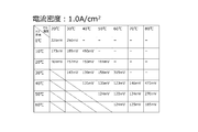
- FIG. 1A is a table showing an example of cell overvoltage when the cell temperature and the gas dew point change respectively when the density of the current flowing between the anode and the cathode is 1.0 A / cm 2.
- FIG. 1B is a table showing an example of cell overvoltage when the cell temperature and the gas dew point change respectively when the density of the current flowing between the anode and the cathode is 1.5 A / cm 2.
- FIG. 1C is a table showing an example of cell overvoltage when the cell temperature and the gas dew point change respectively when the density of the current flowing between the anode and the cathode is 2.0 A / cm 2.
- FIG. 1A is a table showing an example of cell overvoltage when the cell temperature and the gas dew point change respectively when the density of the current flowing between the anode and the cathode is 1.0 A / cm 2.
- FIG. 1B is a table showing an example of cell overvoltage when the cell temperature and the gas dew point change respectively when the density of
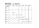
- FIG. 1D is a table showing an example of cell overvoltage when the cell temperature and the gas dew point each change when the density of the current flowing between the anode and the cathode is 2.5 A / cm 2.
- FIG. 2 is a diagram showing an example of an electrochemical hydrogen pump according to the first embodiment.
- FIG. 3 is a diagram showing an example of the correlation between the cell temperature, the proton conductivity (conductivity) of the electrolyte membrane, and the IR loss of the cell.
- FIG. 4 is a diagram showing an example of control of the current flowing between the anode and the cathode in the electrochemical hydrogen pump of the third embodiment of the first embodiment.
- FIG. 5 is a diagram showing an example of an electrochemical hydrogen pump according to the second embodiment.
- Patent Document 1 the possibility of deterioration of the cell of the electrochemical hydrogen pump has not been sufficiently examined.
- the lower the cell temperature and the lower the water content of the electrolyte membrane the lower the proton conductivity of the electrolyte membrane of the cell. That is, the proton conductivity of the electrolyte membrane is represented by the product of the mobility of protons in the electrolyte membrane and the amount of protons moving in the electrolyte membrane. Then, there is a positive correlation between the cell temperature and the mobility of protons in the electrolyte membrane. In addition, there is a positive correlation between the water content in the electrolyte membrane and the amount of protons that move in the electrolyte membrane.
- both the cell temperature and the water content of the electrolyte membrane are often low, so that the proton conductivity of the electrolyte membrane remains low between the anode and the cathode.
- the overvoltage of the cell is more likely to exceed a predetermined voltage than when the current flowing between the anode and the cathode is increased after the proton conductivity of the electrolyte membrane is increased. Conceivable.
- the present disclosures appropriately control the current flowing between the anode and the cathode based on at least one of the dew point of the hydrogen-containing gas supplied to the anode and the temperature of the cell, thereby producing an electrochemical hydrogen. It has been found that the deterioration of the pump cell can be suppressed. Then, such findings were verified by the following experiments.
- the MEA (cell) used in this experiment was prepared by simulating each layer of the MEA of the electrochemical hydrogen pump described in the following embodiment. Therefore, the detailed configuration of the cell will not be described.
- the current flowing between the anode and cathode is four representative values (1.0 A / cm 2 , 1.5 A / cm 2 , 2.0 A / cm 2 , 2.5 A /) in terms of current density.
- cm 2 the overvoltage of the cell when the cell temperature (hereinafter, cell temperature Tc) and the dew point of the low-pressure hydrogen-containing gas supplied to the cell anode (hereinafter, gas dew point Tg) change. was done by measuring.
- the gas pressure on the cathode side was fixed to about 1 MPaG, and the gas pressure on the anode side was fixed to the pressure required for the hydrogen-containing gas at a predetermined flow rate to circulate in the anode.
- the cell overvoltage was measured with a compact wide-range DC power supply (Kikusui Electronics Co., Ltd., PWR1201L).
- the gas dew point Tg is higher than the cell temperature Tc (Tg> Tc)
- the water vapor in the hydrogen-containing gas may condense at the anode of the cell, causing blockage (flooding) of the flow path due to condensed water.
- the diffusibility of the hydrogen-containing gas is hindered by the flooding of the anode, which may lead to an increase in the overvoltage of the cell.
- the overvoltage of the cell becomes a predetermined voltage (set to 500 mV in this experiment) or more, the carbon carrier in the catalyst of the cell is corroded, and the catalyst of the cell is liable to deteriorate.
- FIG. 1A is a table showing an example of cell overvoltage when the cell temperature and the gas dew point change respectively when the density of the current flowing between the anode and the cathode is 1.0 A / cm 2.
- FIG. 1B is a table showing an example of cell overvoltage when the cell temperature and the gas dew point change respectively when the density of the current flowing between the anode and the cathode is 1.5 A / cm 2.
- FIG. 1C is a table showing an example of cell overvoltage when the cell temperature and the gas dew point change respectively when the density of the current flowing between the anode and the cathode is 2.0 A / cm 2.
- FIG. 1D is a table showing an example of cell overvoltage when the cell temperature and the gas dew point each change when the density of the current flowing between the anode and the cathode is 2.5 A / cm 2.
- the area where the measurement result of the cell overvoltage is 500 mV or more is marked with an "X". Further, if the cell temperature Tc is raised without raising the gas dew point or the gas dew point is lowered without lowering the cell temperature from the area marked with "X", the drying-up of the electrolyte membrane of the cell proceeds. To do. As a result, the carbon carrier in the catalyst of the cell is corroded, and the catalyst of the cell is liable to be deteriorated. Therefore, the overvoltage measurement of the cell is stopped. In each table, such unmeasured areas are indicated by "-" marks.
- this experimental result can be inferred from the positive correlation between the proton conductivity of the electrolyte membrane, the cell temperature Tc, and the water content (gas dew point Tg) of the electrolyte membrane. That is, when the gas dew point Tg and the cell temperature Tc are low, the resistance of the electrolyte membrane becomes high.
- the overvoltage of the cell including the IR loss corresponding to the product of the current and the resistance often does not reach the region where the catalyst of the cell deteriorates under the condition that the density of the current flowing between the anode and the cathode is low.
- the overvoltage of the cell often reaches the region where the catalyst of the cell deteriorates.
- the electrochemical hydrogen pump of the first aspect of the present disclosure includes a cell including an anode provided on one main surface of the electrolyte membrane and the electrolyte membrane and a cathode provided on the other main surface of the electrolyte membrane, and an anode.
- a voltage applicator that applies a voltage between the anode and the cathode is provided, and the voltage applicator applies a voltage between the anode and the cathode to obtain hydrogen in the hydrogen-containing gas supplied to the anode.
- An electrochemical hydrogen pump that moves to and boosts the voltage of the anode and cathode by controlling the voltage applied by the voltage applyer when at least one of the dew point of the hydrogen-containing gas supplied to the anode and the temperature of the cell rises. It is equipped with a controller that increases the current flowing between them.
- the electrochemical hydrogen pump of this embodiment can suppress the deterioration of the cell more than before.
- the water content in the electrolyte membrane and the amount of protons moving in the electrolyte membrane have a positive correlation
- the current flowing between the anode and the cathode while the dew point of the hydrogen-containing gas supplied to the anode remains low.
- Increasing the number increases the possibility that the cell's anode will deteriorate due to the increase in cell overvoltage.
- the cell temperature and the mobility of protons in the electrolyte membrane have a positive correlation, if the above current is increased while the cell temperature is low, the overvoltage rise of the cell causes the catalyst of the cell. Is more likely to deteriorate.
- the electrochemical hydrogen pump of this embodiment at least one of the dew point of the hydrogen-containing gas supplied to the anode and the temperature of the cell rises, and then the current flowing between the anode and the cathode is increased, so that these are low. Compared with the case where the above current is increased in the state, the possibility that the overvoltage of the cell reaches the region where the catalyst of the cell is deteriorated can be reduced.
- the electrochemical hydrogen pump of the second aspect of the present disclosure is the electrochemical hydrogen pump of the first aspect, and the controller of the voltage applyer when the dew point of the hydrogen-containing gas supplied to the anode becomes equal to or higher than the first threshold value.
- the applied voltage is controlled to increase the current flowing between the anode and the cathode, and when the dew point of the hydrogen-containing gas supplied to the anode is less than the first threshold, the applied voltage of the voltage applyer is controlled to this. Does not increase the current.
- the electrochemical hydrogen pump of this embodiment appropriately controls the increase or decrease of the current flowing between the anode and the cathode based on the comparison between the dew point of the hydrogen-containing gas supplied to the anode and the first threshold value. Therefore, it is possible to configure the cell so that deterioration of the cell is unlikely to occur.
- the electrochemical hydrogen pump of the third aspect of the present disclosure is the electrochemical hydrogen pump of the first or second aspect, and the controller controls the applied voltage of the voltage applyer when the cell temperature becomes equal to or higher than the second threshold value. To increase the current flowing between the anode and the cathode, and when the cell temperature is below the second threshold, the voltage applied by the voltage applyer is controlled to not increase this current.
- an electrochemical hydrogen pump for example, when controlling the pump so that the relative humidity of the electrolyte membrane and the density of the current flowing between the anode and cathode are constant, the proton conduction of the electrolyte membrane as the cell temperature rises.
- the degree (electricity rate) goes up. Specifically, when the temperature of the cell is equal to or higher than a predetermined temperature, the IR loss of the cell is sufficiently reduced.
- the electrochemical hydrogen pump of this embodiment can improve the efficiency of the hydrogen boosting operation by increasing the current flowing between the anode and the cathode above the second threshold value at which the IR loss of the cell is sufficiently reduced. it can.
- the electrochemical hydrogen pump of this embodiment is configured to prevent deterioration of the cell by appropriately controlling the increase / decrease of the current flowing between the anode and the cathode based on the comparison between the cell temperature and the second threshold value. can do.
- the electrochemical hydrogen pump of the fourth aspect of the present disclosure includes a dew point adjuster for adjusting the dew point of the hydrogen-containing gas supplied to the anode in any one of the first to third aspects of the electrochemical hydrogen pump.
- the controller may control the dew point adjuster to bring the dew point of the hydrogen-containing gas supplied to the anode below the cell temperature.
- the electrochemical hydrogen pump of this embodiment can suppress the deterioration of the cell more than before.
- the dew point of the hydrogen-containing gas supplied to the anode is higher than the cell temperature
- the water vapor in the hydrogen-containing gas condenses at the anode, causing the flow path to be blocked (flooding) by the condensed water. May occur.
- the diffusibility of the hydrogen-containing gas is hindered by the flooding of the anode, which may lead to an increase in the overvoltage of the cell.
- the overvoltage of the cell becomes equal to or higher than a predetermined voltage, the carbon carrier in the catalyst of the cell is corroded, and the cell is liable to deteriorate.
- the occurrence of flooding of the anode is suppressed by controlling the dew point of the hydrogen-containing gas supplied to the anode to be below the cell temperature.
- the electrochemical hydrogen pump according to the fifth aspect of the present disclosure is the electrochemical hydrogen pump according to any one of the first to fourth aspects, in which the controller controls the applied voltage of the voltage applyer to control the voltage between the anode and the cathode. In the period in which the current flowing through the current is increased from 0 to a predetermined value, the lower the current is, the higher the rate of increase in the current may be.
- the electrochemical hydrogen pump of this embodiment can appropriately suppress the deterioration of the cell and rapidly increase the current of the cell. For example, when starting an electrochemical hydrogen pump, both the cell temperature and the water content of the electrolyte membrane are often low. However, even in this case, when the current flowing between the anode and the cathode is low, the rate of increase of the current can be increased without deteriorating the cell, and as a result, the electrochemical hydrogen pump can be started efficiently. Can be done.
- the electrochemical hydrogen pump of the sixth aspect of the present disclosure includes a dew point adjuster for adjusting the dew point of the hydrogen-containing gas supplied to the anode in any one of the first to fifth aspects of the electrochemical hydrogen pump.
- the controller may control the dew point adjuster to raise the dew point of the hydrogen-containing gas supplied to the anode as the temperature of the cell rises.
- the electrochemical hydrogen pump of this embodiment reduces the possibility that the electrolyte membrane dries up as the temperature of the cell rises, as compared with the case where the dew point of the hydrogen-containing gas supplied to the anode is not raised. can do.
- control method of the electrochemical hydrogen pump according to the seventh aspect of the present disclosure is to apply a voltage between the anode and the cathode provided on each main surface of the electrolyte membrane having a pair of main surfaces. At least one of the step of moving the hydrogen in the hydrogen-containing gas supplied to the anode to the cathode to generate compressed hydrogen, the dew point of the hydrogen-containing gas supplied to the anode, and the temperature of the cell rises. Then, the step of controlling the voltage applied between the anode and the cathode to increase the current flowing between the anode and the cathode is provided.
- control method of the electrochemical hydrogen pump of this embodiment can suppress the deterioration of the cell more than before.
- FIG. 2 is a diagram showing an example of an electrochemical hydrogen pump according to the first embodiment.
- the electrochemical hydrogen pump 100 of the present embodiment includes a cell 70, a voltage applyer 102, and a controller 60.
- the electrochemical hydrogen pump 100 may include a stack in which a plurality of cells 70 are stacked. Details will be described later.
- the cell 70 includes an electrolyte membrane 11, an anode AN, and a cathode CA.
- the anode AN is provided on one main surface of the electrolyte membrane 11.
- the anode AN is an electrode including an anode catalyst layer and an anode gas diffusion layer.
- the cathode CA is provided on the other main surface of the electrolyte membrane 11.
- the cathode CA is an electrode including a cathode catalyst layer and a cathode gas diffusion layer.
- the electrolyte membrane 11 may have any structure as long as it has proton conductivity.
- examples of the electrolyte membrane 11 include a fluorine-based polymer electrolyte membrane and a hydrocarbon-based electrolyte membrane.
- the electrolyte membrane 11 for example, Nafion (registered trademark, manufactured by DuPont), Aciplex (registered trademark, manufactured by Asahi Kasei Corporation) and the like can be used, but the electrolyte membrane 11 is not limited thereto.
- the anode catalyst layer is provided on one main surface of the electrolyte membrane 11.
- the anode catalyst layer contains, but is not limited to, carbon capable of carrying a catalyst metal (eg, platinum) in a dispersed state.
- the cathode catalyst layer is provided on the other main surface of the electrolyte membrane 11.
- the cathode catalyst layer contains, but is not limited to, carbon capable of supporting a catalyst metal (eg, platinum) in a dispersed state.
- the method for preparing the catalyst for both the cathode catalyst layer and the anode catalyst layer various methods can be mentioned, but the method is not particularly limited.
- examples of the carbon-based powder include powders such as graphite, carbon black, and conductive activated carbon.
- the method of supporting platinum or other catalytic metal on the carbon carrier is not particularly limited.
- a method such as powder mixing or liquid phase mixing may be used.
- Examples of the latter liquid phase mixing include a method in which a carrier such as carbon is dispersed in a colloidal solution of a catalyst component and adsorbed.
- the supported state of the catalyst metal such as platinum on the carbon carrier is not particularly limited.
- the catalyst metal may be made into fine particles and supported on a carrier with high dispersion.
- the cathode gas diffusion layer is provided on the cathode catalyst layer.
- the cathode gas diffusion layer is made of a porous material and has conductivity and gas diffusivity. It is desirable that the cathode gas diffusion layer has elasticity so as to appropriately follow the displacement and deformation of the constituent members generated by the differential pressure between the cathode CA and the anode AN during the operation of the electrochemical hydrogen pump 100.
- As the base material of the cathode gas diffusion layer for example, a carbon fiber sintered body or the like can be used, but the substrate is not limited thereto.
- the anode gas diffusion layer is provided on the anode catalyst layer.
- the anode gas diffusion layer is made of a porous material and has conductivity and gas diffusivity. It is desirable that the anode gas diffusion layer has a rigidity sufficient to withstand the pressing of the electrolyte membrane 11 due to the above differential pressure during the operation of the electrochemical hydrogen pump 100.
- a carbon particle sintered body or the like can be used, but the substrate is not limited thereto.
- the voltage applyer 102 is a device that applies a voltage between the anode AN and the cathode CA.
- the voltage applyer 102 may have any configuration as long as a voltage can be applied between the anode AN and the cathode CA.
- the high potential side terminal of the voltage applyer 102 is connected to the anode AN
- the low potential side terminal of the voltage applyer 102 is connected to the cathode CA.
- energization is performed between the anode AN and the cathode CA using the voltage applyer 102.
- the voltage applyer 102 applies a voltage between the anode AN and the cathode CA to obtain hydrogen in the hydrogen-containing gas supplied to the anode AN as a cathode. Move to CA and boost.
- Examples of the voltage applyer 102 include a DC / DC converter and an AC / DC converter.
- the DC / DC converter is used when the voltage applyer 102 is connected to a DC power source such as a solar cell, a fuel cell, or a battery.
- the AC / DC converter is used when the voltage applyer 102 is connected to an AC power source such as a commercial power source.
- the voltage applied between the anode AN and the cathode CA and the current flowing between the anode AN and the cathode CA are adjusted so that the electric power supplied to the cell 70 becomes a predetermined set value. It may be a power type power supply.
- the controller 60 controls the applied voltage of the voltage applyer 102 to reduce the current flowing between the anode AN and the cathode CA. increase.
- the controller 60 includes, for example, an arithmetic circuit (not shown) and a storage circuit (not shown) for storing a control program.
- Examples of the arithmetic circuit include an MPU and a CPU.
- Examples of the storage circuit include a memory and the like.
- the controller 60 may be composed of a single controller that performs centralized control, or may be composed of a plurality of controllers that perform distributed control in cooperation with each other.
- each of the pair of separators may sandwich each of the anode AN and the cathode CA of the cell 70 from the outside.
- the separator in contact with the anode AN is a conductive plate-shaped member for supplying the hydrogen-containing gas to the anode AN.
- This plate-shaped member includes a gas flow path through which a hydrogen-containing gas supplied to the anode AN flows.
- the separator in contact with the cathode CA is a conductive plate-shaped member for deriving hydrogen from the cathode CA.
- This plate-shaped member includes a gas flow path through which hydrogen derived from the cathode CA flows.
- sealing materials such as gaskets are usually provided from both sides of the cell 70 so that high-pressure hydrogen does not leak to the outside, and the pump 100 is integrated with the cell 70 and assembled in advance. Then, on the outside of the cell 70, the above-mentioned separator for mechanically fixing the cell 70 and electrically connecting the adjacent cells 70 to each other in series is arranged.
- the cells 70 and the separator are alternately stacked, and about 10 to 200 cells 70 are laminated, the laminated body (stack) is sandwiched between the end plates via the current collector plate and the insulating plate, and the both end plates are fastened rods.
- It is a general laminated structure that is tightened with.
- a groove-shaped branch path is branched from an appropriate conduit in each of the separators, and the downstream ends thereof are the separators. It is necessary to configure it so as to be connected to each gas flow path of.
- Such a pipeline is called a manifold, and this manifold is composed of a series of through holes provided at appropriate positions of the separator.
- the electrochemical hydrogen pump 100 includes a temperature detector that detects the temperature of the cell 70, a temperature controller that adjusts the temperature of the cell 70, a dew point adjuster that adjusts the dew point of the hydrogen-containing gas supplied to the anode AN, and the like. May be provided. The details of the dew point adjuster will be described in the second embodiment.
- thermocouples examples include, but are not limited to, thermocouples, thermistors, and the like.
- the temperature regulator for example, a device for circulating a heat medium having an appropriate temperature in a flow path formed in a separator can be mentioned, but the temperature is not limited to this.
- the temperature controller may be a combination of a heater that heats the cell 70 (for example, an electric heater) and a cooler that cools the cell 70 (for example, a cooling fan).
- the following operations may be performed, for example, by the arithmetic circuit of the controller 60 reading a control program from the storage circuit of the controller 60. However, it is not always essential that the controller 60 performs the following operations. The operator may perform some of the operations.
- a low-pressure hydrogen-containing gas is supplied to the anode AN of the electrochemical hydrogen pump 100, and the voltage of the voltage adapter 102 is supplied to the electrochemical hydrogen pump 100.
- Equation (2) hydrogen molecules are generated again in the cathode catalyst layer (Equation (2)). It is known that when protons conduct through the electrolyte membrane 11, a predetermined amount of water moves from the anode AN to the cathode CA as electroosmotic water along with the protons.
- hydrogen (H 2 ) generated by the cathode CA can be boosted by increasing the pressure loss of the hydrogen derivation path by using a flow rate regulator (not shown).
- the flow rate regulator include a back pressure valve and a regulating valve provided in the hydrogen derivation path.
- increasing the pressure loss in the hydrogen derivation path corresponds to reducing the opening degree of the back pressure valve and the regulating valve provided in the hydrogen derivation path.
- the hydrogen boosted by the cathode CA is temporarily stored in a hydrogen reservoir (not shown), for example. Further, the hydrogen stored in the hydrogen reservoir is supplied to the hydrogen consumer in a timely manner.
- hydrogen demanders include fuel cells that generate electricity using hydrogen.
- the electrochemical hydrogen pump 100 of the present embodiment can suppress the deterioration of the cell 70 more than before.
- the anode AN and CA remain at a low dew point of the hydrogen-containing gas supplied to the anode AN.
- Increasing the current flowing between the cathodes increases the possibility that the catalyst in the cell 70 will deteriorate due to the overvoltage rise in the cell 70.
- the temperature of the cell 70 and the mobility of the protons in the electrolyte membrane 11 have a positive correlation, if the above current is increased while the temperature of the cell 70 is low, the overvoltage of the cell 70 rises. , There is a high possibility that the catalyst in the cell 70 will deteriorate.
- the electrochemical hydrogen pump 100 of the present embodiment increases the current flowing between the anode AN and the cathode CA after at least one of the dew point of the hydrogen-containing gas supplied to the anode AN and the temperature of the cell 70 rises. As a result, it is possible to reduce the possibility that the overvoltage of the cell reaches the region where the catalyst of the cell 70 is deteriorated, as compared with the case where the current is increased while these are in a low state.
- the electrochemical hydrogen pump 100 of the first embodiment is the same as the electrochemical hydrogen pump 100 of the first embodiment except for the control contents of the controller 60 described below.
- the controller 60 controls the applied voltage of the voltage applyr 102 to increase the current flowing between the anode AN and the cathode CA.
- the applied voltage of the voltage applyer 102 is controlled so that this current is not increased.
- the first threshold value is, for example, the cell of the electrochemical hydrogen pump by referring to the tables shown in FIGS. 1A to 1D based on the operating conditions such as the amount of hydrogen boosted by the electrochemical hydrogen pump. It can be set to an appropriate value at which deterioration of the above is unlikely to occur.
- the electrochemical hydrogen pump 100 of the present embodiment appropriately increases or decreases the current flowing between the anode AN and the cathode CA based on the comparison between the dew point of the hydrogen-containing gas supplied to the anode AN and the first threshold value.
- the cell 70 can be configured to be less likely to deteriorate.
- the electrochemical hydrogen pump 100 of this embodiment may be the same as the electrochemical hydrogen pump 100 of the first embodiment except for the above-mentioned features.
- the electrochemical hydrogen pump 100 of the second embodiment is the same as the electrochemical hydrogen pump 100 of the first embodiment except for the control contents of the controller 60 described below.
- FIG. 3 is a diagram showing an example of the correlation between the cell temperature, the proton conductivity (conductivity) of the electrolyte membrane, and the IR loss of the cell.
- the temperature of the cell 70 is taken on the horizontal axis of FIG. Further, the vertical axis on the left side of FIG. 3 shows the proton conductivity of the electrolyte membrane 11, and the vertical axis on the right side shows the IR loss of the cell 70.
- FIG. 3 shows the above correlation when the relative humidity of the electrolyte membrane 11 and the density of the current flowing between the anode AN and the cathode CA are constant.
- the relative humidity of the electrolyte membrane 11 can be maintained constant by increasing or decreasing the dew point of the hydrogen-containing gas as the temperature of the cell 70 increases or decreases.
- the temperature of the cell 70 is controlled. As the temperature increases, the proton conductivity (electricity) of the electrolyte membrane 11 increases. Specifically, it can be seen that when the temperature of the cell 70 is equal to or higher than a predetermined temperature, the IR loss of the cell 70 is sufficiently reduced.
- the controller 60 controls the applied voltage of the voltage applyer 102 to increase the current flowing between the anode AN and the cathode CA, and the temperature of the cell 70.
- the applied voltage of the voltage applyer 102 is controlled so that this current is not increased.
- the electrochemical hydrogen pump 100 of the present embodiment operates the hydrogen boosting operation by increasing the current flowing between the anode AN and the cathode CA above the second threshold value at which the IR loss of the cell 70 sufficiently decreases. Efficiency can be improved.
- the second threshold value takes into consideration the correlation between the temperature of the cell 70 and the IR loss of the cell 70, for example, based on the operating conditions such as the amount of hydrogen boosted by the electrochemical hydrogen pump. Therefore, it is possible to set an appropriate value that improves the efficiency of the hydrogen boosting operation of the electrochemical hydrogen pump 100.
- the electrochemical hydrogen pump 100 of the present embodiment appropriately controls the increase / decrease of the current flowing between the anode AN and the cathode CA based on the comparison between the temperature of the cell 70 and the second threshold value, so that the cell 70 It can be configured so that deterioration of the above does not easily occur.
- the second threshold value of the electrochemical hydrogen pump can be determined by referring to the tables shown in FIGS. 1A to 1D based on the operating conditions such as the amount of hydrogen boosted by the electrochemical hydrogen pump. It can be set to an appropriate value at which cell deterioration is unlikely to occur.
- the electrochemical hydrogen pump 100 of this embodiment may be the same as the electrochemical hydrogen pump 100 of the first embodiment of the first embodiment or the first embodiment except for the above-mentioned features.
- the electrochemical hydrogen pump 100 of the third embodiment is the same as the electrochemical hydrogen pump 100 of the first embodiment except for the control contents of the controller 60 described below.
- FIG. 4 is a diagram showing an example of control of the current flowing between the anode and the cathode in the electrochemical hydrogen pump of the third embodiment of the first embodiment.
- the period for increasing the current flowing between the anode AN and the cathode CA at the time of starting from 0 to a predetermined value is set to n sub-periods (s1, It is divided into s2, ..., Sn: n is a natural number), and the current increments in each of the n sub-periods are f1, f2, ..., Fn (n is a natural number).
- fx / sx: x is a natural number represented by 1 ⁇ x ⁇ n). Then, when defining the lower current ratio as the first ratio and the higher current ratio as the second ratio among any two ratios selected from the n ratios rx, the second ratio is larger than the first ratio.
- the applied voltage of the voltage applicator 102 is controlled so as to be small.
- the applied voltage of the voltage applicator 102 is controlled so as to be.
- the controller 60 controls the applied voltage of the voltage applyer 102 to raise the current flowing between the anode AN and the cathode CA from 0 to a predetermined value. The lower the current, the higher the rate of increase in the current.
- the electrochemical hydrogen pump 100 of this embodiment can appropriately suppress the deterioration of the cell 70 and rapidly increase the current of the cell 70.
- both the temperature of the cell 70 and the water content of the electrolyte membrane 11 are often low.
- the rate of increase in the current can be increased without deteriorating the cell 70, and as a result, the electrochemical hydrogen pump 100 can be efficiently used. Can be started in.
- the electrochemical hydrogen pump 100 of this embodiment is the same as the electrochemical hydrogen pump 100 of any one of the first embodiment and the first embodiment-the second embodiment except for the above-mentioned features. May be good.
- FIG. 5 is a diagram showing an example of an electrochemical hydrogen pump according to the second embodiment.
- the electrochemical hydrogen pump 100 of the present embodiment includes a cell 70, a voltage applyer 102, a dew point adjuster 110, and a controller 60.
- the dew point adjuster 110 is a device that adjusts the dew point of the hydrogen-containing gas supplied to the anode AN.
- the dew point adjuster 110 may have any configuration as long as the dew point of such a hydrogen-containing gas can be adjusted.
- the dew point adjuster 110 may include a humidifier that humidifies a hydrogen-containing gas.
- the humidifier include a humidifier having a bubbler structure in which hydrogen-containing gas is aerated in hot water to humidify the humidifier, and a humidifier having a structure in which the hydrogen-containing gas is humidified with a moisture permeable membrane.
- the dew point adjuster 110 includes the humidifier having the above bubbler configuration, the dew point of the hydrogen-containing gas can be appropriately adjusted depending on the temperature of the hot water.
- the dew point adjuster 110 mixes the highly humidified hydrogen-containing gas discharged from the anode AN with the low-humidified hydrogen-containing gas supplied from the external hydrogen supply source to obtain the dew point of the mixed gas. It may be a mixer that adjusts.
- the hydrogen-containing gas of the external hydrogen supply source may be generated by, for example, a water electrolyzer.
- the controller 60 controls the dew point adjuster 110 to bring the dew point of the hydrogen-containing gas supplied to the anode AN to the temperature of the cell 70 or less.
- the electrochemical hydrogen pump 100 of the present embodiment can suppress the deterioration of the cell 70 more than before. Specifically, when the dew point of the hydrogen-containing gas supplied to the anode AN is higher than the temperature of the cell 70, the water vapor in the hydrogen-containing gas is condensed in the anode AN, so that the flow path is blocked by the condensed water ( Flooding) may occur. Then, the diffusivity of the hydrogen-containing gas is hindered by the flooding of the anode AN, which may lead to an increase in the overvoltage of the cell 70. Then, when the overvoltage of the cell 70 becomes equal to or higher than a predetermined voltage, the carbon carrier in the catalyst of the cell 70 is corroded, and the cell 70 is likely to be deteriorated.
- the dew point of the hydrogen-containing gas supplied to the anode AN is controlled to be equal to or lower than the temperature of the cell 70, so that the occurrence of flooding of the anode AN is suppressed.
- the electrochemical hydrogen pump 100 of the present embodiment is the same as the electrochemical hydrogen pump 100 of any of the first embodiment and the first embodiment to the third embodiment except for the above-mentioned features. May be good.
- the electrochemical hydrogen pump 100 of this modification is the same as the electrochemical hydrogen pump 100 of the second embodiment except for the control contents of the controller 60 described below.
- the controller 60 controls the dew point adjuster 110 to raise the dew point of the hydrogen-containing gas supplied to the anode AN in response to the rise in the temperature of the cell 70.
- the electrolyte membrane 11 can be dried up as the temperature of the cell 70 rises, as compared with the case where the dew point of the hydrogen-containing gas supplied to the anode AN is not raised.
- the sex can be reduced.
- the electrochemical hydrogen pump 100 of this modification is any of the first embodiment, the first embodiment-third embodiment, and the second embodiment of the first embodiment and the first embodiment. May be similar to.
- first embodiment, the first embodiment, the third embodiment, the second embodiment, and the modified examples of the second embodiment may be combined with each other as long as the other party is not excluded from each other.
- One aspect of the present disclosure can be used for an electrochemical hydrogen pump that can suppress deterioration of cells more than before.
- Electrolyte membrane 60 Controller 70: Cell 100: Electrochemical hydrogen pump 102: Voltage applyer 110: Dew point adjuster AN: Anode CA: Cathode
Landscapes
- Chemical & Material Sciences (AREA)
- Engineering & Computer Science (AREA)
- Organic Chemistry (AREA)
- Metallurgy (AREA)
- Chemical Kinetics & Catalysis (AREA)
- Electrochemistry (AREA)
- Materials Engineering (AREA)
- Inorganic Chemistry (AREA)
- Automation & Control Theory (AREA)
- Analytical Chemistry (AREA)
- Combustion & Propulsion (AREA)
- Fuel Cell (AREA)
- Electrolytic Production Of Non-Metals, Compounds, Apparatuses Therefor (AREA)
- Sowing (AREA)
Priority Applications (4)
| Application Number | Priority Date | Filing Date | Title |
|---|---|---|---|
| CN202080012135.3A CN113366152B (zh) | 2019-12-24 | 2020-10-28 | 电化学式氢泵及其控制方法 |
| EP20906188.6A EP4083266A4 (en) | 2019-12-24 | 2020-10-28 | ELECTROCHEMICAL HYDROGEN PUMP AND ITS CONTROL METHOD |
| JP2021531738A JP7002044B2 (ja) | 2019-12-24 | 2020-10-28 | 電気化学式水素ポンプ及びその制御方法 |
| US17/498,314 US20220025529A1 (en) | 2019-12-24 | 2021-10-11 | Electrochemical hydrogen pump and method for controlling the same |
Applications Claiming Priority (2)
| Application Number | Priority Date | Filing Date | Title |
|---|---|---|---|
| JP2019-232399 | 2019-12-24 | ||
| JP2019232399 | 2019-12-24 |
Related Child Applications (1)
| Application Number | Title | Priority Date | Filing Date |
|---|---|---|---|
| US17/498,314 Continuation US20220025529A1 (en) | 2019-12-24 | 2021-10-11 | Electrochemical hydrogen pump and method for controlling the same |
Publications (1)
| Publication Number | Publication Date |
|---|---|
| WO2021131312A1 true WO2021131312A1 (ja) | 2021-07-01 |
Family
ID=76574053
Family Applications (1)
| Application Number | Title | Priority Date | Filing Date |
|---|---|---|---|
| PCT/JP2020/040479 Ceased WO2021131312A1 (ja) | 2019-12-24 | 2020-10-28 | 電気化学式水素ポンプ及びその制御方法 |
Country Status (5)
| Country | Link |
|---|---|
| US (1) | US20220025529A1 (https=) |
| EP (1) | EP4083266A4 (https=) |
| JP (1) | JP7002044B2 (https=) |
| CN (1) | CN113366152B (https=) |
| WO (1) | WO2021131312A1 (https=) |
Families Citing this family (3)
| Publication number | Priority date | Publication date | Assignee | Title |
|---|---|---|---|---|
| CN111417746B9 (zh) * | 2018-11-05 | 2024-07-05 | 松下知识产权经营株式会社 | 电化学式氢压缩装置和电化学式氢压缩装置的运行方法 |
| FR3136780B1 (fr) | 2022-06-16 | 2024-08-02 | H2Gremm | Procédé de production d’hydrogène avec réglage de la puissance d’un compresseur |
| GB2633564A (en) * | 2023-09-12 | 2025-03-19 | Ceres Ip Co Ltd | Method for transitioning load in an electrolyser |
Citations (9)
| Publication number | Priority date | Publication date | Assignee | Title |
|---|---|---|---|---|
| JPS5974288A (ja) * | 1982-09-20 | 1984-04-26 | オリン・コ−ポレイシヨン | 自動化された膜テストセル装置およびその使用方法 |
| JPS627886A (ja) * | 1985-07-02 | 1987-01-14 | エナジ−・リサ−チ・コ−ポレ−シヨン | 水素精製方法及び装置 |
| US20090136790A1 (en) * | 2007-11-13 | 2009-05-28 | Schrieber Jeffrey W | Regulating An Oxidizer In An Electrochemical Cell Pumping System |
| JP2017529460A (ja) * | 2014-07-02 | 2017-10-05 | ヌヴェラ・フュエル・セルズ,エルエルシー | マルチスタック電気化学的圧縮機システムおよび作動方法 |
| WO2018033948A1 (ja) * | 2016-08-18 | 2018-02-22 | 株式会社 東芝 | 水素製造システム及び電解セルスタックの制御方法 |
| JP6299027B2 (ja) | 2013-12-16 | 2018-03-28 | 国立大学法人山梨大学 | 水素精製昇圧システム及びその運転方法 |
| JP2018165386A (ja) * | 2017-03-28 | 2018-10-25 | 東京瓦斯株式会社 | 圧縮水素製造システム |
| JP2019014644A (ja) * | 2017-07-05 | 2019-01-31 | パナソニックIpマネジメント株式会社 | 水素供給システム |
| JP2019183258A (ja) * | 2018-04-16 | 2019-10-24 | パナソニックIpマネジメント株式会社 | 電気化学式水素ポンプおよび電気化学式水素ポンプの運転方法 |
Family Cites Families (5)
| Publication number | Priority date | Publication date | Assignee | Title |
|---|---|---|---|---|
| AU2015284224B2 (en) * | 2014-07-03 | 2019-05-16 | Nuvera Fuel Cells, LLC | System and method for regenerating absorber bed for drying compressed humidified hydrogen |
| JP6979626B2 (ja) * | 2017-08-04 | 2021-12-15 | パナソニックIpマネジメント株式会社 | 水素供給システム |
| JP7220368B2 (ja) * | 2017-12-01 | 2023-02-10 | パナソニックIpマネジメント株式会社 | 水素供給システム |
| JP2019119654A (ja) * | 2018-01-10 | 2019-07-22 | パナソニックIpマネジメント株式会社 | 電気化学式水素ポンプ |
| JP7162258B2 (ja) * | 2018-05-30 | 2022-10-28 | パナソニックIpマネジメント株式会社 | 水素供給システムおよび水素供給システムの運転方法 |
-
2020
- 2020-10-28 CN CN202080012135.3A patent/CN113366152B/zh active Active
- 2020-10-28 JP JP2021531738A patent/JP7002044B2/ja active Active
- 2020-10-28 WO PCT/JP2020/040479 patent/WO2021131312A1/ja not_active Ceased
- 2020-10-28 EP EP20906188.6A patent/EP4083266A4/en not_active Withdrawn
-
2021
- 2021-10-11 US US17/498,314 patent/US20220025529A1/en not_active Abandoned
Patent Citations (9)
| Publication number | Priority date | Publication date | Assignee | Title |
|---|---|---|---|---|
| JPS5974288A (ja) * | 1982-09-20 | 1984-04-26 | オリン・コ−ポレイシヨン | 自動化された膜テストセル装置およびその使用方法 |
| JPS627886A (ja) * | 1985-07-02 | 1987-01-14 | エナジ−・リサ−チ・コ−ポレ−シヨン | 水素精製方法及び装置 |
| US20090136790A1 (en) * | 2007-11-13 | 2009-05-28 | Schrieber Jeffrey W | Regulating An Oxidizer In An Electrochemical Cell Pumping System |
| JP6299027B2 (ja) | 2013-12-16 | 2018-03-28 | 国立大学法人山梨大学 | 水素精製昇圧システム及びその運転方法 |
| JP2017529460A (ja) * | 2014-07-02 | 2017-10-05 | ヌヴェラ・フュエル・セルズ,エルエルシー | マルチスタック電気化学的圧縮機システムおよび作動方法 |
| WO2018033948A1 (ja) * | 2016-08-18 | 2018-02-22 | 株式会社 東芝 | 水素製造システム及び電解セルスタックの制御方法 |
| JP2018165386A (ja) * | 2017-03-28 | 2018-10-25 | 東京瓦斯株式会社 | 圧縮水素製造システム |
| JP2019014644A (ja) * | 2017-07-05 | 2019-01-31 | パナソニックIpマネジメント株式会社 | 水素供給システム |
| JP2019183258A (ja) * | 2018-04-16 | 2019-10-24 | パナソニックIpマネジメント株式会社 | 電気化学式水素ポンプおよび電気化学式水素ポンプの運転方法 |
Non-Patent Citations (1)
| Title |
|---|
| See also references of EP4083266A4 |
Also Published As
| Publication number | Publication date |
|---|---|
| JP7002044B2 (ja) | 2022-02-04 |
| EP4083266A4 (en) | 2024-11-13 |
| CN113366152B (zh) | 2025-03-07 |
| CN113366152A (zh) | 2021-09-07 |
| EP4083266A1 (en) | 2022-11-02 |
| JPWO2021131312A1 (https=) | 2021-07-01 |
| US20220025529A1 (en) | 2022-01-27 |
Similar Documents
| Publication | Publication Date | Title |
|---|---|---|
| JP6765060B1 (ja) | 電気化学式水素圧縮装置および電気化学式水素圧縮装置の運転方法 | |
| JP7122541B2 (ja) | 電気化学式水素ポンプおよび電気化学式水素ポンプの運転方法 | |
| JP6893310B2 (ja) | 水素システム | |
| CN110344072A (zh) | 氢气供给系统 | |
| JP7002044B2 (ja) | 電気化学式水素ポンプ及びその制御方法 | |
| JP6956392B1 (ja) | 圧縮装置 | |
| US20240060190A1 (en) | Electrochemical cell for hydrogen pump and compression apparatus | |
| JP2020090695A (ja) | 電気化学式水素圧縮システム | |
| JP7142231B1 (ja) | 圧縮装置および圧縮装置の制御方法 | |
| JP7142309B1 (ja) | 圧縮装置および圧縮装置の制御方法 | |
| WO2021240875A1 (ja) | 水素システム | |
| JP7345104B1 (ja) | 圧縮装置 | |
| WO2022224480A1 (ja) | 圧縮装置および圧縮装置の制御方法 | |
| WO2022224481A1 (ja) | 圧縮装置および圧縮装置の制御方法 | |
| WO2022097348A1 (ja) | 水素システムおよび水素システムの運転方法 |
Legal Events
| Date | Code | Title | Description |
|---|---|---|---|
| ENP | Entry into the national phase |
Ref document number: 2021531738 Country of ref document: JP Kind code of ref document: A |
|
| 121 | Ep: the epo has been informed by wipo that ep was designated in this application |
Ref document number: 20906188 Country of ref document: EP Kind code of ref document: A1 |
|
| NENP | Non-entry into the national phase |
Ref country code: DE |
|
| ENP | Entry into the national phase |
Ref document number: 2020906188 Country of ref document: EP Effective date: 20220725 |
|
| WWG | Wipo information: grant in national office |
Ref document number: 202080012135.3 Country of ref document: CN |
|
| WWW | Wipo information: withdrawn in national office |
Ref document number: 2020906188 Country of ref document: EP |