WO2021130910A1 - 熱交換器ユニット及び冷凍サイクル装置 - Google Patents
熱交換器ユニット及び冷凍サイクル装置 Download PDFInfo
- Publication number
- WO2021130910A1 WO2021130910A1 PCT/JP2019/050872 JP2019050872W WO2021130910A1 WO 2021130910 A1 WO2021130910 A1 WO 2021130910A1 JP 2019050872 W JP2019050872 W JP 2019050872W WO 2021130910 A1 WO2021130910 A1 WO 2021130910A1
- Authority
- WO
- WIPO (PCT)
- Prior art keywords
- heat exchanger
- heat transfer
- heat
- transfer members
- refrigerant
- Prior art date
- Legal status (The legal status is an assumption and is not a legal conclusion. Google has not performed a legal analysis and makes no representation as to the accuracy of the status listed.)
- Ceased
Links
Images


Classifications
-
- F—MECHANICAL ENGINEERING; LIGHTING; HEATING; WEAPONS; BLASTING
- F28—HEAT EXCHANGE IN GENERAL
- F28F—DETAILS OF HEAT-EXCHANGE AND HEAT-TRANSFER APPARATUS, OF GENERAL APPLICATION
- F28F1/00—Tubular elements; Assemblies of tubular elements
- F28F1/10—Tubular elements and assemblies thereof with means for increasing heat-transfer area, e.g. with fins, with projections, with recesses
- F28F1/12—Tubular elements and assemblies thereof with means for increasing heat-transfer area, e.g. with fins, with projections, with recesses the means being only outside the tubular element
- F28F1/14—Tubular elements and assemblies thereof with means for increasing heat-transfer area, e.g. with fins, with projections, with recesses the means being only outside the tubular element and extending longitudinally
- F28F1/16—Tubular elements and assemblies thereof with means for increasing heat-transfer area, e.g. with fins, with projections, with recesses the means being only outside the tubular element and extending longitudinally the means being integral with the element, e.g. formed by extrusion
-
- F—MECHANICAL ENGINEERING; LIGHTING; HEATING; WEAPONS; BLASTING
- F28—HEAT EXCHANGE IN GENERAL
- F28D—HEAT-EXCHANGE APPARATUS, NOT PROVIDED FOR IN ANOTHER SUBCLASS, IN WHICH THE HEAT-EXCHANGE MEDIA DO NOT COME INTO DIRECT CONTACT
- F28D1/00—Heat-exchange apparatus having stationary conduit assemblies for one heat-exchange medium only, the media being in contact with different sides of the conduit wall, in which the other heat-exchange medium is a large body of fluid, e.g. domestic or motor car radiators
- F28D1/02—Heat-exchange apparatus having stationary conduit assemblies for one heat-exchange medium only, the media being in contact with different sides of the conduit wall, in which the other heat-exchange medium is a large body of fluid, e.g. domestic or motor car radiators with heat-exchange conduits immersed in the body of fluid
- F28D1/04—Heat-exchange apparatus having stationary conduit assemblies for one heat-exchange medium only, the media being in contact with different sides of the conduit wall, in which the other heat-exchange medium is a large body of fluid, e.g. domestic or motor car radiators with heat-exchange conduits immersed in the body of fluid with tubular conduits
- F28D1/053—Heat-exchange apparatus having stationary conduit assemblies for one heat-exchange medium only, the media being in contact with different sides of the conduit wall, in which the other heat-exchange medium is a large body of fluid, e.g. domestic or motor car radiators with heat-exchange conduits immersed in the body of fluid with tubular conduits the conduits being straight
- F28D1/0535—Heat-exchange apparatus having stationary conduit assemblies for one heat-exchange medium only, the media being in contact with different sides of the conduit wall, in which the other heat-exchange medium is a large body of fluid, e.g. domestic or motor car radiators with heat-exchange conduits immersed in the body of fluid with tubular conduits the conduits being straight the conduits having a non-circular cross-section
- F28D1/05366—Assemblies of conduits connected to common headers, e.g. core type radiators
- F28D1/05383—Assemblies of conduits connected to common headers, e.g. core type radiators with multiple rows of conduits or with multi-channel conduits
-
- F—MECHANICAL ENGINEERING; LIGHTING; HEATING; WEAPONS; BLASTING
- F28—HEAT EXCHANGE IN GENERAL
- F28F—DETAILS OF HEAT-EXCHANGE AND HEAT-TRANSFER APPARATUS, OF GENERAL APPLICATION
- F28F1/00—Tubular elements; Assemblies of tubular elements
- F28F1/10—Tubular elements and assemblies thereof with means for increasing heat-transfer area, e.g. with fins, with projections, with recesses
- F28F1/12—Tubular elements and assemblies thereof with means for increasing heat-transfer area, e.g. with fins, with projections, with recesses the means being only outside the tubular element
- F28F1/14—Tubular elements and assemblies thereof with means for increasing heat-transfer area, e.g. with fins, with projections, with recesses the means being only outside the tubular element and extending longitudinally
- F28F1/20—Tubular elements and assemblies thereof with means for increasing heat-transfer area, e.g. with fins, with projections, with recesses the means being only outside the tubular element and extending longitudinally the means being attachable to the element
-
- F—MECHANICAL ENGINEERING; LIGHTING; HEATING; WEAPONS; BLASTING
- F28—HEAT EXCHANGE IN GENERAL
- F28F—DETAILS OF HEAT-EXCHANGE AND HEAT-TRANSFER APPARATUS, OF GENERAL APPLICATION
- F28F13/00—Arrangements for modifying heat-transfer, e.g. increasing, decreasing
- F28F13/06—Arrangements for modifying heat-transfer, e.g. increasing, decreasing by affecting the pattern of flow of the heat-exchange media
- F28F13/12—Arrangements for modifying heat-transfer, e.g. increasing, decreasing by affecting the pattern of flow of the heat-exchange media by creating turbulence, e.g. by stirring, by increasing the force of circulation
-
- F—MECHANICAL ENGINEERING; LIGHTING; HEATING; WEAPONS; BLASTING
- F28—HEAT EXCHANGE IN GENERAL
- F28D—HEAT-EXCHANGE APPARATUS, NOT PROVIDED FOR IN ANOTHER SUBCLASS, IN WHICH THE HEAT-EXCHANGE MEDIA DO NOT COME INTO DIRECT CONTACT
- F28D21/00—Heat-exchange apparatus not covered by any of the groups F28D1/00 - F28D20/00
- F28D2021/0019—Other heat exchangers for particular applications; Heat exchange systems not otherwise provided for
- F28D2021/0068—Other heat exchangers for particular applications; Heat exchange systems not otherwise provided for for refrigerant cycles
-
- F—MECHANICAL ENGINEERING; LIGHTING; HEATING; WEAPONS; BLASTING
- F28—HEAT EXCHANGE IN GENERAL
- F28F—DETAILS OF HEAT-EXCHANGE AND HEAT-TRANSFER APPARATUS, OF GENERAL APPLICATION
- F28F2215/00—Fins
- F28F2215/10—Secondary fins, e.g. projections or recesses on main fins
-
- Y—GENERAL TAGGING OF NEW TECHNOLOGICAL DEVELOPMENTS; GENERAL TAGGING OF CROSS-SECTIONAL TECHNOLOGIES SPANNING OVER SEVERAL SECTIONS OF THE IPC; TECHNICAL SUBJECTS COVERED BY FORMER USPC CROSS-REFERENCE ART COLLECTIONS [XRACs] AND DIGESTS
- Y02—TECHNOLOGIES OR APPLICATIONS FOR MITIGATION OR ADAPTATION AGAINST CLIMATE CHANGE
- Y02B—CLIMATE CHANGE MITIGATION TECHNOLOGIES RELATED TO BUILDINGS, e.g. HOUSING, HOUSE APPLIANCES OR RELATED END-USER APPLICATIONS
- Y02B30/00—Energy efficient heating, ventilation or air conditioning [HVAC]
Definitions
- the present invention relates to a heat exchanger unit and a refrigeration cycle device provided with the heat exchanger unit, and particularly to a device provided with a vortex generator.
- the refrigeration cycle device changes the flow of air flowing into the heat exchanger from a laminar flow to a vortex flow (turbulent flow) by a vortex generator. Since the vortex air flow has a high heat transport and diffusion effect, the heat transfer performance in the heat exchanger can be improved as compared with the laminar flow. That is, the heat exchange capacity of the heat exchanger can be promoted by the vortex effect.
- the present invention is for solving the above-mentioned problems, and provides a heat exchanger unit and a refrigeration cycle device capable of suppressing the attenuation of vortex flow when air passes between heat transfer members of the heat exchanger.
- the purpose is to do.
- the heat exchanger unit according to the present invention is arranged on the upstream side of the heat exchanger, the blower that supplies air to the heat exchanger, and the heat exchanger in the flow direction of the air, and makes the air a vortex.
- the heat exchanger includes a vortex generator, and the heat exchanger includes a plurality of heat transfer members arranged at intervals in the first direction, and each of the plurality of heat transfer members is internally located in the first direction.
- the first unit of the refrigerant flow unit includes a refrigerant flow unit that circulates the refrigerant along the intersecting second directions and a fin portion that projects from the refrigerant flow unit toward the vortex generator. When a virtual line extending through the center of the width in the direction and extending in the third direction orthogonal to the first direction and the second direction is defined, the fin portion is provided at a position overlapping the virtual line.
- the refrigeration cycle apparatus according to the present invention is provided with the heat exchanger unit according to the present invention.
- the heat transfer area of the heat exchanger is expanded and the ventilation space between the adjacent heat transfer members is uniformly shaped. Can be.
- the air flow is stable and the attenuation of the vortex flow flowing into the heat exchanger can be suppressed.
- the heat exchanger is provided with the fin portion protruding toward the vortex generator, the inflow portion of air into the heat exchanger is wide, and the air flow collides with the heat exchanger to attenuate the vortex flow. Can be suppressed.
- FIG. 5 is a schematic cross-sectional view of the heat exchanger 50 and the vortex generator 80 of FIG. 5 perpendicular to the y direction.
- FIG. 10a It is sectional drawing of the heat transfer member 10a which is a modification of the heat transfer member 10 which concerns on Embodiment 1.
- FIG. 10b which is a modification of the heat transfer member 10 which concerns on Embodiment 1.
- FIG. 10c It is sectional drawing of the heat transfer member 10c which is a modification of the heat transfer member 10 which concerns on Embodiment 1.
- FIG. It is a schematic diagram explaining the positional relationship of the heat exchanger 250 and the vortex generator 80 of the refrigeration cycle apparatus 200 which concerns on Embodiment 2.
- FIG. It is a schematic diagram explaining the positional relationship of the heat exchanger 350 and the vortex generator 80 of the refrigeration cycle apparatus 300 which concerns on Embodiment 3.
- FIG. 5 is a cross-sectional view schematically showing a cross section taken along line BB of the fin portion 330 shown in FIG.
- FIG. 5 is a cross-sectional view schematically showing a cross section taken along line CC of the fin portion 330 shown in FIG.
- FIG. 5 is a cross-sectional view schematically showing the configuration of the DD line cross-sectional position of the fin portion 330 shown in FIG. 15 is a cross-sectional view schematically showing the configuration of the EE line cross section of the fin portion 330 shown in FIGS. 15 and 16.
- FIG. 1 is a refrigerant circuit diagram showing a configuration of a refrigeration cycle device 100 provided with a heat exchanger 50 according to the first embodiment.
- the arrow indicated by the dotted line indicates the direction in which the refrigerant flows in the refrigerant circuit 110 during the cooling operation
- the arrow indicated by the solid line indicates the direction in which the refrigerant flows during the heating operation. ..
- the refrigeration cycle apparatus 100 provided with the heat exchanger 50 will be described with reference to FIG.
- the air conditioner is illustrated as the refrigerating cycle device 100, but the refrigerating cycle device 100 is used for refrigerating applications such as refrigerators or freezers, vending machines, air conditioners, refrigerating devices, and water heaters. Or used for air conditioning.
- the illustrated refrigerant circuit 110 is an example, and the configuration of circuit elements and the like is not limited to the contents described in the embodiment, and can be appropriately changed within the scope of the technology according to the embodiment. ..
- the refrigeration cycle device 100 has a refrigerant circuit 110 in which a compressor 101, a flow path switching device 102, an indoor heat exchanger 103, a decompression device 104, and an outdoor heat exchanger 105 are connected in a ring shape via a refrigerant pipe. ..
- a heat exchanger 50 which will be described later, is used for at least one of the outdoor heat exchanger 105 and the indoor heat exchanger 103.
- the refrigeration cycle device 100 includes an outdoor unit 106 and an indoor unit 107.
- a device having a heat exchanger inside, such as the outdoor unit 106 and the indoor unit 107, may be referred to as a heat exchanger unit.
- the outdoor unit 106 includes a compressor 101, a flow path switching device 102, an outdoor heat exchanger 105 and a decompression device 104, and an outdoor blower 108 that supplies outdoor air to the outdoor heat exchanger 105.
- the indoor unit 107 includes an indoor heat exchanger 103 and an indoor blower 109 that supplies air to the indoor heat exchanger 103.
- the outdoor unit 106 and the indoor unit 107 are connected via two extension pipes 111 and 112 which are a part of the refrigerant pipe.
- the compressor 101 is a fluid machine that compresses and discharges the sucked refrigerant.
- the flow path switching device 102 is, for example, a four-way valve, and is a device that switches the flow path of the refrigerant between the cooling operation and the heating operation by controlling the control device (not shown).
- the indoor heat exchanger 103 is a heat exchanger that exchanges heat between the refrigerant circulating inside and the indoor air supplied by the indoor blower 109.
- the indoor heat exchanger 103 functions as a condenser during the heating operation and as an evaporator during the cooling operation.
- the pressure reducing device 104 is, for example, an expansion valve, which is a device for reducing the pressure of the refrigerant.
- an electronic expansion valve whose opening degree is adjusted by the control of the control device can be used.
- the outdoor heat exchanger 105 is a heat exchanger that exchanges heat between the refrigerant circulating inside and the air supplied by the outdoor blower 108.
- the outdoor heat exchanger 105 functions as an evaporator during the heating operation and as a condenser during the cooling operation.
- the low-pressure gas-liquid two-phase refrigerant flows into the outdoor heat exchanger 105 and evaporates by heat exchange with the air supplied by the outdoor blower 108.
- the evaporated refrigerant becomes a low-pressure gas state and is sucked into the compressor 101.
- the refrigerant flowing through the refrigerant circuit 110 flows in the opposite direction to that during the heating operation. That is, during the cooling operation of the refrigeration cycle device 100, the high-pressure and high-temperature gas-state refrigerant discharged from the compressor 101 flows into the outdoor heat exchanger 105 via the flow path switching device 102 and is supplied by the outdoor blower 108. It exchanges heat with the air and condenses. The condensed refrigerant becomes a high-pressure liquid state, flows out from the outdoor heat exchanger 105, is depressurized by the decompression device 104, and becomes a low-pressure gas-liquid two-phase state.
- the low-pressure gas-liquid two-phase refrigerant flows into the indoor heat exchanger 103 and evaporates by heat exchange with the air supplied by the indoor blower 109.
- the evaporated refrigerant becomes a low-pressure gas state and is sucked into the compressor 101.
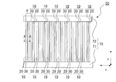
- FIG. 2 is a perspective view schematically showing the configuration of the heat exchanger 50 according to the first embodiment.
- FIG. 3 is a conceptual diagram of the heat exchanger 50 according to the first embodiment as viewed from the side.
- the heat exchanger 50 according to the first embodiment will be described with reference to FIGS. 2 to 3.
- the x-axis direction shown in the figure indicates a first direction, which is a direction in which a plurality of heat transfer members 10 are arranged.
- the y-axis direction indicates a second direction, and in the first embodiment, the central axis C (see FIG. 5) of the plurality of heat transfer members 10 extends.
- the z-axis direction indicates a third direction orthogonal to the first direction and the second direction.
- the heat exchanger 50 has a plurality of headers 70 and a plurality of heat transfer members 10 connected between the plurality of headers 70.
- the header 70 is connected to the ends of the plurality of heat transfer members 10 in the stretching direction.
- the header 70 is formed so as to extend along the first direction, which is the arrangement direction of the plurality of heat transfer members 10.
- the header 70 functions as a fluid distribution mechanism in the heat exchanger 50 that distributes the refrigerant flowing into the heat exchanger 50 to the plurality of heat transfer members 10.
- the header 70 also functions as a fluid merging mechanism in the heat exchanger 50, in which the refrigerant flowing out of the heat exchanger 50 flows out from the plurality of heat transfer members 10 and merges.
- the header 70 has a first header 71 and a second header 72.
- One of the first header 71 and the second header 72 functions as a fluid distribution mechanism, and the other functions as a fluid merging mechanism.
- the first header 71 is connected to one end of each of the plurality of heat transfer members 10 in the stretching direction
- the second header 72 is connected to the other end of each of the plurality of heat transfer members 10 in the stretching direction. .. That is, the first header 71 and the second header 72 are attached to both ends in the y-axis direction, which is the stretching direction of the plurality of heat transfer members 10.
- the header 70 is a plurality of heat transfer members at the ends of the plurality of heat transfer members 10 in the direction (y-axis direction) in which the central axes of the plurality of heat transfer members 10 intersecting in the first direction (x-axis direction) extend. It is connected to the member 10. More specifically, the first header 71 and the second header 72 are attached to both ends of the refrigerant flow section 20 constituting the plurality of heat transfer members 10 in the extending direction. The first header 71 and the second header 72 are connected to the refrigerant flow section 20 of the heat transfer member 10 so that the inside of the header 70 and the inside of the conduit of the refrigerant flow section 20 communicate with each other.
- the header 70 shown in FIGS. 2 and 3 is formed in a rectangular parallelepiped shape so as to form a longitudinal direction along the arrangement direction of the plurality of heat transfer members 10.
- the shape of the header 70 is not limited to the rectangular parallelepiped shape, and may be another shape such as a cylindrical shape.
- the first header 71 is formed with an inlet (not shown) for the refrigerant flowing into the first header 71, or an outlet (not shown) for the refrigerant flowing out of the first header 71.
- the second header 72 is formed with an inlet (not shown) of the refrigerant flowing into the second header 72, or an outlet of the refrigerant flowing out of the second header 72 (not shown). Is formed.
- FIG. 4 is a cross-sectional view of the heat transfer member 10 shown in FIG.
- the heat transfer member 10 exchanges heat between the air flowing along the heat transfer member 10 and the refrigerant flowing in the heat transfer member 10.
- the plurality of heat transfer members 10 are arranged in parallel in the first direction (x-axis direction) at intervals from each other.
- the plurality of heat transfer members 10 are arranged at predetermined intervals P along the longitudinal direction (x-axis direction) of the header 70.
- the heat transfer member 10 has a refrigerant flow section 20 extending in the second direction (y-axis direction).
- the heat transfer member 10 is the first side edge of the refrigerant flow section 20 in the third direction (z-axis direction) that intersects the planes parallel to the first direction (x-axis direction) and the second direction (y-axis direction). It has a portion 20a and a fin portion 30 extending in a third direction (z-axis direction) from the second side edge portion 20b.
- Each of the plurality of refrigerant flow units 20 circulates the refrigerant inside.
- Each of the plurality of refrigerant flow units 20 extends between the first header 71 and the second header 72.
- Each of the plurality of refrigerant flow units 20 is arranged at intervals from each other, and is parallel to the axial direction which is the extending direction of the header 70.
- the plurality of refrigerant flow units 20 are arranged so as to face each other.
- a gap serving as an air flow path is formed between two adjacent refrigerant flow units 20 among the plurality of refrigerant flow units 20.
- the arrangement direction of the plurality of refrigerant flow units 20 which is the first direction is the horizontal direction.
- the arrangement direction of the plurality of refrigerant flow units 20 which is the first direction is not limited to the horizontal direction, and may be a vertical direction or a direction inclined with respect to the vertical direction.
- the stretching direction of the plurality of refrigerant flow units 20 is the vertical direction.
- the stretching direction of the plurality of refrigerant flow units 20 is not limited to the vertical direction, and may be a horizontal direction or a direction inclined with respect to the vertical direction.
- the refrigerant distribution units 20 adjacent to each other among the plurality of refrigerant distribution units 20 are not connected to each other by a heat transfer promoting member.
- the heat transfer promoting member is, for example, a plate fin portion, a corrugated fin portion, or the like.
- the heat exchanger 50 functions as an evaporator of the refrigeration cycle device 100
- the inside of the refrigerant flow unit 20 is formed from one end in the extension direction of the refrigerant flow unit 20, that is, the y-axis direction. Refrigerant flows toward the edge.
- the heat exchanger 50 functions as a condenser of the refrigeration cycle device 100
- the inside of the refrigerant flow unit 20 is directed from the other end to one end in the extension direction of the refrigerant flow unit 20. Refrigerant flows.
- the refrigerant flow section 20 is a flat tube having an oval cross-sectional shape. That is, the outer shape in the cross section perpendicular to the central axis of the refrigerant flow unit 20 is a flat shape.
- the shape of the refrigerant flow unit 20 is not limited, and may be, for example, a flat pipe having a flat cross-sectional shape in one direction such as a rectangular shape.
- the refrigerant flow unit 20 has a pair of first side edge portions 20a and a second side edge portion 20b, and a pair of flat surfaces 11a and flat surfaces 11b. In the cross section shown in FIG.
- the first side edge portion 20a and the second side edge portion 20b are formed so as to be convex outward between the end portion of the flat surface 11a and the end portion of the flat surface 11b.
- the shape is not limited to this.
- the first side edge portion 20a is formed so as to be flat between one end of the flat surface 11a and one end of the flat surface 11b.
- the second side edge portion 20b is formed so as to be flat between the other end portion of the flat surface 11a and the other end portion of the flat surface 11b.
- the first side edge portion 20a is a side edge portion arranged on the upstream side, that is, on the front edge side in the flow of air passing through the heat exchanger 50.
- the second side edge portion 20b is a side edge portion arranged on the downstream side, that is, on the trailing edge side in the flow of air passing through the heat exchanger 50.
- the direction perpendicular to the stretching direction of the refrigerant flow section 20 and along the flat surface 11a and the flat surface 11b may be referred to as the long axis direction of the refrigerant flow section 20.
- the major axis direction of the refrigerant flow section 20 is the left-right direction
- the minor axis direction is the vertical direction.
- the long axis direction of the refrigerant flow unit 20 is the second direction.
- the refrigerant flow section 20 is formed with a plurality of refrigerant passages 22 arranged between the first side edge portion 20a and the second side edge portion 20b along the long axis direction.
- the refrigerant flow unit 20 is a flat perforated pipe in which a plurality of refrigerant passages 22 through which the refrigerant flows are arranged in the air flow direction.
- Each of the plurality of refrigerant passages 22 is formed so as to extend in parallel with the second direction, which is the extension direction of the refrigerant flow section 20.
- Each of the partition walls 23 between the adjacent refrigerant passages 22 is continuous to both ends of the refrigerant flow section 20 in the extending direction.
- the cross-sectional shape and the number of formed refrigerant passages 22 are not limited to the illustrated embodiment, and may be formed in various shapes such as a circular shape or a triangular shape, and may be formed by one or a plurality of formed numbers. Also good.
- the fin portion 30 projects from the end portion in the major axis direction of the refrigerant flow portion 20 in a cross section perpendicular to the second direction.
- the fin portion 30 is a plate-shaped portion that protrudes from the first side edge portion 20a and the second side edge portion 20b and extends in the major axis direction of each of the plurality of refrigerant flow portions 20.
- the fin portion 30 extends in the major axis direction of the refrigerant flow portion 20, but is not limited to this form.
- the fin portion 30 may be formed in a state of being tilted at a predetermined angle in the arrangement direction of the plurality of refrigerant flow portions 20 with respect to the major axis direction.
- the fin portion 30 may be formed by joining with the refrigerant flow section 20, or may be integrally formed with the refrigerant flow section 20. As described above, in the refrigerant distribution units 20 adjacent to each other among the plurality of refrigerant distribution units 20, the refrigerant distribution units 20 are not connected to each other by the heat transfer promoting member. Therefore, the plurality of refrigerant distribution units 20 are not connected to the refrigerant distribution units 20 arranged adjacent to each other via the fin units 30, respectively.
- FIG. 5 is a side view for explaining the positional relationship between the heat exchanger 50 and the vortex generator 80 in the refrigeration cycle device 100 according to the first embodiment.
- FIG. 6 is a schematic view of a cross section perpendicular to the y-axis direction of FIG. FIG. 6 schematically shows that a vortex flow (turbulent flow) is generated on the downstream side of the vortex generator 80.
- the heat exchanger 50 and the vortex generator 80 will be described as being mounted on the outdoor unit 106 of the refrigeration cycle device 100 shown in FIG.
- the heat exchanger 50 and the vortex generator 80 are not limited to those mounted on the outdoor unit 106, and may be mounted on the indoor unit 107.
- the vortex generator 80 allows air supplied from the blower 108 to pass through.
- the laminar air flow before passing through the vortex generator 80 changes to a vortex flow (turbulent flow) after passing through the vortex generator 80. That is, as shown in FIG. 6, a vortex flow (turbulent flow) is generated in the air flow after passing through the vortex generator 80.
- the vortex generator 80 is made of resin or metal.
- the air flow in the heat exchanger 50 will be described. Air is supplied to the heat exchanger 50 by rotating the blower 108. This air will pass through the vortex generator 80 before flowing into the heat exchanger 50. In the vortex generator 80, turbulence occurs in the air flow of the laminar flow, and the air flow of the laminar flow changes to a vortex flow (turbulent flow). Since the vortex (turbulent flow) air flow has a high heat transport and diffusion effect, the heat transfer performance in the heat exchanger 50 can be improved as compared with the laminar flow. That is, the heat exchange in the heat exchanger 50 can be promoted by the vortex effect.
- the vortex generator 80 By installing the vortex generator 80 on the upstream side of the heat exchanger 50, the air flow can be made into a vortex (turbulent flow) on the wind of the heat exchanger 50, and the plurality of heat transfer members 10 of the heat exchanger 50 and the air Heat exchange with and from is promoted, and heat exchange performance is improved.
- the heat exchanger 50 and the vortex generator 80 may be unitized and installed inside the refrigeration cycle device 100, for example, the outdoor unit 106, or may be installed separately as separate bodies.
- the heat exchanger 50 and the vortex generator 80 are arranged at positions as close as possible to each other so that the fin portions 30 of the plurality of heat transfer members 10 do not come into contact with the vortex generator 80.
- the header 71 of the heat exchanger 50 abuts on the vortex generator 80 via the abutting portion 91
- the header 72 abuts on the vortex generator 80 via the abutting portion 92.
- the abutting portion 91 may be formed integrally with the header 71 and the abutting portion 92 may be formed integrally with the header 72, or the abutting portions 91 and 92 may be formed integrally with the vortex generator 80. good.
- each of the plurality of heat transfer members 10 is provided with a refrigerant flow section 20 for circulating a refrigerant inside and a fin section projecting from the refrigerant flow section 20 toward the vortex generator 80. 30a and.
- each of the plurality of heat transfer members 10 includes a fin portion 30b from the refrigerant flow section 20 in a direction opposite to the side where the vortex generator 80 is located.
- the virtual line CL passes within the range of the plate thickness of the fin portion 30a in the first direction. That is, the fin portion 30a overlaps with the virtual line CL.
- the plate thickness of the fin portion 30a in the first direction refers to the width of the fin portion 30a in the x-axis direction shown in FIGS. 7 to 9.
- the virtual line CL coincides with the center of the plate thickness of the fin portion 30a.
- the plurality of ventilation spaces 55 formed between the plurality of heat transfer members 10 shown in FIG. 6 have an even shape. Further, the two adjacent ventilation spaces 55 among the plurality of ventilation spaces 55 have a symmetrical shape with respect to the virtual line CL. As a result, the air flow passing through the ventilation space 55 is stabilized, so that the vortex flow (turbulent flow) attached by the vortex generator 80 can be suppressed from being attenuated in the ventilation space 55. Further, the fin portion 30a has a thinner plate thickness in the first direction than the refrigerant flow portion 20, and the tip 33a is directed to the vortex generator 80. Therefore, when the air from the vortex generator 80 flows into the heat exchanger 50, the area that collides with the heat exchanger 50 is reduced, so that the attenuation of the vortex flow (turbulent flow) can be suppressed.
- FIG. 7 is a cross-sectional view of the heat transfer member 10a which is a modification of the heat transfer member 10 according to the first embodiment.
- the connection portion 12 between the fin portion 30 and the refrigerant flow portion 20 is connected by a smooth curved surface.
- the first side edge portion 20a may also be referred to as a front edge.
- FIG. 8 is a cross-sectional view of the heat transfer member 10b, which is a modified example of the heat transfer member 10 according to the first embodiment.
- the heat transfer member 10a is formed by integrally molding the refrigerant flow portion 20 and the fin portion 30.
- the refrigerant flow portion 20 is sandwiched from both sides of the flat surfaces 21a and 21b by the plate members 31a and 31b forming the fin portion 30. Both ends of the plate members 31a and 31b form fin portions 30a and 30b by joining the facing surfaces to each other. Even with such a configuration, the heat transfer member 10b can obtain the same effect as the heat transfer member 10a.
- the heat transfer member 10b can be formed by joining the plate members 31a and 31b to the refrigerant flow section 20 which is a flat tube, it is compared with the heat transfer member 10 formed by means such as extrusion molding. Therefore, the degree of freedom in the shape of the fin portion 30 can be improved.
- the heat transfer member 10b shown in FIG. 8 sandwiches the refrigerant flow section 20 between two plate members 31a and 31b. For example, only one plate member 31a is joined to the refrigerant flow section 20. You may.
- the fin portions 30a and 30b are formed only of the plate material 31a, but it is preferable that the imaginary line CL is formed so as to overlap the fin portion 30a formed of the plate material 31a.
- FIG. 9 is a cross-sectional view of the heat transfer member 10c, which is a modified example of the heat transfer member 10 according to the first embodiment.
- the heat transfer member 10c includes a tapered surface 32 on the fin portion 30a.
- the tapered surface 32 is formed so that the width of the fin portion 30a in the first direction widens from the tip 33a of the fin portion 30a toward the refrigerant flow portion 20. That is, the fin portion 30a is formed so that the plate thickness increases toward the refrigerant flow portion 20.
- Embodiment 2 The refrigeration cycle apparatus 200 according to the second embodiment will be described.
- the refrigeration cycle device 200 is a modification of the structure of the heat exchanger 50 according to the first embodiment.
- the components having the same functions and functions as those in the first embodiment are designated by the same reference numerals, and the description thereof will be omitted.
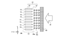
- FIG. 10 is a schematic view illustrating the positional relationship between the heat exchanger 250 and the vortex generator 80 of the refrigeration cycle device 200 according to the second embodiment.
- the refrigeration cycle device 200 has the same circuit configuration as the refrigeration cycle device 100 according to the first embodiment.
- the heat exchanger 250 of the refrigeration cycle device 200 includes two heat exchangers 51 and 52.
- the heat exchange unit 51 arranged on the side where the vortex generator 80 is located is called a first heat exchange unit 51.
- the heat exchange unit 52 located on the downstream side of the air flow passing through the first heat exchange unit 51 is called the second heat exchange unit 52.
- the first heat exchange unit 51 and the second heat exchange unit 52 each have a plurality of headers 70 and a plurality of headers 70 connected between the plurality of headers 70, as in the heat exchanger 50 according to the first embodiment. It has a heat transfer member 10.
- the first heat exchange unit 51 and the second heat exchange unit 52 are arranged in series with respect to the air flow from the vortex generator 80, and each exchanges heat between the refrigerant flowing inside and the air flow. Do.
- the distance between the two adjacent heat transfer members 10 of the plurality of heat transfer members 10 is larger than the distance between the plurality of heat transfer members 10 in the second heat exchange section 52. Is also wide.
- the air flow flowing into the first heat exchange section 51 on the upstream side suppresses the attenuation of the vortex.
- the first heat exchange section 51 suppresses the attenuation of the vortex
- the air flow is attenuated when it reaches the second heat exchange section 52. Even if the vortex is dampened by the first heat exchange unit 51, the second heat exchange unit 52 has a large heat transfer area because the distance between the plurality of heat transfer members 10 is narrow.
- the heat exchanger 250 suppresses the ventilation resistance at the time of frost formation, and also A sufficient heat transfer area can be secured.
- the second heat exchange unit 52 exchanges the first heat.
- the plurality of heat transfer members 10 included in the unit 51 a plurality of heat transfer members 10 located between two adjacent heat transfer members 10 in the first direction are provided.
- a plurality of heat transfer members 10 of the second heat exchange unit 52 are arranged on the downstream side of the plurality of heat transfer members 10 of the first heat exchange unit 51.
- a plurality of heat transfer members 10 of the second heat exchange unit 52 are arranged on the downstream side of each of the plurality of ventilation spaces 255a between the plurality of heat transfer members 10 of the first heat exchange unit 51.
- the second heat exchange unit 52 does not necessarily have to have the heat transfer member 10 arranged on the downstream side of the ventilation space 255a of the first heat exchange unit 51. Further, the heat transfer member 10 of the second heat exchange unit 52 does not necessarily have to be arranged on the downstream side of the heat transfer member 10 of the first heat exchange unit 51.
- Embodiment 3 The refrigeration cycle apparatus 300 according to the third embodiment will be described.
- the refrigeration cycle device 300 is a modification of the structure of the heat exchanger 50 according to the first embodiment.
- the components having the same functions and functions as those in the first embodiment are designated by the same reference numerals, and the description thereof will be omitted.
- FIG. 11 is a schematic view illustrating the positional relationship between the heat exchanger 350 and the vortex generator 80 of the refrigeration cycle device 300 according to the third embodiment.
- the refrigeration cycle device 300 has the same circuit configuration as the refrigeration cycle device 100 according to the first embodiment.
- the heat exchanger 350 of the refrigeration cycle device 300 includes two heat exchange units 51 and 352.
- the heat exchange unit 51 arranged on the side where the vortex generator 80 is located is called a first heat exchange unit 51.
- the heat exchange unit 352 located on the downstream side of the air flow passing through the first heat exchange unit 51 is called the second heat exchange unit 352.
- the plurality of heat transfer members 310 of the second heat exchange unit 352 are arranged in the same manner as the first heat exchange unit 51. However, in the plurality of heat transfer members 310 of the second heat exchange portion 352, the vortex generation portion 40 is formed in the fin portion 30 on the upstream side.
- the vortex generation portion 40 projects from the surface of the fin portion 330 toward the first direction. That is, the fin portion 330 is not in the shape of a flat plate, but has irregularities on its surface.
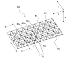
- FIG. 12 is an enlarged view of the heat transfer member 310 of the second heat exchange unit 352 constituting the heat exchanger 350 according to the first embodiment.
- the arrow shown in FIG. 12 represents the airflow FL.
- FIG. 12 is a perspective view of a part of the heat transfer member 310, and the illustration of a part of the heat transfer member 310 is simplified or omitted.
- the configuration of the fin portion 330 will be described in more detail with reference to FIG.
- a plurality of vortex generation portions 40 projecting in the first direction (x-axis direction) are formed on the surface of the fin portion 330.
- the vortex generation portion 40 is formed so as to project in the shape of a quadrangular pyramid.
- the shape of the vortex generation unit 40 is not limited to the shape of a quadrangular pyramid.
- the vortex generation unit 40 may be formed in a hemispherical shape.
- the vortex generation unit 40 is formed so that one surface in the first direction (x-axis direction) is projected and the other surface is recessed.
- the vortex generation unit 40 is formed in parallel in the second direction (y-axis direction) and in parallel in the third direction (z-axis direction).
- the plurality of vortex generation portions 40 are formed so that the ridge line 41 is continuous in the second direction (y-axis direction) and the third direction (z-axis direction).
- the plurality of vortex generation units 40 have a first vortex generation unit 40a projecting from one surface and a second vortex generation unit 40b projecting from the other surface in the first direction (x-axis direction).
- the first vortex generation unit 40a is formed in parallel in the central axis direction (y-axis direction) and in parallel in the third direction (z-axis direction).
- the second vortex generation unit 40b is formed in parallel in the second direction (y-axis direction) and in parallel in the third direction (z-axis direction).
- the plurality of first vortex generation portions 40a are formed so that the ridge lines 41 are continuous in the third direction (z-axis direction).
- the plurality of second vortex generation portions 40b are formed so that the ridge line 41 is continuous in the third direction (z-axis direction).
- the plurality of first vortex generation units 40a and the plurality of second vortex generation units 40b are formed alternately in a direction oblique to a second direction (y-axis direction) and a third direction (z-axis direction).
- FIG. 13 is a cross-sectional view schematically showing a cross section of the fin portion 30 shown in FIG. 12 along the line BB.
- the BB line cross section is a cross section of the fin portion 30 when viewed from the second direction (y-axis direction) when the fin portion 30 is cut along the third direction (z-axis direction).
- FIG. 13 is a cross-sectional view of a part of the heat transfer member 10, and the illustration of a part of the heat transfer member 10 is omitted.
- each of the plurality of first vortex generation portions 40a of the fin portion 30 is formed so as to form an inclined surface 42 having an inclination angle ⁇ with respect to the third direction (z-axis direction). ..
- the inclined surface 42 is a surface on the side located in the protruding direction of the vortex generating portion 40, and is an inclined surface facing upstream with respect to the flow direction of the air flow.
- FIG. 14 is a cross-sectional view schematically showing the CC line cross section of the fin portion 30 shown in FIG.
- the CC line cross section is a cross section of the fin portion 30 when viewed from the third direction (z-axis direction) when the fin portion 30 is cut along the second direction (y-axis direction).
- FIG. 14 is a cross-sectional view of a part of the heat transfer member 10, and the illustration of a part of the heat transfer member 10 is omitted.
- each of the plurality of first vortex generation portions 40a of the fin portion 330 is formed so as to form an inclined surface 43 having an inclination angle ⁇ with respect to the second direction (y-axis direction). ..
- FIG. 15 is an enlarged view of the fin portion 330 of the heat transfer member 310 shown in FIG.
- FIG. 16 is a cross-sectional view schematically showing the configuration of the DD line cross-sectional position of the fin portion 330 shown in FIG.
- FIG. 17 is a cross-sectional view schematically showing the configuration of the EE line cross section of the fin portion 330 shown in FIGS. 15 and 16.
- the arrows shown in FIGS. 15 to 16 represent the airflow FL.
- 16 and 17 are cross-sectional views of a part of the heat transfer member 10, and a part of the heat transfer member 10 is not shown.
- the airflow FL passes between the plurality of heat transfer members 310. As shown in FIG.
- the airflow FL when the airflow FL collides with the first vortex generating portion 40a formed in the fin portion 330, the airflow FL does not flow linearly but flows in a vortex. More specifically, the airflow FL collides with the inclined surface 42 of the first vortex generation unit 40a shown in FIG. 13 to form a vortex rotating in the third direction (z-axis direction) as shown in FIG. .. The airflow FL forming this vortex generates a high-speed flow HL that flows at a high speed toward the recessed portion HA between the first vortex generating portions 40a. Further, the airflow FL collides with the inclined surface 43 of the first vortex generation unit 40a shown in FIG.
- the first vortex generation portion 40a of the fin portion 30 forms a vortex that rotates in the second direction and the third direction with respect to the air flow FL, and agitates the air flow.
- the plurality of vortex generation portions 40 are formed so as to form surfaces having inclination angles with respect to the second direction (y-axis direction) and the third direction (z-axis direction), respectively. ..
- the air flow is agitated by the collision of the air flow with the surfaces inclined in the second direction (y-axis direction) and the third direction (z-axis direction). Therefore, in the heat exchanger 50, air also flows into the surface of the fin portion 30 on the downstream side of the refrigerant flow section 20, and the flow velocity of the air in the vicinity of the surface increases, so that the heat transfer coefficient is improved.
- each of the plurality of first vortex generation portions 40a is formed in a quadrangular pyramid shape, and the ridge line 41 of the first vortex generation portion 40a is formed so as to be continuous in the third direction (z-axis direction). Therefore, in the heat exchanger 50, the airflow FL in which the vortex is formed tends to flow in the third direction (z-axis direction) along the peak-shaped portion formed by the ridgeline 41 as a whole.
- the fin portion 330 has a plurality of vortex generation portions 40 on the surface. Therefore, the surface area of the fin portion 330 can be increased as compared with the case where the vortex generation portion 40 is not formed. Therefore, the heat transfer performance of the second heat exchange unit 352 is improved.
- the second heat exchange unit 352 of the heat exchanger 350 has the second heat exchange unit 352 even if the vortex of the air flow passing through the ventilation space 355a of the first heat exchange unit 51 is attenuated.
- the vortex generating section 40 provided in the fin section 330 on the side where the vortex generating device 80 is arranged can increase the turbulence of the air flow. As a result, the air flow flowing into the second heat exchange section 352 of the heat exchanger 350 becomes a vortex flow (turbulent flow), and the efficiency of heat exchange between the refrigerant and air in the second heat exchange section 352 can be improved.
- the vortex generation unit 40 has a quadrangular pyramid shape, but the vortex generation unit 40 is not limited to this form.
- the vortex generation unit 40 can take other forms such as a polygonal pyramid shape such as a pentagonal pyramid shape and a semi-cylindrical cross section of the protruding portion.
- the plurality of heat transfer members 310 have vortex generation portions 40 formed on both the fin portions 330 on the upstream side and the downstream side of the air flow, but are provided only on the fin portions 330 on the upstream side at least. It is good if it is done.
- the vortex generation section 40 is formed in the fin portion 330 on the upstream side of the second heat exchange section 352, but the vortex generation section 40 is formed in the fin section 30 of the first heat exchange section 51. It may be formed. At this time, in the first heat exchange section 51, the vortex generation section 40 is formed in the fin section 330 projecting toward the second heat exchange section 352.
- the heat exchanger 350 promotes the vortex of the air flow flowing into the second heat exchange unit 352, so that the efficiency of heat exchange is improved. That is, the vortex generation unit 40 may be provided at least between the refrigerant flow unit 20 of the first heat exchange unit 51 and the refrigerant flow unit 20 of the second heat exchange unit 352.
- each of the above embodiments 1 to 3 can be implemented in combination with each other. Further, the configuration shown in the above embodiment is an example, and can be combined with another known technique, and a part of the configuration is omitted or changed without departing from the gist. It is also possible.
Landscapes
- Engineering & Computer Science (AREA)
- Physics & Mathematics (AREA)
- Thermal Sciences (AREA)
- Mechanical Engineering (AREA)
- General Engineering & Computer Science (AREA)
- Geometry (AREA)
- Heat-Exchange Devices With Radiators And Conduit Assemblies (AREA)
- Air Filters, Heat-Exchange Apparatuses, And Housings Of Air-Conditioning Units (AREA)
Priority Applications (4)
| Application Number | Priority Date | Filing Date | Title |
|---|---|---|---|
| JP2021566645A JP7370393B2 (ja) | 2019-12-25 | 2019-12-25 | 熱交換器ユニット及び冷凍サイクル装置 |
| ES19957371T ES2969072T3 (es) | 2019-12-25 | 2019-12-25 | Unidad de intercambiador de calor y dispositivo de ciclo de refrigeración |
| PCT/JP2019/050872 WO2021130910A1 (ja) | 2019-12-25 | 2019-12-25 | 熱交換器ユニット及び冷凍サイクル装置 |
| EP19957371.8A EP4083557B1 (en) | 2019-12-25 | 2019-12-25 | Heat exchanger unit and refrigeration cycle device |
Applications Claiming Priority (1)
| Application Number | Priority Date | Filing Date | Title |
|---|---|---|---|
| PCT/JP2019/050872 WO2021130910A1 (ja) | 2019-12-25 | 2019-12-25 | 熱交換器ユニット及び冷凍サイクル装置 |
Publications (1)
| Publication Number | Publication Date |
|---|---|
| WO2021130910A1 true WO2021130910A1 (ja) | 2021-07-01 |
Family
ID=76573765
Family Applications (1)
| Application Number | Title | Priority Date | Filing Date |
|---|---|---|---|
| PCT/JP2019/050872 Ceased WO2021130910A1 (ja) | 2019-12-25 | 2019-12-25 | 熱交換器ユニット及び冷凍サイクル装置 |
Country Status (4)
| Country | Link |
|---|---|
| EP (1) | EP4083557B1 (https=) |
| JP (1) | JP7370393B2 (https=) |
| ES (1) | ES2969072T3 (https=) |
| WO (1) | WO2021130910A1 (https=) |
Cited By (2)
| Publication number | Priority date | Publication date | Assignee | Title |
|---|---|---|---|---|
| WO2025079135A1 (ja) * | 2023-10-10 | 2025-04-17 | 三菱電機株式会社 | 熱交換器、冷凍サイクル装置および冷凍サイクルシステム |
| US12415815B2 (en) | 2020-01-28 | 2025-09-16 | Globachem Nv | Pyrido[2,3-e]oxazine derivatives as agricultural chemicals |
Citations (8)
| Publication number | Priority date | Publication date | Assignee | Title |
|---|---|---|---|---|
| JPS53162945U (https=) * | 1977-05-30 | 1978-12-20 | ||
| JPS54139356U (https=) * | 1978-03-22 | 1979-09-27 | ||
| JP2011158250A (ja) * | 2011-04-15 | 2011-08-18 | Mitsubishi Electric Corp | 熱交換器及びこの熱交換器を搭載した冷凍冷蔵庫 |
| US20130206376A1 (en) * | 2012-02-14 | 2013-08-15 | The University Of Tokyo | Heat exchanger, refrigeration cycle device equipped with heat exchanger, or heat energy recovery device |
| WO2018066075A1 (ja) * | 2016-10-04 | 2018-04-12 | 三菱電機株式会社 | 冷凍サイクル装置 |
| WO2018066066A1 (ja) | 2016-10-04 | 2018-04-12 | 三菱電機株式会社 | 冷凍サイクル装置 |
| WO2018066067A1 (ja) | 2016-10-04 | 2018-04-12 | 三菱電機株式会社 | 渦発生装置及び冷凍サイクル装置 |
| WO2019167840A1 (ja) * | 2018-03-01 | 2019-09-06 | ダイキン工業株式会社 | 熱交換器 |
Family Cites Families (3)
| Publication number | Priority date | Publication date | Assignee | Title |
|---|---|---|---|---|
| JP2517872Y2 (ja) * | 1989-12-29 | 1996-11-20 | 昭和アルミニウム株式会社 | 熱交換器 |
| JP4026535B2 (ja) * | 2003-04-24 | 2007-12-26 | 株式会社デンソー | 冷却装置 |
| EP3663677A4 (en) * | 2017-08-03 | 2020-07-22 | Mitsubishi Electric Corporation | HEAT EXCHANGER AND COOLING CYCLE DEVICE |
-
2019
- 2019-12-25 WO PCT/JP2019/050872 patent/WO2021130910A1/ja not_active Ceased
- 2019-12-25 ES ES19957371T patent/ES2969072T3/es active Active
- 2019-12-25 EP EP19957371.8A patent/EP4083557B1/en active Active
- 2019-12-25 JP JP2021566645A patent/JP7370393B2/ja active Active
Patent Citations (8)
| Publication number | Priority date | Publication date | Assignee | Title |
|---|---|---|---|---|
| JPS53162945U (https=) * | 1977-05-30 | 1978-12-20 | ||
| JPS54139356U (https=) * | 1978-03-22 | 1979-09-27 | ||
| JP2011158250A (ja) * | 2011-04-15 | 2011-08-18 | Mitsubishi Electric Corp | 熱交換器及びこの熱交換器を搭載した冷凍冷蔵庫 |
| US20130206376A1 (en) * | 2012-02-14 | 2013-08-15 | The University Of Tokyo | Heat exchanger, refrigeration cycle device equipped with heat exchanger, or heat energy recovery device |
| WO2018066075A1 (ja) * | 2016-10-04 | 2018-04-12 | 三菱電機株式会社 | 冷凍サイクル装置 |
| WO2018066066A1 (ja) | 2016-10-04 | 2018-04-12 | 三菱電機株式会社 | 冷凍サイクル装置 |
| WO2018066067A1 (ja) | 2016-10-04 | 2018-04-12 | 三菱電機株式会社 | 渦発生装置及び冷凍サイクル装置 |
| WO2019167840A1 (ja) * | 2018-03-01 | 2019-09-06 | ダイキン工業株式会社 | 熱交換器 |
Non-Patent Citations (1)
| Title |
|---|
| See also references of EP4083557A4 |
Cited By (2)
| Publication number | Priority date | Publication date | Assignee | Title |
|---|---|---|---|---|
| US12415815B2 (en) | 2020-01-28 | 2025-09-16 | Globachem Nv | Pyrido[2,3-e]oxazine derivatives as agricultural chemicals |
| WO2025079135A1 (ja) * | 2023-10-10 | 2025-04-17 | 三菱電機株式会社 | 熱交換器、冷凍サイクル装置および冷凍サイクルシステム |
Also Published As
| Publication number | Publication date |
|---|---|
| JPWO2021130910A1 (https=) | 2021-07-01 |
| EP4083557A1 (en) | 2022-11-02 |
| ES2969072T3 (es) | 2024-05-16 |
| JP7370393B2 (ja) | 2023-10-27 |
| EP4083557B1 (en) | 2023-12-13 |
| EP4083557A4 (en) | 2022-12-14 |
Similar Documents
| Publication | Publication Date | Title |
|---|---|---|
| JP6038302B2 (ja) | 積層型ヘッダー、熱交換器、及び、空気調和装置 | |
| JP6138264B2 (ja) | 積層型ヘッダー、熱交換器、及び、空気調和装置 | |
| JP7278430B2 (ja) | 熱交換器及び冷凍サイクル装置 | |
| JP6890509B2 (ja) | 空気調和機 | |
| JP7370393B2 (ja) | 熱交換器ユニット及び冷凍サイクル装置 | |
| WO2017208493A1 (ja) | 空気調和機 | |
| CN118829842A (zh) | 热交换器以及具备该热交换器的制冷循环装置 | |
| JP7166458B2 (ja) | 熱交換器及び冷凍サイクル装置 | |
| US11549721B2 (en) | Heat exchange unit and air-conditioning apparatus including the same | |
| WO2018100738A1 (ja) | 熱交換器および空気調和装置 | |
| JP7146139B1 (ja) | 熱交換器及び空気調和装置 | |
| JP6685417B2 (ja) | 渦発生装置及び冷凍サイクル装置 | |
| JP7493585B2 (ja) | 熱交換器、熱交換器ユニット及び冷凍サイクル装置 | |
| JP6963098B2 (ja) | 熱交換器、熱交換モジュール、および冷凍サイクル装置 | |
| JP7821412B2 (ja) | 熱交換器及び空気調和機 | |
| KR102206818B1 (ko) | 프로펠러 팬, 실외기 및 냉동 사이클 장치 | |
| JP7654177B1 (ja) | 熱交換器及び空気調和装置 | |
| JP7496832B2 (ja) | 熱交換器、熱交換器ユニット、冷凍サイクル装置、及び熱交換部材の製造方法 | |
| WO2025234040A1 (ja) | 熱交換器およびこの熱交換器を備えた冷凍サイクル装置 | |
| JP7150157B2 (ja) | 熱交換器および冷凍サイクル装置 | |
| JP6925420B2 (ja) | ユニット、及び空気調和機 | |
| JP2024046157A (ja) | 熱交換器、及び室外機 | |
| CN110945300B (zh) | 制冷剂分配器、热交换器及制冷循环装置 | |
| GB2640099A (en) | Refrigerant distributor, heat exchanger, and refrigeration cycle device | |
| JP2016161209A (ja) | 熱交換器 |
Legal Events
| Date | Code | Title | Description |
|---|---|---|---|
| 121 | Ep: the epo has been informed by wipo that ep was designated in this application |
Ref document number: 19957371 Country of ref document: EP Kind code of ref document: A1 |
|
| ENP | Entry into the national phase |
Ref document number: 2021566645 Country of ref document: JP Kind code of ref document: A |
|
| NENP | Non-entry into the national phase |
Ref country code: DE |
|
| ENP | Entry into the national phase |
Ref document number: 2019957371 Country of ref document: EP Effective date: 20220725 |