WO2021130875A1 - スクロール圧縮機、及び、当該スクロール圧縮機を用いる冷凍サイクル装置 - Google Patents
スクロール圧縮機、及び、当該スクロール圧縮機を用いる冷凍サイクル装置 Download PDFInfo
- Publication number
- WO2021130875A1 WO2021130875A1 PCT/JP2019/050720 JP2019050720W WO2021130875A1 WO 2021130875 A1 WO2021130875 A1 WO 2021130875A1 JP 2019050720 W JP2019050720 W JP 2019050720W WO 2021130875 A1 WO2021130875 A1 WO 2021130875A1
- Authority
- WO
- WIPO (PCT)
- Prior art keywords
- scroll
- scroll compressor
- fixed scroll
- case
- flange portion
- Prior art date
- Legal status (The legal status is an assumption and is not a legal conclusion. Google has not performed a legal analysis and makes no representation as to the accuracy of the status listed.)
- Ceased
Links
Images




Classifications
-
- F—MECHANICAL ENGINEERING; LIGHTING; HEATING; WEAPONS; BLASTING
- F04—POSITIVE - DISPLACEMENT MACHINES FOR LIQUIDS; PUMPS FOR LIQUIDS OR ELASTIC FLUIDS
- F04C—ROTARY-PISTON, OR OSCILLATING-PISTON, POSITIVE-DISPLACEMENT MACHINES FOR LIQUIDS; ROTARY-PISTON, OR OSCILLATING-PISTON, POSITIVE-DISPLACEMENT PUMPS
- F04C18/00—Rotary-piston pumps specially adapted for elastic fluids
- F04C18/02—Rotary-piston pumps specially adapted for elastic fluids of arcuate-engagement type, i.e. with circular translatory movement of co-operating members, each member having the same number of teeth or tooth-equivalents
Definitions
- the present invention relates to a scroll compressor and a refrigeration cycle device using the scroll compressor.
- the scroll compressor forms a compression chamber by engaging the spiral wrap provided on the fixed scroll and the spiral wrap provided on the swirl scroll to compress the working fluid (refrigerant).
- the fixed scroll is fixed to the closed container.
- a method of fixing the fixed scroll a method of fastening the fixed scroll and the frame with bolts is widely used.
- the method of fastening using bolts requires time and effort for machining and assembling work because it requires formation of bolt holes and bolt assembly work.
- Patent Document 1 between the closed case divided into the upper case and the lower case and the upper case and the lower case of the closed case.
- a scroll type compressor characterized in that it is provided with a sandwiching portion formed in the above, and a compressor portion housed inside the sealed case and the upper and lower surfaces of the peripheral portion are sandwiched between the sandwiching portions. " It is shown.
- the conventional scroll compressor described in Patent Document 1 has a structure in which a fixed scroll flange portion and a frame flange portion are sandwiched between a case (sealed case) and a lid chamber (upper case).
- a conventional scroll compressor having this structure has a force for sandwiching the flange portion of the fixed scroll and the flange portion of the frame so that the fixed scroll does not separate from the frame during operation (hereinafter referred to as "fixed scroll fastening force"). It is necessary to make sure that remains.
- a case that has been thermally expanded during welding of the case is cooled and contracted (solidified), so that a fixing force (holding force) of a fixed scroll is generated.
- the conventional scroll compressor when fastening the fixed scroll by utilizing the temperature difference between the case, the fixed scroll, and the frame, it is difficult to control the fastening force of the fixed scroll to a desired value.
- the fastening force of the fixed scroll becomes excessive, the contact stress between the parts exceeds the yield point, and as a result, the parts are plastically deformed and the assembly accuracy is lowered.
- the fastening force (holding force) of the fixed scroll would decrease. If the assembly accuracy or the fastening force (holding force) of the fixed scroll is lowered, the sealing property around the fixed scroll may be lowered, which is not preferable.
- a method of fixing the fixed scroll there is a method that does not use the temperature difference between the case, the fixed scroll, and the frame due to welding heat.
- a press load is applied to the lid chamber immediately before welding, the lid chamber is pressed against the case side, and the case and the lid chamber are welded while maintaining the positions of the case and the lid chamber. Conceivable.
- the press load applied at the time of assembly can be freely controlled, and a desired fixed scroll fastening force can be set by the press load.
- the present invention has been made to solve the above-mentioned problems, and is a scroll compressor that suppresses a decrease in the fastening force of a fixed scroll at the time of welding the case and the lid chamber, and the scroll compressor.
- the main purpose is to provide a refrigeration cycle device to be used.
- the present invention is a scroll compressor that supports a fixed scroll having a spiral wrap, a swivel scroll having a spiral wrap that meshes with the wrap of the fixed scroll, and the fixed scroll.
- a frame, a closed container for accommodating the fixed scroll, the swivel scroll, and the frame, and the closed container has a cylindrical case and a lid chamber arranged on the case.
- the fixed scroll and the frame respectively, have a flange portion that is sandwiched between the lid chamber and the case and fixed to the closed container, and the flange portion of the fixed scroll or the frame.
- the flange portion of the above is configured to have a side groove or a stepped portion on the end plate surface side that is in contact with each other on the outermost peripheral portion. Other means will be described later.
- FIG. FIG. 5 is an enlarged view of part A shown in FIG. 1 of the scroll compressor according to the first embodiment. It is a perspective view of a fixed scroll. It is a top view of a fixed scroll. It is explanatory drawing of the elastic deformation (spring) model in the vicinity of a sandwiching portion before welding of a lid chamber and a case. It is explanatory drawing (1) of the deformation and the load change in the vicinity of the sandwiched portion at the time of assembly. It is explanatory drawing (2) of the deformation and the load change in the vicinity of the sandwiched portion at the time of assembly.
- spring elastic deformation
- FIG. 5 is an enlarged view of part A shown in FIG. 1 of the scroll compressor according to the second embodiment. It is explanatory drawing of the modification of the scroll compressor which concerns on Embodiment 2. It is a vertical sectional view of the scroll compressor which concerns on Embodiment 3. It is a perspective view which shows the structure which is deeply cut out. It is explanatory drawing which shows the structure of the air conditioner as an example of a refrigerating cycle apparatus.
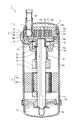
- FIG. 1 is a vertical cross-sectional view of the scroll compressor 1 according to the first embodiment.
- the scroll compressor 1 includes a closed container 2, a compression mechanism unit 3, and an electric motor 4 for driving the swivel scroll 6 of the compression mechanism unit 3.
- the closed container 2 is configured by welding the lid chamber 2b and the bottom chamber 2c vertically at the welded portion 31 to the cylindrical case 2a.
- the lid chamber 2b is provided with a suction pipe 2d.
- a discharge pipe (not shown) is provided on the side surface of the case 2a.
- the compression mechanism portion 3 is arranged in the upper part of the inside of the closed container 2.
- An electric motor 4 is arranged in the lower part of the inside of the closed container 2.
- Lubricating oil 13 is stored in the bottom of the closed container 2.
- the compression mechanism unit 3 has a fixed scroll 5 that is fixedly arranged, a swivel scroll 6 that swivels with respect to the fixed scroll 5, and a frame 9 that is fixed to the closed container 2.
- the fixed scroll 5 has a spiral (spiral) wrap 5c (fixed side wrap).
- the base plate 5d of the fixed scroll 5 has a hollow portion.
- the wrap 5c (fixed side wrap) is formed so as to stand downward from the upper inner wall surface of the base plate 5d inside the hollow portion of the fixed scroll 5.
- the fixed scroll 5 is formed as a flange portion (hereinafter, referred to as “fixed scroll flange portion 5b”) in which a portion in contact with the frame 9 projects in the outer peripheral direction.
- the swivel scroll 6 has a spiral (spiral) lap 6a (swivel side lap) formed so as to mesh with the lap 5c (fixed side lap).
- the lap 6a (fixed side wrap) is formed so as to stand upward on the upper surface of the base plate 6b of the swivel scroll 6.
- the fixed scroll 5 is provided with a side groove 5i on the side surface of the fixed scroll flange portion 5b.
- the frame 9 supports the fixed scroll 5.
- the frame 9 is formed as a flange portion (hereinafter, referred to as “frame flange portion 9b”) in which a portion in contact with the fixed scroll 5 projects in the outer peripheral direction.
- a fixed scroll 5 is arranged on the frame 9.
- the frame 9 is housed inside the case 2a with the fixed scroll 5 arranged on the frame 9. At that time, the frame 9 is arranged at a predetermined position by the frame flange portion 9b coming into contact with the stepped portion 2g (see FIG. 2) provided in the case 2a.
- the lid chamber 2b is arranged on the fixed scroll 5 and the frame 9 with the fixed scroll 5 and the frame 9 housed inside the case 2a.
- the fixed scroll flange portion 5b and the frame flange portion 9b are sandwiched in the axial direction (vertical direction) by the lid chamber 2b and the stepped portion 2g (see FIG. 2) of the case 2a.
- the portion sandwiched between the lid chamber 2b and the case 2a will be referred to as a “sandwiching portion 10”.
- a stepped portion 2g protruding inward is formed on the inner peripheral surface of the case 2a.
- the outer peripheral surface of the sandwiching portion 10 corresponding to the stepped portion 2g has no step and has a flat shape.
- the upper portion of the frame flange portion 9b projects outward, and a step is formed.
- the lower surface of the step of the frame flange portion 9b and the upper surface of the step portion 2g are in contact with each other.
- the fixed scroll 5 and the frame 9 are fixed to the closed container 2 by welding the lid chamber 2b and the case 2a at the welded portion 31 in that state.
- the frame 9 includes a main bearing 9a that rotatably supports the crankshaft 7.
- the eccentric portion 7b of the crankshaft 7 is connected to the lower surface side of the swivel scroll 6.
- An old dam ring 12 is arranged between the lower surface side of the swivel scroll 6 and the frame 9.
- the old dam ring 12 is mounted on a groove formed on the lower surface side of the swivel scroll 6 and a groove formed on the frame 9.
- the old dam ring 12 revolves the swivel scroll 6 in response to the eccentric rotation of the eccentric portion 7b of the crankshaft 7 without rotating the swivel scroll 6.
- the motor 4 includes a stator 4a and a rotor 4b.
- the stator 4a is fastened to the closed container 2 by press fitting, welding, or the like.
- the rotor 4b is rotatably arranged inside the stator 4a.
- a crankshaft 7 is fixed to the rotor 4b.
- the crankshaft 7 includes a main shaft 7a and an eccentric portion 7b.
- the crankshaft 7 is supported by a main bearing 9a and a lower bearing 17 provided on the frame 9.
- the eccentric portion 7b is eccentrically formed integrally with the main shaft 7a of the crankshaft 7, and is fitted to a swivel bearing 6c provided on the back surface of the swivel scroll 6.
- the crankshaft 7 is rotationally driven by the electric motor 4. At that time, the eccentric portion 7b makes an eccentric rotary motion with respect to the spindle 7a to rotate the swivel scroll 6.
- the crankshaft 7 has an internal lubrication passage 7c that guides the lubricating oil 13 to the main bearing 9a, the lower bearing 17, and the swivel bearing 6c.
- the swivel scroll 6 swivels.
- the refrigerant gas is guided from the suction pipe 2d to the fixed scroll 5 via the suction port 5a provided coaxially with the suction pipe 2d.
- the refrigerant gas is further guided to the compression chamber 11 formed by the swivel scroll 6 and the fixed scroll 5.
- the volume of the compression chamber 11 is reduced by moving the swivel scroll 6 toward the center of the scroll.
- the refrigerant gas is compressed.
- the compressed refrigerant gas is discharged from a discharge port 5e provided at substantially the center of the fixed scroll 5 into a space provided above the discharge port 5e.
- the lubricating oil 13 is pumped upward through the oil supply passage 7c by a pressure difference, a pump, or the like, and lubricates the main bearing 9a and the swivel bearing 6c. After that, the lubricating oil 13 flows into the back pressure chamber 16 and further into the compression chamber 11. As a result, the lubricating oil 13 lubricates the inside of the compression chamber 11 while sealing between the lap 5c (fixed side lap) and the lap 6a (swivel side lap). The lubricating oil 13 is mixed with the refrigerant gas inside the compression chamber 11 and discharged from the discharge port 5e into the space provided above the discharge port 5e.
- the scroll compressor 1 has a recess 10c (see FIGS. 2 to 4) in the sandwiching portion 10 in order to suppress a decrease in the fastening force of the fixed scroll 5 during welding between the case 2a and the lid chamber 2b. ) Is formed.
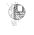
- FIG. 2 is an enlarged view of part A shown in FIG. 1 of the scroll compressor 1.
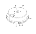
- FIG. 3 is a perspective view of the fixed scroll 5.
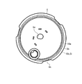
- FIG. 4 is a top view of the fixed scroll 5.
- a recess 10c is provided in the sandwiching portion 10 sandwiched between the lid chamber 2b and the case 2a.
- the recess 10c is provided in at least one of the fixed scroll flange portion 5b and the frame flange portion 9b.
- the recess 10c includes an upper surface portion 10a of the sandwiching portion 10 (that is, an upper surface portion of the fixed scroll flange portion 5b) and a lower surface portion 10b of the sandwiching portion 10 (that is, a lower surface portion of the frame flange portion 9b). It is formed in a shape that leaves. As shown in FIGS. 2 to 4, in the present embodiment, the recess 10c will be described as being provided as the side groove 5i.
- the side groove 5i is a groove provided on the side surface of the fixed scroll flange portion 5b.
- the depth of the side groove 5i (distance from the broken line A11 to the broken line A14) is deeper than the extension (broken line A12) on the end surface of the lid chamber 2b in contact with the fixed scroll flange portion 5b (in the case 2a). (Close to the central axis). Further, the depth of the side groove 5i (distance from the broken line A11 to the broken line A14) is deeper than the extension (broken line A13) of the stepped portion 2g provided in the case 2a in contact with the frame flange portion 9b (central axis of the case 2a). (Close to).
- the bottom surface of the side groove 5i is formed so as to be located inside the inner diameter of the lid chamber 2b and the inner diameter of the case 2a, whichever is smaller. It is desirable that the depth of the side groove 5i is shallower than the side surface of the tubular portion 5g (see FIGS. 2 and 3) of the fixed scroll 5.
- the side groove 5i is provided on the entire circumference of the side surface of the fixed scroll flange portion 5b.
- the fixed scroll flange portion 5b is provided with a notch portion 5k in which the fixed scroll flange portion 5b is partially cut out.
- the cutout portion 5k is different from the side groove 5i in that it is provided so as to penetrate from the upper surface portion to the lower surface portion of the fixed scroll flange portion 5b. That is, the cutout portion 5k is different in that the notched portion 5k is formed in a shape in which the upper surface portion 10a of the sandwiching portion 10 does not remain.
- the outer surface of the side groove 5i has a uniform distance from the center of the fixed scroll 5 over the entire circumference. Therefore, the side groove 5i is shallower in the portion where the notch portion 5k is present than in the portion where the notch portion 5k is not present.
- FIG. 5 is an explanatory view of an elastic deformation (spring) model in the vicinity of the sandwiching portion 10 before the lid chamber 2b and the case 2a are welded.
- FIG. 5 shows an elastic deformation model in the vicinity of the sandwiching portion 10 by replacing the sandwiching portion 10 and its surrounding components with two springs in parallel.
- the spring model MD1 on the left side shows the elastic deformation of the case 2a.
- the spring model MD2 on the right side shows elastic deformation when the lid chamber 2b, the fixed scroll flange portion 5b, and the frame flange portion 9b are combined as one spring.
- the scroll compressor 1 has a major feature in that the rigidity of the spring on the right side is reduced by providing the side groove 5i on the fixed scroll flange portion 5b.
- the two spring models MD1 and MD2 are deformed only one-dimensionally in the vertical direction.
- the lower ends of the two spring models MD1 and MD2 are located at the stepped portion 2g provided in the case 2a. It is assumed that the frame flange portion 9b is always pressed and in contact with the step portion 2g.
- 6 and 7 are explanatory views of the deformation of the sandwiching portion 10 and the change in the load at the time of assembling the scroll compressor 1, respectively.
- FIG. 8 is an explanatory diagram of deformation and load change of the sandwiching portion 10 due to the internal pressure of the closed container 2 of the scroll compressor 1.
- FIG. 6 shows the deformation and load change in the vicinity of the sandwiched portion 10 when the press load P is applied to the lid chamber 2b before welding the lid chamber 2b and the case 2a.
- the two spring models MD1 and MD2 are independent.
- the left spring model MD1 is in a natural length state.
- the spring model MD2 on the right side is in a state of being compressed by the press load P (> 0). Therefore, in the spring model MD2 on the right side, a compressive load Fp as a reaction force (elastic force) with respect to the press load P is generated as an upward force to expand, and the press load P and the compressive load Fp (elastic force) are generated.
- the compressive load of the spring model MD2 on the right side corresponds to the force sandwiching the fixed scroll flange portion 5b and the frame flange portion 9b. Therefore, the compressive load of the spring model MD2 on the right side at this time is the fastening force itself of the fixed scroll 5.
- FIG. 7 shows the deformation and load change in the vicinity of the sandwiched portion 10 at this time.
- the welding point 30 is welded to form the welded portion 31.
- kc and kf correspond to the rigidity coefficient of the spring model MD1 (see FIG. 6) on the left side and the rigidity coefficient of the spring model MD2 (see FIG. 6) on the right side, respectively.
- the scroll compressor 1 is provided with a side groove 5i to reduce the rigidity kf of the spring model MD2 (see FIG. 6) on the right side, so that a press load P which is the same value as the compression load Fp is applied.
- the compressive load Ff that is, the fastening force of the fixed scroll 5 of the spring model MD2 (see FIG. 6) on the right side can be made larger.
- Such a scroll compressor 1 can reduce the amount of decrease in the load lost from the press load P at the time of assembly without being used for the fastening force of the fixed scroll 5. Therefore, the scroll compressor 1 can maintain a sufficient fastening force of the fixed scroll 5 without applying an excessive press load P at the time of assembly.
- FIG. 8 shows the deformation and load change in the vicinity of the sandwiching portion 10 when the internal pressure of the closed container 2 rises during the operation of the scroll compressor 1.
- the gas load Fg acts as an upward force on the spring model MD3.
- the spring model MD1 on the left side (see FIG. 6) and the spring model MD2 on the right side (see FIG. 6) extend with the same displacement ⁇ x2.
- a tensile load ⁇ Fc and a tensile load ⁇ Ff are generated between the spring model MD1 on the left side (see FIG. 6) and the spring model MD2 on the right side (see FIG. 6) as differences from before the gas load Fg acts. To do.
- the scroll compressor 1 can reduce the tensile load ⁇ Ff with respect to the gas load Fg by providing the side groove 5i in the fixed scroll flange portion 5b to reduce the rigidity kf.
- the tensile load ⁇ Ff represents the amount of decrease in the fastening force of the fixed scroll 5. Similar to the states shown in FIGS. 6 and 7, such a scroll compressor 1 can reduce the amount of decrease in the load lost without being used for the fastening force of the fixed scroll 5 from the press load P at the time of assembly. it can. Therefore, the scroll compressor 1 can maintain a sufficient fastening force of the fixed scroll 5 without applying an excessive press load P at the time of assembly.
- the scroll compressor 1 can maintain a sufficiently high fastening force of the fixed scroll 5 during operation while reducing the press load P during assembly.
- the number of parts and the assembly process can be reduced by not using bolts for fastening the fixed scroll 5. Therefore, the scroll compressor 1 can reduce the manufacturing cost.
- the fixed scroll 5 and the frame 9 are fastened with sufficient force, so that the sealing property between the fixed scroll 5 and the frame 9 can be sufficiently ensured. Therefore, the scroll compressor 1 can realize high efficiency.
- the depth of the side groove 5i is larger than that of the broken line A12 or the broken line A13. It is more desirable that it is also deep.
- the depth of the side groove 5i (distance from the broken line A11 to the broken line A14) is deeper than the extension (broken line A12) at the end surface of the lid chamber 2b in contact with the fixed scroll flange portion 5b (close to the central axis of the case 2a). It should be. Further, the depth of the side groove 5i (distance from the broken line A11 to the broken line A14) is deeper than the extension (broken line A13) of the stepped portion 2g provided in the case 2a in contact with the frame flange portion 9b (central axis of the case 2a). It should be (close to). In other words, the bottom surface of the side groove 5i may be formed so as to be located inside the inner diameter of the lid chamber 2b and the inner diameter of the case 2a, whichever is smaller.
- FIG. 9 is a graph showing changes in load and displacement (however, a state before applying internal pressure) from applying a pressing force (pressing load P) to welding and releasing the pressing force.
- the horizontal axis shows the displacement and the vertical axis shows the load.
- the broken line shows the load change of the scroll compressor (not shown) of the comparative example, and the solid line shows the load change of the scroll compressor 1 according to the present embodiment.
- the scroll compressor (not shown) of the comparative example has a configuration in which the side groove 5i as the recess 10c is not formed in the sandwiching portion 10.
- FIG. 9 is a graph showing changes in load and displacement (however, a state before applying internal pressure) from applying a pressing force (pressing load P) to welding and releasing the pressing force.
- the horizontal axis shows the displacement and the vertical axis shows the load.
- the broken line shows the load change of the scroll compressor (not shown) of the comparative example, and the solid line shows the load change of the scroll compressor 1 according
- CAold indicates the casing rigidity (rigidity of the case 2a) of the scroll compressor (not shown) of the comparative example.
- FRold indicates the flange rigidity (rigidity of the fixed scroll flange portion 5b) of the scroll compressor (not shown) of the comparative example.
- DEold indicates the amount of decrease in the fastening force of the fixed scroll 5 of the scroll compressor (not shown) of the comparative example.
- CAnew indicates the casing rigidity (rigidity of the case 2a) of the scroll compressor 1 according to the present embodiment.
- FRnew indicates the flange rigidity (rigidity of the fixed scroll flange portion 5b) of the scroll compressor 1 according to the present embodiment.
- DEnew indicates the amount of decrease in the fastening force of the fixed scroll 5 of the scroll compressor 1 according to the present embodiment.
- the rigidity of the fixed scroll 5 of the scroll compressor 1 according to the present embodiment is lower than the rigidity of the fixed scroll 5 of the scroll compressor (not shown) of the comparative example. Therefore, the amount of decrease in the fastening force DEnew of the fixed scroll 5 of the scroll compressor 1 according to the present embodiment is larger than the amount of decrease in the fastening force DEold of the fixed scroll 5 of the scroll compressor (not shown) of the comparative example. The change in load (slope of the graph) is small.
- the displacement of the casing rigidity CAnew of the scroll compressor 1 according to the present embodiment and the displacement of the casing rigidity CAold of the scroll compressor (not shown) of the comparative example are both zero (natural).
- the displacement of the flange rigidity FRnew of the scroll compressor 1 according to the present embodiment and the displacement of the flange rigidity FRold of the scroll compressor (not shown) of the comparative example are both positions indicated by black dots. Becomes the length of. (3)
- the elastic forces of the casing rigidity CAnew and the flange rigidity FRnew are balanced at the intersection of the two solid lines. The elastic deformation of the case 2a of the scroll compressor 1 and the fixed scroll 5 according to the present embodiment is stopped when the displacement becomes the length represented by this intersection.
- the elastic forces of the casing rigidity CAold and the flange rigidity FRold are balanced at the intersection of the two broken lines.
- the elastic deformation of the case 2a and the fixed scroll 5 of the scroll compressor (not shown) of the comparative example is stopped when the displacement becomes the length represented by this intersection.
- (4) Flange rigidity The load values of FRnew and FRold indicate the fastening force of the fixed scroll 5.
- the flange rigidity FRnew has a smaller decrease in the fastening force of the fixed scroll 5 than the flange rigidity FRold.
- the amount of decrease in the fastening force of the fixed scroll 5 of the scroll compressor 1 according to the present embodiment DEnew is the fastening force of the fixed scroll 5 of the scroll compressor (not shown) of the comparative example.
- the amount of decrease is less than DEold.
- FIG. 10 is a graph showing the change in the minimum fastening force with respect to the assembly press load.
- the horizontal axis shows the assembly press load, and the vertical axis shows the minimum fastening force.
- FIG. 10 shows an example of numerical analysis of the minimum fastening force.
- the "minimum fastening force” means the fastening force of the fixed scroll 5 that remains when the maximum pressure within the default is applied after the scroll compressor 1 is assembled.
- Cold indicates the change in the minimum fastening force with respect to the assembly press load of the scroll compressor (not shown) of the comparative example.
- CONew indicates a change in the minimum fastening force with respect to the assembly press load of the scroll compressor 1 according to the present embodiment.
- the scroll compressor 1 according to the present embodiment can obtain a large minimum fastening force with a small assembly press load as compared with the scroll compressor (not shown) of the comparative example.
- FIGS. 1 to 8 a recess 10c (see FIGS. 2 to 4) of the sandwiching portion 10 is provided on the side surface of the fixed scroll flange portion 5b as a side groove 5i.
- the recess 10c may be provided in the frame flange portion 9b.
- FIG. 11 is an explanatory diagram of a modified example of the scroll compressor 1.
- FIG. 11 shows a configuration in which a side groove 9c as a recess 10c is provided on the side surface of the frame flange portion 9b.
- the side groove 9c is preferably formed to the same depth as the side groove 5i shown in FIG. Further, the side groove 9c is provided on the entire circumference of the side surface of the frame flange portion 9b.
- the scroll compressor 1 having such a configuration suppresses a decrease in the fastening force of the fixed scroll 5 at the time of welding between the case 2a and the lid chamber 2b, as in the case where the side groove 5i is provided in the fixed scroll flange portion 5b. Etc. can be obtained.
- the scroll compressor 1 does not provide the side groove 5i in the fixed scroll flange portion 5b, but the side groove 5i may be provided as in the first embodiment.
- the scroll compressor 1 suppresses a decrease in the fastening force of the fixed scroll 5 during welding between the case 2a and the lid chamber 2b, as in the case where the side groove 5i is provided in the fixed scroll flange portion 5b. The effect of can be obtained.
- the scroll compressor 1 As described above, according to the scroll compressor 1 according to the first embodiment, it is possible to suppress a decrease in the fastening force of the fixed scroll 5 at the time of welding the case 2a and the lid chamber 2b.
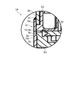
- FIG. 12 is an enlarged view of part A shown in FIG. 1 of the scroll compressor 1A according to the second embodiment.
- the scroll compressor 1A according to the second embodiment has a stepped portion as a recess 10c instead of the side groove 5i as compared with the scroll compressor 1 (see FIG. 2) according to the first embodiment.
- the difference is that 5j is provided on the fixed scroll flange portion 5b.
- the step portion 5j is provided over the entire circumference on the end plate surface 5f of the outermost peripheral portion of the fixed scroll flange portion 5b.
- the inner diameter side surface of the step portion 5j may be formed so as to be located inside the inner diameter of the lid chamber 2b and the inner diameter of the case 2a, whichever is smaller. ..
- the distance from the outermost outer peripheral surface to the inner diameter side surface of the step portion 5j is deeper than any of the broken lines A12 and A13 shown in FIG. 2 (the central axis of the case 2a), similarly to the bottom surface of the side groove 5i shown in FIG. It should be (close to).
- the scroll compressor 1A according to the second embodiment can reduce the rigidity of the fixed scroll flange portion 5b in the same manner as the scroll compressor 1 (see FIG. 2) according to the first embodiment. Moreover, in the scroll compressor 1A according to the second embodiment, when the wrap 5c (fixed side wrap) is formed on the fixed scroll flange portion 5b, at the same time, the end plate surface 5f is cut in the vertical direction to form the step portion 5j. can do. Therefore, the scroll compressor 1A according to the second embodiment can be improved in manufacturability as compared with the scroll compressor 1 (see FIG. 2) according to the first embodiment.
- the scroll compressor 1A according to the second embodiment can maintain a sufficiently high fastening force of the fixed scroll 5 even during operation while reducing the press load P at the time of assembly. Further, the scroll compressor 1A according to the second embodiment can achieve both cost reduction by reducing the number of parts and the assembly process and high efficiency by improving the sealing property.
- FIG. 13 is an explanatory diagram of a modified example of the scroll compressor 1A.
- FIG. 13 shows a configuration in which a step portion 9e as a recess 10c is provided on the side surface of the frame flange portion 9b.
- the step portion 9e is provided over the entire circumference on the end plate surface 9d of the outermost peripheral portion of the frame flange portion 9b.
- the configuration shown in FIG. 13 can obtain the same effect as the configuration shown in FIG.
- the scroll compressor 1A may be configured to have both a step portion 5j and a step portion 9e.
- FIG. 14 is a vertical cross-sectional view of the scroll compressor 1B according to the third embodiment.
- the scroll compressors 1 and 1A (see FIG. 1) according to the above-described first and second embodiments have a shape in which the lower end portion of the lid chamber 2b enters the inside of the case 2a. That is, the scroll compressors 1 and 1A (see FIG. 1) according to the first and second embodiments described above have an "inner cover type" configuration.
- the scroll compressor 1B according to the third embodiment has a shape in which the lower end portion of the lid chamber 2b is placed on the upper end portion of the case 2a. That is, the scroll compressor 1B according to the third embodiment has a "covering type" configuration.
- the scroll compressor 1B according to the third embodiment is different from the scroll compressors 1 and 1A (see FIG. 1) according to the first and second embodiments.
- the frame flange portion 9b and the fixed scroll flange portion 5b are placed on the upper end surface of the case 2a in the sandwiching portion 10. Then, the enlarged portion 2h enlarged in the radial direction of the lid chamber 2b is placed on the fixed scroll flange portion 5b. The enlarged portion 2h of the lid chamber 2b sandwiches the sandwiching portion 10 (fixed scroll flange portion 5b and frame flange portion 9b) with the upper end portion of the case 2a, and fixes the sandwiching portion 10 to the closed container 2.
- the scroll compressor 1B according to the third embodiment has a configuration in which the inner diameter of the lid chamber 2b is larger than the outer diameter of the case 2a, and the lid chamber 2b covers the case 2a. ..
- the depth of the side groove 5i provided on the side surface of the fixed scroll flange portion 5b is deeper than the inner peripheral surface of the case 2a. Further, the depth of the side groove 5i is deeper than the contact point between the lid chamber 2b and the fixed scroll flange portion 5b.
- the side groove 5i as the recess 10c is fixed to the scroll flange portion 5b, similarly to the scroll compressor 1 (see FIG. 1) according to the first embodiment. It is provided in.
- the side groove 9c (see FIG. 11) as the recess 10c is a frame flange, as in the modification of the scroll compressor 1 according to the first embodiment (see FIG. 11). It may be provided in the part 9b.
- the scroll compressor 1B according to the third embodiment may have a configuration having both a side groove 5i and a side groove 9c (see FIG. 11) as the recess 10c.
- the scroll compressor 1B according to the third embodiment has a stepped portion 5j (see FIG. 12) as a recess 10c instead of the side groove 5i, similarly to the scroll compressor 1A (see FIG. 12) according to the second embodiment. May be provided on the fixed scroll flange portion 5b.
- the step portion 9e as the recess 10c instead of the side groove 5i, may be provided on the frame flange portion 9b.
- the scroll compressor 1B according to the third embodiment may have a configuration having both a step portion 5j (see FIG. 12) and a step portion 9e (see FIG. 13) as the recess 10c.
- the shape of the lid chamber 2b of the scroll compressor 1B according to the third embodiment is slightly more complicated than that of the scroll compressors 1 and 1A (see FIG. 1) according to the first and second embodiments.
- the scroll compressors 1 and 1A (see FIG. 1) according to the first and second embodiments have a configuration in which the frame 9 is supported by a step portion 2g provided inside the case 2a.
- the scroll compressor 1B according to the third embodiment has a configuration in which the frame 9 is supported by the entire upper end surface of the case 2a.
- Such a scroll compressor 1B according to the third embodiment can have a larger press load P at the time of assembly than the scroll compressors 1 and 1A (see FIG. 1) according to the first and second embodiments.
- the scroll compressor 1B according to the third embodiment can increase the fastening force of the fixed scroll 5 during operation as compared with the scroll compressors 1 and 1A (see FIG. 1) according to the first and second embodiments. ..
- the scroll compressor 1B according to the third embodiment can further improve the sealing property between the fixed scroll 5 and the frame 9, and can realize high efficiency.
- the present invention is not necessarily limited to those including all the components described above.
- the present invention can add other components to a certain component, or change some components to other components.
- the present invention can also delete some components.
- FIG. 15 is a perspective view showing a configuration in which the notch portion 5k is deeply notched.
- the side groove 5i is divided by deeply notching the notch portion 5k. That is, although the side groove 5i is formed on the entire circumference of the outer peripheral surface of the fixed scroll 5, it is divided by the notch 5k.
- the scroll compressor 1 can be used as a compressor of a refrigeration cycle apparatus (see FIG. 16) including a refrigeration cycle (heat pump cycle) including a compressor, a condenser, and an evaporator.
- the refrigerating cycle device includes an air conditioner, a heat pump water heater, a refrigerator, and the like.
- the scroll compressor 1 can also be used as a gas compressor for compressing air and other gases.
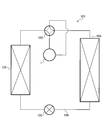
- FIG. 16 is an explanatory diagram showing the configuration of an air conditioner 101 as an example of a refrigeration cycle device.
- the air conditioner 101 includes a scroll compressor 1, a four-way valve 102, an air-conditioning throttle device 103 such as an expander, an indoor heat exchanger 104, and an outdoor heat exchanger 105. These are connected in a ring shape by a predetermined pipe 106.
- the air conditioner 101 can perform cooling operation and heating operation by switching the four-way valve 102.
- the air conditioner 101 uses the indoor heat exchanger 104 as an evaporator and the outdoor heat exchanger 105 as a condenser during the cooling operation.
- the air conditioner 101 uses the indoor heat exchanger 104 as a condenser and the outdoor heat exchanger 105 as an evaporator during the heating operation.
- the air-conditioning throttle device 103 is used for expanding the refrigerant.
Landscapes
- Engineering & Computer Science (AREA)
- Mechanical Engineering (AREA)
- General Engineering & Computer Science (AREA)
- Rotary Pumps (AREA)
- Compressor (AREA)
- Applications Or Details Of Rotary Compressors (AREA)
Priority Applications (3)
| Application Number | Priority Date | Filing Date | Title |
|---|---|---|---|
| PCT/JP2019/050720 WO2021130875A1 (ja) | 2019-12-24 | 2019-12-24 | スクロール圧縮機、及び、当該スクロール圧縮機を用いる冷凍サイクル装置 |
| JP2021566618A JP7304432B2 (ja) | 2019-12-24 | 2019-12-24 | スクロール圧縮機、及び、当該スクロール圧縮機を用いる冷凍サイクル装置 |
| CN201980103310.7A CN114901948B (zh) | 2019-12-24 | 2019-12-24 | 涡旋压缩机及使用该涡旋压缩机的制冷循环装置 |
Applications Claiming Priority (1)
| Application Number | Priority Date | Filing Date | Title |
|---|---|---|---|
| PCT/JP2019/050720 WO2021130875A1 (ja) | 2019-12-24 | 2019-12-24 | スクロール圧縮機、及び、当該スクロール圧縮機を用いる冷凍サイクル装置 |
Publications (1)
| Publication Number | Publication Date |
|---|---|
| WO2021130875A1 true WO2021130875A1 (ja) | 2021-07-01 |
Family
ID=76575823
Family Applications (1)
| Application Number | Title | Priority Date | Filing Date |
|---|---|---|---|
| PCT/JP2019/050720 Ceased WO2021130875A1 (ja) | 2019-12-24 | 2019-12-24 | スクロール圧縮機、及び、当該スクロール圧縮機を用いる冷凍サイクル装置 |
Country Status (3)
| Country | Link |
|---|---|
| JP (1) | JP7304432B2 (https=) |
| CN (1) | CN114901948B (https=) |
| WO (1) | WO2021130875A1 (https=) |
Cited By (1)
| Publication number | Priority date | Publication date | Assignee | Title |
|---|---|---|---|---|
| WO2024105950A1 (ja) * | 2022-11-15 | 2024-05-23 | 三菱電機株式会社 | スクロール圧縮機 |
Citations (1)
| Publication number | Priority date | Publication date | Assignee | Title |
|---|---|---|---|---|
| JP2003056463A (ja) * | 2001-08-10 | 2003-02-26 | Toyota Industries Corp | 電動コンプレッサ |
Family Cites Families (5)
| Publication number | Priority date | Publication date | Assignee | Title |
|---|---|---|---|---|
| JP2009162102A (ja) * | 2008-01-07 | 2009-07-23 | Hitachi Appliances Inc | 密閉形スクロール圧縮機 |
| JP4951572B2 (ja) * | 2008-03-31 | 2012-06-13 | 日立アプライアンス株式会社 | スクロール圧縮機 |
| JP5433603B2 (ja) * | 2011-02-25 | 2014-03-05 | 日立アプライアンス株式会社 | スクロール圧縮機 |
| CN105074218B (zh) * | 2013-03-29 | 2017-10-13 | 江森自控日立空调技术(香港)有限公司 | 涡旋压缩机 |
| JP6765508B2 (ja) * | 2017-03-29 | 2020-10-07 | 三菱電機株式会社 | スクロール圧縮機、およびスクロール圧縮機の製造方法 |
-
2019
- 2019-12-24 CN CN201980103310.7A patent/CN114901948B/zh active Active
- 2019-12-24 WO PCT/JP2019/050720 patent/WO2021130875A1/ja not_active Ceased
- 2019-12-24 JP JP2021566618A patent/JP7304432B2/ja active Active
Patent Citations (1)
| Publication number | Priority date | Publication date | Assignee | Title |
|---|---|---|---|---|
| JP2003056463A (ja) * | 2001-08-10 | 2003-02-26 | Toyota Industries Corp | 電動コンプレッサ |
Cited By (4)
| Publication number | Priority date | Publication date | Assignee | Title |
|---|---|---|---|---|
| WO2024105950A1 (ja) * | 2022-11-15 | 2024-05-23 | 三菱電機株式会社 | スクロール圧縮機 |
| JPWO2024105950A1 (https=) * | 2022-11-15 | 2024-05-23 | ||
| GB2638576A (en) * | 2022-11-15 | 2025-08-27 | Mitsubishi Electric Corp | Scroll compressor |
| JP7796897B2 (ja) | 2022-11-15 | 2026-01-09 | 三菱電機株式会社 | スクロール圧縮機 |
Also Published As
| Publication number | Publication date |
|---|---|
| JP7304432B2 (ja) | 2023-07-06 |
| CN114901948B (zh) | 2023-05-12 |
| CN114901948A (zh) | 2022-08-12 |
| JPWO2021130875A1 (https=) | 2021-07-01 |
Similar Documents
| Publication | Publication Date | Title |
|---|---|---|
| US4545747A (en) | Scroll-type compressor | |
| US5622487A (en) | Scroll compressor having a separate stationary wrap element secured to a frame | |
| EP2093374A1 (en) | Fluid machine and refrigeration cycle device | |
| JP4969648B2 (ja) | 膨張機一体型圧縮機およびそれを備えた冷凍サイクル装置 | |
| US8127567B2 (en) | Shaft coupling and arrangement for fluid machine and refrigeration cycle apparatus | |
| CN104271958A (zh) | 具有多个直径的压缩机外壳 | |
| US4995789A (en) | Enclosed type electric compressor | |
| JP2017025762A (ja) | 圧縮機 | |
| WO2021130875A1 (ja) | スクロール圧縮機、及び、当該スクロール圧縮機を用いる冷凍サイクル装置 | |
| JP3590432B2 (ja) | スクロール式機械 | |
| JP2009270529A (ja) | 容積形流体機械 | |
| JPH06264881A (ja) | ロータリ圧縮機 | |
| JP2009174407A (ja) | スクロール圧縮機 | |
| JP6743407B2 (ja) | スクロール圧縮機及びそれを備えた空気調和装置 | |
| JP2010019176A (ja) | スクロール圧縮機 | |
| JP6271217B2 (ja) | スクロール圧縮機 | |
| JP7398577B2 (ja) | スクロール圧縮機及び冷凍サイクル装置 | |
| CN101324233A (zh) | 涡旋式压缩机及其运行方式 | |
| JP2008157109A (ja) | スクロール圧縮機および冷凍サイクル | |
| JP7719400B1 (ja) | 圧縮機、冷凍装置、及び圧縮機の組立方法 | |
| JP7686501B2 (ja) | 圧縮機、および空気調和機 | |
| JP2502690B2 (ja) | 密閉形電動圧縮機 | |
| JP2009002223A (ja) | スクロール圧縮機 | |
| CN115726967A (zh) | 压缩机以及空调机 | |
| JP2007270818A (ja) | 流体機械及び冷凍サイクル装置 |
Legal Events
| Date | Code | Title | Description |
|---|---|---|---|
| 121 | Ep: the epo has been informed by wipo that ep was designated in this application |
Ref document number: 19957618 Country of ref document: EP Kind code of ref document: A1 |
|
| ENP | Entry into the national phase |
Ref document number: 2021566618 Country of ref document: JP Kind code of ref document: A |
|
| NENP | Non-entry into the national phase |
Ref country code: DE |
|
| 122 | Ep: pct application non-entry in european phase |
Ref document number: 19957618 Country of ref document: EP Kind code of ref document: A1 |