WO2021130821A1 - 羽根車、多翼送風機、及び空気調和装置 - Google Patents
羽根車、多翼送風機、及び空気調和装置 Download PDFInfo
- Publication number
- WO2021130821A1 WO2021130821A1 PCT/JP2019/050392 JP2019050392W WO2021130821A1 WO 2021130821 A1 WO2021130821 A1 WO 2021130821A1 JP 2019050392 W JP2019050392 W JP 2019050392W WO 2021130821 A1 WO2021130821 A1 WO 2021130821A1
- Authority
- WO
- WIPO (PCT)
- Prior art keywords
- blade
- blades
- impeller
- blower
- region
- Prior art date
- Legal status (The legal status is an assumption and is not a legal conclusion. Google has not performed a legal analysis and makes no representation as to the accuracy of the status listed.)
- Ceased
Links
Images

















Classifications
-
- F—MECHANICAL ENGINEERING; LIGHTING; HEATING; WEAPONS; BLASTING
- F04—POSITIVE - DISPLACEMENT MACHINES FOR LIQUIDS; PUMPS FOR LIQUIDS OR ELASTIC FLUIDS
- F04D—NON-POSITIVE-DISPLACEMENT PUMPS
- F04D29/00—Details, component parts, or accessories
- F04D29/26—Rotors specially for elastic fluids
- F04D29/28—Rotors specially for elastic fluids for centrifugal or helico-centrifugal pumps for radial-flow or helico-centrifugal pumps
- F04D29/281—Rotors specially for elastic fluids for centrifugal or helico-centrifugal pumps for radial-flow or helico-centrifugal pumps for fans or blowers
-
- F—MECHANICAL ENGINEERING; LIGHTING; HEATING; WEAPONS; BLASTING
- F04—POSITIVE - DISPLACEMENT MACHINES FOR LIQUIDS; PUMPS FOR LIQUIDS OR ELASTIC FLUIDS
- F04D—NON-POSITIVE-DISPLACEMENT PUMPS
- F04D17/00—Radial-flow pumps, e.g. centrifugal pumps; Helico-centrifugal pumps
- F04D17/08—Centrifugal pumps
- F04D17/16—Centrifugal pumps for displacing without appreciable compression
- F04D17/162—Double suction pumps
-
- F—MECHANICAL ENGINEERING; LIGHTING; HEATING; WEAPONS; BLASTING
- F04—POSITIVE - DISPLACEMENT MACHINES FOR LIQUIDS; PUMPS FOR LIQUIDS OR ELASTIC FLUIDS
- F04D—NON-POSITIVE-DISPLACEMENT PUMPS
- F04D29/00—Details, component parts, or accessories
- F04D29/26—Rotors specially for elastic fluids
- F04D29/28—Rotors specially for elastic fluids for centrifugal or helico-centrifugal pumps for radial-flow or helico-centrifugal pumps
- F04D29/281—Rotors specially for elastic fluids for centrifugal or helico-centrifugal pumps for radial-flow or helico-centrifugal pumps for fans or blowers
- F04D29/282—Rotors specially for elastic fluids for centrifugal or helico-centrifugal pumps for radial-flow or helico-centrifugal pumps for fans or blowers the leading edge of each vane being substantially parallel to the rotation axis
-
- F—MECHANICAL ENGINEERING; LIGHTING; HEATING; WEAPONS; BLASTING
- F04—POSITIVE - DISPLACEMENT MACHINES FOR LIQUIDS; PUMPS FOR LIQUIDS OR ELASTIC FLUIDS
- F04D—NON-POSITIVE-DISPLACEMENT PUMPS
- F04D29/00—Details, component parts, or accessories
- F04D29/26—Rotors specially for elastic fluids
- F04D29/28—Rotors specially for elastic fluids for centrifugal or helico-centrifugal pumps for radial-flow or helico-centrifugal pumps
- F04D29/288—Part of the wheel having an ejecting effect, e.g. being bladeless diffuser
-
- F—MECHANICAL ENGINEERING; LIGHTING; HEATING; WEAPONS; BLASTING
- F04—POSITIVE - DISPLACEMENT MACHINES FOR LIQUIDS; PUMPS FOR LIQUIDS OR ELASTIC FLUIDS
- F04D—NON-POSITIVE-DISPLACEMENT PUMPS
- F04D29/00—Details, component parts, or accessories
- F04D29/26—Rotors specially for elastic fluids
- F04D29/28—Rotors specially for elastic fluids for centrifugal or helico-centrifugal pumps for radial-flow or helico-centrifugal pumps
- F04D29/30—Vanes
-
- F—MECHANICAL ENGINEERING; LIGHTING; HEATING; WEAPONS; BLASTING
- F04—POSITIVE - DISPLACEMENT MACHINES FOR LIQUIDS; PUMPS FOR LIQUIDS OR ELASTIC FLUIDS
- F04D—NON-POSITIVE-DISPLACEMENT PUMPS
- F04D29/00—Details, component parts, or accessories
- F04D29/40—Casings; Connections of working fluid
- F04D29/42—Casings; Connections of working fluid for radial or helico-centrifugal pumps
- F04D29/4206—Casings; Connections of working fluid for radial or helico-centrifugal pumps especially adapted for elastic fluid pumps
- F04D29/4213—Casings; Connections of working fluid for radial or helico-centrifugal pumps especially adapted for elastic fluid pumps suction ports
-
- F—MECHANICAL ENGINEERING; LIGHTING; HEATING; WEAPONS; BLASTING
- F04—POSITIVE - DISPLACEMENT MACHINES FOR LIQUIDS; PUMPS FOR LIQUIDS OR ELASTIC FLUIDS
- F04D—NON-POSITIVE-DISPLACEMENT PUMPS
- F04D29/00—Details, component parts, or accessories
- F04D29/66—Combating cavitation, whirls, noise, vibration or the like; Balancing
- F04D29/661—Combating cavitation, whirls, noise, vibration or the like; Balancing especially adapted for elastic fluid pumps
- F04D29/666—Combating cavitation, whirls, noise, vibration or the like; Balancing especially adapted for elastic fluid pumps by means of rotor construction or layout, e.g. unequal distribution of blades or vanes
-
- F—MECHANICAL ENGINEERING; LIGHTING; HEATING; WEAPONS; BLASTING
- F05—INDEXING SCHEMES RELATING TO ENGINES OR PUMPS IN VARIOUS SUBCLASSES OF CLASSES F01-F04
- F05D—INDEXING SCHEME FOR ASPECTS RELATING TO NON-POSITIVE-DISPLACEMENT MACHINES OR ENGINES, GAS-TURBINES OR JET-PROPULSION PLANTS
- F05D2240/00—Components
- F05D2240/20—Rotors
- F05D2240/30—Characteristics of rotor blades, i.e. of any element transforming dynamic fluid energy to or from rotational energy and being attached to a rotor
- F05D2240/301—Cross-sectional characteristics
-
- F—MECHANICAL ENGINEERING; LIGHTING; HEATING; WEAPONS; BLASTING
- F05—INDEXING SCHEMES RELATING TO ENGINES OR PUMPS IN VARIOUS SUBCLASSES OF CLASSES F01-F04
- F05D—INDEXING SCHEME FOR ASPECTS RELATING TO NON-POSITIVE-DISPLACEMENT MACHINES OR ENGINES, GAS-TURBINES OR JET-PROPULSION PLANTS
- F05D2240/00—Components
- F05D2240/20—Rotors
- F05D2240/30—Characteristics of rotor blades, i.e. of any element transforming dynamic fluid energy to or from rotational energy and being attached to a rotor
- F05D2240/303—Characteristics of rotor blades, i.e. of any element transforming dynamic fluid energy to or from rotational energy and being attached to a rotor related to the leading edge of a rotor blade
-
- F—MECHANICAL ENGINEERING; LIGHTING; HEATING; WEAPONS; BLASTING
- F05—INDEXING SCHEMES RELATING TO ENGINES OR PUMPS IN VARIOUS SUBCLASSES OF CLASSES F01-F04
- F05D—INDEXING SCHEME FOR ASPECTS RELATING TO NON-POSITIVE-DISPLACEMENT MACHINES OR ENGINES, GAS-TURBINES OR JET-PROPULSION PLANTS
- F05D2240/00—Components
- F05D2240/20—Rotors
- F05D2240/30—Characteristics of rotor blades, i.e. of any element transforming dynamic fluid energy to or from rotational energy and being attached to a rotor
- F05D2240/304—Characteristics of rotor blades, i.e. of any element transforming dynamic fluid energy to or from rotational energy and being attached to a rotor related to the trailing edge of a rotor blade
-
- F—MECHANICAL ENGINEERING; LIGHTING; HEATING; WEAPONS; BLASTING
- F24—HEATING; RANGES; VENTILATING
- F24F—AIR-CONDITIONING; AIR-HUMIDIFICATION; VENTILATION; USE OF AIR CURRENTS FOR SCREENING
- F24F1/00—Room units for air-conditioning, e.g. separate or self-contained units or units receiving primary air from a central station
- F24F1/0007—Indoor units, e.g. fan coil units
- F24F1/0043—Indoor units, e.g. fan coil units characterised by mounting arrangements
- F24F1/0047—Indoor units, e.g. fan coil units characterised by mounting arrangements mounted in the ceiling or at the ceiling
-
- F—MECHANICAL ENGINEERING; LIGHTING; HEATING; WEAPONS; BLASTING
- F24—HEATING; RANGES; VENTILATING
- F24F—AIR-CONDITIONING; AIR-HUMIDIFICATION; VENTILATION; USE OF AIR CURRENTS FOR SCREENING
- F24F1/00—Room units for air-conditioning, e.g. separate or self-contained units or units receiving primary air from a central station
- F24F1/02—Self-contained room units for air-conditioning, i.e. with all apparatus for treatment installed in a common casing
- F24F1/03—Self-contained room units for air-conditioning, i.e. with all apparatus for treatment installed in a common casing characterised by mounting arrangements
- F24F1/0317—Self-contained room units for air-conditioning, i.e. with all apparatus for treatment installed in a common casing characterised by mounting arrangements suspended from the ceiling
-
- F—MECHANICAL ENGINEERING; LIGHTING; HEATING; WEAPONS; BLASTING
- F24—HEATING; RANGES; VENTILATING
- F24F—AIR-CONDITIONING; AIR-HUMIDIFICATION; VENTILATION; USE OF AIR CURRENTS FOR SCREENING
- F24F2221/00—Details or features not otherwise provided for
- F24F2221/14—Details or features not otherwise provided for mounted on the ceiling
Definitions
- the present invention relates to an impeller, a multi-blade blower equipped with the impeller, and an air conditioner equipped with the multi-blade blower.
- a multi-blade blower has a spiral-shaped scroll casing and an impeller housed inside the scroll casing and rotating around an axis (see, for example, Patent Document 1).
- the impeller constituting the multi-blade blower of Patent Document 1 has a disk-shaped main plate, an annular side plate, and blades arranged radially.
- the blades constituting this impeller are configured such that the main blades and the intermediate blades are arranged alternately, and the inner diameters of the main blades and the intermediate blades increase from the main plate to the side plates.
- the blades constituting this impeller are sirocco blades (forward blades) having an outlet angle of 100 ° or more, and a turbo blade (rear blade) inducer portion is provided on the inner peripheral side of the blades.
- the ratio of the inner diameter of the main blade to the outer diameter of the blade on the main plate side is 0.7 or less.
- the multi-blade blower of Patent Document 1 has a single suction type impeller that sucks air into the impeller from one side in the axial direction of the impeller.
- a double suction type impeller that sucks air into the impeller from both sides in the axial direction of the impeller
- the flow of suction air differs between one suction side and the other suction side depending on the usage pattern or environment.
- a motor is arranged in the vicinity of one suction side, the presence of the motor substantially reduces the air suction area, resulting in loss.
- the present invention is for solving the above-mentioned problems, and is a double-suction type impeller, in which the flow of suction air is divided into one suction side and the other suction side depending on the usage mode or usage environment. It is an object of the present invention to provide an impeller in which the suction loss of the impeller is suppressed even if the impeller is different, a multi-blade blower equipped with the impeller, and an air conditioner equipped with the multi-blade blower.
- a plurality of impellers according to the present invention are connected to a main plate that is rotationally driven, an annular side plate that is arranged so as to face the main plate, and the main plate and the side plates, and are arranged in the circumferential direction about the rotation axis of the main plate.
- Each of the plurality of blades has an inner peripheral end located on the rotation axis side in the radial direction centered on the rotation axis, and an outer peripheral end located on the outer peripheral side of the inner peripheral end in the radial direction.
- a plurality of sirocco blades including the outer peripheral end and forming an outlet angle larger than 90 degrees and a turbo blade including the inner peripheral end and forming a rearward blade.
- the blade has a first blade portion formed on one plate surface side of the main plate and a second blade portion formed on the other plate surface side of the main plate, and has a plurality of blades in the circumferential direction.
- the distance between two blades adjacent to each other is defined as the distance between the blades
- the distance between the blades of the first blade is defined as the distance between the first blades
- the distance between the blades of the second blade is defined as the distance between the second blades. It has a region in which one wing is formed larger than the second wing.
- the multi-blade blower according to the present invention includes an impeller having the above configuration, a peripheral wall formed in a spiral shape, and a side wall having a bell mouth forming a suction port communicating with a space formed by a main plate and a plurality of blades. , And a scroll casing for accommodating impellers.
- the air conditioner according to the present invention is provided with a multi-blade blower having the above configuration.
- a plurality of blades have a first wing portion formed on one plate surface side of the main plate and a second wing portion formed on the other plate surface side of the main plate. It has a region in which the space between the first blades of one blade portion is larger than that between the second blades of the second blade portion. Therefore, even if the impeller of both suction types has different suction air flow between one suction side and the other suction side depending on the usage mode or environment, the second blade is on the side where the suction air flow is small.
- the first blade portion in which the distance between the blades is wider than that of the portion, the flow rate of the suction air on the first blade portion side can be increased. As a result, the impeller can suppress the suction loss.
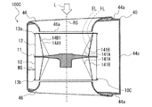
- FIG. 5 is an external view schematically showing a configuration in which a multi-blade blower according to the first embodiment is viewed in parallel with a rotation axis. It is sectional drawing which shows typically the AA line cross section of the multi-blade blower of FIG. It is a perspective view of the impeller which constitutes the multi-blade blower which concerns on Embodiment 1.
- FIG. It is a side view of the impeller of FIG. It is a schematic diagram which shows the vane in the CC line cross section of the impeller of FIG. It is a schematic diagram which shows the vane in the DD line cross section of the impeller of FIG.
- FIG. It is a schematic diagram which shows the cross section of the impeller which concerns on the modification of the impeller shown in FIG. It is a conceptual diagram explaining the impeller connected to the motor in the multi-blade blower which concerns on Embodiment 1.
- FIG. It is a schematic diagram which shows the blade in the CC line cross section of the 1st wing part of FIG. It is a schematic diagram which shows the blade in the CC line cross section of the 2nd wing part of FIG. It is a schematic diagram which shows the blade in the DD line cross section of the 1st wing part of FIG. It is a schematic diagram which shows the blade in the DD line cross section of the 2nd wing part of FIG.
- FIG. 6 is a schematic view showing a relationship between a blade and a bell mouth when viewed in parallel with a rotation axis in the second cross section of the impeller of FIG. 14. It is a schematic diagram which shows the relationship between an impeller and a bell mouth in the AA line cross section of the multi-blade blower of FIG. It is a schematic diagram which shows the relationship between a blade and a bell mouth when viewed in parallel with a rotation axis in the impeller of FIG. It is a conceptual diagram explaining the relationship between the impeller and the motor in the multi-blade blower which concerns on Embodiment 1.
- FIG. 6 is a schematic view showing a relationship between a blade and a bell mouth when viewed in parallel with a rotation axis in the second cross section of the impeller of FIG. 14. It is a schematic diagram which shows the relationship between an impeller and a bell mouth in the AA line cross section of the multi-blade blower of FIG. It is a schematic diagram which shows the relationship between a blade and
- FIG. It is a conceptual diagram of the multi-blade blower which is the 1st modification of the multi-blade blower shown in FIG. It is a conceptual diagram of the multi-blade blower which is the 2nd modification of the multi-blade blower shown in FIG. It is sectional drawing which shows typically the multi-blade blower which concerns on Embodiment 2.
- FIG. It is sectional drawing which shows typically the multi-blade blower which is a comparative example. It is sectional drawing which shows typically the operation of the multi-blade blower which concerns on Embodiment 2.
- FIG. It is sectional drawing of the multi-blade blower which is the 1st modification of the multi-blade blower shown in FIG.
- FIG. 1 It is sectional drawing of the multi-blade blower which is the 2nd modification of the multi-blade blower shown in FIG. It is a schematic diagram which shows the relationship between the bell mouth and the blade of the multi-blade blower which concerns on Embodiment 3.
- FIG. It is a schematic diagram which shows the relationship between the bell mouth and the blade of the modification of the multi-blade blower which concerns on Embodiment 3.
- FIG. It is a schematic diagram which is the impeller of the multi-blade blower which concerns on Embodiment 4, and shows the vane of the side plate side end in the direction of rotation axis.
- It is a 1st schematic diagram which shows the relationship between the impeller of the multi-blade blower which concerns on Embodiment 4 and a bell mouth.
- FIG. It is a 3rd schematic diagram which shows the relationship between the impeller and the bell mouth of the modification of the multi-blade blower which concerns on Embodiment 4.
- FIG. It is a 1st schematic diagram which shows the relationship between the impeller of the multi-blade blower which concerns on Embodiment 5 and a bell mouth.
- It is a 3rd schematic diagram which shows the relationship between the impeller of the multi-blade blower which concerns on Embodiment 5 and a bell mouth.
- FIG. 41 It is a 1st schematic diagram which shows the relationship between the impeller and the bell mouth of the modification of the multi-blade blower which concerns on Embodiment 5.
- FIG. It is a 2nd schematic diagram which shows the relationship between the impeller and the bell mouth of the modification of the multi-blade blower which concerns on Embodiment 5.
- FIG. It is a 3rd schematic diagram which shows the relationship between the impeller and the bell mouth of the modification of the multi-blade blower which concerns on Embodiment 5.
- FIG. It is sectional drawing which shows typically the multi-blade blower which concerns on Embodiment 6. It is a schematic diagram of the blade when viewed parallel to the rotation axis in the impeller of FIG. 41.
- FIG. 41 It is a schematic diagram which shows the vane in the DD line cross section of the impeller of FIG. 41. It is a perspective view of the air conditioner which concerns on Embodiment 7. It is a figure which shows the internal structure of the air conditioner which concerns on Embodiment 7.
- FIG. 1 is a perspective view schematically showing the multi-blade blower 100 according to the first embodiment.
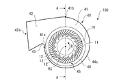
- FIG. 2 is an external view schematically showing a configuration in which the multi-blade blower 100 according to the first embodiment is viewed in parallel with the rotation axis RS.
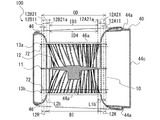
- FIG. 3 is a cross-sectional view schematically showing a cross section taken along line AA of the multi-blade blower 100 of FIG.
- the basic structure of the multi-blade blower 100 will be described with reference to FIGS. 1 to 3. It should be noted that FIGS.
- the multi-blade blower 100 is a multi-blade centrifugal blower, and has an impeller 10 for generating an air flow and a scroll casing 40 for accommodating the impeller 10 inside.
- the multi-blade blower 100 is a double suction type centrifugal blower in which air is sucked from both sides of the scroll casing 40 in the axial direction of the virtual rotating shaft RS of the impeller 10.
- the scroll casing 40 houses the impeller 10 for the multi-blade blower 100 inside, and rectifies the air blown out from the impeller 10.
- the scroll casing 40 has a scroll portion 41 and a discharge portion 42.
- the scroll portion 41 forms an air passage that converts the dynamic pressure of the air flow generated by the impeller 10 into static pressure.
- the scroll portion 41 covers the impeller 10 from the axial direction of the rotating shaft RS of the shaft portion 11b constituting the impeller 10, and has a side wall 44a formed with a suction port 45 for taking in air, and the impeller 10 of the shaft portion 11b. It has a peripheral wall 44c that surrounds the impeller 10 from the radial direction of the rotating shaft RS. Further, the scroll portion 41 is located between the discharge portion 42 and the winding start portion 41a of the peripheral wall 44c to form a curved surface, and the airflow generated by the impeller 10 is sent to the discharge port 42a via the scroll portion 41.
- the radial direction of the rotating shaft RS is a direction perpendicular to the axial direction of the rotating shaft RS.
- the internal space of the scroll portion 41 composed of the peripheral wall 44c and the side wall 44a is a space in which the air blown out from the impeller 10 flows along the peripheral wall 44c.
- the side walls 44a are arranged on both sides of the impeller 10 in the axial direction of the rotation shaft RS of the impeller 10.
- a suction port 45 is formed on the side wall 44a of the scroll casing 40 so that air can flow between the impeller 10 and the outside of the scroll casing 40.
- the suction port 45 is formed in a circular shape, and the impeller 10 is arranged so that the center of the suction port 45 and the center of the shaft portion 11b of the impeller 10 substantially coincide with each other.
- the shape of the suction port 45 is not limited to a circular shape, and may be another shape such as an elliptical shape.
- the scroll casing 40 of the multi-blade blower 100 is a double-suction type casing having side walls 44a having suction ports 45 formed on both sides of the main plate 11 in the axial direction of the rotating shaft RS of the shaft portion 11b.
- the multi-blade blower 100 has two side walls 44a in the scroll casing 40.
- the two side walls 44a are formed so as to face each other via the peripheral wall 44c. More specifically, as shown in FIG. 3, the scroll casing 40 has a first side wall 44a1 and a second side wall 44a2 as the side wall 44a.
- the first side wall 44a1 forms a first suction port 45a facing the plate surface of the main plate 11 on the side on which the first side plate 13a described later is arranged.
- the second side wall 44a2 forms a second suction port 45b facing the plate surface of the main plate 11 on the side where the second side plate 13b, which will be described later, is arranged.
- the suction port 45 described above is a general term for the first suction port 45a and the second suction port 45b.
- the suction port 45 provided on the side wall 44a is formed by a bell mouth 46. That is, the bell mouth 46 forms a suction port 45 that communicates with the space formed by the main plate 11 and the plurality of blades 12.
- the bell mouth 46 rectifies the gas sucked into the impeller 10 and causes it to flow into the suction port 10e of the impeller 10.
- the bell mouth 46 is formed so that the opening diameter gradually decreases from the outside to the inside of the scroll casing 40. Due to the configuration of the side wall 44a, the air in the vicinity of the suction port 45 smoothly flows along the bell mouth 46, and efficiently flows into the impeller 10 from the suction port 45.
- the peripheral wall 44c guides the airflow generated by the impeller 10 to the discharge port 42a along the curved wall surface.
- the peripheral wall 44c is a wall provided between the side walls 44a facing each other, and constitutes a curved surface along the rotation direction R of the impeller 10.
- the peripheral wall 44c is arranged in parallel with the axial direction of the rotation axis RS of the impeller 10, for example, and covers the impeller 10.
- the peripheral wall 44c may be inclined with respect to the axial direction of the rotating shaft RS of the impeller 10, and is not limited to the form arranged parallel to the axial direction of the rotating shaft RS.
- the peripheral wall 44c covers the impeller 10 from the radial direction of the shaft portion 11b, and constitutes an inner peripheral surface facing the plurality of blades 12, which will be described later.
- the peripheral wall 44c faces the air blowing side of the blade 12 of the impeller 10. As shown in FIG. 2, the peripheral wall 44c is located at the boundary between the discharge portion 42 and the scroll portion 41 on the side away from the tongue portion 43 from the winding start portion 41a located at the boundary between the peripheral wall 44c and the tongue portion 43. Up to the end of winding 41b, the impeller 10 is provided along the rotation direction R of the impeller 10.
- the winding start portion 41a is an upstream end portion of the airflow generated by the rotation of the impeller 10 on the peripheral wall 44c forming the curved surface
- the winding end portion 41b is a downstream end of the airflow generated by the rotation of the impeller 10. The end of the side.
- the peripheral wall 44c is formed in a spiral shape.
- the spiral shape for example, there is a shape based on a logarithmic spiral, an Archimedes spiral, an involute curve, or the like.
- the inner peripheral surface of the peripheral wall 44c constitutes a curved surface that smoothly curves along the circumferential direction of the impeller 10 from the winding start portion 41a, which is the start of spiral winding, to the winding end portion 41b, which is the end of spiral winding. ..
- the air sent out from the impeller 10 smoothly flows in the gap between the impeller 10 and the peripheral wall 44c in the direction of the discharge portion 42. Therefore, in the scroll casing 40, the static pressure of air efficiently increases from the tongue portion 43 toward the discharge portion 42.
- the discharge unit 42 forms a discharge port 42a generated by the impeller 10 and discharging the airflow that has passed through the scroll unit 41.
- the discharge portion 42 is composed of a hollow pipe having a rectangular cross section orthogonal to the flow direction of the air flowing along the peripheral wall 44c.
- the cross-sectional shape of the discharge portion 42 is not limited to a rectangle.
- the discharge unit 42 forms a flow path that guides the air that is sent out from the impeller 10 and flows in the gap between the peripheral wall 44c and the impeller 10 so as to be discharged to the outside of the scroll casing 40.
- the discharge portion 42 includes an extension plate 42b, a diffuser plate 42c, a first side plate portion 42d, a second side plate portion 42e, and the like.
- the extension plate 42b is formed integrally with the peripheral wall 44c so as to be smoothly continuous with the winding end 41b on the downstream side of the peripheral wall 44c.
- the diffuser plate 42c is formed integrally with the tongue portion 43 of the scroll casing 40 and faces the extension plate 42b.
- the diffuser plate 42c is formed at a predetermined angle with respect to the extending plate 42b so that the cross-sectional area of the flow path gradually expands along the air flow direction in the discharge portion 42.
- the first side plate portion 42d is integrally formed with the first side wall 44a1 of the scroll casing 40
- the second side plate portion 42e is integrally formed with the second side wall 44a2 on the opposite side of the scroll casing 40.
- the first side plate portion 42d and the second side plate portion 42e are formed between the extension plate 42b and the diffuser plate 42c.
- a flow path having a rectangular cross section is formed by the extension plate 42b, the diffuser plate 42c, the first side plate portion 42d, and the second side plate portion 42e.
- the tongue portion 43 is formed between the diffuser plate 42c of the discharge portion 42 and the winding start portion 41a of the peripheral wall 44c.
- the tongue portion 43 is formed with a predetermined radius of curvature, and the peripheral wall 44c is smoothly connected to the diffuser plate 42c via the tongue portion 43.
- the tongue portion 43 suppresses the inflow of air from the end of winding to the beginning of winding of the spiral flow path.
- the tongue portion 43 is provided in the upstream portion of the ventilation passage, and divides the air flow in the rotation direction R of the impeller 10 and the air flow in the discharge direction from the downstream portion of the ventilation passage toward the discharge port 42a. Has a role. Further, the static pressure of the air flow flowing into the discharge portion 42 increases while passing through the scroll casing 40, and the pressure becomes higher than that in the scroll casing 40. Therefore, the tongue portion 43 has a function of partitioning such a pressure difference.
- the impeller 10 is a centrifugal fan.
- the impeller 10 is rotationally driven by a motor or the like (not shown), and the centrifugal force generated by the rotation forcibly sends air outward in the radial direction.
- the impeller 10 is rotated in the rotation direction R indicated by the arrow by a motor or the like.
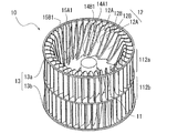
- the impeller 10 includes a disk-shaped main plate 11, an annular side plate 13, and several sheets radially arranged in the circumferential direction of the main plate 11 at the peripheral edge of the main plate 11. It has a blade 12.
- the main plate 11 may have a plate shape, and may have a shape other than a disk shape, such as a polygonal shape. Further, the thickness of the main plate 11 may be formed so that the wall thickness becomes thicker toward the center in the radial direction centered on the rotation axis RS, as shown in FIG. 3, and the rotation axis RS is formed. It may be formed to have a constant thickness in the radial direction around the center.
- a shaft portion 11b to which a motor (not shown) is connected is provided at the center of the main plate 11. The main plate 11 is rotationally driven by a motor via the shaft portion 11b.
- the main plate 11 is not limited to one composed of one plate-shaped member, and may be configured by integrally fixing a plurality of plate-shaped members.
- One end of the plurality of blades 12 is connected to the main plate 11 and the other end is connected to the side plate 13, and the blades 12 are arranged in the circumferential direction centered on the virtual rotation axis RS of the main plate 11.
- Each of the plurality of blades 12 is arranged between the main plate 11 and the side plate 13.
- the plurality of blades 12 are provided on both sides of the main plate 11 in the axial direction of the rotation shaft RS of the shaft portion 11b.
- the blades 12 are arranged at a certain distance from each other on the peripheral edge of the main plate 11. The detailed configuration of each blade 12 will be described later.
- the impeller 10 has an annular side plate 13 attached to an end portion of the shaft portion 11b opposite to the main plate 11 of the plurality of blades 12 in the axial direction of the rotating shaft RS.
- the side plate 13 is arranged in the impeller 10 so as to face the main plate 11.
- the side plate 13 maintains the positional relationship of the tips of the respective blades 12 by connecting the plurality of blades 12, and reinforces the plurality of blades 12.
- the impeller 10 has a main plate 11, a first wing portion 112a, and a second wing portion 112b.
- the first wing portion 112a and the second wing portion 112b are composed of a plurality of blades 12 and side plates 13. More specifically, the first wing portion 112a is formed by an annular first side plate 13a arranged to face the main plate 11 and a plurality of blades 12 arranged between the main plate 11 and the first side plate 13a. It is configured.
- the second wing portion 112b includes an annular second side plate 13b arranged to face the main plate 11 on the side opposite to the side where the first side plate 13a is arranged with respect to the main plate 11, and the main plate 11 and the second side plate.
- the side plate 13 is a general term for the first side plate 13a and the second side plate 13b, and the impeller 10 has the first side plate 13a on one side with respect to the main plate 11 in the axial direction of the rotating shaft RS, and the other. It has a second side plate 13b on the side of.
- the first wing portion 112a is arranged on one plate surface side of the main plate 11, and the second wing portion 112b is arranged on the other plate surface side of the main plate 11. That is, the plurality of blades 12 are provided on both sides of the main plate 11 in the axial direction of the rotation axis RS, and the first blade portion 112a and the second blade portion 112b are provided back to back via the main plate 11. ing.
- the first wing portion 112a is arranged on the left side with respect to the main plate 11, and the second wing portion 112b is arranged on the right side with respect to the main plate 11.
- first wing portion 112a and the second wing portion 112b need only be provided back to back via the main plate 11, and the first wing portion 112a is arranged on the right side of the main plate 11 and is provided on the main plate 11.
- the second wing portion 112b may be arranged on the left side.
- the blade 12 is described as a general term for the blade 12 constituting the first blade portion 112a and the blade 12 constituting the second blade portion 112b.
- the impeller 10 is formed in a tubular shape by a plurality of blades 12 arranged on the main plate 11. Then, the impeller 10 allows gas to flow into the space surrounded by the main plate 11 and the plurality of blades 12 on the side plate 13 side opposite to the main plate 11 in the axial direction of the rotating shaft RS of the shaft portion 11b.
- the suction port 10e is formed.
- blades 12 and side plates 13 are arranged on both sides of a plate surface forming the main plate 11, and suction ports 10e of the impeller 10 are formed on both sides of the plate surface forming the main plate 11.
- the impeller 10 is rotationally driven around the rotary shaft RS by being driven by a motor (not shown). As the impeller 10 rotates, the gas outside the multi-blade blower 100 passes through the suction port 45 formed in the scroll casing 40 and the suction port 10e of the impeller 10, and the main plate 11 and the plurality of blades 12 It is sucked into the space surrounded by. Then, as the impeller 10 rotates, the air sucked into the space surrounded by the main plate 11 and the plurality of blades 12 passes through the space between the blades 12 and the adjacent blades 12, and the diameter of the impeller 10 is increased. It is sent out of the direction.
- FIG. 4 is a perspective view of the impeller 10 constituting the multi-blade blower 100 according to the first embodiment.
- FIG. 5 is a side view of the impeller 10 of FIG.
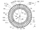
- FIG. 6 is a schematic view showing the blade 12 in the CC line cross section of the impeller 10 of FIG.
- FIG. 7 is a schematic view showing the blade 12 in the DD line cross section of the impeller 10 of FIG.
- the intermediate position MP of the impeller 10 shown in FIG. 5 indicates an intermediate position in the axial direction of the rotation axis RS in the plurality of blades 12 constituting the first blade portion 112a.
- each of the plurality of blades 12 has a first region located closer to the main plate 11 than the intermediate position MP in the axial direction of the rotation axis RS, and a second region located closer to the side plate 13 than the first region.
- the CC line cross section shown in FIG. 5 is a cross section of a plurality of blades 12 on the main plate 11 side of the impeller 10, that is, the main plate side blade region 122a, which is the first region.
- the cross section of the blade 12 on the main plate 11 side is the first plane 71 perpendicular to the rotation axis RS, and the portion of the impeller 10 near the main plate 11 is cut off, which is the first cross section of the impeller 10.
- the portion of the impeller 10 closer to the main plate 11 is, for example, a portion closer to the main plate 11 than the intermediate position of the main plate side blade region 122a in the axial direction of the rotating shaft RS, or a blade in the axial direction of the rotating shaft RS. This is a portion where the end portion of the main plate 12 on the 11 side is located.
- the DD line cross section shown in FIG. 5 is a cross section of a plurality of blades 12 on the side plate 13 side of the impeller 10, that is, the side plate side blade region 122b which is the second region.
- the cross section of the blade 12 on the side plate 13 side is a second plane 72 perpendicular to the rotation axis RS, and the portion of the impeller 10 near the side plate 13 is cut off, which is the second cross section of the impeller 10.
- the portion of the impeller 10 closer to the side plate 13 is, for example, a portion closer to the side plate 13 than the intermediate position of the side plate side blade region 122b in the axial direction of the rotating shaft RS, or a blade in the axial direction of the rotating shaft RS. This is a portion where the end portion of the side plate 12 on the 13 side is located.
- the basic configuration of the blade 12 in the second blade portion 112b is the same as the basic configuration of the blade 12 in the first blade portion 112a. That is, the intermediate position MP of the impeller 10 shown in FIG. 5 indicates an intermediate position in the axial direction of the rotation axis RS in the plurality of blades 12 constituting the second blade portion 112b. Then, in the plurality of blades 12 constituting the second blade portion 112b, the region from the intermediate position MP in the axial direction of the rotating shaft RS to the main plate 11 is defined as the main plate side blade region 122a which is the first region of the impeller 10.
- the region from the intermediate position MP in the axial direction of the rotating shaft RS to the end portion on the second side plate 13b side is the side plate side which is the second region of the impeller 10.
- the blade region 122b is the same, but the configuration of the impeller 10 is limited to this configuration. Instead, the first wing portion 112a and the second wing portion 112b may have different configurations.
- the configuration of the blade 12 described below may be possessed by both the first blade portion 112a and the second blade portion 112b, or may be possessed by either one.
- the detailed configuration of the blade 12 will be described with reference to FIGS. 4 to 7.
- the plurality of blades 12 have a plurality of first blades 12A and a plurality of second blades 12B.
- the first blade 12A and one or a plurality of second blades 12B are alternately arranged in the circumferential direction of the impeller 10.
- two second blades 12B are arranged between the first blade 12A and the first blade 12A arranged adjacent to each other in the rotation direction R.
- the number of the second blades 12B arranged between the first blade 12A and the first blade 12A arranged adjacent to each other in the rotation direction R is not limited to two, and one or three or more. It may be. That is, at least one second blade 12B of the plurality of second blades 12B is arranged between the two first blades 12A adjacent to each other in the circumferential direction among the plurality of first blades 12A.
- the first blade 12A is an inner peripheral end 14A located on the rotation axis RS side in the radial direction centered on the rotation axis RS in the first cross section of the impeller 10 cut by the first plane 71 perpendicular to the rotation axis RS. And an outer peripheral end 15A located on the outer peripheral side of the inner peripheral end 14A in the radial direction.
- the inner peripheral end 14A is arranged in front of the outer peripheral end 15A in the rotation direction R of the impeller 10.
- the inner peripheral end 14A is the front edge 14A1 of the first blade 12A
- the outer peripheral end 15A is the trailing edge 15A1 of the first blade 12A.
- 14 first blades 12A are arranged on the impeller 10, but the number of the first blades 12A is not limited to 14, and may be less than 14. It may be more than 14 sheets.
- the second blade 12B is an inner peripheral end 14B located on the rotation axis RS side in the radial direction centered on the rotation axis RS in the first cross section of the impeller 10 cut by the first plane 71 perpendicular to the rotation axis RS. And an outer peripheral end 15B located on the outer peripheral side of the inner peripheral end 14B in the radial direction.
- the inner peripheral end 14B is arranged in front of the outer peripheral end 15B in the rotation direction R of the impeller 10.
- the inner peripheral end 14B is the front edge 14B1 of the second blade 12B
- the outer peripheral end 15B is the trailing edge 15B1 of the second blade 12B.
- 28 second blades 12B are arranged on the impeller 10, but the number of the second blades 12B is not limited to 28, and may be less than 28. Well, it may be more than 28 sheets.
- the wingspan of the first blade 12A is the same as that of the second blade 12B. It is equal to the wingspan.
- the wingspan of the first blade 12A is longer than the wingspan of the second blade 12B in the portion closer to the main plate 11 than the intermediate position MP in the direction along the rotation axis RS. And the closer it is to the main plate 11, the longer it becomes.
- the wingspan of the first blade 12A is longer than the wingspan of the second blade 12B at least in a part of the direction along the rotation axis RS.
- the blade length used here is the length of the first blade 12A in the radial direction of the impeller 10 and the length of the second blade 12B in the radial direction of the impeller 10.
- the diameter of the circle C1 passing through the inner peripheral ends 14A of the plurality of first blades 12A centered on the rotation axis RS That is, the inner diameter of the first blade 12A is defined as the inner diameter ID1.
- the diameter of the circle C3 passing through the outer peripheral ends 15A of the plurality of first blades 12A centered on the rotation axis RS, that is, the outer diameter of the first blade 12A is defined as the outer diameter OD1.
- the ratio of the inner diameter of the first blade 12A to the outer diameter of the first blade 12A is 0.7 or less. That is, the plurality of first blades 12A has an inner diameter ID1 composed of the inner peripheral ends 14A of the plurality of first blades 12A and an outer diameter OD1 composed of the outer peripheral ends 15A of the plurality of first blades 12A.
- the ratio with is 0.7 or less.
- the blade length in the cross section perpendicular to the rotation axis is shorter than the blade width dimension in the rotation axis direction.
- the maximum blade length of the first blade 12A that is, the blade length at the end of the first blade 12A near the main plate 11, is the width dimension W of the first blade 12A in the rotation axis direction (see FIG. 5). Is shorter than.
- the diameter of the circle C2 passing through the inner peripheral ends 14B of the plurality of second blades 12B centered on the rotation axis RS, that is, the inner diameter of the second blade 12B is defined as the inner diameter ID2 larger than the inner diameter ID1.
- the wingspan L2a of the second blade 12B in the first cross section is shorter than the wingspan L1a of the first blade 12A in the same cross section (wing length L2a ⁇ wing length L1a).
- the ratio of the inner diameter of the second blade 12B to the outer diameter of the second blade 12B is 0.7 or less.
- the plurality of second blades 12B have an inner diameter ID2 composed of the inner peripheral ends 14B of the plurality of second blades 12B and an outer diameter OD2 composed of the outer peripheral ends 15B of the plurality of second blades 12B.
- the ratio with is 0.7 or less.
- the diameter of the circle C7 passing through the inner peripheral end 14A of the first blade 12A centered on the rotation axis RS is defined.
- Inner diameter ID3 is larger than the inner diameter ID1 of the first cross section (inner diameter ID3> inner diameter ID1).
- the diameter of the circle C8 passing through the outer peripheral end 15A of the first blade 12A centered on the rotation axis RS is defined as the outer diameter OD3.
- the diameter of the circle C7 passing through the inner peripheral end 14B of the second blade 12B centered on the rotation axis RS is defined as the inner diameter ID4.
- the diameter of the circle C8 passing through the outer peripheral end 15B of the second blade 12B centered on the rotation axis RS is defined as the outer diameter OD4.
- Blade length L2b (outer diameter OD4-inner diameter ID4) / 2).
- the ratio of the blade inner diameter of the blade 12 to the blade outer diameter of the blade 12 is 0.7 or less.
- the inner diameter of the plurality of blades 12 is composed of the inner peripheral ends of the plurality of blades 12. That is, the blade inner diameter of the plurality of blades 12 is composed of the front edges 14A1 of the plurality of blades 12.
- the blade outer diameter of the plurality of blades 12 is composed of the outer peripheral ends of the plurality of blades 12. That is, the blade outer diameter of the plurality of blades 12 is composed of the trailing edge 15A1 and the trailing edge 15B1 of the plurality of blades 12.
- the first blade 12A has a relationship of blade length L1a> blade length L1b in comparison between the first cross section shown in FIG. 6 and the second cross section shown in FIG. 7. That is, each of the plurality of blades 12 is formed so that the blade length in the first region is longer than the blade length in the second region. More specifically, the first blade 12A is formed so that the blade length decreases from the main plate 11 side to the side plate 13 side in the axial direction of the rotation shaft RS. Similarly, the second blade 12B has a relationship of blade length L2a> blade length L2b in comparison between the first cross section shown in FIG. 6 and the second cross section shown in FIG. 7. That is, the second blade 12B is formed so that the blade length decreases from the main plate 11 side to the side plate 13 side in the axial direction of the rotation shaft RS.
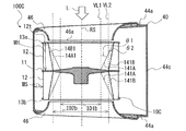
- the front edges of the first blade 12A and the second blade 12B are inclined so that the inner diameter of the blade increases from the main plate 11 side to the side plate 13 side. That is, the plurality of blades 12 have inclined portions 141A in which the inner peripheral end 14A constituting the front edge 14A1 is inclined away from the rotation axis RS so that the inner diameter of the blades increases from the main plate 11 side to the side plate 13 side. Is forming. Similarly, the plurality of blades 12 have inclined portions 141B in which the inner peripheral end 14B constituting the front edge 14B1 increases away from the rotation axis RS so that the inner diameter of the blades increases from the main plate 11 side to the side plate 13 side. Is forming.
- the first blade 12A has a first sirocco blade portion 12A1 configured as a forward vane and a first turbo blade portion 12A2 configured as a rearward blade.
- the first sirocco blade portion 12A1 constitutes the outer peripheral side of the first blade 12A
- the first turbo blade portion 12A2 constitutes the inner peripheral side of the first blade 12A. That is, the first blade 12A is configured in the order of the first turbo blade portion 12A2 and the first sirocco blade portion 12A1 from the rotation axis RS toward the outer peripheral side in the radial direction of the impeller 10.
- the first turbo blade portion 12A2 and the first sirocco blade portion 12A1 are integrally formed.
- the first turbo blade portion 12A2 constitutes the front edge 14A1 of the first blade 12A
- the first sirocco blade portion 12A1 constitutes the trailing edge 15A1 of the first blade 12A.
- the first turbo blade portion 12A2 extends linearly from the inner peripheral end 14A constituting the front edge 14A1 toward the outer peripheral side in the radial direction of the impeller 10.
- the region constituting the first sirocco blade portion 12A1 of the first blade 12A is defined as the first sirocco region 12A11, and the region constituting the first turbo blade portion 12A2 of the first blade 12A is the first. It is defined as 1 turbo region 12A21.
- the first turbo region 12A21 is larger than the first sirocco region 12A11 in the radial direction of the impeller 10.
- the impeller 10 has a first sirocco region 12A11 ⁇ third in the radial direction of the impeller 10 in any region of the main plate side blade region 122a which is the first region and the side plate side blade region 122b which is the second region. It has a relationship of 1 turbo region 12A21.
- the impeller 10 and the first blade 12A are the first turbo blades in the radial direction of the impeller 10 in any region of the main plate side blade region 122a which is the first region and the side plate side blade region 122b which is the second region.
- the proportion of the portion 12A2 is larger than the proportion of the first sirocco blade portion 12A1.
- the second blade 12B has a second sirocco blade portion 12B1 configured as a forward vane and a second turbo blade portion 12B2 configured as a rearward blade. ..
- the second sirocco blade portion 12B1 constitutes the outer peripheral side of the second blade 12B
- the second turbo blade portion 12B2 constitutes the inner peripheral side of the second blade 12B. That is, the second blade 12B is configured in the order of the second turbo blade portion 12B2 and the second sirocco blade portion 12B1 from the rotation axis RS toward the outer peripheral side in the radial direction of the impeller 10.
- the second turbo blade portion 12B2 and the second sirocco blade portion 12B1 are integrally formed.
- the second turbo blade portion 12B2 constitutes the front edge 14B1 of the second blade 12B
- the second sirocco blade portion 12B1 constitutes the trailing edge 15B1 of the second blade 12B.
- the second turbo blade portion 12B2 extends linearly from the inner peripheral end 14B constituting the front edge 14B1 toward the outer peripheral side in the radial direction of the impeller 10.
- the region constituting the second sirocco blade portion 12B1 of the second blade 12B is defined as the second sirocco region 12B11, and the region constituting the second turbo blade portion 12B2 of the second blade 12B is the first.
- 2 Turbo region 12B21 is defined.
- the second turbo region 12B21 is larger than the second sirocco region 12B11 in the radial direction of the impeller 10.
- the impeller 10 has a second sirocco region 12B11 ⁇ third in the radial direction of the impeller 10 in any region of the main plate side blade region 122a which is the first region and the side plate side blade region 122b which is the second region. It has a relationship of 2 turbo regions 12B21.
- the impeller 10 and the second blade 12B have a second turbo blade in the radial direction of the impeller 10 in any region of the main plate side blade region 122a which is the first region and the side plate side blade region 122b which is the second region.
- the proportion of the portion 12B2 is larger than the proportion of the second sirocco wing portion 12B1.
- the plurality of blades 12 have a turbo blade region larger than a sirocco blade region in the radial direction of the impeller 10 in any region of the main plate side blade region 122a and the side plate side blade region 122b. .. That is, in the plurality of blades 12, the ratio of the turbo blades is larger than the ratio of the sirocco blades in the radial direction of the impeller 10 in both the main plate side blade region 122a and the side plate side blade region 122b, and the sirocco. It has a relationship of region ⁇ turbo region.
- the ratio of the turbo blade portion in the radial direction is larger than the ratio of the sirocco blade portion in the first region and the second region.
- the ratio of the turbo blade portion is larger than the ratio of the sirocco blade portion in the radial direction of the impeller 10 in any region of the main plate side blade region 122a and the side plate side blade region 122b, and the sirocco It is not limited to those having a relationship of region ⁇ turbo region.
- the ratio of the turbo blade portion in the radial direction may be equal to the ratio of the sirocco blade portion or smaller than the ratio of the sirocco blade portion in the first region and the second region.
- the outlet angle of the first sirocco blade portion 12A1 of the first blade 12A in the first cross section is defined as the exit angle ⁇ 1.
- the exit angle ⁇ 1 is the angle formed by the tangent line TL1 of the circle and the center line CL1 of the first sirocco wing portion 12A1 at the outer peripheral end 15A at the intersection of the arc of the circle C3 centered on the rotation axis RS and the outer peripheral end 15A. Define.
- This exit angle ⁇ 1 is an angle larger than 90 degrees.
- the outlet angle of the second sirocco blade portion 12B1 of the second blade 12B in the same cross section is defined as the outlet angle ⁇ 2.
- the exit angle ⁇ 2 is the angle formed by the tangent line TL2 of the circle and the center line CL2 of the second sirocco wing portion 12B1 at the outer peripheral end 15B at the intersection of the arc of the circle C3 centered on the rotation axis RS and the outer peripheral end 15B. Define.
- the exit angle ⁇ 2 is an angle larger than 90 degrees.
- the first sirocco wing portion 12A1 and the second sirocco wing portion 12B1 are formed in an arc shape so as to be convex in the direction opposite to the rotation direction R when viewed in parallel with the rotation axis RS.
- the outlet angle ⁇ 1 of the first sirocco wing portion 12A1 and the exit angle ⁇ 2 of the second sirocco wing portion 12B1 are equal even in the second cross section. That is, the plurality of blades 12 have sirocco blades forming forward blades formed at an exit angle larger than 90 degrees from the main plate 11 to the side plates 13.
- the outlet angle of the first turbo blade portion 12A2 of the first blade 12A in the first cross section is defined as the exit angle ⁇ 1.
- the exit angle ⁇ 1 is defined as the angle formed by the tangent line TL3 of the circle and the center line CL3 of the first turbo blade portion 12A2 at the intersection of the arc of the circle C4 centered on the rotation axis RS and the first turbo blade portion 12A2. To do.
- This exit angle ⁇ 1 is an angle smaller than 90 degrees.
- the outlet angle of the second turbo blade portion 12B2 of the second blade 12B in the same cross section is defined as the outlet angle ⁇ 2.
- the exit angle ⁇ 2 is defined as the angle formed by the tangent line TL4 of the circle and the center line CL4 of the second turbo blade portion 12B2 at the intersection of the arc of the circle C4 centered on the rotation axis RS and the second turbo blade portion 12B2. To do.
- the exit angle ⁇ 2 is an angle smaller than 90 degrees.
- the outlet angle ⁇ 1 of the first turbo blade portion 12A2 and the outlet angle ⁇ 2 of the second turbo blade portion 12B2 are equal even in the second cross section. Further, the exit angle ⁇ 1 and the exit angle ⁇ 2 are angles smaller than 90 degrees.
- the first blade 12A has a first radial blade portion 12A3 as a connecting portion between the first turbo blade portion 12A2 and the first sirocco blade portion 12A1.
- the first radial blade portion 12A3 is a portion configured as a radial blade extending linearly in the radial direction of the impeller 10.
- the second blade 12B has a second radial blade portion 12B3 as a connecting portion between the second turbo blade portion 12B2 and the second sirocco blade portion 12B1.
- the second radial blade portion 12B3 is a portion configured as a radial blade extending linearly in the radial direction of the impeller 10.
- the blade angles of the first radial blade portion 12A3 and the second radial blade portion 12B3 are 90 degrees. More specifically, the angle formed by the tangent line at the intersection of the center line of the first radial wing portion 12A3 and the circle C5 centered on the rotation axis RS and the center line of the first radial wing portion 12A3 is 90 degrees. Further, the angle formed by the tangent line at the intersection of the center line of the second radial wing portion 12B3 and the circle C5 centered on the rotation axis RS and the center line of the second radial wing portion 12B3 is 90 degrees.
- FIG. 8 is a schematic view showing a cross section of the impeller 10A according to a modified example of the impeller 10 shown in FIG.
- the impeller 10A according to the modified example shown in FIG. 8 is a schematic view showing the vanes 12 at the positions of the impeller 10 shown in FIG. 5 in the CC line cross section.
- the impeller 10A has a plurality of blades 12.
- the plurality of blades 12 are composed of the first blade 12A. That is, the impeller 10A does not have the second blade 12B.
- the blade 12 may be composed of only the first blade 12A.
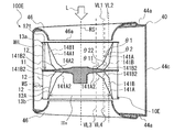
- FIG. 9 is a conceptual diagram illustrating an impeller 10 connected to a motor 50 in the multi-blade blower 100 according to the first embodiment.
- FIG. 10 is a schematic view showing the blade 12 in the CC line cross section of the first blade portion 112a of FIG.
- FIG. 11 is a schematic view showing the blade 12 in the CC line cross section of the second blade portion 112b of FIG.
- FIG. 12 is a schematic view showing the blade 12 in the DD line cross section of the first blade portion 112a of FIG.
- FIG. 13 is a schematic view showing the blade 12 in the DD line cross section of the second blade portion 112b of FIG.
- the distance between the blades 12 adjacent to each other in the circumferential direction will be described with reference to FIGS. 9 to 13.
- 10 and 12 are cross sections of the impeller 10 as viewed in the direction of the arrow VW1 of FIG. 11 and 13 are cross sections of the impeller 10 as viewed in the direction of the arrow VW2 of FIG.
- the distance between the blades of the plurality of blades 12 is on the front edge 14A1 side. It spreads toward the trailing edge 15A1 side.
- the space between the blades of the plurality of blades 12 widens from the front edge 14B1 side toward the trailing edge 15B1 side.
- the space between the blades in the turbo blade portion composed of the first turbo blade portion 12A2 and the second turbo blade portion 12B2 extends from the inner peripheral side to the outer peripheral side.
- the space between the blades in the sirocco blade portion composed of the first sirocco blade portion 12A1 and the second sirocco blade portion 12B1 is wider than the space between the blades of the turbo blade portion, and extends from the inner peripheral side to the outer peripheral side. That is, the space between the blades between the first turbo blade portion 12A2 and the second turbo blade portion 12B2, or the space between the adjacent second turbo blade portions 12B2, extends from the inner peripheral side to the outer peripheral side. Further, the distance between the blades of the first sirocco blade portion 12A1 and the second sirocco blade portion 12B1 or the distance between the adjacent second sirocco blade portions 12B1 is wider and the inner circumference than the distance between the blades of the turbo blade portion. It extends from the side to the outer circumference.
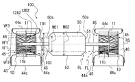
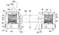
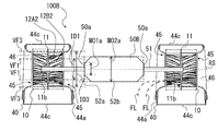
- the multi-blade blower 100 may have a motor 50 for rotating the main plate 11 of the impeller 10 in addition to the impeller 10 and the scroll casing 40. That is, the multi-blade blower 100 may have an impeller 10, a scroll casing 40 that houses the impeller 10, and a motor 50 that drives the impeller 10.
- the motor shaft 51 which is the rotation axis of the motor 50, penetrates the side surface of the scroll casing 40 and is inserted into the scroll casing 40.
- the motor shaft 51 is connected to and fixed to the main plate 11 of the impeller 10.
- the motor shaft 51 is connected to the main plate 11 on the forming side of the first wing portion 112a and the motor 50 is arranged, and the motor 50 is arranged on the forming side of the second wing portion 112b with respect to the main plate 11.
- the shaft 51 is not connected and the motor 50 is not arranged. That is, in the multi-blade blower 100, the motor 50 is arranged so as to face the first blade portion 112a.
- the difference in structure between the first wing portion 112a formed on the side where the motor 50 is arranged and the second wing portion 112b formed on the side where the motor 50 is not arranged will be described.
- the blades of the first blade portion 112a and the second blade portion 112b are inclined so that the front edge 14A1 and the front edge 14B1 are separated from the rotation axis RS so that the inner diameter of the blade increases from the main plate 11 side to the side plate 13 side. It has a region 142.
- the blade inclination region 142 has an inner diameter of the blades increasing from the main plate 11 side to the side plate 13 side.
- the front edge 14A1 is inclined so as to be separated from the rotation axis RS.
- the plurality of blades 12 form a gradient on the inner peripheral side by the blade inclination region 142.
- the blade inclination region 142 of the first blade portion 112a is arranged so as to face the motor 50.
- the blade inclination region 142 is between the circle C1 passing through the inner peripheral end 14A closer to the main plate 11 in the plurality of first blades 12A and the circle C7 passing through the inner peripheral end 14A closer to the side plate 13 in the plurality of first blades 12A. At least formed in the area. That is, the blade inclined region 142 has the inner diameter ID1 of the plurality of first blades 12A in the first cross section closer to the main plate 11 than the intermediate position MP, and the plurality of first blades in the second cross section closer to the side plate 13 than the intermediate position MP. It is formed at least in the region between the inner diameter ID 3 of 12A.
- the blade inclined region 142 is an region in which the inclined portion 141A and the inclined portion 141B described above are formed.
- the distance between the blades 12 on the main plate 11 side is defined as the first blade distance a1.
- the distance between the blades 12 on the main plate 11 side is defined as the second blade distance b1.
- the blade inclination region 142 has a plurality of blades 12 forming a first blade-to-blade a1 and a second blade-to-blade b1 on one surface side and the other surface side of the main plate 11.
- the first blade spacing a1 is between the blades of the blade tilting region 142 of the first blade portion 112a
- the second blade spacing b1 is between the blades of the blade tilting region 142 of the second blade portion 112b.
- the distance between the blades of the first blades 12A arranged adjacent to the circumferential CD is the distance between the blades a1. Defined as -1. Further, among the first blades 12A arranged adjacent to the circumferential CD, the distance between the blades between the first blade 12A and the second blade 12B arranged adjacent to the circumferential CD is set. It is defined as 1-wing a1-2. That is, in the first blade a1-1, the distance between the blades between the first blade 12A and the second blade 12B arranged adjacent to the circumferential CD is defined as the first blade a1-2.
- the distance between the blades of the second blades 12B arranged adjacent to the circumferential CD is defined as the first blade a1-3.
- the distance between the blades of the second blades 12B arranged adjacent to the circumferential CD is defined as the first blade a1-3.
- the distance between the blades between the second blade 12B and the first blade 12A arranged adjacent to the circumferential CD is set. It is defined as 1-blade a1-4.
- the distance between the blades between the second blade 12B and the first blade 12A arranged adjacent to the circumferential CD is defined as the first blade a1-4.
- the first blade a1-1, the first blade a1-2, the first blade a1-3, and the first blade a1-4 are between the blades 12 in the blade inclination region 142 of the first blade portion 112a. The distance.
- the distance between the blades of the first blades 12A arranged adjacent to the circumferential CD is defined as the second blade distance b1-1. ..
- the distance between the blades between the first blade 12A and the second blade 12B arranged adjacent to the circumferential CD is set. It is defined as b1-2 between two wings. That is, in the second blade-to-blade b1-1, the distance between the blades between the first blade 12A and the second blade 12B arranged adjacent to the circumferential CD is defined as the second blade-to-blade b1-2.
- the distance between the blades of the second blades 12B arranged adjacent to the circumferential CD is defined as the second blade b1-3.
- the distance between the blades of the second blades 12B arranged adjacent to the circumferential CD is defined as the second blade-to-blade b1-3.
- the distance between the blades between the second blade 12B and the first blade 12A arranged adjacent to the circumferential CD is set. It is defined as b1-4 between two wings.
- the distance between the blades between the second blade 12B and the first blade 12A arranged adjacent to the circumferential CD is defined as the second blade-to-blade b1-4.
- the second wing b1-1, the second wing b1-2, the second wing b1-3, and the second wing b1-4 are between the blades 12 in the blade inclination region 142 of the second wing portion 112b. The distance.
- the first blade spacing a1 and the second blade spacing b1 are distances measured at positions separated from the rotating shaft RS by the same distance in the radial direction of the rotating shaft RS of the impeller 10.
- the first blade spacing a1-1 and the second blade spacing b1-1 are distances measured at positions separated from the rotating shaft RS by the same distance in the radial direction of the rotating shaft RS of the impeller 10.
- the first blade spacing a1-2 and the second blade spacing b1-2 are distances measured at positions separated from the rotating shaft RS by the same distance in the radial direction of the rotating shaft RS of the impeller 10.
- first blade spacing a1-3 and the second blade spacing b1-3 are distances measured at positions separated from the rotating shaft RS by the same distance in the radial direction of the rotating shaft RS of the impeller 10.
- first blade spacing a1-4 and the second blade spacing b1-4 are distances measured at positions separated from the rotating shaft RS by the same distance in the radial direction of the rotating shaft RS of the impeller 10.
- the space between the first blades a1-1 of the first blade portion 112a on the side where the motor 50 is arranged is between the second blades of the second blade portion 112b on the side where the motor 50 is not arranged. It is formed so as to be larger than b1-1 (first wing a1-1> second wing b1-1).
- the first wing a1-2 of the first wing 112a on the side where the motor 50 is arranged is the second wing b1- of the second wing 112b on the side where the motor 50 is not arranged. It is formed so as to be larger than 2 (first wing a1-2> second wing b1-2).
- the first wing a1-3 of the first wing 112a on the side where the motor 50 is arranged is the second wing b1- of the second wing 112b on the side where the motor 50 is not arranged. It is formed so as to be larger than 3 (first wing a1-3> second wing b1-3).
- the first wing a1-4 of the first wing 112a on the side where the motor 50 is arranged is the second wing b1- of the second wing 112b on the side where the motor 50 is not arranged. It is formed so as to be larger than 4 (first wing a1-4> second wing b1-4).
- the first blades a1 of the blades 12 forming the first blade portion 112a on the side where the motor 50 is arranged form the second blade portion 112b on the side where the motor 50 is not arranged. It is formed so as to be larger than the two blades b1 (first blade a1> second blade b1). Then, in the multi-blade blower 100, the first blades a1 of the plurality of blades 12 constituting the first blade portion 112a on the side where the motor 50 is arranged constitute the second blade portion 112b on the side where the motor 50 is not arranged. It has a region formed larger than the second blade b1 of the plurality of blades 12.
- the first blade spacing a1 of the plurality of first blades 12A constituting the first blade portion 112a is the second blade portion 112b. It is formed so as to be larger than the second blade interval b1 of the plurality of first blades 12A constituting the above.
- FIG. 12 is a cross section of the impeller 10 on the side plate 13 side of the first blade portion 112a.
- the distance between the blades 12 on the side plate 13 side is defined as the first blade distance a2.
- FIG. 10 is a cross section of the impeller 10 on the main plate 11 side in the first blade portion 112a.
- the impeller 10 is formed so that the first blade spacing a2 on the side plate 13 side of the first blade portion 112a is larger than the first blade spacing a1 on the main plate 11 side of the first blade portion 112a (first blade portion 112a). Between wings a1 ⁇ first between wings a2).
- one cross section of the impeller 10 is compared with each other, but this configuration is applied to the entire impeller 10. That is, in the impeller 10, even in the entire main plate side blade region 122a and the entire side plate side blade region 122b, the first blade spacing a2 on the side plate 13 side of the first blade portion 112a is on the main plate 11 side of the first blade portion 112a. It is formed so as to be larger than the first blade spacing a1 of the above (first blade spacing a1 ⁇ first blade spacing a2).
- the maximum blade spacing (a2max) in the side plate side blade region 122b is the maximum blade spacing (a1max) in the main plate side blade region 122a. ) (Maximum blade spacing (a1max) ⁇ maximum blade spacing (a2max)).
- FIG. 13 is a cross section of the impeller 10 on the side plate 13 side of the second wing portion 112b. As shown in FIG. 13, in the second blade portion 112b, the distance between the blades 12 on the side plate 13 side is defined as the second blade-to-blade b2.
- FIG. 11 is a cross section of the impeller 10 on the main plate 11 side in the second blade portion 112b. The impeller 10 is formed so that the second blade spacing b2 on the side plate 13 side of the second blade portion 112b is larger than the second blade spacing b1 on the main plate 11 side of the second blade portion 112b (second blade portion 112b). Between wings b1 ⁇ b between second wings b2).
- FIGS. 13 is a cross section of the impeller 10 on the side plate 13 side of the second wing portion 112b.
- the distance between the blades 12 on the side plate 13 side is defined as the second blade-to-blade b2.
- FIG. 11 is a cross section of the impeller 10 on the
- one cross section of the impeller 10 is compared with each other, but this configuration is applied to the entire impeller 10. That is, in the impeller 10, even in the entire main plate side blade region 122a and the entire side plate side blade region 122b, the second blade inter-b2 on the side plate 13 side of the second blade portion 112b is on the main plate 11 side of the second blade portion 112b. It is formed so as to be larger than the second blade interval b1 of the above (second blade interval b1 ⁇ second blade interval b2).
- the maximum blade spacing (b2max) in the side plate side blade region 122b is the maximum blade spacing (b1max) in the main plate side blade region 122a. ) (Maximum blade spacing (b1max) ⁇ maximum blade spacing (b2max)).
- the first blade spacing a1 on the main plate 11 side of the first blade portion 112a shown in FIG. 10 is the second blade spacing b1 on the main plate 11 side of the second blade portion 112b shown in FIG. It is formed so as to be larger than (1st wing a1> 2nd wing b1).
- one cross section of the impeller 10 is compared with each other, but this configuration is applied to the entire impeller 10. That is, the impeller 10 also covers the entire main plate side blade region 122a of the first blade portion 112a and the entire main plate side blade region 122a of the second blade portion 112b between the first blades of the first blade portion 112a on the main plate 11 side.
- a1 is formed so as to be larger than the second blade interval b1 on the main plate 11 side of the second blade portion 112b (first blade interval a1> second blade interval b1). Then, in the impeller 10, the maximum blade spacing (a1max) in the main plate side blade region 122a of the first blade portion 112a is larger (maximum) than the maximum blade spacing (b1max) in the main plate side blade region 122a of the second blade portion 112b. Between blades (b1max) ⁇ maximum blade distance (a1max)).
- the first blade spacing a2 on the side plate 13 side of the first blade portion 112a shown in FIG. 12 is the second blade spacing b2 on the side plate 13 side of the second blade portion 112b shown in FIG. It is formed so as to have the above size (first blade interval a2 ⁇ second blade interval b2).
- FIGS. 12 and 13 one cross section of the impeller 10 is compared with each other, but this configuration is applied to the entire impeller 10. That is, the impeller 10 is also between the first blades on the side plate 13 side of the first blade portion 112a in the entire side plate side blade region 122b of the first blade portion 112a and the entire side plate side blade region 122b of the second blade portion 112b.
- the a2 is formed so as to have a size equal to or larger than the second wing b2 on the side plate 13 side of the second wing 112b (first wing a2 ⁇ second wing b2). Then, in the impeller 10, the maximum blade spacing (a2max) in the side plate side blade region 122b of the first blade portion 112a is larger than the maximum blade spacing (b2max) in the side plate side blade region 122b of the second blade portion 112b. It is formed like this.
- the first blade spacing a2 and the second blade spacing b2 are distances measured at positions separated from the rotating shaft RS by the same distance in the radial direction of the rotating shaft RS of the impeller 10.
- the first blade spacing a2 on the side plate 13 side of the first blade portion 112a shown in FIG. 12 is the second blade spacing b1 on the main plate 11 side of the second blade portion 112b shown in FIG. It is formed so as to be larger than (1st wing a2> 2nd wing b1).
- one cross section of the impeller 10 is compared with each other, but this configuration is applied to the entire impeller 10. That is, the impeller 10 is also between the first blades on the side plate 13 side of the first blade portion 112a in the entire side plate side blade region 122b of the first blade portion 112a and the entire main plate side blade region 122a of the second blade portion 112b.
- a2 is formed so as to be larger than the second blade interval b1 on the main plate 11 side of the second blade portion 112b (first blade interval a2> second blade interval b1). Then, in the impeller 10, the maximum blade spacing (a2max) in the side plate side blade region 122b of the first blade portion 112a is larger (maximum) than the maximum blade spacing (b1max) in the main plate side blade region 122a of the second blade portion 112b. Between blades (b1max) ⁇ maximum blade distance (a2max)).
- the first blade spacing a2 and the second blade spacing b1 are distances measured at positions separated from the rotating shaft RS by the same distance in the radial direction of the rotating shaft RS of the impeller 10.
- the main plate side blade region 122a on the main plate 11 side of the impeller 10 is the first region
- the side plate side blade region 122b on the side plate 13 side of the impeller 10 is the second region. Therefore, in the impeller 10 and the multi-blade blower 100, the first blade spacing a1 in the first region is formed larger than the second blade spacing b1 in the first region (first blade spacing a1> second blade spacing). b1), the first wing a2 in the second region is formed to have a size equal to or larger than the second wing b2 in the second region (first wing a2 ⁇ second wing b2).
- the first blade spacing a2 in the second region is formed larger than the first blade spacing a1 in the first region (first blade spacing a1 ⁇ first blade).
- the space a2) and the second blade space b2 in the second region may be formed larger than the second blade space b1 in the first region (second blade space b1 ⁇ second blade space b2). That is, in the impeller 10 and the multi-blade blower 100, the space between the blades on the side plate 13 side may be formed larger than the space between the blades on the main plate 11 side.
- the impeller 10 and the multi-blade blower 100 may be formed so that the first blade spacing a2 in the second region is larger than the second blade spacing b1 in the first region. (1st wing a2> 2nd wing b1). Therefore, in the impeller 10 of the multi-blade blower 100, the blades of the plurality of blades 12 constituting the first blade portion 112a on the side where the motor 50 is arranged have the second blade portion 112b on the side where the motor 50 is not arranged. It is formed so as to have a size larger than that between the blades of the plurality of blades 12 that constitute the blade. Further, the impeller 10 of the multi-blade blower 100 is formed so that the space between the blades of the plurality of blades 12 on the side plate 13 side is larger than the space between the blades of the plurality of blades 12 on the main plate 11 side.
- FIG. 14 is a schematic view showing the relationship between the impeller 10 and the bell mouth 46 in the AA line cross section of the multi-blade blower 100 of FIG.
- FIG. 15 is a schematic view showing the relationship between the blade 12 and the bell mouth 46 when viewed in parallel with the rotation axis RS in the second cross section of the impeller 10 of FIG.
- the blade outer diameter OD composed of the outer peripheral ends of the plurality of blades 12 is larger than the inner diameter BI of the bell mouth 46 constituting the scroll casing 40.
- the first turbo region 12A21 is larger than the first sirocco region 12A11 in the radial direction with respect to the rotating shaft RS. That is, in the impeller 10 and the first blade 12A, the ratio of the first turbo blade portion 12A2 is larger than the ratio of the first sirocco blade portion 12A1 in the radial direction with respect to the rotation axis RS, and the ratio of the first sirocco blade portion 12A1 ⁇ 1st It has a relationship of turbo blade portion 12A2.
- the relationship between the ratio of the first sirocco blade portion 12A1 and the first turbo blade portion 12A2 in the radial direction of the rotation axis RS is either the main plate side blade region 122a which is the first region or the side plate side blade region 122b which is the second region. It also holds in the area of.
- the ratio of the first turbo blade portion 12A2 is larger than the ratio of the first sirocco blade portion 12A1 in the radial direction with respect to the rotation axis RS, and the ratio of the first sirocco blade portion 12A1 ⁇ 1st It is not limited to those having a relationship of the turbo blade portion 12A2.
- the ratio of the first turbo blade portion 12A2 is equal to the ratio of the first sirocco blade portion 12A1 or higher than the ratio of the first sirocco blade portion 12A1 in the radial direction with respect to the rotation axis RS. It may be formed to be small.
- the region of the plurality of blades 12 on the outer peripheral side of the inner diameter BI of the bell mouth 46 in the radial direction with respect to the rotating shaft RS is defined as the outer peripheral side region 12R.
- the ratio of the first turbo blade portion 12A2 is larger than the ratio of the first sirocco blade portion 12A1 even in the outer peripheral side region 12R. That is, when viewed in parallel with the rotating shaft RS, in the outer peripheral side region 12R of the impeller 10 located on the outer peripheral side of the inner diameter BI of the bell mouth 46, the first turbo region 12A21a is the first in the radial direction with respect to the rotating shaft RS.
- the first turbo region 12A21a is a region of the first turbo region 12A21 located on the outer peripheral side of the inner diameter BI of the bell mouth 46 when viewed in parallel with the rotation axis RS.
- the ratio of the first turbo blade portion 12A2a to the outer peripheral side region 12R of the impeller 10 is the first sirocco blade. It is desirable that it is larger than the ratio of the portion 12A1.
- the relationship between the ratio of the first sirocco blade portion 12A1 and the first turbo blade portion 12A2a in the outer peripheral side region 12R is any region of the main plate side blade region 122a which is the first region and the side plate side blade region 122b which is the second region. It also holds in.
- the second turbo region 12B21 is larger than the second sirocco region 12B11 in the radial direction with respect to the rotation axis RS. That is, in the impeller 10 and the second blade 12B, the ratio of the second turbo blade portion 12B2 is larger than the ratio of the second sirocco blade portion 12B1 in the radial direction with respect to the rotation axis RS, and the second sirocco blade portion 12B1 ⁇ second It has a relationship of turbo blade portion 12B2.
- the relationship between the ratio of the second sirocco blade portion 12B1 and the second turbo blade portion 12B2 in the radial direction of the rotating shaft RS is either the main plate side blade region 122a which is the first region or the side plate side blade region 122b which is the second region. It also holds in the area of.
- the ratio of the second turbo blade portion 12B2 is larger than the ratio of the second sirocco blade portion 12B1 in the radial direction with respect to the rotation axis RS, and the ratio of the second sirocco blade portion 12B1 ⁇ second It is not limited to those having a relationship of the turbo blade portion 12B2.
- the ratio of the second turbo blade portion 12B2 is equal to the ratio of the second sirocco blade portion 12B1 or higher than the ratio of the second sirocco blade portion 12B1 in the radial direction with respect to the rotation axis RS. It may be formed small.
- the ratio of the second turbo blade portion 12B2 is larger than the ratio of the second sirocco blade portion 12B1 even in the outer peripheral side region 12R. That is, when viewed in parallel with the rotating shaft RS, in the outer peripheral side region 12R of the impeller 10 located on the outer peripheral side of the inner diameter BI of the bell mouth 46, the second turbo region 12B21a is the second in the radial direction with respect to the rotating shaft RS. It is larger than the sirocco region 12B11.
- the second turbo region 12B21a is a region of the second turbo region 12B21 located on the outer peripheral side of the inner diameter BI of the bell mouth 46 when viewed in parallel with the rotation axis RS.
- the ratio of the second turbo blade portion 12B2a to the outer peripheral side region 12R of the impeller 10 is the second sirocco blade. It is desirable that it is larger than the ratio of the portion 12B1.
- the relationship between the ratio of the second sirocco blade portion 12B1 and the second turbo blade portion 12B2a in the outer peripheral side region 12R is any region of the main plate side blade region 122a which is the first region and the side plate side blade region 122b which is the second region. It also holds in.
- FIG. 16 is a schematic view showing the relationship between the impeller 10 and the bell mouth 46 in the AA line cross section of the multi-blade blower 100 of FIG.
- FIG. 17 is a schematic view showing the relationship between the blade 12 and the bell mouth 46 when viewed in parallel with the rotation axis RS in the impeller 10 of FIG.
- the white arrow L shown in FIG. 16 indicates the direction when the impeller 10 is viewed in parallel with the rotation axis RS.
- FIGS. 16 and 17 when viewed in parallel with the rotation axis RS, the inner circumferences of the plurality of first blades 12A centered on the rotation axis RS at the connection position between the first blade 12A and the main plate 11.
- the circle passing through the end 14A is defined as the circle C1a.
- the diameter of the circle C1a that is, the inner diameter of the first blade 12A at the connection position between the first blade 12A and the main plate 11, is defined as the inner diameter ID1a.
- a circle C2a passing through the inner peripheral ends 14B of the plurality of second blades 12B centered on the rotation axis RS is a circle C2a. Is defined as.
- the diameter of the circle C2a that is, the inner diameter of the second blade 12B at the connection position between the first blade 12A and the main plate 11, is defined as the inner diameter ID2a.
- the inner diameter ID2a is larger than the inner diameter ID1a (inner diameter ID2a> inner diameter ID1a).
- the outer diameter of the blade 12 is defined as the blade outer diameter OD.
- a circle passing through the inner peripheral ends 14A of the plurality of first blades 12A centered on the rotation axis RS is a circle C7a. Is defined as. Then, the diameter of the circle C7a, that is, the inner diameter of the first blade 12A at the connection position between the first blade 12A and the side plate 13, is defined as the inner diameter ID3a.
- the circle passing through the inner peripheral ends 14B of the plurality of second blades 12B centered on the rotation axis RS is a circle C7a. It becomes. Then, the diameter of the circle C7a, that is, the inner diameter of the second blade 12B at the connection position between the second blade 12B and the side plate 13, is defined as the inner diameter ID4a.
- the positions of the inner diameter BI of the bell mouth 46 are the inner diameter ID1a on the main plate 11 side of the first blade 12A and the inner diameter ID3a on the side plate 13 side. It is located in the region of the first turbo blade portion 12A2 and the second turbo blade portion 12B2 between and. More specifically, the inner diameter BI of the bell mouth 46 is larger than the inner diameter ID1a on the main plate 11 side of the first blade 12A and smaller than the inner diameter ID3a on the side plate 13 side.
- the inner diameter BI of the bell mouth 46 is formed to be larger than the inner diameter of the blades on the main plate 11 side of the plurality of blades 12 and smaller than the inner diameter of the blades on the side plate 13 side.
- the opening 46a forming the inner diameter BI of the bell mouth 46 is the first turbo wing portion 12A2 and the second turbo wing portion between the circle C1a and the circle C7a when viewed in parallel with the rotation axis RS. It is located in the area of 12B2.
- the positions of the inner diameter BI of the bell mouth 46 when viewed in parallel with the rotation axis RS are the inner diameter ID2a on the main plate 11 side of the second blade 12B and the inner diameter on the side plate 13 side. It is located in the region of the first turbo blade portion 12A2 and the second turbo blade portion 12B2 between the ID 4a and the first turbo blade portion 12A2. More specifically, the inner diameter BI of the bell mouth 46 is larger than the inner diameter ID2a on the main plate 11 side of the second blade 12B and smaller than the inner diameter ID4a on the side plate 13 side.
- the inner diameter BI of the bell mouth 46 is formed to be larger than the inner diameter of the blades on the main plate 11 side of the plurality of blades 12 and smaller than the inner diameter of the blades on the side plate 13 side. More specifically, the inner diameter BI of the bell mouth 46 is larger than the inner diameter of each of the plurality of blades 12 in the first region, which is larger than the inner diameter of each of the plurality of blades 12 in the second region. It is formed smaller than the inner diameter of the blade composed of the ends.
- the opening 46a forming the inner diameter BI of the bell mouth 46 is the first turbo wing portion 12A2 and the second turbo wing portion between the circle C2a and the circle C7a when viewed in parallel with the rotation axis RS. It is located in the area of 12B2.
- the radial lengths of the first sirocco wing portion 12A1 and the second sirocco wing portion 12B1 are defined as the distance SL.
- the closest distance between the plurality of blades 12 of the impeller 10 and the peripheral wall 44c of the scroll casing 40 is defined as the distance MS.
- the distance MS is larger than twice the distance SL (distance MS> distance SL ⁇ 2).
- the distance MS is shown in the multi-blade blower 100 having a cross section taken along the line AA in FIG. 16, but the distance MS is the closest distance to the peripheral wall 44c of the scroll casing 40, and is not necessarily the line AA. It is not represented on the cross section.
- FIG. 18 is a conceptual diagram illustrating the relationship between the impeller 10 and the motor 50 in the multi-blade blower 100 according to the first embodiment.
- the dotted line FL shown in FIG. 18 shows an example of the flow of air flowing into the inside from the outside of the scroll casing 40.
- the multi-blade blower 100 may include a motor 50 for rotating the main plate 11 of the impeller 10 in addition to the impeller 10 and the scroll casing 40. That is, the multi-blade blower 100 may have an impeller 10, a scroll casing 40 that houses the impeller 10, and a motor 50 that drives the impeller 10.
- the motor 50 is arranged adjacent to the side wall 44a of the scroll casing 40.
- the motor shaft 51 of the motor 50 extends on the rotating shaft RS of the impeller 10, penetrates the side surface of the scroll casing 40, and is inserted into the scroll casing 40.
- the main plate 11 is arranged along the side wall 44a of the scroll casing 40 on the motor 50 side so as to be perpendicular to the rotation axis RS.
- a shaft portion 11b to which the motor shaft 51 is connected is provided at the center of the main plate 11, and a motor shaft 51 inserted inside the scroll casing 40 is fixed to the shaft portion 11b of the main plate 11.
- the motor shaft 51 of the motor 50 is connected to and fixed to the main plate 11 of the impeller 10.
- the outer peripheral wall 52 constituting the outer diameter MO1 of the end portion 50a of the motor 50 has a virtual extension surface VF1 in which the inner diameter of the blade 12 on the main plate 11 side is extended in the axial direction of the rotation axis RS, and the inner diameter of the blade on the side plate 13 side. Is located between the VF3, which is a virtual extension surface extending in the axial direction of the rotation axis RS. Further, the outer peripheral wall 52 constituting the outer diameter MO1 of the end portion 50a of the motor 50 is arranged at a position facing the first turbo blade portion 12A2 and the second turbo blade portion 12B2 in the axial direction of the rotation shaft RS. ..
- the outer diameter MO1 of the end portion 50a of the motor 50 is larger than the inner diameter ID1 on the main plate 11 side of the plurality of first blades 12A and smaller than the inner diameter ID3 on the side plate 13 side of the plurality of first blades 12A. .. That is, the outer diameter MO1 of the end portion 50a of the motor 50 is formed to be larger than the inner diameter of the blades of the plurality of blades 12 on the main plate 11 side and smaller than the inner diameter of the blades of the plurality of blades 12 on the side plate 13 side.
- the first turbo blade portion 12A2 and the second turbo blade portion 12B2 are formed between the circles C1a and C7a described above. Located in the area of. In the multi-blade blower 100, the size of the outer diameter MO2 of the motor 50 other than the end portion 50a is not limited.
- FIG. 19 is a conceptual diagram of the multi-blade blower 100A, which is a first modification of the multi-blade blower 100 shown in FIG.
- the outer peripheral wall 52 constituting the outer diameter MO of the motor 50A has a virtual extension surface VF1 in which the inner diameter of the blade 12 on the main plate 11 side is extended in the axial direction of the rotation shaft RS, and the blade inner diameter on the side plate 13 side is the rotation shaft RS. It is located between the virtual extension surface VF3 extending in the axial direction of. Further, the outer peripheral wall 52 constituting the outer diameter MO of the motor 50A is arranged at a position facing the first turbo blade portion 12A2 and the second turbo blade portion 12B2 in the axial direction of the rotation shaft RS.
- the outer diameter MO of the motor 50A is larger than the inner diameter ID1 on the main plate 11 side of the plurality of first blades 12A and smaller than the inner diameter ID3 on the side plate 13 side of the plurality of first blades 12A. That is, the outer diameter MO of the motor 50A is formed to be larger than the inner diameter of the blades of the plurality of blades 12 on the main plate 11 side and smaller than the inner diameter of the blades of the plurality of blades 12 on the side plate 13 side. Further, when the outer peripheral wall 52 forming the outer diameter MO of the motor 50A is viewed in parallel with the rotation axis RS, the first turbo blade portion 12A2 and the second turbo blade are located between the circles C1a and C7a described above. It is located in the area of part 12B2.
- FIG. 20 is a conceptual diagram of the multi-blade blower 100B, which is a second modification of the multi-blade blower 100 shown in FIG.
- the outer peripheral wall 52a constituting the outer diameter MO1a of the end portion 50a of the motor 50B has a rotation shaft RS and a virtual blade inner diameter on the main plate 11 side of the blade 12 extended in the axial direction of the rotation shaft RS. It is located between the extension surface VF1 of the.
- the outer peripheral wall 52a constituting the outer diameter MO1a of the end portion 50a of the motor 50B is arranged at a position facing the first turbo blade portion 12A2 and the second turbo blade portion 12B2 in the axial direction of the rotation shaft RS. ..
- the outer diameter MO1a of the end portion 50a of the motor 50B is smaller than the inner diameter ID1 on the main plate 11 side of the plurality of first blades 12A. That is, the outer diameter MO1a of the end portion 50a of the motor 50B is formed to be smaller than the inner diameter of the blades of the plurality of blades 12 on the main plate 11 side. Further, the outer peripheral wall 52a at the end portion 50a of the motor 50B is located in the circle C1a described above when viewed in parallel with the rotation axis RS.
- the outer peripheral wall 52b constituting the outermost diameter MO2a of the motor 50B has a virtual extension surface VF1 in which the inner diameter of the blade 12 on the main plate 11 side is extended in the axial direction of the rotation axis RS, and the inner diameter of the blade on the side plate 13 side. It is located between the rotation axis RS and the virtual extension surface VF3 extending in the axial direction. Further, the outer peripheral wall 52b constituting the outermost diameter MO2a of the motor 50B is arranged at a position facing the first turbo blade portion 12A2 and the second turbo blade portion 12B2 in the axial direction of the rotation shaft RS.
- the outermost diameter MO2a of the motor 50B is larger than the inner diameter ID1 on the main plate 11 side of the plurality of first blades 12A and smaller than the inner diameter ID3 on the side plate 13 side of the plurality of first blades 12A. That is, the outermost diameter MO2a of the motor 50B is formed to be larger than the inner diameter of the blades of the plurality of blades 12 on the main plate 11 side and smaller than the inner diameter of the blades of the plurality of blades 12 on the side plate 13 side.
- the first turbo blade portion 12A2 and the second turbo are located between the circle C1a and the circle C7a described above. It is located in the area of the wing portion 12B2.
- impeller 10 and multi-blade blower 100 In the impeller 10 and the multi-blade blower 100, a plurality of blades 12 are formed on a first blade portion 112a formed on one plate surface side of the main plate 11 and a second blade formed on the other plate surface side of the main plate 11. It has a part 112b and.
- the impeller 10 and the multi-blade blower 100 have a region in which the space between the first blades of the first blade portion 112a is larger than that between the second blades of the second blade portion 112b.
- the motor 50 can be moved by arranging the motor 50 on the forming side of the first blade portion 112a in which the space between the blades is widened. It is possible to suppress the suction loss of the impeller 10 on the side where it is arranged. That is, in the double suction type impeller 10, even if the flow of the suction air differs between one suction side and the other suction side depending on the usage mode or the usage environment, the second suction air flow is on the side where the suction air flow is small.
- the impeller 10 can increase the flow rate of the suction air on the first blade portion 112a side. As a result, the impeller 10 can suppress the suction loss.
- the ratio of the turbo blade portion in the radial direction is larger than the ratio of the sirocco blade portion.
- the impeller 10 has a high proportion of turbo blades in any region between the main plate 11 and the side plate 13, and can sufficiently recover pressure by the blades, and the impeller and multi-blades not provided with this configuration. Pressure recovery can be improved compared to blowers.
- each of the plurality of blades 12 has a blade inclination region 142 in which the inner peripheral end 14A and the inner peripheral end 14B are inclined so as to be separated from the rotation axis RS from the main plate 11 side to the side plate 13 side.
- the first blade spacing a1 is between the blades of the blade tilting region 142 of the first blade portion 112a
- the second blade spacing b1 is between the blades of the blade tilting region 142 of the second blade portion 112b.
- the blade inclination region 142 faces the first blade portion 112a in the axial direction of the rotation shaft RS.
- the impeller 10 and the multi-blade blower 100 have a region in which the first blade a1 of the first blade 112a is formed larger than the second blade b1 of the second blade 112b. Therefore, even if the air suction area in the impeller 10 is reduced by arranging the motor 50, the motor 50 can be moved by arranging the motor 50 on the forming side of the first blade portion 112a in which the space between the blades is widened. It is possible to suppress the suction loss of the impeller 10 on the side where it is arranged.
- the second suction air flow is on the side where the suction air flow is small.
- the impeller 10 can increase the flow rate of the suction air on the first blade portion 112a side. As a result, the impeller 10 can suppress the suction loss.
- the space between the first blades in the first region is formed larger than the space between the second blades in the first region (first blade space a1> second blade space b1).
- the space between the first blades in the two regions is formed to be larger than the space between the second blades in the second region (first blade space a2 ⁇ second blade space b2). Therefore, even if the air suction area in the impeller 10 is reduced by arranging the motor 50, the motor 50 can be moved by arranging the motor 50 on the forming side of the first blade portion 112a in which the space between the blades is widened. It is possible to suppress the suction loss of the impeller 10 on the side where it is arranged. Further, the impeller 10 has a high proportion of turbo blades in any region between the main plate 11 and the side plate 13, and sufficient pressure recovery can be performed by the blades. Pressure recovery can be improved compared to multi-blade blowers.
- the space between the first blades in the second region is formed larger than the space between the first blades in the first region (first blade space a1 ⁇ first blade space a2).
- the space between the second blades in the second region is formed larger than the space between the second blades in the first region (between the second blades b1 ⁇ b between the second blades b2). That is, in the impeller 10 and the multi-blade blower 100, the space between the blades on the side plate 13 side is formed larger than the space between the blades on the main plate 11 side.
- the impeller 10 and the multi-blade blower 100 can improve the pressure recovery as compared with the impeller and the multi-blade blower which do not have the above configuration. As a result, the impeller 10 can improve the efficiency of the multi-blade blower 100. Further, since the impeller 10 has the above configuration, it is possible to reduce the front edge peeling of the air flow on the side plate 13 side.
- the ratio of the turbo blade portion in the radial direction is larger than the ratio of the sirocco blade portion in the first region and the second region of the impeller 10. Since the impeller 10 and the multi-blade blower 100 have a high proportion of turbo blades in any region between the main plate 11 and the side plate 13, sufficient pressure recovery can be performed by the plurality of blades 12. Therefore, the impeller 10 and the multi-blade blower 100 can improve the pressure recovery as compared with the impeller and the multi-blade blower which do not have the above configuration. As a result, the impeller 10 can improve the efficiency of the multi-blade blower 100. Further, since the impeller 10 has the above configuration, it is possible to reduce the front edge peeling of the air flow on the side plate 13 side.
- each of the plurality of blades 12 has a radial blade portion formed with a blade angle of 90 degrees as a connecting portion between the turbo blade portion and the sirocco blade portion. Since the impeller 10 has a radial wing portion between the turbo wing portion and the sirocco wing portion, the abrupt angle change of the connecting portion between the sirocco wing portion and the turbo wing portion is eliminated. Therefore, the impeller 10 can reduce the pressure fluctuation in the scroll casing 40, improve the fan efficiency of the multi-blade blower 100, and further reduce the noise.
- At least one second blade 12B of the plurality of second blades 12B is arranged between the two first blades 12A which are adjacent to each other in the circumferential direction among the plurality of first blades 12A.
- the ratio of the turbo blade portion is high in any region between the main plate 11 and the side plate 13, so that the second blade 12B sufficiently recovers the pressure. It can be carried out. Therefore, the impeller 10 and the multi-blade blower 100 can improve the pressure recovery as compared with the impeller and the multi-blade blower which do not have the above configuration. As a result, the impeller 10 can improve the efficiency of the multi-blade blower 100. Further, since the impeller 10 has the above configuration, it is possible to reduce the front edge peeling of the air flow on the side plate 13 side.
- the plurality of second blades 12B have an inner diameter composed of the inner peripheral ends 14B of each of the plurality of second blades 12B and an outer diameter composed of the outer peripheral ends 15B of each of the plurality of second blades 12B. It is formed so that the ratio is 0.7 or less.
- the ratio of the turbo blade portion is high in any region between the main plate 11 and the side plate 13, so that the second blade 12B sufficiently recovers the pressure. It can be carried out. Therefore, the impeller 10 and the multi-blade blower 100 can improve the pressure recovery as compared with the impeller and the multi-blade blower which do not have the above configuration. As a result, the impeller 10 can improve the efficiency of the multi-blade blower 100. Further, since the impeller 10 has the above configuration, it is possible to reduce the front edge peeling of the air flow on the side plate 13 side.
- the plurality of blades 12 have the turbo blade portion in the radial direction of the main plate 11 in the entire blade 12.
- the proportion of the area is larger than the proportion of the area of the sirocco wing.
- the plurality of blades 12 are formed in any region where the configuration is between the main plate 11 and the side plate 13.
- the plurality of blades 12 can increase the air volume discharged from the impeller 10 by increasing the ratio of the turbo blades in the plurality of blades 12 portions outside the inner diameter BI of the bell mouth 46. .. Further, by having the plurality of blades 12 having such a configuration, it is possible to increase the pressure recovery inside the scroll casing 40 of the multi-blade blower 100 and improve the fan efficiency.
- the inner diameter BI of the bell mouth 46 is formed to be larger than the inner diameter of the blades on the main plate 11 side of the plurality of blades 12 and smaller than the inner diameter of the blades on the side plate 13 side of the plurality of blades 12. Therefore, the multi-blade blower 100 can reduce the interference between the suction airflow flowing in from the suction port 45 of the bell mouth 46 and the blades 12 on the side plate 13 side, and further reduce the noise.
- the inner diameter BI of the bell mouth 46 is formed to be larger than the inner diameter of the blades of the plurality of second blades 12B on the main plate 11 side and smaller than the inner diameter of the blades of the plurality of second blades 12B on the side plate 13 side. Therefore, the multi-blade blower 100 can reduce the interference between the suction airflow flowing from the suction port 45 of the bell mouth 46 and the second blade 12B on the side plate 13 side, and further reduce the noise.
- the distance MS which is the closest distance between the plurality of blades 12 and the peripheral wall 44c, is larger than twice the radial length of the sirocco wing portion. Therefore, the multi-blade blower 100 can recover the pressure at the turbo blade portion, and can reduce the noise because the scroll casing 40 and the impeller 10 can be separated from each other at the closest portion.
- the outer diameter MO1 of the end portion 50a of the motor 50 is formed to be larger than the inner diameter of the blades of the plurality of blades 12 on the main plate 11 side and smaller than the inner diameter of the blades of the plurality of blades 12 on the side plate 13 side.
- the multi-blade blower 100 By providing the multi-blade blower 100 with this configuration, the airflow from the vicinity of the motor 50 is diverted in the axial direction of the rotation axis RS of the impeller 10, and the air smoothly flows into the scroll casing 40. The amount of air discharged from the impeller 10 can be increased. Further, the multi-blade blower 100 can increase the pressure recovery inside the scroll casing 40 and improve the fan efficiency by providing the above configuration.
- the outer diameter MO of the motor 50A is formed to be larger than the inner diameter of the blades of the plurality of blades 12 on the main plate 11 side and smaller than the inner diameter of the blades of the plurality of blades 12 on the side plate 13 side.
- the outermost diameter MO2a of the motor 50B is formed to be larger than the inner diameter of the blades of the plurality of blades 12 on the main plate 11 side and smaller than the inner diameter of the blades of the plurality of blades 12 on the side plate 13 side. .. Further, in the multi-blade blower 100B, the outer diameter MO1a of the end portion 50a of the motor 50B is formed to be smaller than the inner diameter of the blades of the plurality of blades 12 on the main plate 11 side.
- the air can be smoothly flowed into the scroll casing 40 as compared with the multi-blade blower 100A and the like, and the amount of air discharged from the impeller 10 is increased. be able to. Further, by providing the multi-blade blower 100B, the pressure recovery inside the scroll casing 40 can be further increased and the fan efficiency can be improved as compared with the multi-blade blower 100A and the like.
- FIG. 21 is a cross-sectional view schematically showing the multi-blade blower 100C according to the second embodiment.
- FIG. 22 is a cross-sectional view schematically showing a multi-blade blower 100H as a comparative example.
- FIG. 23 is a cross-sectional view schematically showing the operation of the multi-blade blower 100C according to the second embodiment.
- FIG. 21 is a cross-sectional view schematically showing the effect of the multi-blade blower 100C according to the second embodiment.
- the multi-blade blower 100C according to the second embodiment will be described with reference to FIGS. 21 to 23. The parts having the same configuration as the multi-blade blower 100 and the like shown in FIGS.
- the impeller 10C of the multi-blade blower 100C according to the second embodiment further specifies the configurations of the inclined portions 141A and 141B of the plurality of blades 12 in the impeller 10 of the multi-blade blower 100 according to the first embodiment. .. Therefore, in the following description, the impeller 10C will be described with reference to FIGS. 21 to 23, focusing on the configurations of the inclined portions 141A and 141B of the multi-blade blower 100C according to the second embodiment.
- the plurality of blades 12 form an inclined portion 141A in which the front edge 14A1 is inclined so as to be separated from the rotation axis RS so that the inner diameter of the blades increases from the main plate 11 side to the side plate 13 side. .. That is, the plurality of blades 12 form an inclined portion 141A in which the inner peripheral end 14A is inclined so as to be separated from the rotation axis RS so that the inner diameter of the blades increases from the main plate 11 side to the side plate 13 side.
- the plurality of blades 12 form an inclined portion 141B in which the front edge 14B1 is inclined so as to be separated from the rotation axis RS so that the inner diameter of the blades increases from the main plate 11 side to the side plate 13 side. That is, the plurality of blades 12 form an inclined portion 141B in which the inner peripheral end 14B is inclined so as to be separated from the rotation axis RS so that the inner diameter of the blades increases from the main plate 11 side to the side plate 13 side.
- the plurality of blades 12 form a gradient on the inner peripheral side by the inclined portion 141A and the inclined portion 141B.
- the inclined portion 141A is inclined with respect to the rotation axis RS.
- the inclination angle of the inclined portion 141A is preferably larger than 0 degrees and 60 degrees or less, and more preferably larger than 0 degrees and 45 degrees or less. That is, the inclination angle ⁇ 1 between the inclined portion 141A and the rotation axis RS is preferably configured to satisfy the relationship of 0 ° ⁇ 1 ⁇ 60 °, more preferably 0 ° ⁇ 1 ⁇ 45 °.
- the virtual line VL1 shown in FIG. 21 is a virtual line parallel to the rotation axis RS. Therefore, the angle between the inclined portion 141A and the virtual line VL1 is equal to the angle between the inclined portion 141A and the rotation axis RS.
- the inclined portion 141B is inclined with respect to the rotation axis RS.
- the angle of inclination of the inclined portion 141B is preferably larger than 0 degrees and 60 degrees or less, and more preferably larger than 0 degrees and 45 degrees or less. That is, the inclination angle ⁇ 2 between the inclined portion 141B and the rotation axis RS is preferably configured to satisfy the relationship of 0 ° ⁇ 2 ⁇ 60 °, more preferably 0 ° ⁇ 2 ⁇ 45 °.
- the virtual line VL2 shown in FIG. 21 is a virtual line parallel to the rotation axis RS.
- the angle between the inclined portion 141B and the virtual line VL2 is equal to the angle between the inclined portion 141B and the rotation axis RS.
- the inclination angle ⁇ 1 and the inclination angle ⁇ 2 may be the same angle or different angles.
- the blade height WH shown in FIG. 21 is 200 mm or less.
- the blade height WH is the distance between the main plate 11 and the ends 12t of the plurality of blades 12 in the axial direction of the rotating shaft RS, and the ends of the main plate 11 and the plurality of blades 12 in the axial direction of the rotating shaft RS. It is the maximum distance to the part 12t.
- the blade height WH is not limited to 200 mm or less, and may be larger than 200 mm.
- the inner diameter IDh formed by the front edge 14H has a constant size in the axial direction of the rotation axis RS. That is, the multi-blade blower 100H, which is a comparative example, does not have the inclined portion 141A and the inclined portion 141B, and the inner diameter of the blade is not formed with a gradient. Therefore, as shown in FIG.
- the air (dotted line FL) sucked into the multi-blade blower 100H is at the end 12t of the impeller 10H or the front edge with the end 12t. It easily passes through the corners formed by 14H.
- the corner portion formed by the end portion 12t of the impeller 10H or the end portion 12t and the front edge 14H is a portion where the area of the blade 12 is narrow. Therefore, air passes through a narrow gap between the blade 12 and the adjacent blade 12, and the multi-blade blower 100H has a large ventilation resistance when sucking air.
- the multi-blade blower 100C has an inclined portion 141A and an inclined portion 141B at the front edge of the blade 12, and forms a gradient in the inner diameter of the blade. Therefore, as shown in FIG. 23, the multi-blade blower 100C can have a large area of the front edge of the blade 12 with respect to the air flow due to the gradient formed in the inner diameter of the blade 12, and when passing through the impeller 10C. The ventilation resistance of the air can be reduced. As a result, the multi-blade blower 100C can improve the blowing efficiency.
- the inclination angles of the inclined portion 141A and the inclined portion 141B of the multi-blade blower 100C can be set as appropriate.
- the area of the front edge of the blade 12 with respect to the air flow can be made wider by increasing the inclination angle of the inclined portion 141A and the inclined portion 141B.
- the inclination angles of the inclined portion 141A and the inclined portion 141B are set to 60 degrees or less. Is desirable. Further, in order to realize further miniaturization of the impeller 10C and the multi-blade blower 100C, it is desirable to set the inclination angle of the inclined portion 141A and the inclined portion 141B to 45 degrees or less.
- FIG. 24 is a cross-sectional view of the multi-blade blower 100D, which is a first modification of the multi-blade blower 100C shown in FIG. 21.
- the multi-blade blower 100D which is a first modification of the multi-blade blower 100C according to the second embodiment, will be described with reference to FIG. 24.
- the parts having the same configuration as the multi-blade blower 100 and the like shown in FIGS. 1 to 23 are designated by the same reference numerals, and the description thereof will be omitted.
- the impeller 10D of the multi-blade blower 100D further specifies the configurations of the front edges 14A1 and the front edges 14B1 of the plurality of blades 12 in the impeller 10C of the multi-blade blower 100C according to the second embodiment. Therefore, in the following description, the impeller 10D will be described with reference to FIG. 24, focusing on the configurations of the front edge 14A1 and the front edge 14B1 of the multi-blade blower 100D.
- the plurality of blades 12 form an inclined portion 141A in which the front edge 14A1 is inclined so as to be separated from the rotation axis RS so that the inner diameter of the blades increases from the main plate 11 side to the side plate 13 side. ..
- the plurality of blades 12 form an inclined portion 141B in which the front edge 14B1 is inclined so as to be separated from the rotation axis RS so that the inner diameter of the blades increases from the main plate 11 side to the side plate 13 side.
- the plurality of blades 12 form a gradient on the inner peripheral side by the inclined portion 141A and the inclined portion 141B.
- the inclined portion 141A is inclined with respect to the rotation axis RS.
- the inclination angle of the inclined portion 141A is preferably larger than 0 degrees and 60 degrees or less, and more preferably larger than 0 degrees and 45 degrees or less. That is, the inclination angle ⁇ 1 between the inclined portion 141A and the rotation axis RS is preferably configured to satisfy the relationship of 0 ° ⁇ 1 ⁇ 60 °, more preferably 0 ° ⁇ 1 ⁇ 45 °.
- the inclined portion 141B is inclined with respect to the rotation axis RS.
- the angle of inclination of the inclined portion 141B is preferably larger than 0 degrees and 60 degrees or less, and more preferably larger than 0 degrees and 45 degrees or less.
- the inclination angle ⁇ 2 between the inclined portion 141B and the rotation axis RS is preferably configured to satisfy the relationship of 0 ° ⁇ 2 ⁇ 60 °, more preferably 0 ° ⁇ 2 ⁇ 45 °.
- the blade height WH shown in FIG. 24 is 200 mm or less.
- the blade height WH is the distance between the main plate 11 and the ends 12t of the plurality of blades 12 in the axial direction of the rotating shaft RS, and the ends of the main plate 11 and the plurality of blades 12 in the axial direction of the rotating shaft RS. It is the maximum distance to the part 12t.
- the blade height WH is not limited to 200 mm or less, and may be larger than 200 mm.
- the plurality of blades 12 are provided with a straight portion 141C1 parallel to the rotation axis RS in FIG. 24 at the front edge 14A1 between the main plate 11 side and the side plate 13 side.
- the straight line portion 141C1 is not limited to the one having a configuration parallel to the rotation axis RS.
- the straight line portion 141C1 is provided on the main plate 11 side between the main plate 11 side and the side plate 13 side. Therefore, the front edge 14A1 of the first blade 12A is formed by a straight portion 141C1 provided on the main plate 11 side and an inclined portion 141A provided on the side plate 13 side.
- the inner diameter IDc1 formed by the straight portion 141C1 of the front edge 14A1 has a constant size in the axial direction of the rotating shaft RS.
- the plurality of blades 12 are provided with a straight portion 141C2 parallel to the rotation axis RS in FIG. 24 at the front edge 14B1 between the main plate 11 side and the side plate 13 side.
- the straight line portion 141C2 is not limited to the one having a configuration parallel to the rotation axis RS.
- the straight line portion 141C2 is provided on the main plate 11 side between the main plate 11 side and the side plate 13 side. Therefore, the front edge 14B1 of the second blade 12B is formed by a straight portion 141C2 provided on the main plate 11 side and an inclined portion 141B provided on the side plate 13 side.
- the inner diameter IDc2 formed by the straight portion 141C2 of the front edge 14B1 has a constant size in the axial direction of the rotating shaft RS.
- the multi-blade blower 100D has an inclined portion 141A and an inclined portion 141B at the front edge of the blade 12, and forms a gradient in the inner diameter of the blade. Therefore, in the multi-blade blower 100D, the area of the front edge of the blade 12 with respect to the air flow can be widened due to the gradient formed in the inner diameter of the blade 12, and the ventilation resistance of air when passing through the impeller 10D is reduced. can do. As a result, the multi-blade blower 100D can improve the blowing efficiency.
- FIG. 25 is a cross-sectional view of the multi-blade blower 100E, which is a second modification of the multi-blade blower 100C shown in FIG.
- the multi-blade blower 100E which is a second modification of the multi-blade blower 100C according to the second embodiment, will be described with reference to FIG. 25.
- the parts having the same configuration as the multi-blade blower 100 and the like shown in FIGS. 1 to 24 are designated by the same reference numerals, and the description thereof will be omitted.
- the impeller 10E of the multi-blade blower 100E further specifies the configurations of the front edges 14A1 and the front edges 14B1 of the plurality of blades 12 in the impeller 10C of the multi-blade blower 100C according to the second embodiment. Therefore, in the following description, the impeller 10E will be described with reference to FIG. 25, focusing on the configurations of the front edge 14A1 and the front edge 14B1 of the multi-blade blower 100E.
- the plurality of blades 12 form an inclined portion 141A in which the front edge 14A1 is inclined so as to be separated from the rotation axis RS so that the blade inner diameter IDe becomes larger from the main plate 11 side to the side plate 13 side.
- the plurality of blades 12 form an inclined portion 141A2 in which the front edge 14A1 is inclined so as to be separated from the rotation axis RS so that the blade inner diameter IDe becomes larger from the main plate 11 side to the side plate 13 side.
- the inclined portion 141A2 is provided on the main plate 11 side between the main plate 11 side and the side plate 13 side.
- the front edge 14A1 of the first blade 12A is formed by the inclined portion 141A2 provided on the main plate 11 side and the inclined portion 141A provided on the side plate 13 side. That is, the first blade 12A of the plurality of blades 12 has two inclined portions, an inclined portion 141A and an inclined portion 141A2, between the main plate 11 and the side plate 13.
- the first blade 12A of the plurality of blades 12 is not limited to a configuration having two inclined portions of an inclined portion 141A and an inclined portion 141A2, and has two or more inclined portions. I just need to be there.
- the plurality of blades 12 form an inclined portion 141B in which the front edge 14B1 is inclined so as to be separated from the rotation axis RS so that the blade inner diameter IDe becomes larger from the main plate 11 side to the side plate 13 side. .. Further, the plurality of blades 12 form an inclined portion 141B2 in which the front edge 14B1 is inclined so as to be separated from the rotation axis RS so that the blade inner diameter IDe becomes larger from the main plate 11 side to the side plate 13 side.
- the inclined portion 141B2 is provided on the main plate 11 side between the main plate 11 side and the side plate 13 side.
- the front edge 14B1 of the second blade 12B is formed by the inclined portion 141B2 provided on the main plate 11 side and the inclined portion 141B provided on the side plate 13 side. That is, the second blade 12B of the plurality of blades 12 has two inclined portions, an inclined portion 141B and an inclined portion 141B2, between the main plate 11 and the side plate 13.
- the second blade 12B of the plurality of blades 12 is not limited to a configuration having two inclined portions of an inclined portion 141B and an inclined portion 141B2, and has two or more inclined portions. I just need to be there.
- the plurality of blades 12 form a gradient on the inner peripheral side by the inclined portion 141A, the inclined portion 141A2, the inclined portion 141B, and the inclined portion 141B2.
- At least one of the inclined portion 141A and the inclined portion 141A2 is inclined with respect to the rotation axis RS.
- the inclination angle of the inclined portion 141A and / or the inclined portion 141A2 is preferably larger than 0 degrees and 60 degrees or less, and more preferably larger than 0 degrees and 45 degrees or less. That is, the inclination angle ⁇ 1 between the inclined portion 141A and the rotation axis RS is preferably configured to satisfy the relationship of 0 ° ⁇ 1 ⁇ 60 °, more preferably 0 ° ⁇ 1 ⁇ 45 °.
- the inclination angle ⁇ 11 between the inclined portion 141A2 and the rotation axis RS is preferably configured to satisfy the relationship of 0 ° ⁇ 11 ⁇ 60 °, more preferably 0 ° ⁇ 11 ⁇ 45 °.
- the virtual line VL3 shown in FIG. 25 is a virtual line parallel to the rotation axis RS. Therefore, the angle between the inclined portion 141A2 and the virtual line VL3 is equal to the angle between the inclined portion 141A2 and the rotation axis RS.
- the angle of inclination ⁇ 1 of the inclined portion 141A and the inclination angle ⁇ 11 of the inclined portion 141A2 are different.
- the inclined portions of the inclined portions are different from each other.
- the relationship between the size of the tilt angle ⁇ 1 of the tilted portion 141A and the size of the tilt angle ⁇ 11 of the tilted portion 141A2 is not limited.
- the size of the inclination angle ⁇ 11 of the inclined portion 141A2 may be larger than the size of the inclination angle ⁇ 1 of the inclined portion 141A.
- the size of the inclination angle ⁇ 11 of the inclined portion 141A2 of the first blade 12A may be smaller than the size of the inclination angle ⁇ 1 of the inclined portion 141A.
- the inclined portion 141B and the inclined portion 141B2 is inclined with respect to the rotation axis RS.
- the angle of inclination of the inclined portion 141B and / or the inclined portion 141B2 is preferably larger than 0 degrees and 60 degrees or less, and more preferably larger than 0 degrees and 45 degrees or less. That is, the inclination angle ⁇ 2 between the inclined portion 141B and the rotation axis RS is preferably configured to satisfy the relationship of 0 ° ⁇ 2 ⁇ 60 °, more preferably 0 ° ⁇ 2 ⁇ 45 °.
- the inclination angle ⁇ 22 between the inclined portion 141B2 and the rotation axis RS is preferably configured to satisfy the relationship of 0 ° ⁇ 22 ⁇ 60 °, more preferably 0 ° ⁇ 22 ⁇ 45 °.
- the virtual line VL4 shown in FIG. 25 is a virtual line parallel to the rotation axis RS. Therefore, the angle between the inclined portion 141B2 and the virtual line VL4 is equal to the angle between the inclined portion 141B2 and the rotation axis RS.
- the angle of inclination ⁇ 2 of the inclined portion 141B and the inclination angle ⁇ 22 of the inclined portion 141B2 are different.
- the inclined portions of the inclined portions are different from each other.
- the relationship between the size of the tilt angle ⁇ 2 of the tilted portion 141B and the size of the tilt angle ⁇ 22 of the tilted portion 141B2 is not limited.
- the size of the inclination angle ⁇ 22 of the inclined portion 141B2 of the second blade 12B may be larger than the size of the inclination angle ⁇ 2 of the inclined portion 141B.
- the size of the inclination angle ⁇ 22 of the inclined portion 141B2 of the second blade 12B may be smaller than the size of the inclination angle ⁇ 2 of the inclined portion 141B.
- the blade height WH shown in FIG. 25 is 200 mm or less.
- the blade height WH is the distance between the main plate 11 and the ends 12t of the plurality of blades 12 in the axial direction of the rotating shaft RS, and the ends of the main plate 11 and the plurality of blades 12 in the axial direction of the rotating shaft RS. It is the maximum distance to the part 12t.
- the blade height WH is not limited to 200 mm or less, and may be larger than 200 mm.
- the multi-blade blower 100E has an inclined portion 141A, an inclined portion 141A2, an inclined portion 141B and an inclined portion 141B2 at the front edge of the blade 12, and forms a gradient in the blade inner diameter IDe. There is. Therefore, in the multi-blade blower 100E, the area of the front edge of the blade 12 with respect to the air flow can be widened by the gradient formed in the blade inner diameter IDe of the blade 12, and the ventilation resistance of air when passing through the impeller 10E can be increased. It can be made smaller. As a result, the multi-blade blower 100E can improve the blowing efficiency.
- FIG. 26 is a schematic view showing the relationship between the bell mouth 46 and the blades 12 of the multi-blade blower 100F according to the third embodiment.
- FIG. 27 is a schematic view showing the relationship between the bell mouth 46 and the blade 12 of the modified example of the multi-blade blower 100F according to the third embodiment.
- the multi-blade blower 100F according to the third embodiment will be described with reference to FIGS. 26 and 27.
- the parts having the same configuration as the multi-blade blower 100 and the like shown in FIGS. 1 to 25 are designated by the same reference numerals, and the description thereof will be omitted.
- the impeller 10F of the multi-blade blower 100F according to the third embodiment further specifies the configuration of the turbo blade portion in the impeller 10 of the multi-blade blower 100 according to the first embodiment. Therefore, in the following description, the impeller 10F will be described with reference to FIGS. 26 and 27, focusing on the configuration of the turbo blade portion of the multi-blade blower 100F according to the third embodiment.
- a step portion 12D is formed at an end portion 12t on the side plate 13 side of the turbo blade portion.
- the step portion 12D will be described using the first blade 12A.
- the step portion 12D is formed at the end portion 12t of the first turbo blade portion 12A2 on the side plate 13 side. That is, the step portion 12D is formed at the end portion 12t of the inclined portion 141A on the side plate 13 side.
- the step portion 12D is a portion formed in a state in which the wall constituting the first blade 12A is cut out.
- the step portion 12D is a portion formed in a state in which a continuous portion between the front edge 14A1 of the first blade 12A and the end portion 12t on the side plate 13 side of the first turbo blade portion 12A2 is cut out.
- the step portion 12D is formed by a side edge portion 12D1 extending in the axial direction of the rotation shaft RS of the impeller 10F and an upper edge portion 12D2 extending in the radial direction of the impeller 10F.
- the step portion 12D is limited to a configuration formed by a side edge portion 12D1 extending in the axial direction of the rotation shaft RS of the impeller 10F and an upper edge portion 12D2 extending in the radial direction of the impeller 10F. is not it.
- the step portion 12D may be formed as an arc-shaped edge portion in which the side edge portion 12D1 and the upper edge portion 12D2 are continuously and integrally formed.
- the stepped portion 12D of the second blade 12B is not shown because it has the same configuration as the first blade 12A, but the stepped portion 12D is also formed on the second blade 12B.
- the step portion 12D is also formed at the end portion 12t of the second turbo blade portion 12B2 on the side plate 13 side. That is, the step portion 12D is formed at the end portion 12t of the inclined portion 141B on the side plate 13 side.
- the step portion 12D is a portion formed in a state in which the wall constituting the second blade 12B is cut out.
- the step portion 12D is a portion formed in a state in which a continuous portion between the front edge 14B1 of the second blade 12B and the end portion 12t on the side plate 13 side of the second turbo blade portion 12B2 is cut out.
- the multi-blade blower 100F and the plurality of blades 12 according to the third embodiment have a blade outer diameter formed by the outer peripheral ends of the plurality of blades 12 larger than the inner diameter BI of the bell mouth 46. Then, as shown in FIGS. 26 and 27, in the multi-blade blower 100F, the inner peripheral end portion 46b of the bell mouth 46 is arranged above the step portion 12D. In the multi-blade blower 100F, the inner peripheral end portion 46b of the bell mouth 46 is arranged so as to face the upper edge portion 12D2 of the step portion 12D. The multi-blade blower 100F forms a gap between the inner peripheral side end portion 46b of the bell mouth 46 and the side edge portion 12D1 and the upper edge portion 12D2.
- a step portion 12D is formed at an end portion 12t on the side plate 13 side of the turbo blade portion.
- the gap between the bell mouth 46 and the blade 12 can be widened by the step portion 12D. Therefore, the impeller 10F and the multi-blade blower 100F can suppress an increase in the velocity of the airflow in the gap between the bell mouth 46 and the blade 12, and generate noise generated by the airflow passing through the gap between the bell mouth 46 and the blade 12. It can be suppressed.
- the bell mouth 46 can be brought closer to the impeller 10F as compared with the case where the blade 12 does not have the step portion 12D. Then, the impeller 10F and the multi-blade blower 100F can reduce the gap between the bell mouth 46 and the blade 12 by bringing the bell mouth 46 closer to the impeller 10F. As a result, the impeller 10F and the multi-blade blower 100F can reduce the leakage of the suction air, that is, the amount of air that does not pass between the adjacent blades 12 of the impeller 10F. As shown in FIG.
- the impeller 10F and the multi-blade blower 100F are arranged so that the bell mouth 46 and the side edge portion 12D1 face each other, so that the bell mouth 46 and the side edge portion 12D1 face each other. It is possible to further reduce the leakage of the suction air as compared with the case where the suction air is not provided.
- the bell mouth 46 is arranged in the step portion 12D and is arranged above the blade 12 and in the radial direction, so that the bell mouth 46 is not arranged in the step portion 12D. In comparison, leakage of suction air can be further reduced.
- FIG. 28 is a schematic view of the impeller 10 of the multi-blade blower 100 according to the fourth embodiment, showing the blade 12 at the end of the side plate 13 in the direction of the rotation axis RS.
- FIG. 29 is a first schematic view showing the relationship between the impeller 10J of the multi-blade blower 100J and the bell mouth 46 according to the fourth embodiment.
- FIG. 30 is a second schematic view showing the relationship between the impeller 10K of the multi-blade blower 100K and the bell mouth 46 according to the fourth embodiment.
- FIG. 31 is a third schematic view showing the relationship between the impeller 10L of the multi-blade blower 100L and the bell mouth 46 according to the fourth embodiment.
- the multi-blade blower 100J, the multi-blade blower 100K, and the multi-blade blower 100L may be abbreviated as the multi-blade blower 100K and the like.
- the impeller 10J, the impeller 10K and the impeller 10L may be abbreviated as the impeller 10J or the like.
- the dotted line BD shown in FIGS. 29 to 31 indicates the boundary between the first sirocco wing portion 12A1 and the first turbo wing portion 12A2.
- the dotted line BD shown in FIGS. 29 to 31 indicates the boundary between the second sirocco blade portion 12B1 and the second turbo blade portion 12B2.
- the multi-blade blower 100J, the multi-blade blower 100K, and the multi-blade blower 100L according to the fourth embodiment will be described with reference to FIGS. 29 to 31.
- the parts having the same configuration as the multi-blade blower 100 and the like shown in FIGS. 1 to 27 are designated by the same reference numerals, and the description thereof will be omitted.
- the impeller 10J, impeller 10K, and impeller 10L shown in FIGS. 29 to 31 correspond to the impeller 10 in FIG. 28.
- the multi-blade blower 100J, the multi-blade blower 100K, and the multi-blade blower 100L have a motor 50 like the multi-
- the end portion 12u on the side plate 13 side of the impeller 10J is composed of the first sirocco blade portion 12A1.
- the first sirocco blade portion 12A1 constituting the end portion 12u on the side plate 13 side of the impeller 10J is formed so that the ratio of the inner diameter of the first blade 12A to the outer diameter of the first blade 12A is 0.7 or more.
- the multi-blade blower 100J is formed as a sirocco blade portion in which the ratio of the inner diameter of the blade 12 to the outer diameter of the blade 12 is 0.7 or more in the side plate 13 side region of the blade 12.
- the multi-blade blower 100J has a first sirocco blade portion 12A1 formed so that the ratio of the inner diameter of the first blade 12A in the side plate 13 region to the outer diameter of the first blade 12A is 0.7 or more.
- the first blade 12A near the suction port 10e can be expanded in the radial direction.
- the end portion 12u on the side plate 13 side of the impeller 10J is composed of the first sirocco wing portion 12A1 and the second sirocco wing portion 12B1.
- the second sirocco blade portion 12B1 constituting the end portion 12u on the side plate 13 side of the impeller 10J is formed so that the ratio of the inner diameter of the second blade 12B to the outer diameter of the second blade 12B is 0.7 or more.
- the multi-blade blower 100J is formed as a sirocco blade portion in which the ratio of the inner diameter of the blade 12 to the outer diameter of the blade 12 is 0.7 or more in the side plate 13 side region of the blade 12.
- the multi-blade blower 100J has a first sirocco blade portion 12A1 and a second sirocco blade portion 12B1 formed so that the ratio of the inner diameter of the blade 12 in the side plate 13 region to the outer diameter of the blade 12 is 0.7 or more. As a result, the second blade 12B in the vicinity of the suction port 10e can be expanded in the radial direction.
- the end portion 12u on the side plate 13 side of the impeller 10K is composed of the first sirocco blade portion 12A1.
- the first sirocco blade portion 12A1 constituting the end portion 12u on the side plate 13 side of the impeller 10K is formed so that the ratio of the inner diameter of the first blade 12A to the outer diameter of the first blade 12A is 0.7 or more.
- the multi-blade blower 100K is formed as a sirocco blade portion in which the ratio of the inner diameter of the blade 12 to the outer diameter of the blade 12 is 0.7 or more in the side plate 13 side region of the blade 12.
- the multi-blade blower 100K has a first sirocco blade portion 12A1 formed so that the ratio of the inner diameter of the first blade 12A in the side plate 13 region to the outer diameter of the first blade 12A is 0.7 or more.
- the first blade 12A near the suction port 10e can be expanded in the radial direction.
- the end portion 12u on the side plate 13 side of the impeller 10K is composed of the first sirocco wing portion 12A1 and the second sirocco wing portion 12B1.
- the second sirocco blade portion 12B1 constituting the end portion 12u on the side plate 13 side of the impeller 10K is formed so that the ratio of the inner diameter of the second blade 12B to the outer diameter of the second blade 12B is 0.7 or more.
- the multi-blade blower 100K is formed as a sirocco blade portion in which the ratio of the inner diameter of the blade 12 to the outer diameter of the blade 12 is 0.7 or more in the side plate 13 side region of the blade 12.
- the multi-blade blower 100K has a first sirocco blade portion 12A1 and a second sirocco blade portion 12B1 formed so that the ratio of the inner diameter of the blade 12 in the side plate 13 region to the outer diameter of the blade 12 is 0.7 or more. As a result, the second blade 12B in the vicinity of the suction port 10e can be expanded in the radial direction.
- a step portion 12D is formed at the end portion 12u on the side plate 13 side of the turbo blade portion.
- the end portion 12u on the side plate 13 side of the impeller 10L is composed of the first sirocco blade portion 12A1.
- the first sirocco blade portion 12A1 constituting the end portion 12u on the side plate 13 side of the impeller 10L is formed so that the ratio of the inner diameter of the first blade 12A to the outer diameter of the first blade 12A is 0.7 or more.
- the multi-blade blower 100L is formed as a sirocco blade portion in which the ratio of the inner diameter of the blade 12 to the outer diameter of the blade 12 is 0.7 or more in the side plate 13 side region of the blade 12.
- the multi-blade blower 100L has a first sirocco blade portion 12A1 formed so that the ratio of the inner diameter of the first blade 12A in the side plate 13 region to the outer diameter of the first blade 12A is 0.7 or more.
- the first blade 12A near the suction port 10e can be expanded in the radial direction.
- the end portion 12u on the side plate 13 side of the impeller 10L is composed of the first sirocco wing portion 12A1 and the second sirocco wing portion 12B1.
- the second sirocco blade portion 12B1 constituting the end portion 12u on the side plate 13 side of the impeller 10L is formed so that the ratio of the inner diameter of the second blade 12B to the outer diameter of the second blade 12B is 0.7 or more.
- the multi-blade blower 100L is formed as a sirocco blade portion in which the ratio of the inner diameter of the blade 12 to the outer diameter of the blade 12 is 0.7 or more in the side plate 13 side region of the blade 12.
- the multi-blade blower 100L has a first sirocco blade portion 12A1 and a second sirocco blade portion 12B1 formed so that the ratio of the inner diameter of the blade 12 in the side plate 13 region to the outer diameter of the blade 12 is 0.7 or more. As a result, the second blade 12B in the vicinity of the suction port 10e can be expanded in the radial direction.
- the impeller 10L of the multi-blade blower 100L has a straight portion 143 between the end portion 12u and the inclined portion 141A.
- the straight portion 143 is formed so as to extend in a direction along the axial direction of the rotation axis RS as compared with the inclined portion 141A. That is, the straight portion 143 has a smaller inclination than the inclined portion 141A in the axial direction of the rotation axis RS.
- the straight portion 143 may be formed so as to extend in a direction parallel to the axial direction of the rotation axis RS. The extending direction of the straight portion 143 does not have to be parallel to the axial direction of the rotation axis RS.
- the impeller 10L of the multi-blade blower 100L forms a stepped portion 12D by a straight portion 143 extending in the axial direction of the rotating shaft RS and an inclined portion 141A inclined with respect to the axial direction of the rotating shaft RS.
- the plurality of blades 12 have an inner diameter of the blade composed of the inner peripheral ends of the plurality of blades 12 and an outer diameter of the blades 12 composed of the outer peripheral ends of the plurality of blades 12 at the end portion on the side plate 13 side in the axial direction of the rotating shaft RS. It has a sirocco wing formed so that the ratio to the diameter is 0.7 or more.
- the impeller 10J, the multi-blade blower 100J, etc. have a sirocco blade portion formed so that the ratio of the inner diameter of the blade 12 of the end portion 12u on the side plate 13 side to the outer diameter of the blade 12 is 0.7 or more.
- the gap between the bell mouth 46 and the blade 12 can be widened. Therefore, the impeller 10J, the multi-blade blower 100J, and the like can suppress an increase in the velocity of the airflow in the gap between the bell mouth 46 and the blade 12, and the noise generated by the airflow passing through the gap between the bell mouth 46 and the blade 12. Can be suppressed. Further, when the motor 50 and the blades 12 are close to each other, the impeller 10J, the multi-blade blower 100J, etc. can reduce the resistance at the time of suction by having the above configuration, and suppress the generated noise. be able to.
- a step portion 12D is formed at the end portion 12u on the side plate 13 side of the turbo blade portion.
- the gap between the bell mouth 46 and the blade 12 can be widened by the step portion 12D. Therefore, the impeller 10K, the multi-blade blower 100K, etc. can suppress the increase in the velocity of the airflow in the gap between the bell mouth 46 and the blade 12, and the noise generated by the airflow passing through the gap between the bell mouth 46 and the blade 12. Can be suppressed.
- the impeller 10L of the multi-blade blower 100L forms a stepped portion 12D by the straight portion 143 and the inclined portion 141A.
- the area of the first blade 12A can be reduced and the resistance to the sucked air can be reduced.
- FIG. 32 is a first schematic view showing the relationship between the impeller 10J and the bell mouth 46, which is a modified example of the multi-blade blower 100J according to the fourth embodiment.
- FIG. 33 is a second schematic view showing the relationship between the impeller 10K and the bell mouth 46, which is a modification of the multi-blade blower 100K according to the fourth embodiment.
- FIG. 34 is a third schematic view showing the relationship between the impeller 10L and the bell mouth 46, which is a modified example of the multi-blade blower 100L according to the fourth embodiment.
- the modified examples of the multi-blade blower 100J, the multi-blade blower 100K, and the multi-blade blower 100L may be omitted from the modified examples of the multi-blade blower 100K and the like. Further, the modified examples of the impeller 10J, the impeller 10K, and the impeller 10L may be omitted from the modified examples of the impeller 10J and the like.
- a modified example of the multi-blade blower 100J or the like has a plurality of blades 12.
- the plurality of blades 12 have a ratio of the inner diameter of the blade composed of the inner peripheral ends of the plurality of blades 12 to the outer diameter of the blades composed of the outer peripheral ends of the plurality of blades 12 at the end portion 12u on the side plate 13 side. It has a turbo wing and a sirocco wing formed so that the value is 0.7 or more.
- the first turbo blade portion 12A2 of the modified example of the multi-blade blower 100J or the like is the inner circumference of the bell mouth 46 in the radial direction centered on the rotating shaft RS when viewed in a direction parallel to the axial direction of the rotating shaft RS. It is formed to the outside of the side end portion 46b.
- the end portion 12u on the side plate 13 side in the axial direction of the rotation axis RS is formed by the first sirocco blade portion 12A1 and the first turbo blade portion 12A2. There is.
- the first turbo blade portion 12A2 forms the inner diameter of the modified example of the impeller 10J or the like at the end portion 12u on the side plate 13 side in the axial direction of the rotating shaft RS.
- the outer peripheral end 12A22 of the first turbo blade 12A2 is in the radial direction. It is arranged on the outer peripheral side of the bell mouth 46 with respect to the inner peripheral side end portion 46b.
- the boundary between the first sirocco wing portion 12A1 and the first turbo wing portion 12A2 indicated by the dotted line BD is the inner peripheral side of the bell mouth 46 in the radial direction when viewed in a direction parallel to the axial direction of the rotation axis RS. It is arranged on the outer peripheral side of the end portion 46b.
- the outer diameter formed by the outer peripheral side end portion 12A22 of the first turbo blade portion 12A2 is larger than the inner diameter BI of the bell mouth 46 shown in FIG. It is formed to be large.
- the second turbo blade portion 12B2 of the modified example of the multi-blade blower 100J or the like is viewed in a direction parallel to the axial direction of the rotation axis RS.
- the bell mouth 46 is formed to the outside of the inner peripheral side end portion 46b (not shown).
- a modified example of the multi-blade blower 100J or the like is provided by the first sirocco wing portion 12A1 and the first turbo wing portion 12A2, and the second sirocco wing portion 12B1 and the second turbo wing portion 12B2 in the axial direction of the rotating shaft RS.
- the end portion 12u on the side plate 13 side of the above is formed.
- the modified example of the multi-blade blower 100J or the like has the second blade 12B
- the modified example of the multi-blade blower 100J or the like has the first turbo blade portion at the end portion 12u on the side plate 13 side in the axial direction of the rotating shaft RS.
- the 12A2 and the second turbo blade portion 12B2 form the inner diameter of a modified example of the impeller 10J or the like.
- the outer peripheral end 12A22 of the second turbo blade 12B2 is in the radial direction. It is arranged on the outer peripheral side of the bell mouth 46 with respect to the inner peripheral side end portion 46b.
- the boundary between the second sirocco wing portion 12B1 and the second turbo wing portion 12B2 indicated by the dotted line BD is the inner peripheral side of the bell mouth 46 in the radial direction when viewed in a direction parallel to the axial direction of the rotation axis RS. It is arranged on the outer peripheral side of the end portion 46b.
- the outer diameter formed by the outer peripheral side end portion 12A22 of the second turbo blade portion 12B2 is larger than the inner diameter BI of the bell mouth 46 shown in FIG. It is formed to be large.
- the multi-blade blower 100J, the multi-blade blower 100K, and the multi-blade blower 100L are formed so that the outer diameter formed by the outer peripheral end of the turbo blade portion is larger than the inner diameter BI of the bell mouth 46 shown in FIG. ing. Therefore, the multi-blade blower 100J, the multi-blade blower 100K, and the multi-blade blower 100L can increase the static pressure efficiency as compared with the multi-blade blower having no such configuration.
- the increase in the velocity of the airflow in the gap between the bell mouth 46 and the blade 12 can be suppressed, and the airflow passing through the gap between the bell mouth 46 and the blade 12 can be suppressed. It is possible to suppress the noise generated by. Further, the impeller 10J and the multi-blade blower 100J can reduce the resistance at the time of suction when the motor 50 and the blades 12 are close to each other, and can suppress the generated noise.
- the ratio of the inner diameter of the blade composed of the inner peripheral ends of the plurality of blades 12 to the outer diameter of the blades composed of the outer peripheral ends of the plurality of blades 12 is It has a turbo wing and a sirocco wing formed to be 0.7 or more.
- the sirocco blade portion formed so that the ratio of the inner diameter of the blade 12 of the end portion 12u on the side plate 13 side to the outer diameter of the blade 12 is 0.7 or more.
- the turbo blade portion the gap between the bell mouth 46 and the blade 12 can be widened.
- the increase in the velocity of the airflow in the gap between the bell mouth 46 and the blade 12 can be suppressed, and the airflow passing through the gap between the bell mouth 46 and the blade 12 can be suppressed. It is possible to suppress the noise generated by. Further, in the modified example of the impeller 10J and the multi-blade blower 100J, when the motor 50 and the blade 12 are close to each other, the resistance at the time of suction can be reduced by having the above configuration, and the noise generated can be reduced. Can be suppressed.
- FIG. 35 is a first schematic view showing the relationship between the impeller 10M of the multi-blade blower 100M and the bell mouth 46 according to the fifth embodiment.
- FIG. 36 is a second schematic view showing the relationship between the impeller 10N of the multi-blade blower 100N and the bell mouth 46 according to the fifth embodiment.
- FIG. 37 is a third schematic view showing the relationship between the impeller 10P of the multi-blade blower 100P and the bell mouth 46 according to the fifth embodiment.
- the multi-blade blower 100M, the multi-blade blower 100N, and the multi-blade blower 100P may be abbreviated as the multi-blade blower 100M and the like.
- the impeller 10M, the impeller 10N and the impeller 10P may be abbreviated as the impeller 10M or the like.
- the multi-blade blower 100M, the multi-blade blower 100N, and the multi-blade blower 100P according to the fifth embodiment will be described with reference to FIGS. 35 to 37.
- the parts having the same configuration as the multi-blade blower 100 and the like shown in FIGS. 1 to 34 are designated by the same reference numerals, and the description thereof will be omitted.
- the multi-blade blower 100M, the multi-blade blower 100N and the multi-blade blower 100P have a motor 50 like the multi-blade blower 100 shown in FIG.
- the multi-blade blower 100M, the multi-blade blower 100N and the multi-wing blower 100P according to the fifth embodiment have the impeller 10 as compared with the multi-wing blower 100J, the multi-wing blower 100K and the multi-wing blower 100L according to the fourth embodiment.
- the positional relationship between the bell mouth 46 and the bell mouth 46 is specified.
- the end portion 12u of the impeller 10M, the impeller 10N, and the impeller 10P on the side plate 13 side is composed of the first sirocco blade portion 12A1.
- the first sirocco blade portion 12A1 constituting the impeller 10M, the impeller 10N, and the end portion 12u on the side plate 13 side of the impeller 10P has a ratio of the inner diameter of the first blade 12A to the outer diameter of the first blade 12A. Is formed to be 0.7 or more. That is, the multi-blade blower 100M or the like is formed as a sirocco blade portion in which the ratio of the inner diameter of the blade 12 to the outer diameter of the blade 12 is 0.7 or more in the side plate 13 side region of the blade 12.
- the multi-blade blower 100M or the like has a first sirocco blade portion 12A1 formed so that the ratio of the inner diameter of the first blade 12A in the side plate 13 region to the outer diameter of the first blade 12A is 0.7 or more.
- the first blade 12A near the suction port 10e can be expanded in the radial direction.
- the end portion 12u of the impeller 10M, the impeller 10N and the impeller 10P on the side plate 13 side is the first sirocco blade portion 12A1. It is composed of a second sirocco wing portion 12B1.
- the second sirocco blade portion 12B1 constituting the impeller 10M, the impeller 10N, and the end portion 12u on the side plate 13 side of the impeller 10P has a ratio of the inner diameter of the second blade 12B to the outer diameter of the second blade 12B. Is formed to be 0.7 or more.
- the multi-blade blower 100M or the like is formed as a sirocco blade portion in which the ratio of the inner diameter of the blade 12 to the outer diameter of the blade 12 is 0.7 or more in the side plate 13 side region of the blade 12.
- the multi-blade blower 100M or the like has a first sirocco blade portion 12A1 and a second sirocco formed so that the ratio of the inner diameter of the second blade 12B in the side plate 13 region to the outer diameter of the second blade 12B is 0.7 or more.
- the inner diameter of the blade 12 at the end portion 12u is larger than the inner diameter BI of the bell mouth 46 shown in FIG. It is formed to be large. That is, the multi-blade blower 100M or the like is formed so that the inner diameter of the blade 12> the inner diameter BI of the bell mouth 46 at the end portion 12u on the side plate 13 side.
- the boundary between the first sirocco blade portion 12A1 and the first turbo blade portion 12A2 indicated by the dotted line BD is viewed in a direction parallel to the axial direction of the rotating shaft RS.
- the bell mouth 46 is arranged on the outer peripheral side of the inner peripheral side end portion 46b in the radial direction. That is, in the multi-blade blower 100M, the multi-blade blower 100N, and the multi-blade blower 100P, the outer diameter formed by the outer peripheral side end portion 12A22 of the first turbo blade portion 12A2 is larger than the inner diameter BI of the bell mouth 46 shown in FIG. It is formed to be large.
- the inner diameter of the blade 12 of the impeller 10M, the impeller 10N, and the second sirocco blade portion 12B1 of the end portion 12u on the side plate 13 side of the impeller 10P is shown in FIG. 14 at the end portion 12u. It is formed so as to be larger than the inner diameter BI of the bell mouth 46. That is, the multi-blade blower 100M or the like is formed so that the inner diameter of the blade 12> the inner diameter BI of the bell mouth 46 at the end portion 12u on the side plate 13 side.
- the boundary between the second sirocco blade portion 12B1 and the second turbo blade portion 12B2 indicated by the dotted line BD is viewed in a direction parallel to the axial direction of the rotating shaft RS.
- the bell mouth 46 is arranged on the outer peripheral side of the inner peripheral side end portion 46b in the radial direction. That is, in the multi-blade blower 100M, the multi-blade blower 100N, and the multi-blade blower 100P, the outer diameter formed by the outer peripheral side end portion 12A22 of the second turbo blade portion 12B2 is larger than the inner diameter BI of the bell mouth 46 shown in FIG. It is formed to be large.
- the multi-blade blower 100M, the multi-blade blower 100N, and the multi-blade blower 100P are formed so that the inner diameter of the blade 12 formed by the sirocco blade portion is larger than the inner diameter BI of the bell mouth 46 at the end portion 12u on the side plate 13 side. Has been done. Therefore, the multi-blade blower 100M or the like can widen the gap between the bell mouth 46 and the blade 12.
- the impeller 10M, the multi-blade blower 100M, and the like can suppress an increase in the velocity of the airflow in the gap between the bell mouth 46 and the blade 12, and are generated by the airflow passing through the gap between the bell mouth 46 and the blade 12. Noise can be suppressed. Further, the impeller 10M, the multi-blade blower 100M, and the like can reduce the resistance at the time of suction when the motor 50 and the blades 12 are close to each other, and can suppress the generated noise.
- a step portion 12D is formed at the end portion 12u on the side plate 13 side of the turbo blade portion.
- the gap between the bell mouth 46 and the blade 12 can be widened by the step portion 12D. Therefore, the impeller 10N, the multi-blade blower 100N, and the like can suppress an increase in the velocity of the airflow in the gap between the bell mouth 46 and the blade 12, and the noise generated by the airflow passing through the gap between the bell mouth 46 and the blade 12. Can be suppressed.
- the impeller 10P of the multi-blade blower 100P forms a stepped portion 12D by the straight portion 143 and the inclined portion 141A.
- the area of the first blade 12A can be reduced and the resistance to the sucked air can be reduced.
- FIG. 38 is a first schematic view showing the relationship between the impeller 10M and the bell mouth 46, which is a modification of the multi-blade blower 100M according to the fifth embodiment.
- FIG. 39 is a second schematic view showing the relationship between the impeller 10N and the bell mouth 46, which is a modified example of the multi-blade blower 100N according to the fifth embodiment.
- FIG. 40 is a third schematic view showing the relationship between the impeller 10P and the bell mouth 46, which is a modified example of the multi-blade blower 100P according to the fifth embodiment.
- the modified examples of the multi-blade blower 100M, the multi-blade blower 100N, and the multi-blade blower 100P may be omitted from the modified examples of the multi-blade blower 100M and the like. Further, the impeller 10M, the impeller 10N, and the impeller 10P may be omitted from the modified examples of the impeller 10M and the like.
- a modified example of the multi-blade blower 100M or the like has a plurality of blades 12.
- the ratio of the inner diameter of the blades formed by the inner peripheral ends of the plurality of blades 12 to the outer diameter of the blades formed by the outer peripheral ends of the plurality of blades 12 of the plurality of blades 12 at the end portion on the side plate 13 side is It has a turbo wing and a sirocco wing formed to be 0.7 or more.
- the first turbo blade portion 12A2 of the multi-blade blower 100M, the multi-blade blower 100N, and the multi-blade blower 100P is located in the radial direction centered on the rotating shaft RS when viewed in a direction parallel to the axial direction of the rotating shaft RS. It is formed to the outside of the inner peripheral side end portion 46b of the bell mouth 46.
- the end portion 12u on the side plate 13 side in the axial direction of the rotation axis RS is formed by the first sirocco blade portion 12A1 and the first turbo blade portion 12A2. There is.
- the first turbo blade portion 12A2 has an impeller 10M, an impeller 10N, and an impeller at an end portion 12u on the side plate 13 side in the axial direction of the rotary shaft RS. It forms an inner diameter of 10P.
- the outer peripheral end 12A22 of the first turbo blade 12A2 is in the radial direction. It is arranged on the outer peripheral side of the bell mouth 46 with respect to the inner peripheral side end portion 46b.
- the boundary between the first sirocco wing portion 12A1 and the first turbo wing portion 12A2 indicated by the dotted line BD is the inner peripheral side of the bell mouth 46 in the radial direction when viewed in a direction parallel to the axial direction of the rotation axis RS. It is arranged on the outer peripheral side of the end portion 46b.
- the outer diameter formed by the outer peripheral side end portion 12A22 of the first turbo blade portion 12A2 is larger than the inner diameter BI of the bell mouth 46 shown in FIG. It is formed to be large.
- the second turbo blade portion 12B2 is the inner peripheral end of the bell mouth 46 in the radial direction when viewed in the direction parallel to the axial direction of the rotation axis RS. It is formed to the outside of the portion 46b.
- the multi-blade blower 100M or the like is provided by the first sirocco wing portion 12A1 and the first turbo wing portion 12A2, and the second sirocco wing portion 12B1 and the second turbo wing portion 12B2 on the side plate 13 side in the axial direction of the rotation axis RS.
- the end 12u is formed.
- the first turbo blade portion 12A2 and the second turbo blade portion 12B2 have the impeller 10M at the end portion 12u on the side plate 13 side in the axial direction of the rotating shaft RS.
- the inner diameters of the impeller 10N and the impeller 10P are formed.
- the outer peripheral end 12A22 of the second turbo blade 12B2 is in the radial direction. It is arranged on the outer peripheral side of the bell mouth 46 with respect to the inner peripheral side end portion 46b.
- the boundary between the second sirocco wing portion 12B1 and the second turbo wing portion 12B2 indicated by the dotted line BD is the inner peripheral side of the bell mouth 46 in the radial direction when viewed in a direction parallel to the axial direction of the rotation axis RS. It is arranged on the outer peripheral side of the end portion 46b.
- the outer diameter formed by the outer peripheral side end portion 12A22 of the second turbo blade portion 12B2 is larger than the inner diameter BI of the bell mouth 46 shown in FIG. It is formed to be large.
- the inner diameter of the blade 12 at the end portion 12u is larger than the inner diameter BI of the bell mouth 46 shown in FIG. It is formed to be large. That is, a modified example of the multi-blade blower 100M or the like is formed so that the inner diameter of the blade 12> the inner diameter BI of the bell mouth 46 at the end portion 12u on the side plate 13 side.
- the inner diameter of the blade 12 of the impeller 10M, the impeller 10N, and the second turbo blade portion 12B2 of the end portion 12u on the side plate 13 side of the impeller 10P is shown in FIG. 14 at the end portion 12u. It is formed so as to be larger than the inner diameter BI of the bell mouth 46. That is, a modified example of the multi-blade blower 100M or the like is formed so that the inner diameter of the blade 12> the inner diameter BI of the bell mouth 46 at the end portion 12u on the side plate 13 side.
- the outer diameter formed by the outer peripheral end portion 12A22 of the first turbo blade portion 12A2 is larger than the inner diameter BI of the bell mouth 46 shown in FIG. It is formed like this. Therefore, the multi-blade blower 100M, the multi-blade blower 100N, and the multi-blade blower 100P can increase the static pressure efficiency as compared with the multi-blade blower having no such configuration.
- the increase in the velocity of the airflow in the gap between the bell mouth 46 and the blade 12 can be suppressed, and the airflow passing through the gap between the bell mouth 46 and the blade 12 can be suppressed. It is possible to suppress the noise generated by. Further, the impeller 10M and the multi-blade blower 100M can reduce the resistance at the time of suction when the motor 50 and the blades 12 are close to each other, and can suppress the generated noise.
- the inner diameter of the blade 12 formed by the turbo blade portion is larger than the inner diameter BI of the bell mouth 46 at the end portion 12u on the side plate 13 side. Is also formed to be large. Therefore, the multi-blade blower 100M or the like can widen the gap between the bell mouth 46 and the blade 12.
- the impeller 10M, the multi-blade blower 100M, and the like can suppress an increase in the velocity of the airflow in the gap between the bell mouth 46 and the blade 12, and are generated by the airflow passing through the gap between the bell mouth 46 and the blade 12. Noise can be suppressed.
- the impeller 10M, the multi-blade blower 100M, and the like can reduce the resistance at the time of suction when the motor 50 and the blades 12 are close to each other, and can suppress the generated noise.
- the ratio of the inner diameter of the blade composed of the inner peripheral ends of the plurality of blades 12 to the outer diameter of the blades composed of the outer peripheral ends of the plurality of blades 12 It has a turbo wing and a sirocco wing formed to be 0.7 or more.
- the sirocco blade portion formed so that the ratio of the inner diameter of the blade 12 of the end portion 12u on the side plate 13 side to the outer diameter of the blade 12 is 0.7 or more.
- the turbo blade portion the gap between the bell mouth 46 and the blade 12 can be widened.
- the increase in the velocity of the airflow in the gap between the bell mouth 46 and the blade 12 can be suppressed, and the airflow passing through the gap between the bell mouth 46 and the blade 12 can be suppressed. It is possible to suppress the noise generated by. Further, in the modified example of the impeller 10M and the multi-blade blower 100M, when the motor 50 and the blade 12 are close to each other, the resistance at the time of suction can be reduced by having the above configuration, and the noise generated can be reduced. Can be suppressed.
- the step portion 12D is formed at the end portion 12u on the side plate 13 side of the turbo blade portion.
- the gap between the bell mouth 46 and the blade 12 can be widened by the step portion 12D. Therefore, the impeller 10N, the multi-blade blower 100N, and the like can suppress an increase in the velocity of the airflow in the gap between the bell mouth 46 and the blade 12, and the noise generated by the airflow passing through the gap between the bell mouth 46 and the blade 12. Can be suppressed.
- FIG. 41 is a cross-sectional view schematically showing the multi-blade blower 100G according to the sixth embodiment.
- FIG. 42 is a schematic view of the blade 12 when viewed in parallel with the rotation axis RS in the impeller 10G of FIG. 41.
- FIG. 43 is a schematic view showing the blade 12 in the DD line cross section of the impeller 10G of FIG. 41.
- the multi-blade blower 100G according to the sixth embodiment will be described with reference to FIGS. 41 to 43.
- the parts having the same configuration as the multi-blade blower 100 and the like shown in FIGS. 1 to 40 are designated by the same reference numerals, and the description thereof will be omitted.
- the impeller 10G of the multi-blade blower 100G has a form in which all of the plurality of blades 12 are composed of the first blade 12A.
- 42 first blades 12A are arranged on the impeller 10G, but the number of the first blades 12A is not limited to 42, and the number of the first blades 12A is not limited to 42. It may be less, or more than 42.
- the first blade 12A has a relationship of blade length L1a> blade length L1b. That is, the first blade 12A is formed so that the blade length decreases from the main plate 11 side to the side plate 13 side in the axial direction of the rotation shaft RS. Then, as shown in FIG. 41, the first blade 12A is inclined so that the blade inner diameter IDg increases from the main plate 11 side to the side plate 13 side. That is, the plurality of blades 12 have inclined portions 141A in which the inner peripheral end 14A constituting the front edge 14A1 is inclined away from the rotation axis RS so that the blade inner diameter IDg increases as the blades 12 move from the main plate 11 side to the side plate 13 side. Is forming.
- the first blade 12A has a first sirocco blade portion 12A1 configured as a forward vane and a first turbo blade portion 12A2 configured as a rearward blade.
- the first turbo region 12A21 is larger than the first sirocco region 12A11 in the radial direction of the impeller 10.
- the impeller 10 and the first blade 12A are the first turbo blades in the radial direction of the impeller 10 in any region of the main plate side blade region 122a which is the first region and the side plate side blade region 122b which is the second region.
- the proportion of the portion 12A2 is larger than the proportion of the first sirocco blade portion 12A1.
- the distance between the two blades 12 that are adjacent to each other in the circumferential direction among the plurality of blades 12 is defined as the distance between the blades, as shown in FIGS. It spreads toward the trailing edge 15A1 side.
- the space between the blades in the first turbo blade portion 12A2 extends from the inner peripheral side to the outer peripheral side.
- the space between the blades of the first sirocco blade portion 12A1 is wider than that between the blades of the first turbo blade portion 12A2, and extends from the inner peripheral side to the outer peripheral side.
- the inner diameter BI of the bell mouth 46 is larger than the inner diameter ID1a on the main plate 11 side of the first blade 12A and smaller than the inner diameter ID3a on the side plate 13 side. That is, the inner diameter BI of the bell mouth 46 is formed to be larger than the blade inner diameter IDg on the main plate 11 side of the plurality of blades 12 and smaller than the blade inner diameter IDg on the side plate 13 side.
- the impeller 10G and the multi-blade blower 100G can obtain the same effects as the multi-blade blower 100 and the impeller 10 according to the first embodiment.
- the ratio of the region of the first turbo blade portion 12A2 in the radial direction of the main plate 11 is the ratio of the region of the first turbo blade portion 12A2 to the first sirocco blade portion. It is larger than the ratio of the region of 12A1.
- the impeller 10G and the multi-blade blower 100G have a high proportion of turbo blades in any region between the main plate 11 and the side plate 13, sufficient pressure recovery can be performed by the plurality of blades 12. Therefore, the impeller 10G and the multi-blade blower 100G can improve the pressure recovery as compared with the impeller and the multi-blade blower which do not have the above configuration. As a result, the impeller 10G can improve the efficiency of the multi-blade blower 100G. Further, since the impeller 10G has the above configuration, it is possible to reduce the front edge peeling of the air flow on the side plate 13 side.
- the multi-blade blower 100 provided with the double suction type impeller 10 in which a plurality of blades 12 are formed on both of the main plates 11 is taken as an example.
- the first to sixth embodiments can also be applied to the multi-blade blower 100 provided with the single suction type impeller 10 in which a plurality of blades 12 are formed only on one side of the main plate 11.
- FIG. 44 is a perspective view of the air conditioner 140 according to the seventh embodiment.
- FIG. 45 is a diagram showing an internal configuration of the air conditioner 140 according to the seventh embodiment.
- the parts having the same configuration as the multi-blade blower 100 of FIGS. 1 to 43 are designated by the same reference numerals. The explanation is omitted.
- the upper surface portion 16a is omitted in order to show the internal configuration of the air conditioner 140.
- the air conditioner 140 according to the seventh embodiment is arranged at a position facing any one or more of the multi-blade blower 100 and the like according to the first to sixth embodiments and the discharge port 42a of the multi-blade blower 100.
- the heat exchanger 15 is provided.
- the air conditioner 140 according to the seventh embodiment includes a case 16 installed behind the ceiling of the room to be air-conditioned.
- any one of the multi-blade blowers 100 and the like according to the first to sixth embodiments is used.
- FIGS. 44 and 45 a multi-blade blower 100 having a scroll casing 40 in the case 16 is shown, but an impeller 10 to an impeller 10G or the like having no scroll casing 40 is shown in the case 16. It may be installed.
- the case 16 is formed in a rectangular parallelepiped shape including an upper surface portion 16a, a lower surface portion 16b, and a side surface portion 16c.
- the shape of the case 16 is not limited to a rectangular parallelepiped shape, and may be other shapes such as a cylindrical shape, a prismatic shape, a conical shape, a shape having a plurality of corners, and a shape having a plurality of curved surfaces. There may be.
- the case 16 has a side surface portion 16c on which a case discharge port 17 is formed as one of the side surface portions 16c.
- the shape of the case discharge port 17 is formed in a rectangular shape as shown in FIG. 44.
- the shape of the case discharge port 17 is not limited to a rectangular shape, and may be, for example, a circular shape, an oval shape, or any other shape.
- the case 16 has a side surface portion 16c in which the case suction port 18 is formed on a surface of the side surface portion 16c that is opposite to the surface on which the case discharge port 17 is formed.
- the shape of the case suction port 18 is formed in a rectangular shape as shown in FIG. 45.
- the shape of the case suction port 18 is not limited to a rectangular shape, and may be, for example, a circular shape, an oval shape, or any other shape.
- a filter for removing dust in the air may be arranged at the case suction port 18.
- the multi-blade blower 100 includes an impeller 10, a scroll casing 40 on which a bell mouth 46 is formed, and a motor 50.
- the motor 50 is supported by a motor support 9a fixed to the upper surface portion 16a of the case 16.
- the motor 50 has a motor shaft 51.
- the motor shaft 51 is arranged so as to extend parallel to the surface of the side surface portion 16c on which the case suction port 18 is formed and the surface on which the case discharge port 17 is formed.
- two impellers 10 are attached to the motor shaft 51.
- the impeller 10 of the multi-blade blower 100 forms a flow of air that is sucked into the case 16 from the case suction port 18 and blown out from the case discharge port 17 to the air-conditioned space.
- the impeller 10 arranged in the case 16 is not limited to two, and may be one or three or more.
- the multi-blade blower 100 is attached to a partition plate 19, and the internal space of the case 16 includes a space S11 on the suction side of the scroll casing 40 and a space S12 on the blowout side of the scroll casing 40. However, it is partitioned by the partition plate 19.
- the heat exchanger 15 is arranged at a position facing the discharge port 42a of the multi-blade blower 100, and is arranged in the case 16 on the air passage of the air discharged by the multi-blade blower 100.
- the heat exchanger 15 adjusts the temperature of the air that is sucked into the case 16 from the case suction port 18 and blown out from the case discharge port 17 into the air-conditioned space.
- a heat exchanger 15 having a known structure can be applied.
- the case suction port 18 may be formed at a position perpendicular to the axial direction of the rotation axis RS of the multi-blade blower 100.
- the case suction port 18 may be formed on the lower surface portion 16b.
- the air in the air-conditioned space is sucked into the case 16 through the case suction port 18.
- the air sucked into the case 16 is guided by the bell mouth 46 and sucked into the impeller 10.
- the air sucked into the impeller 10 is blown out toward the outside of the impeller 10 in the radial direction.
- the air blown out from the impeller 10 passes through the inside of the scroll casing 40, is blown out from the discharge port 42a of the scroll casing 40, and is supplied to the heat exchanger 15.
- heat exchanger 15 passes through the heat exchanger 15, heat is exchanged with the refrigerant flowing inside the heat exchanger 15, and the temperature and humidity are adjusted.
- the air that has passed through the heat exchanger 15 is blown out from the case discharge port 17 into the air-conditioned space.
- the air conditioner 140 according to the seventh embodiment includes any one of the multi-blade blowers 100 and the like according to the first to sixth embodiments. Therefore, in the air conditioner 140, the same effect as that of any one of the first to sixth embodiments can be obtained.
- first to seventh embodiments can be implemented in combination with each other.
- the configuration shown in the above embodiment is an example, and can be combined with another known technique, and a part of the configuration is omitted or changed without departing from the gist. It is also possible.
- the impeller 10 and the like composed of only the main plate side blade region 122a which is the first region and the side plate side blade region 122b which is the second region are described.
- the impeller 10 is not limited to the one composed of only the first region and the second region.
- the impeller 10 may further have other regions in addition to the first region and the second region.
- the blade length is continuously changed from the main plate 11 side to the side plate 13 side, but a part where the blade length is constant between the main plate 11 and the side plate 13, that is, the inner diameter. It may have a portion where the ID is constant and is not inclined with respect to the rotation axis RS.
Landscapes
- Engineering & Computer Science (AREA)
- Mechanical Engineering (AREA)
- General Engineering & Computer Science (AREA)
- Structures Of Non-Positive Displacement Pumps (AREA)
Priority Applications (5)
| Application Number | Priority Date | Filing Date | Title |
|---|---|---|---|
| EP19958019.2A EP4083439A4 (en) | 2019-12-23 | 2019-12-23 | IMPELLER, MULTI-BLADE FAN AND AIR CONDITIONER |
| JP2021566401A JP7471319B2 (ja) | 2019-12-23 | 2019-12-23 | 多翼送風機、及び空気調和装置 |
| CN201980103132.8A CN114846243A (zh) | 2019-12-23 | 2019-12-23 | 叶轮、多叶片送风机及空气调节装置 |
| PCT/JP2019/050392 WO2021130821A1 (ja) | 2019-12-23 | 2019-12-23 | 羽根車、多翼送風機、及び空気調和装置 |
| US17/771,056 US12196218B2 (en) | 2019-12-23 | 2019-12-23 | Impeller, multi-blade fan, and air-conditioning apparatus |
Applications Claiming Priority (1)
| Application Number | Priority Date | Filing Date | Title |
|---|---|---|---|
| PCT/JP2019/050392 WO2021130821A1 (ja) | 2019-12-23 | 2019-12-23 | 羽根車、多翼送風機、及び空気調和装置 |
Publications (1)
| Publication Number | Publication Date |
|---|---|
| WO2021130821A1 true WO2021130821A1 (ja) | 2021-07-01 |
Family
ID=76575789
Family Applications (1)
| Application Number | Title | Priority Date | Filing Date |
|---|---|---|---|
| PCT/JP2019/050392 Ceased WO2021130821A1 (ja) | 2019-12-23 | 2019-12-23 | 羽根車、多翼送風機、及び空気調和装置 |
Country Status (5)
| Country | Link |
|---|---|
| US (1) | US12196218B2 (https=) |
| EP (1) | EP4083439A4 (https=) |
| JP (1) | JP7471319B2 (https=) |
| CN (1) | CN114846243A (https=) |
| WO (1) | WO2021130821A1 (https=) |
Families Citing this family (3)
| Publication number | Priority date | Publication date | Assignee | Title |
|---|---|---|---|---|
| JP7120360B1 (ja) * | 2021-03-01 | 2022-08-17 | 株式会社富士通ゼネラル | 送風機および室内機 |
| CN116123126A (zh) * | 2022-12-30 | 2023-05-16 | 珠海格力电器股份有限公司 | 离心风叶和嵌入式空调 |
| CN117329139A (zh) * | 2023-08-03 | 2024-01-02 | 珠海格力电器股份有限公司 | 双吸离心风机、烘干系统及衣物处理设备 |
Citations (5)
| Publication number | Priority date | Publication date | Assignee | Title |
|---|---|---|---|---|
| JP2000240590A (ja) | 1999-02-23 | 2000-09-05 | Hitachi Ltd | 多翼前向ファン |
| JP2001329994A (ja) * | 2000-05-22 | 2001-11-30 | Zexel Valeo Climate Control Corp | 多翼遠心送風機の羽根車 |
| JP2011226410A (ja) * | 2010-04-21 | 2011-11-10 | Daikin Industries Ltd | 多翼ファン |
| JP3179754U (ja) * | 2012-09-05 | 2012-11-15 | 奇▲こう▼科技股▲ふん▼有限公司 | 遠心ファンブレード構造 |
| WO2019082392A1 (ja) * | 2017-10-27 | 2019-05-02 | 三菱電機株式会社 | 遠心送風機、送風装置、空気調和装置及び冷凍サイクル装置 |
Family Cites Families (5)
| Publication number | Priority date | Publication date | Assignee | Title |
|---|---|---|---|---|
| JP2005069183A (ja) | 2003-08-27 | 2005-03-17 | Japan Servo Co Ltd | 遠心ファンの羽根車 |
| CN201934377U (zh) | 2010-11-25 | 2011-08-17 | 先锋电器集团有限公司 | 一种改进的离心式风轮及蜗壳和涡轮风机组件 |
| JP5879363B2 (ja) * | 2011-11-28 | 2016-03-08 | 日立アプライアンス株式会社 | 多翼ファン及びこれを備えた空気調和機 |
| US10030667B2 (en) | 2016-02-17 | 2018-07-24 | Regal Beloit America, Inc. | Centrifugal blower wheel for HVACR applications |
| WO2019082378A1 (ja) | 2017-10-27 | 2019-05-02 | 三菱電機株式会社 | 多翼送風機 |
-
2019
- 2019-12-23 CN CN201980103132.8A patent/CN114846243A/zh active Pending
- 2019-12-23 US US17/771,056 patent/US12196218B2/en active Active
- 2019-12-23 JP JP2021566401A patent/JP7471319B2/ja active Active
- 2019-12-23 WO PCT/JP2019/050392 patent/WO2021130821A1/ja not_active Ceased
- 2019-12-23 EP EP19958019.2A patent/EP4083439A4/en active Pending
Patent Citations (5)
| Publication number | Priority date | Publication date | Assignee | Title |
|---|---|---|---|---|
| JP2000240590A (ja) | 1999-02-23 | 2000-09-05 | Hitachi Ltd | 多翼前向ファン |
| JP2001329994A (ja) * | 2000-05-22 | 2001-11-30 | Zexel Valeo Climate Control Corp | 多翼遠心送風機の羽根車 |
| JP2011226410A (ja) * | 2010-04-21 | 2011-11-10 | Daikin Industries Ltd | 多翼ファン |
| JP3179754U (ja) * | 2012-09-05 | 2012-11-15 | 奇▲こう▼科技股▲ふん▼有限公司 | 遠心ファンブレード構造 |
| WO2019082392A1 (ja) * | 2017-10-27 | 2019-05-02 | 三菱電機株式会社 | 遠心送風機、送風装置、空気調和装置及び冷凍サイクル装置 |
Non-Patent Citations (1)
| Title |
|---|
| See also references of EP4083439A4 |
Also Published As
| Publication number | Publication date |
|---|---|
| US20220372990A1 (en) | 2022-11-24 |
| EP4083439A1 (en) | 2022-11-02 |
| JPWO2021130821A1 (https=) | 2021-07-01 |
| EP4083439A4 (en) | 2022-12-21 |
| CN114846243A (zh) | 2022-08-02 |
| JP7471319B2 (ja) | 2024-04-19 |
| US12196218B2 (en) | 2025-01-14 |
Similar Documents
| Publication | Publication Date | Title |
|---|---|---|
| JP6987940B2 (ja) | 羽根車、多翼送風機、及び空気調和装置 | |
| JP6786007B1 (ja) | 羽根車、多翼送風機、及び空気調和装置 | |
| JP7391193B2 (ja) | 羽根車、遠心送風機、及び空気調和装置 | |
| WO2021130821A1 (ja) | 羽根車、多翼送風機、及び空気調和装置 | |
| JP7493608B2 (ja) | 遠心送風機及び空気調和装置 | |
| JP7374344B2 (ja) | 空気調和装置 | |
| JP7204865B2 (ja) | 多翼送風機、及び空気調和装置 | |
| JP7374296B2 (ja) | 羽根車、多翼送風機、及び空気調和装置 | |
| TW202316034A (zh) | 離心送風機、空氣調和裝置及冷凍循環裝置 | |
| JP7493609B2 (ja) | 遠心送風機及び空気調和装置 | |
| HK40085940A (en) | Centrifugal blower and air conditioning device | |
| TW202436799A (zh) | 冷凍循環裝置的室外機 | |
| TW202409480A (zh) | 冷凍循環裝置 |
Legal Events
| Date | Code | Title | Description |
|---|---|---|---|
| 121 | Ep: the epo has been informed by wipo that ep was designated in this application |
Ref document number: 19958019 Country of ref document: EP Kind code of ref document: A1 |
|
| ENP | Entry into the national phase |
Ref document number: 2021566401 Country of ref document: JP Kind code of ref document: A |
|
| NENP | Non-entry into the national phase |
Ref country code: DE |
|
| ENP | Entry into the national phase |
Ref document number: 2019958019 Country of ref document: EP Effective date: 20220725 |