WO2021124818A1 - トーショナルダンパ - Google Patents
トーショナルダンパ Download PDFInfo
- Publication number
- WO2021124818A1 WO2021124818A1 PCT/JP2020/043857 JP2020043857W WO2021124818A1 WO 2021124818 A1 WO2021124818 A1 WO 2021124818A1 JP 2020043857 W JP2020043857 W JP 2020043857W WO 2021124818 A1 WO2021124818 A1 WO 2021124818A1
- Authority
- WO
- WIPO (PCT)
- Prior art keywords
- hub
- rubber
- rubber ring
- ring
- torsional damper
- Prior art date
- Legal status (The legal status is an assumption and is not a legal conclusion. Google has not performed a legal analysis and makes no representation as to the accuracy of the status listed.)
- Ceased
Links
Images



Classifications
-
- F—MECHANICAL ENGINEERING; LIGHTING; HEATING; WEAPONS; BLASTING
- F16—ENGINEERING ELEMENTS AND UNITS; GENERAL MEASURES FOR PRODUCING AND MAINTAINING EFFECTIVE FUNCTIONING OF MACHINES OR INSTALLATIONS; THERMAL INSULATION IN GENERAL
- F16F—SPRINGS; SHOCK-ABSORBERS; MEANS FOR DAMPING VIBRATION
- F16F15/00—Suppression of vibrations in systems; Means or arrangements for avoiding or reducing out-of-balance forces, e.g. due to motion
- F16F15/10—Suppression of vibrations in rotating systems by making use of members moving with the system
- F16F15/12—Suppression of vibrations in rotating systems by making use of members moving with the system using elastic members or friction-damping members, e.g. between a rotating shaft and a gyratory mass mounted thereon
-
- F—MECHANICAL ENGINEERING; LIGHTING; HEATING; WEAPONS; BLASTING
- F16—ENGINEERING ELEMENTS AND UNITS; GENERAL MEASURES FOR PRODUCING AND MAINTAINING EFFECTIVE FUNCTIONING OF MACHINES OR INSTALLATIONS; THERMAL INSULATION IN GENERAL
- F16F—SPRINGS; SHOCK-ABSORBERS; MEANS FOR DAMPING VIBRATION
- F16F15/00—Suppression of vibrations in systems; Means or arrangements for avoiding or reducing out-of-balance forces, e.g. due to motion
- F16F15/10—Suppression of vibrations in rotating systems by making use of members moving with the system
- F16F15/12—Suppression of vibrations in rotating systems by making use of members moving with the system using elastic members or friction-damping members, e.g. between a rotating shaft and a gyratory mass mounted thereon
- F16F15/121—Suppression of vibrations in rotating systems by making use of members moving with the system using elastic members or friction-damping members, e.g. between a rotating shaft and a gyratory mass mounted thereon using springs as elastic members, e.g. metallic springs
- F16F15/124—Elastomeric springs
- F16F15/126—Elastomeric springs consisting of at least one annular element surrounding the axis of rotation
-
- F—MECHANICAL ENGINEERING; LIGHTING; HEATING; WEAPONS; BLASTING
- F16—ENGINEERING ELEMENTS AND UNITS; GENERAL MEASURES FOR PRODUCING AND MAINTAINING EFFECTIVE FUNCTIONING OF MACHINES OR INSTALLATIONS; THERMAL INSULATION IN GENERAL
- F16H—GEARING
- F16H55/00—Elements with teeth or friction surfaces for conveying motion; Worms, pulleys or sheaves for gearing mechanisms
- F16H55/32—Friction members
- F16H55/36—Pulleys
-
- F—MECHANICAL ENGINEERING; LIGHTING; HEATING; WEAPONS; BLASTING
- F16—ENGINEERING ELEMENTS AND UNITS; GENERAL MEASURES FOR PRODUCING AND MAINTAINING EFFECTIVE FUNCTIONING OF MACHINES OR INSTALLATIONS; THERMAL INSULATION IN GENERAL
- F16F—SPRINGS; SHOCK-ABSORBERS; MEANS FOR DAMPING VIBRATION
- F16F2224/00—Materials; Material properties
- F16F2224/02—Materials; Material properties solids
- F16F2224/025—Elastomers
-
- F—MECHANICAL ENGINEERING; LIGHTING; HEATING; WEAPONS; BLASTING
- F16—ENGINEERING ELEMENTS AND UNITS; GENERAL MEASURES FOR PRODUCING AND MAINTAINING EFFECTIVE FUNCTIONING OF MACHINES OR INSTALLATIONS; THERMAL INSULATION IN GENERAL
- F16H—GEARING
- F16H55/00—Elements with teeth or friction surfaces for conveying motion; Worms, pulleys or sheaves for gearing mechanisms
- F16H55/32—Friction members
- F16H55/36—Pulleys
- F16H2055/366—Pulleys with means providing resilience or vibration damping
Definitions
- the present invention relates to a torsional damper.
- the torsional damper (hereinafter, also referred to as TVD) has a function of reducing the torsional vibration of the crankshaft by the action of a rubber ring that is attached to the tip of the crankshaft and is fitted between the hub and the vibration ring (mass). It is a product to be equipped.
- the TVD may also have a function as a crank pulley that transmits power to auxiliary machinery (alternator, air conditioner, water pump) via a belt.
- Patent Document 1 is a torsional damper having a damper hub attached to a rotating shaft and rotating integrally with the rotating shaft, and an inertial ring attached to the damper hub via a rubber member.
- the member is made of a rubber composition containing EPDM as a main component, and the rubber member mounted between the damper hub and the inertial ring has a loss coefficient (tan ⁇ pi) of 0 when the surface temperature is 60 ⁇ 5 ° C.
- an object of the present invention is to provide a torsional damper having a structure in which the rubber ring is extremely unlikely to be damaged by heat generation.
- the present inventor paid attention to the structure of the torsional damper on the premise that heat generation is unavoidable as a result of applying thermal energy to the TVD. Then, the structure of the torsional damper, in which the temperature of the rubber ring does not easily rise even if heat is generated, has been studied diligently. As a result, it was found that the temperature of the rubber ring of the torsional damper having a specific structure does not easily rise, and the present invention was completed.
- the present invention is the following (i) to (iii).
- (I) A hub that is fixed to a rotating shaft and has an outer peripheral surface on the circumference centered on the rotating shaft.
- An annular vibrating ring having an inner peripheral surface having a diameter larger than that of the outer peripheral surface of the hub on the circumference centered on the rotation axis.
- a loss coefficient (loss coefficient when the surface temperature is 60 ⁇ 5 ° C., which exists in a compressed state between the outer peripheral surface of the hub and the inner peripheral surface of the vibrating ring and is composed of a rubber composition containing EPDM as a main component.
- a rubber ring with a tan ⁇ ) of 0.18 or more With When subjected to the resonance point tracking method, the maximum temperature at which the rubber ring reaches the surface (Tmax) and the rubber fitting width (b) at the time of continuous excitation at the resonance point are determined. Equation (1): Tmax ⁇ -2.6b + 173.5 Equation (2): 20 ⁇ b A torsional damper that meets the requirements. (Ii) When subjected to the resonance point tracking method, the maximum temperature at which the rubber ring reaches the surface (Tmax) and the rubber fitting width (b) at the time of continuous excitation at the resonance point are determined.
- Equation (3) Tmax ⁇ -2.6b + 124 The torsional damper according to (i) above, which satisfies the above conditions.
- Equation (2) is the equation (2'): 20 ⁇ b ⁇ 100 The torsional damper according to (i) or (ii) above, which satisfies the above conditions.
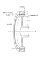
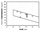
- FIG. 1 It is the schematic perspective view which illustrated the embodiment of the torsional damper of this invention. It is a schematic cross-sectional perspective view of the torsional damper shown in FIG. It is a schematic cross-sectional perspective view for demonstrating the manufacturing method of the torsional damper shown in FIG. It is the schematic cross-sectional perspective view of the torsional damper used for the resonance point tracking method. It is a graph which shows the example of the surface temperature of a rubber ring when the resonance point tracking method is performed. It is a graph which shows the relationship between the fitting width (mm) and the maximum temperature (Tmax) which reaches the surface of a rubber ring.
- the present invention has a hub that is fixed to a rotating shaft and has an outer peripheral surface on the circumference centered on the rotating shaft, and a diameter larger than the outer peripheral surface of the hub on the circumference centered on the rotating shaft.
- An annular vibrating ring having an inner peripheral surface and a rubber composition existing in a compressed state between the outer peripheral surface of the hub and the inner peripheral surface of the vibrating ring and containing EPDM as a main component, and having a surface temperature.
- a rubber ring having a loss coefficient (tan ⁇ ) of 0.18 or more when the temperature is 60 ⁇ 5 ° C.
- a torsional damper in which the maximum surface reaching temperature (Tmax) and the rubber fitting width (b) satisfy the formula (1): Tmax ⁇ -2.6b + 173.5 and the formula (2): 20 ⁇ b.
- Tmax maximum surface reaching temperature
- b rubber fitting width
- FIG. 1 is a schematic perspective view illustrating an embodiment of the torsional damper of the present invention
- FIG. 2 is a schematic cross-sectional perspective view of the torsional damper shown in FIG.
- the torsional damper 1 of the embodiment illustrated in FIGS. 1 and 2 can be used by being attached to the tip of the crankshaft of an engine of a vehicle or the like.
- the torsional damper 1 has a function of absorbing the torsional resonance of the crankshaft and suppressing engine vibration and noise. Further, it may also serve as a drive pulley (crank pulley) that transmits power to the auxiliary equipment via a belt for the rotation of the crankshaft.
- the torsional damper 1 has a hub 3, a vibrating ring 5, and a rubber ring 7.
- the hub 3 includes a boss portion 31, a stay portion 33, and a rim portion 35.
- the boss portion 31 is provided at the central portion in the radial direction of the hub 3.
- the boss portion 31 is fixed to the tip of the crankshaft (rotating shaft), and the hub 3 is rotationally driven around the rotating shaft X.
- the stay portion 33 extends radially from the boss portion 31.
- the rim portion 35 is provided on the outer peripheral side of the stay portion 33.
- the rim portion 35 has a cylindrical shape, and a vibrating ring 5 is connected to the outer peripheral side of the rim portion 35 via a rubber ring 7.
- the outer peripheral surface of the rim portion 35 exists on the circumference centered on the rotation axis X.
- each of the boss portion 31, the stay portion 33, and the rim portion 35 can be formed by using a metal material such as cast iron as a raw material. Further, each of the boss portion 31, the stay portion 33, and the rim portion 35 is preferably made of flake graphite cast iron, spheroidal graphite cast iron, hot-rolled steel sheet for automobile structure, or the like. Examples of flake graphite cast iron include FC100, FC150, FC200, FC250, FC300, FC350 and the like.
- Examples of spheroidal graphite cast iron are FCD350-22, FCD350-22L, FCD400-18, FCD400-18L, FCD400-15, FCD450-10, FCD500-7, FCD600-3, FCD700-2, FCD800-2, FCD400- 18A, FCD400-18AL, FCD400-15A, FCD500-7A, FCD600-3A, etc. can be mentioned.
- Examples of rolled steel sheets for automobile structures include SAPH310, SAPH370, SAPH410, SAPH440 and the like.
- the vibrating ring 5 is arranged on the outer side in the radial direction of the hub 3.
- the inner peripheral surface of the vibrating ring 5 has a larger diameter than the outer peripheral surface of the hub 3. This inner peripheral surface exists on the circumference centered on the crankshaft (rotating shaft X).
- a pulley groove 51 on which a belt is hung is provided on the outer peripheral surface of the vibrating ring 5.
- the pulley groove 51 functions as a pulley for power transmission.
- the vibrating ring 5 can be formed by using a metal material such as cast iron as a raw material. Further, the vibrating ring 5 is preferably made of flake graphite cast iron. This is because flake graphite cast iron has an excellent ability to absorb vibrations and also has excellent wear resistance. Examples of flake graphite cast iron include FC100, FC150, FC200, FC250, FC300, FC350 and the like.
- the rubber ring 7 is inserted in the gap between the outer peripheral surface of the hub 3 and the inner peripheral surface of the vibrating ring 5.
- the rubber ring 7 plays a role of reducing torsional vibration of the crankshaft generated during traveling of a vehicle or the like to prevent damage, and reducing noise and vibration of engine vibration.
- the rubber ring 7 is made by vulcanizing a rubber composition containing ethylene / propylene / diene ternary copolymer (EPDM) as a main component, preferably carbon black or process oil, into a cylindrical shape or the like by, for example, a conventionally known method. Can be obtained by doing.
- the rubber composition preferably contains EPDM in an amount of 10 to 60% by mass or more, more preferably 15 to 55% by mass, more preferably 20 to 50% by mass, and further containing 30 to 50% by mass. preferable.
- the amount of carbon black is preferably 40 to 130 parts by mass, more preferably 50 to 100 parts by mass, and further preferably 60 to 80 parts by mass with respect to 100 parts by mass of EPDM.
- the rubber composition may contain zinc oxide, stearic acid, an antiaging agent, a peroxide, a cross-linking agent and the like.
- the rubber ring 7 has a loss coefficient (tan ⁇ ) of 0.18 or more, preferably 0.18 to 0.40, and 0.19 to 0.35 when the surface temperature is 60 ⁇ 5 ° C. More preferably, it is more preferably 0.20 to 0.28.
- the loss coefficient (tan ⁇ ) when the surface temperature is 60 ⁇ 5 ° C. means a value obtained by measuring by a resonance point tracking method (natural frequency measurement) by a high-frequency vibration tester.
- the measurement by the resonance point tracking method shall be performed under the following conditions.
- the method for producing such a torsional damper of the present invention is not particularly limited.
- it can be manufactured by the following method.
- a hub 30 and a vibrating ring 50 as shown in FIG. 3 are prepared, and a torque improving liquid is applied thereto by means such as spraying.
- a torque improving liquid a solution in which a silane coupling agent is mainly dissolved in a hydrocarbon solution (solvent) such as toluene or xylene can be used.
- the torque improving liquid is preferably applied to the portion of the hub 30 and the vibrating ring 50 that comes into contact with the rubber ring 70, that is, the inner peripheral surface of the vibrating ring 50 and the outer peripheral surface of the rim portion of the hub 30.
- a rubber ring coated with the fitting liquid is press-fitted into the gap (gap portion 80) between the hub 30 and the vibrating ring 50 by using a press-fitting jig such as a press machine.
- the width of the gap in the gap 80 is narrower than the thickness of the rubber ring 70.
- the thickness of the rubber ring 70 / the width of the gap of the gap 80 is preferably about 0.6 to 0.9.
- the rubber ring exists in a compressed state between the outer peripheral surface of the hub and the inner peripheral surface of the vibrating ring.
- the present inventor has various structures with different wall thickness (a), fitting width (b), rubber thickness (c), fitting diameter (d), and hub fitting portion wall thickness (e).
- a damper was prepared and the effect on the temperature of the rubber ring was examined.
- the vibrating ring wall thickness (a) means the thickness of the vibrating ring 5 in the radial direction (direction perpendicular to the rotation axis X) as shown in FIG.
- the radial thickness of the vibrating ring 5 is measured at 10 randomly selected points. , The value obtained by averaging them is defined as the vibrating ring wall thickness (a).
- the fitting width (b) means the length of the rim portion 35 of the hub 3 in the rotation axis X direction.
- the fitting width (b) is not constant in the rotation axis X direction, the length of the longest portion of the rim portion 35 of the hub 3 in the rotation axis X direction is defined as the fitting width (b).
- the rubber thickness (c) means the thickness of the rubber ring 7 in the radial direction (direction perpendicular to the rotation axis X) as shown in FIG.
- the rubber thickness (c) is not constant in the radial direction of the rubber ring 7 as shown in FIG. 2, the thickness of the rubber ring 7 in the radial direction is measured at 10 randomly selected points, and these are measured. Let the value obtained by averaging the rubber thickness (c).
- the fitting diameter (d) means the diameter of the outer peripheral surface of the rim portion 35 in the hub 3. Further, the fitting diameter (d) means the shortest diameter among the diameters (outer diameters) of the outer peripheral surface of the rim portion 35. Therefore, as in the embodiment shown in FIG. 2, when the rim portion 35 is meandering with respect to the rotation axis X direction, the point closest to the rotation axis X on the outer peripheral surface thereof (in the case of FIG. 2, the rotation axis X). It shall mean the diameter at the center point in the direction).
- the hub fitting portion wall thickness (e) means the thickness of the rim portion 35 in the hub 3 in the radial direction (direction perpendicular to the rotation axis X).
- the hub fitting portion wall thickness (e) means a thickness other than the portion of the rim portion 35 that is connected to the stay portion 33.
- 10 is randomly selected in the direction perpendicular to the rotation axis X. At points, the thickness of the rim portion 35 in the radial direction (excluding the portion connected to the stay portion 33) is measured, and the value obtained by averaging them is taken as the hub fitting portion wall thickness (e).
- the present inventor has the embodiment shown in FIG. 4, in which the vibration ring wall thickness (a), the fitting width (b), the rubber thickness (c), the fitting diameter (d), and the hub fitting portion wall thickness (d).
- Tortional dampers having various structures with different e) were prepared, and each torsional damper was subjected to the above-mentioned resonance point tracking method, and the maximum surface temperature (Tmax) of the rubber ring at that time was measured.
- the maximum temperature (Tmax) reached on the surface of the rubber ring by the resonance point tracking method shall be measured under the following conditions.
- Vibration amplitude ⁇ 0.05 deg -Phase at vibration: -90 deg ⁇ Test time: Until the surface temperature of the rubber ring saturates ⁇ Atmospheric temperature: 23 ⁇ 3 °C -Rubber surface measurement method: Non-contact type surface thermometer
- the surface temperature of the rubber ring of the torsional damper was measured using a non-contact surface thermometer.
- An example of the measurement result is shown in FIG.
- the surface temperature of the rubber ring (vertical axis in FIG. 5) gradually rises from the start of the test and saturates after about 30 minutes have passed.
- the surface temperature of the rubber ring at the time of saturation was defined as the maximum temperature reached by the surface of the rubber ring (Tmax) in the torsional damper having the structure.
- the present inventor has different vibration ring wall thickness (a), fitting width (b), rubber thickness (c), fitting diameter (d), and hub fitting portion wall thickness (e).
- the torsional dampers having various structures were subjected to the resonance point tracking method, and the maximum temperature (Tmax) reached on the surface of the rubber ring at that time was measured. Then, it was found that the maximum temperature (Tmax) reached on the surface of the rubber ring strongly depends on the fitting width (b), and the temperature of the rubber ring does not rise in the region shown in FIG.
- the area can be expressed by an equation as follows. Equation (1): Tmax ⁇ -2.6b + 173.5 Equation (2): 20 ⁇ b
- the plot in FIG. 6 is data showing the relationship between the fitting width (b, unit is mm) actually measured by the above resonance point tracking method and the maximum temperature reached on the surface of the rubber ring (Tmax, unit is ° C.). Is.
- the data is shown in Table 1.
- the maximum surface temperature (Tmax) of the rubber ring is lower than 120 ° C.
- the rubber ring used in the present invention is a rubber ring composed of a rubber composition containing EPDM as a main component and having a loss coefficient (tan ⁇ ) of 0.18 or more when the surface temperature is 60 ⁇ 5 ° C. Such a rubber ring is not easily damaged when the maximum surface temperature (Tmax) is 120 ° C. or lower.
- the torsional damper of the present invention preferably satisfies the formula (3).
- the fitting width (b) is 20 mm or more as compared with the formula (2), but more preferably 25 mm or more.
- the fitting width (b) is preferably 100 mm or less, more preferably 80 mm or less, more preferably 60 mm or less, more preferably 40 mm or less, and more preferably 35 mm or less. More preferred.
- the rubber ring is extremely unlikely to be damaged due to heat generation.
- a proposal for example, the torsional damper described in Patent Document 1 to suppress heat generation of a rubber ring by adjusting the material of the rubber ring.
- the heat generation of the rubber ring is suppressed by adjusting the structure of the torsional damper, specifically, the length (fitting width) of the vibrating ring in the rotation axis X direction.
- the idea did not exist. It can be said that the present invention is not an invention that can be easily conceived by those skilled in the art in that the technical idea is shown and the region where the heat generation of the rubber ring can be suppressed is shown by a concrete mathematical formula. ..
Landscapes
- Engineering & Computer Science (AREA)
- General Engineering & Computer Science (AREA)
- Mechanical Engineering (AREA)
- Physics & Mathematics (AREA)
- Acoustics & Sound (AREA)
- Aviation & Aerospace Engineering (AREA)
- Pulleys (AREA)
Priority Applications (5)
| Application Number | Priority Date | Filing Date | Title |
|---|---|---|---|
| JP2021565412A JP7318000B2 (ja) | 2019-12-20 | 2020-11-25 | トーショナルダンパ |
| KR1020227016063A KR102802056B1 (ko) | 2019-12-20 | 2020-11-25 | 토셔널 댐퍼 |
| US17/779,609 US20230003278A1 (en) | 2019-12-20 | 2020-11-25 | Torsional damper |
| CN202080073439.0A CN114599896B (zh) | 2019-12-20 | 2020-11-25 | 扭转减振器 |
| EP20902888.5A EP4080083A4 (en) | 2019-12-20 | 2020-11-25 | TORSION DAMPER |
Applications Claiming Priority (2)
| Application Number | Priority Date | Filing Date | Title |
|---|---|---|---|
| JP2019-230165 | 2019-12-20 | ||
| JP2019230165 | 2019-12-20 |
Publications (1)
| Publication Number | Publication Date |
|---|---|
| WO2021124818A1 true WO2021124818A1 (ja) | 2021-06-24 |
Family
ID=76477518
Family Applications (1)
| Application Number | Title | Priority Date | Filing Date |
|---|---|---|---|
| PCT/JP2020/043857 Ceased WO2021124818A1 (ja) | 2019-12-20 | 2020-11-25 | トーショナルダンパ |
Country Status (6)
| Country | Link |
|---|---|
| US (1) | US20230003278A1 (https=) |
| EP (1) | EP4080083A4 (https=) |
| JP (1) | JP7318000B2 (https=) |
| KR (1) | KR102802056B1 (https=) |
| CN (1) | CN114599896B (https=) |
| WO (1) | WO2021124818A1 (https=) |
Families Citing this family (1)
| Publication number | Priority date | Publication date | Assignee | Title |
|---|---|---|---|---|
| CN114616409B (zh) * | 2019-12-20 | 2024-11-26 | Nok株式会社 | 扭转减振器 |
Citations (2)
| Publication number | Priority date | Publication date | Assignee | Title |
|---|---|---|---|---|
| JP2007009073A (ja) * | 2005-06-30 | 2007-01-18 | Nissin Kogyo Co Ltd | ダンパー用ゴム部材 |
| JP2018096455A (ja) | 2016-12-13 | 2018-06-21 | 株式会社フコク | トーショナルダンパ |
Family Cites Families (24)
| Publication number | Priority date | Publication date | Assignee | Title |
|---|---|---|---|---|
| JPH08219233A (ja) * | 1995-02-17 | 1996-08-27 | Nok Megurasutikku Kk | ダンパ |
| JPH11159576A (ja) * | 1997-11-28 | 1999-06-15 | Nok Megurasutikku Kk | ダンパ |
| JPH11210832A (ja) * | 1998-01-27 | 1999-08-03 | Mitsubishi Motors Corp | ラバーダンパ装置 |
| JP4556281B2 (ja) | 1999-06-23 | 2010-10-06 | 株式会社ブリヂストン | 防振ゴム組成物 |
| DE60000642T2 (de) * | 1999-08-27 | 2003-07-31 | Toyo Tire & Rubber Co., Ltd. | Riemenscheibe mit Dämpfungselement |
| JP3766928B2 (ja) | 2001-03-23 | 2006-04-19 | 東洋ゴム工業株式会社 | ビスカスラバーダンパ |
| JP4329788B2 (ja) * | 2006-07-18 | 2009-09-09 | トヨタ自動車株式会社 | エンジンの回転バランス調整方法 |
| US7834090B2 (en) * | 2007-08-03 | 2010-11-16 | The Gates Corporation | Rubber composition and vibration damper using the rubber composition |
| WO2015012018A1 (ja) * | 2013-07-25 | 2015-01-29 | Nok株式会社 | トーショナルダンパー用epdm組成物 |
| US20170059028A1 (en) * | 2015-08-27 | 2017-03-02 | Dayco Ip Holdings, Llc | Torsional vibration dampers having a hub with spokes acting as a second spring in series with an elastomeric member |
| JP2018040393A (ja) * | 2016-09-06 | 2018-03-15 | Nok株式会社 | トーショナルダンパ |
| JP2018071703A (ja) * | 2016-10-31 | 2018-05-10 | 株式会社フコク | ダンパゴム部材およびトーショナルダンパ |
| JP2018115666A (ja) * | 2017-01-16 | 2018-07-26 | Nok株式会社 | トーショナルダンパ |
| JP6817539B2 (ja) * | 2017-02-15 | 2021-01-20 | トヨタ自動車株式会社 | トーショナルダンパ |
| JP6540907B2 (ja) * | 2017-04-21 | 2019-07-10 | Nok株式会社 | トーショナルダンパー用ゴム組成物及びトーショナルダンパー |
| JP6882067B2 (ja) * | 2017-05-23 | 2021-06-02 | 株式会社フコク | トーショナルダンパ |
| JP7021963B2 (ja) * | 2018-01-30 | 2022-02-17 | 株式会社フコク | ゴム部材およびそれを用いたダンパー |
| JP7057684B2 (ja) * | 2018-02-28 | 2022-04-20 | 株式会社フコク | ゴム部材およびそれを用いたダンパー |
| CN117050435A (zh) * | 2019-07-08 | 2023-11-14 | Nok株式会社 | 扭振减振器用橡胶组合物 |
| JP7390871B2 (ja) * | 2019-11-20 | 2023-12-04 | Nok株式会社 | トーショナルダンパおよびその製造方法 |
| JP7377696B2 (ja) * | 2019-12-20 | 2023-11-10 | Nok株式会社 | トーショナルダンパ |
| US11920652B2 (en) * | 2019-12-20 | 2024-03-05 | Nok Corporation | Torsional damper |
| JP7318001B2 (ja) * | 2019-12-20 | 2023-07-31 | Nok株式会社 | トーショナルダンパ |
| CN114616409B (zh) * | 2019-12-20 | 2024-11-26 | Nok株式会社 | 扭转减振器 |
-
2020
- 2020-11-25 KR KR1020227016063A patent/KR102802056B1/ko active Active
- 2020-11-25 JP JP2021565412A patent/JP7318000B2/ja active Active
- 2020-11-25 WO PCT/JP2020/043857 patent/WO2021124818A1/ja not_active Ceased
- 2020-11-25 CN CN202080073439.0A patent/CN114599896B/zh active Active
- 2020-11-25 US US17/779,609 patent/US20230003278A1/en not_active Abandoned
- 2020-11-25 EP EP20902888.5A patent/EP4080083A4/en active Pending
Patent Citations (2)
| Publication number | Priority date | Publication date | Assignee | Title |
|---|---|---|---|---|
| JP2007009073A (ja) * | 2005-06-30 | 2007-01-18 | Nissin Kogyo Co Ltd | ダンパー用ゴム部材 |
| JP2018096455A (ja) | 2016-12-13 | 2018-06-21 | 株式会社フコク | トーショナルダンパ |
Non-Patent Citations (1)
| Title |
|---|
| See also references of EP4080083A4 |
Also Published As
| Publication number | Publication date |
|---|---|
| EP4080083A4 (en) | 2024-01-24 |
| CN114599896B (zh) | 2024-11-26 |
| JP7318000B2 (ja) | 2023-07-31 |
| CN114599896A (zh) | 2022-06-07 |
| KR20220075429A (ko) | 2022-06-08 |
| JPWO2021124818A1 (https=) | 2021-06-24 |
| KR102802056B1 (ko) | 2025-05-02 |
| US20230003278A1 (en) | 2023-01-05 |
| EP4080083A1 (en) | 2022-10-26 |
Similar Documents
| Publication | Publication Date | Title |
|---|---|---|
| JP7318003B2 (ja) | トーショナルダンパ | |
| JP7318001B2 (ja) | トーショナルダンパ | |
| JP7377696B2 (ja) | トーショナルダンパ | |
| CN110678669A (zh) | 扭转减振器 | |
| WO2021124818A1 (ja) | トーショナルダンパ | |
| JP7318002B2 (ja) | トーショナルダンパ | |
| WO2018109994A1 (ja) | トーショナルダンパ | |
| JP2021081017A (ja) | トーショナルダンパおよびその製造方法 | |
| JP7496301B2 (ja) | トルク変動吸収ダンパー | |
| JP7542479B2 (ja) | トーショナルダンパ | |
| JP7550318B2 (ja) | トーショナルダンパおよびそれを得るために用いる塗料 | |
| JP2021196031A (ja) | トーショナルダンパおよびその製造方法 | |
| JP2002357244A (ja) | トーショナルダンパ | |
| JP2005009551A (ja) | トーショナルダンパ |
Legal Events
| Date | Code | Title | Description |
|---|---|---|---|
| 121 | Ep: the epo has been informed by wipo that ep was designated in this application |
Ref document number: 20902888 Country of ref document: EP Kind code of ref document: A1 |
|
| DPE2 | Request for preliminary examination filed before expiration of 19th month from priority date (pct application filed from 20040101) | ||
| ENP | Entry into the national phase |
Ref document number: 2021565412 Country of ref document: JP Kind code of ref document: A |
|
| ENP | Entry into the national phase |
Ref document number: 20227016063 Country of ref document: KR Kind code of ref document: A |
|
| NENP | Non-entry into the national phase |
Ref country code: DE |
|
| ENP | Entry into the national phase |
Ref document number: 2020902888 Country of ref document: EP Effective date: 20220720 |