WO2021124487A1 - インナーロータ型電動機、送風装置及びインナーロータ型電動機の製造方法 - Google Patents
インナーロータ型電動機、送風装置及びインナーロータ型電動機の製造方法 Download PDFInfo
- Publication number
- WO2021124487A1 WO2021124487A1 PCT/JP2019/049656 JP2019049656W WO2021124487A1 WO 2021124487 A1 WO2021124487 A1 WO 2021124487A1 JP 2019049656 W JP2019049656 W JP 2019049656W WO 2021124487 A1 WO2021124487 A1 WO 2021124487A1
- Authority
- WO
- WIPO (PCT)
- Prior art keywords
- teeth
- type motor
- inner rotor
- rotor type
- stator
- Prior art date
- Legal status (The legal status is an assumption and is not a legal conclusion. Google has not performed a legal analysis and makes no representation as to the accuracy of the status listed.)
- Ceased
Links
Images







Classifications
-
- H—ELECTRICITY
- H02—GENERATION; CONVERSION OR DISTRIBUTION OF ELECTRIC POWER
- H02K—DYNAMO-ELECTRIC MACHINES
- H02K1/00—Details of the magnetic circuit
- H02K1/06—Details of the magnetic circuit characterised by the shape, form or construction
- H02K1/08—Salient poles
-
- H—ELECTRICITY
- H02—GENERATION; CONVERSION OR DISTRIBUTION OF ELECTRIC POWER
- H02K—DYNAMO-ELECTRIC MACHINES
- H02K3/00—Details of windings
- H02K3/04—Windings characterised by the conductor shape, form or construction, e.g. with bar conductors
- H02K3/18—Windings for salient poles
Definitions
- the present disclosure relates to an inner rotor type motor in which a rotor is arranged on the inner peripheral side of an annular stator, a blower equipped with the rotor, and a method for manufacturing the inner rotor type motor.
- the rotor In the inner rotor type motor, the rotor is placed on the inner peripheral side of the annular stator.
- the stator has an annular core back portion, a stator core having a plurality of teeth portions protruding inward from the core back portion, and a coil wound around the teeth portion.
- the teeth portions are arranged radially so that each center line passes through the center point of the ring of the core back portion.
- Patent Document 1 discloses a motor which is an inner rotor type motor in which the coil end of a distributed winding coil is suppressed low by dividing the stator core into a teeth portion and a core back portion.
- a pre-coiled winding coil is placed in a slot between the teeth portions in a post-insertion manner from the core back portion side, so that the coil is wound around the teeth portions in a distributed winding manner. Forming a stator.
- the slot pitch becomes wider toward the core back side. Therefore, in the motor disclosed in Patent Document 1, the coil cannot be post-inserted into the slot unless the coil has a circumference longer than the circumference of the slot. Therefore, in the motor disclosed in Patent Document 1, it is not possible to arrange a coil having a peripheral length shorter than the peripheral length of the slot in a state where a plurality of teeth portions are arranged radially in the slot. Therefore, the coil arranged in the slot has a surplus in the peripheral length, and the coil end in the state where the coil is inserted in the slot becomes large.
- the present disclosure has been made in view of the above, and an object of the present disclosure is to obtain an inner rotor type motor having a miniaturized coil end.
- the inner rotor type motor according to the present disclosure is fixed with an annular core back portion and a plurality of teeth portions protruding from the core back portion to the inner peripheral side.
- Leave a gap between the stator and the stator which has a rotor core and a distributed winding coil arranged in a slot between each of the plurality of teeth portions and wound around two or more of the plurality of teeth portions. It has a rotor that is rotatably supported on the inner peripheral side of the stator.
- the center line of each of the plurality of teeth portions circumscribes a common circle centered on the center point of the core back portion.
- the circumference of the coil is shorter than the circumference of the slot when each of the teeth is arranged radially.
- the inner rotor type motor according to the present disclosure has the effect of being able to miniaturize the coil end.
- FIG. 1 An exploded perspective view of the inner rotor type motor according to the first embodiment.
- Circuit diagram of the inner rotor type motor according to the first embodiment Perspective view of the rotor of the inner rotor type motor according to the first embodiment.
- FIG. 1 is an exploded perspective view of the inner rotor type motor according to the first embodiment.
- the inner rotor type motor 100 holds an annular stator 1, a rotor 2 arranged on the inner peripheral side of the stator 1, bearings 3a and 3b that rotatably support the rotor 2, and a bearing 3a. It has a frame 4 and a bracket 5 for holding the bearing 3b.
- the stator 1 and the rotor 2 are housed in the inner space of the outer shell formed by the frame 4 and the bracket 5.
- the bearings 3a and 3b rotatably support the shaft 104 of the rotor 2.
- FIG. 2 is a perspective view of the stator core of the inner rotor type motor according to the first embodiment.
- FIG. 3 is an exploded perspective view of the stator core of the inner rotor type motor according to the first embodiment.
- the stator 1 has an annular core back portion 8 and a stator core 6 having a teeth portion 7 protruding inward from the core back portion 8.
- the stator core 6 is formed by laminating a plurality of electromagnetic steel sheets, which are magnetic materials, in the axial direction of the shaft 104.
- Each of the teeth portions 7 is arranged on the inner peripheral side of the core back portion 8 at intervals in the circumferential direction.
- the stator core 6 has eight teeth portions 7.
- the stator 1 has a winding 9 having a coil wound around the teeth portion 7 and an insulator 10 that insulates the stator core 6 and the winding 9.
- the stator 1 has two phases and four poles and includes eight coils.
- the stator 1 contains two distributed winding coils for each slot between the teeth portions 7.
- the stator 1 is fitted on the inner peripheral surface of the frame 4.
- the stator 1 and the rotor 2 are arranged coaxially, and the rotor 2 is rotatable on the inner peripheral side of the stator core 6.
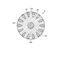
- FIG. 4 is a cross-sectional view of the stator of the inner rotor type motor according to the first embodiment.
- the teeth portion 7 is a portion that faces the rotor 2 and the slot forming portion 78 that forms a slot between the connecting portion 77 that engages with the core back portion 8 and the adjacent teeth portion 7. It has a peripheral portion 79. As shown in FIG. 4, each center line of the teeth portion 7 is a midpoint D in the circumferential direction of the inner peripheral portion 79 and a midpoint in the circumferential direction at the end of the slot forming portion 78 on the core back portion 8 side. Pass through with E.
- Each center line of the teeth portion 7 has an inclination of an angle ⁇ with respect to a line segment connecting the midpoint D in the circumferential direction of the inner peripheral portion 79 and the center point C of the core back portion 8.
- Each center line of the teeth portion 7 is inclined in the same direction in the circumferential direction from the line connecting the midpoint D in the circumferential direction of the inner peripheral portion 79 and the center point C of the core back portion 8.
- each center line of the teeth portion 7 is deviated in the clockwise direction from the line connecting the midpoint of the inner peripheral portion 79 in the circumferential direction and the center point C of the core back portion 8.
- each center line of the teeth portion 7 circumscribes a common circle centered on the center point C of the core back portion 8. As described above, since the center lines of the teeth portions 7 do not pass through a common point, the teeth portions 7 are not arranged radially in the inner rotor type motor 100 according to the first embodiment.
- the connecting portion 77 has a distance g from the line connecting the midpoint D in the circumferential direction of the inner peripheral portion 79 and the center point C in the core back portion 8 to the same side as the center line of the teeth portion 7 inclines in the circumferential direction. They are misaligned.
- the winding 9 has four main winding coil portions 109a, 109b, 109c, 109d and four auxiliary winding coil portions 110a, 110b, 110c, 110d.
- the four main winding coil portions 109a, 109b, 109c, 109d are connected in series with each other to form the main winding 109.
- the four auxiliary winding coil portions 110a, 110b, 110c, 110d are connected in series with each other to form the auxiliary winding 110.
- the main winding 109 and the auxiliary winding 110 are connected to form the winding 9.
- a rotating magnetic field is generated in the stator 1 by energizing the main winding 109 and the auxiliary winding 110.
- the rotor 2 receives a rotating magnetic field generated by the stator 1 and rotates about the central axis of the shaft 104.
- FIG. 5 is a circuit diagram of the inner rotor type motor according to the first embodiment.
- the series body in which the auxiliary winding 110 composed of the four auxiliary winding coil portions 110a, 110b, 110c, 110d shown in FIG. 4 and the capacitor 128 are connected in series is the four main winding coils shown in FIG.
- the main winding 109 including the parts 109a, 109b, 109c, and 109d and the single-phase AC power supply 127 are connected in parallel, respectively.
- auxiliary winding current Is flowing in the auxiliary winding 110 is about 90 ° ahead of the main winding current Im flowing in the main winding 109 by the capacitor 128.
- a rotating magnetic field is generated in the stator 1 along the rotation direction of the rotor 2.
- An ideal rotating magnetic field is obtained when the phase of the auxiliary winding current Is is advanced by 90 ° with respect to the main winding current Im.
- FIG. 6 is a perspective view of the rotor of the inner rotor type motor according to the first embodiment.
- the rotor 2 includes a tubular rotor core 129, a plurality of conductor rods 130 arranged at equal intervals in the circumferential direction on the outer peripheral surface side of the rotor core 129, and a plurality of conductor rods 130 of the rotor core 129. It has a short-circuit ring 131 for short-circuiting at both ends in the axial direction.
- the short-circuit ring 131 is made of a conductor such as aluminum or copper, and each conductor rod 130 is short-circuited at both ends in the axial direction of the rotor 2.
- the conductor rod 130 is made of a conductor such as aluminum or copper, and is inserted into the groove portion 141 of the rotor core 129. Further, the conductor rod 130 has a constant angle with respect to the rotation axis.
- the conductor rod 130 and the short-circuit ring 131 may be manufactured by a die-casting method in which molten metal is poured into the groove portion 141 of the rotor core 129 and both ends in the axial direction. Further, a metal rod may be inserted into the groove portion 141 of the adjacent rotor cores 129, and both ends of the metal rod may be soldered or brazed to the metal short-circuit ring 131. Further, in order to reduce the resistance of the conductor rod 130, a metal rod having a low resistivity such as a copper rod is inserted into the groove portion 141 of the rotor core 129, and then the conductor rod 130 and the short-circuit ring 131 are created by die casting. May be done.
- FIG. 7 is a cross-sectional view of the rotor of the inner rotor type motor according to the first embodiment.
- the rotor core 129 is formed by laminating a plurality of electromagnetic steel sheets made of a magnetic material in the direction of the rotation axis of the shaft 104. Further, the rotor core 129 protrudes radially outward from the annular back yoke portion 132 fitted to the outer peripheral surface of the shaft 104 and the back yoke portion 132, respectively, and is spaced apart from each other in the circumferential direction of the rotor core 129. It has a plurality of rotor teeth portions 133 arranged in the same manner. The rotor teeth portions 133 are arranged at equal intervals in the circumferential direction of the rotor core 129.
- FIG. 8 is a diagram showing how to arrange the windings of the inner rotor type motor according to the first embodiment. Since each center line of the teeth portion 7 circumscribes a common circle centered on the center point of the core back portion 8, the slot pitch L2 is such that the teeth portions 7 are arranged radially and the center of each teeth portion 7. The line is shorter than the slot pitch L1 when the line passes through the center point C of the core back portion 8. Therefore, a coil having a circumference shorter than the circumference of the slot on the core back portion 8 side of the teeth portion 7 arranged radially can be arranged in the slot. The circumference of the slot can be defined as the axial length of the tooth portion 7 and twice the sum of the slot pitch.
- the circumference of the coil can be defined as the length in the circumference direction on the inner diameter side of the coil. Further, since the connecting portion 77 is arranged on the same side as the direction in which the center line of the teeth portion 7 deviates from the line connecting the midpoint of the inner peripheral portion 79 in the circumferential direction and the center point C of the core back portion 8. , The slot pitch L2 can be further reduced.
- the inner rotor type motor 100 since the coils are distributed windings, one side of the coils is first inserted into all the slots, and all the coils are tilted in the same direction to arrange the coils in the slots. ..
- FIG. 9 is a diagram showing how to wind the coil of the inner rotor type motor according to the first embodiment.
- the main winding coil portion 109a is wound so as to surround the teeth portion 7a and the teeth portion 7b of the teeth portions 7a, 7b, 7c, 7d, 7e, 7f, 7g, and 7h.
- the auxiliary winding coil portion 110a adjacent to the main winding coil portion 109a in the counterclockwise direction includes the teeth portion 7b and the teeth portion 7c of the teeth portions 7a, 7b, 7c, 7d, 7e, 7f, 7g, and 7h. Wrapped around.
- the main winding coil portion 109b adjacent to the auxiliary winding coil portion 110a in the counterclockwise direction includes the teeth portion 7c and the teeth portion 7d among the teeth portions 7a, 7b, 7c, 7d, 7e, 7f, 7g, and 7h. Wrapped around.
- the auxiliary winding coil portion 110b, the main winding coil portion 109c, the auxiliary winding coil portion 110c, the main winding coil portion 109d, and the auxiliary winding coil portion 110d are wound in the same manner.
- the main winding coil portion 109a and the main winding coil portion 109b are arranged between the teeth portion 7b and the teeth portion 7c, the main winding coil portion 109b is arranged on the inner peripheral side, and the main winding coil portion 109a is on the outer periphery. It is wound so that it is placed on the side. That is, the main winding coil portions 109a, 109b, 109c, 109d and the auxiliary winding coil portions 110a, 110b, 110c, 110d are adjacent to each other in the circumferential direction, and the one in the clockwise direction is the inner peripheral side and the left. The coil is wound over the two tooth portions 7 so that the one in the clockwise direction is arranged on the outer peripheral side.
- each tooth portion 7 is tilted in the clockwise direction, and the outer peripheral side is moved in the clockwise direction. Therefore, the main winding coil portions 109a, 109b, 109c, 109d or the auxiliary winding coil portion 110a , 110b, 110c, 110d
- the teeth portion 7 is the main winding coil portion 109a, 109b, 109c, 109d.
- the distance between the tooth portions 7 becomes narrower toward the center side of the auxiliary winding coil portions 110a, 110b, 110c, 110d.
- the inner rotor type motor according to the first embodiment can be assembled without providing extra lengths in the main winding coil portions 109a, 109b, 109c, 109d and the auxiliary winding coil portions 110a, 110b, 110c, 110d. Can be done.
- FIG. 10 is a diagram showing a state in which the main winding coil portion and the auxiliary winding coil portion are arranged in a distributed winding in the slot of the inner rotor type motor according to the first embodiment. Finally, by assembling the core back portion 8 to the teeth portion 7, the stator 1 having the distributed winding coil is completed.
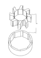
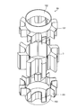
- FIG. 11 is an exploded perspective view of the insulator of the inner rotor type motor according to the first embodiment.
- FIG. 12 is a diagram showing a state in which an insulator is assembled to the teeth portion of the inner rotor type motor according to the first embodiment.
- the insulator 10 is arranged in a mounting portion 101 mounted on each of the plurality of teeth portions 7 and a portion in which the inner peripheral surface of the teeth portion 7 extends in the direction of the rotation axis of the rotor 2, and the insulator 10 is arranged in a portion of the plurality of teeth portions 7.
- a wall portion 102 that connects all the portions to be attached to each is provided.
- the insulator 10 can insulate the coil and the rotor 2 on the entire circumference. Further, since the position of each tooth portion 7 is determined by the insulator 10, the core back portion 8 can be easily press-fitted.
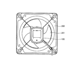
- FIG. 13 is a diagram showing a configuration of a blower using an inner rotor type motor according to the first embodiment.
- the ventilation fan 200 which is a blower, includes an inner rotor type electric motor 100 and a fan 201 attached to the shaft 104. A ventilation flow is formed by the inner rotor type motor 100 rotating the fan 201 through the shaft 104.
- the ventilation fan 200 is given as an example of the blower here, the blower to which the inner rotor type electric motor 100 is applied may be a fan.
- the teeth portions 7 in which the peripheral lengths of the main winding coil portions 109a, 109b, 109c, 109d and the auxiliary winding coil portions 110a, 110b, 110c, 110d are radially arranged Since it can be made shorter than the circumference of the slot on the core back portion 8 side of the above, the coil end can be made smaller and the motor efficiency can be improved.
- the configuration shown in the above embodiments is an example, and can be combined with another known technique, can be combined with each other, and does not deviate from the gist. It is also possible to omit or change a part of the configuration.
Landscapes
- Engineering & Computer Science (AREA)
- Power Engineering (AREA)
- Iron Core Of Rotating Electric Machines (AREA)
- Windings For Motors And Generators (AREA)
- Manufacture Of Motors, Generators (AREA)
Priority Applications (2)
| Application Number | Priority Date | Filing Date | Title |
|---|---|---|---|
| JP2021565239A JP7313476B2 (ja) | 2019-12-18 | 2019-12-18 | インナーロータ型電動機、送風装置及びインナーロータ型電動機の製造方法 |
| PCT/JP2019/049656 WO2021124487A1 (ja) | 2019-12-18 | 2019-12-18 | インナーロータ型電動機、送風装置及びインナーロータ型電動機の製造方法 |
Applications Claiming Priority (1)
| Application Number | Priority Date | Filing Date | Title |
|---|---|---|---|
| PCT/JP2019/049656 WO2021124487A1 (ja) | 2019-12-18 | 2019-12-18 | インナーロータ型電動機、送風装置及びインナーロータ型電動機の製造方法 |
Publications (1)
| Publication Number | Publication Date |
|---|---|
| WO2021124487A1 true WO2021124487A1 (ja) | 2021-06-24 |
Family
ID=76477430
Family Applications (1)
| Application Number | Title | Priority Date | Filing Date |
|---|---|---|---|
| PCT/JP2019/049656 Ceased WO2021124487A1 (ja) | 2019-12-18 | 2019-12-18 | インナーロータ型電動機、送風装置及びインナーロータ型電動機の製造方法 |
Country Status (2)
| Country | Link |
|---|---|
| JP (1) | JP7313476B2 (https=) |
| WO (1) | WO2021124487A1 (https=) |
Citations (7)
| Publication number | Priority date | Publication date | Assignee | Title |
|---|---|---|---|---|
| JP2000184632A (ja) * | 1998-12-09 | 2000-06-30 | Denso Corp | 回転電機及びその製造方法 |
| JP2000209821A (ja) * | 1999-01-12 | 2000-07-28 | Honda Motor Co Ltd | 電動機の製造装置 |
| JP2001346366A (ja) * | 2000-03-27 | 2001-12-14 | Matsushita Electric Ind Co Ltd | 電動機およびその製造方法ならびにそれを用いたコンプレッサー |
| JP2003324926A (ja) * | 2002-04-30 | 2003-11-14 | Seiko Epson Corp | 電機子、及び該電機子を備えたdcモータ |
| JP2005204476A (ja) * | 2004-01-19 | 2005-07-28 | Mitsui High Tec Inc | 分割積層固定子鉄心 |
| JP2015080341A (ja) * | 2013-10-17 | 2015-04-23 | ミネベア株式会社 | インシュレータ、及びそれを備えるステータ、及びそれを備えるモータ |
| JP2019092355A (ja) * | 2017-11-17 | 2019-06-13 | 株式会社ジェイテクト | モータ用ステータ |
-
2019
- 2019-12-18 JP JP2021565239A patent/JP7313476B2/ja active Active
- 2019-12-18 WO PCT/JP2019/049656 patent/WO2021124487A1/ja not_active Ceased
Patent Citations (7)
| Publication number | Priority date | Publication date | Assignee | Title |
|---|---|---|---|---|
| JP2000184632A (ja) * | 1998-12-09 | 2000-06-30 | Denso Corp | 回転電機及びその製造方法 |
| JP2000209821A (ja) * | 1999-01-12 | 2000-07-28 | Honda Motor Co Ltd | 電動機の製造装置 |
| JP2001346366A (ja) * | 2000-03-27 | 2001-12-14 | Matsushita Electric Ind Co Ltd | 電動機およびその製造方法ならびにそれを用いたコンプレッサー |
| JP2003324926A (ja) * | 2002-04-30 | 2003-11-14 | Seiko Epson Corp | 電機子、及び該電機子を備えたdcモータ |
| JP2005204476A (ja) * | 2004-01-19 | 2005-07-28 | Mitsui High Tec Inc | 分割積層固定子鉄心 |
| JP2015080341A (ja) * | 2013-10-17 | 2015-04-23 | ミネベア株式会社 | インシュレータ、及びそれを備えるステータ、及びそれを備えるモータ |
| JP2019092355A (ja) * | 2017-11-17 | 2019-06-13 | 株式会社ジェイテクト | モータ用ステータ |
Also Published As
| Publication number | Publication date |
|---|---|
| JPWO2021124487A1 (https=) | 2021-06-24 |
| JP7313476B2 (ja) | 2023-07-24 |
Similar Documents
| Publication | Publication Date | Title |
|---|---|---|
| US7652402B2 (en) | Brushless motor | |
| US20020171306A1 (en) | Brushless motor | |
| JP5824644B2 (ja) | 直流モータ | |
| JP2000166131A (ja) | モ―タ或いは発電機用のステ―タ | |
| US6057621A (en) | Cylindrical radial gap type motor structure | |
| JP2018166353A (ja) | 電動モータ | |
| JP6946209B2 (ja) | レゾルバのステータ構造およびレゾルバ | |
| US20180175694A1 (en) | Electric Motor And Stator Thereof | |
| CN1147716A (zh) | 小型电动机 | |
| JP2004056932A (ja) | 外転型モータ | |
| US10644547B2 (en) | Armature | |
| JP2008079471A (ja) | ファンシステム,電動機及びクローポール型モータ | |
| WO2015104795A1 (ja) | 回転電機 | |
| CN114846728A (zh) | 线圈以及具备该线圈的定子、马达 | |
| JP2020171072A (ja) | 回転電機 | |
| CN114830503B (zh) | 具有紧凑的汇流排单元的电动机 | |
| WO2021124487A1 (ja) | インナーロータ型電動機、送風装置及びインナーロータ型電動機の製造方法 | |
| JP7297097B2 (ja) | インナーロータ型電動機の製造方法 | |
| JP6545381B2 (ja) | 回転電機の固定子 | |
| CN113892226A (zh) | 电机 | |
| JP2006271142A (ja) | 回転機 | |
| TW201926856A (zh) | 無槽式電動機、以及使用其之電動送風機或電動吸塵器 | |
| PL232584B1 (pl) | Urządzenie elektryczne i układ do sterowania | |
| JP2012010537A (ja) | クローポール型天井扇風機モータ | |
| JP2004007910A (ja) | 誘導電動機 |
Legal Events
| Date | Code | Title | Description |
|---|---|---|---|
| 121 | Ep: the epo has been informed by wipo that ep was designated in this application |
Ref document number: 19956187 Country of ref document: EP Kind code of ref document: A1 |
|
| ENP | Entry into the national phase |
Ref document number: 2021565239 Country of ref document: JP Kind code of ref document: A |
|
| NENP | Non-entry into the national phase |
Ref country code: DE |
|
| 122 | Ep: pct application non-entry in european phase |
Ref document number: 19956187 Country of ref document: EP Kind code of ref document: A1 |