WO2021124487A1 - Inner rotor-type motor, blowing device, and method for manufacturing inner rotor-type motor - Google Patents
Inner rotor-type motor, blowing device, and method for manufacturing inner rotor-type motor Download PDFInfo
- Publication number
- WO2021124487A1 WO2021124487A1 PCT/JP2019/049656 JP2019049656W WO2021124487A1 WO 2021124487 A1 WO2021124487 A1 WO 2021124487A1 JP 2019049656 W JP2019049656 W JP 2019049656W WO 2021124487 A1 WO2021124487 A1 WO 2021124487A1
- Authority
- WO
- WIPO (PCT)
- Prior art keywords
- teeth
- type motor
- inner rotor
- rotor type
- stator
- Prior art date
Links
Images


Classifications
-
- H—ELECTRICITY
- H02—GENERATION; CONVERSION OR DISTRIBUTION OF ELECTRIC POWER
- H02K—DYNAMO-ELECTRIC MACHINES
- H02K1/00—Details of the magnetic circuit
- H02K1/06—Details of the magnetic circuit characterised by the shape, form or construction
- H02K1/08—Salient poles
-
- H—ELECTRICITY
- H02—GENERATION; CONVERSION OR DISTRIBUTION OF ELECTRIC POWER
- H02K—DYNAMO-ELECTRIC MACHINES
- H02K3/00—Details of windings
- H02K3/04—Windings characterised by the conductor shape, form or construction, e.g. with bar conductors
- H02K3/18—Windings for salient poles
Definitions
- the present disclosure relates to an inner rotor type motor in which a rotor is arranged on the inner peripheral side of an annular stator, a blower equipped with the rotor, and a method for manufacturing the inner rotor type motor.
- the rotor In the inner rotor type motor, the rotor is placed on the inner peripheral side of the annular stator.
- the stator has an annular core back portion, a stator core having a plurality of teeth portions protruding inward from the core back portion, and a coil wound around the teeth portion.
- the teeth portions are arranged radially so that each center line passes through the center point of the ring of the core back portion.
- Patent Document 1 discloses a motor which is an inner rotor type motor in which the coil end of a distributed winding coil is suppressed low by dividing the stator core into a teeth portion and a core back portion.
- a pre-coiled winding coil is placed in a slot between the teeth portions in a post-insertion manner from the core back portion side, so that the coil is wound around the teeth portions in a distributed winding manner. Forming a stator.
- the slot pitch becomes wider toward the core back side. Therefore, in the motor disclosed in Patent Document 1, the coil cannot be post-inserted into the slot unless the coil has a circumference longer than the circumference of the slot. Therefore, in the motor disclosed in Patent Document 1, it is not possible to arrange a coil having a peripheral length shorter than the peripheral length of the slot in a state where a plurality of teeth portions are arranged radially in the slot. Therefore, the coil arranged in the slot has a surplus in the peripheral length, and the coil end in the state where the coil is inserted in the slot becomes large.
- the present disclosure has been made in view of the above, and an object of the present disclosure is to obtain an inner rotor type motor having a miniaturized coil end.
- the inner rotor type motor according to the present disclosure is fixed with an annular core back portion and a plurality of teeth portions protruding from the core back portion to the inner peripheral side.
- Leave a gap between the stator and the stator which has a rotor core and a distributed winding coil arranged in a slot between each of the plurality of teeth portions and wound around two or more of the plurality of teeth portions. It has a rotor that is rotatably supported on the inner peripheral side of the stator.
- the center line of each of the plurality of teeth portions circumscribes a common circle centered on the center point of the core back portion.
- the circumference of the coil is shorter than the circumference of the slot when each of the teeth is arranged radially.
- the inner rotor type motor according to the present disclosure has the effect of being able to miniaturize the coil end.
- FIG. 1 An exploded perspective view of the inner rotor type motor according to the first embodiment.
- Circuit diagram of the inner rotor type motor according to the first embodiment Perspective view of the rotor of the inner rotor type motor according to the first embodiment.
- FIG. 1 is an exploded perspective view of the inner rotor type motor according to the first embodiment.
- the inner rotor type motor 100 holds an annular stator 1, a rotor 2 arranged on the inner peripheral side of the stator 1, bearings 3a and 3b that rotatably support the rotor 2, and a bearing 3a. It has a frame 4 and a bracket 5 for holding the bearing 3b.
- the stator 1 and the rotor 2 are housed in the inner space of the outer shell formed by the frame 4 and the bracket 5.
- the bearings 3a and 3b rotatably support the shaft 104 of the rotor 2.
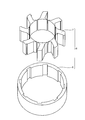
- FIG. 2 is a perspective view of the stator core of the inner rotor type motor according to the first embodiment.
- FIG. 3 is an exploded perspective view of the stator core of the inner rotor type motor according to the first embodiment.
- the stator 1 has an annular core back portion 8 and a stator core 6 having a teeth portion 7 protruding inward from the core back portion 8.
- the stator core 6 is formed by laminating a plurality of electromagnetic steel sheets, which are magnetic materials, in the axial direction of the shaft 104.
- Each of the teeth portions 7 is arranged on the inner peripheral side of the core back portion 8 at intervals in the circumferential direction.
- the stator core 6 has eight teeth portions 7.
- the stator 1 has a winding 9 having a coil wound around the teeth portion 7 and an insulator 10 that insulates the stator core 6 and the winding 9.
- the stator 1 has two phases and four poles and includes eight coils.
- the stator 1 contains two distributed winding coils for each slot between the teeth portions 7.
- the stator 1 is fitted on the inner peripheral surface of the frame 4.
- the stator 1 and the rotor 2 are arranged coaxially, and the rotor 2 is rotatable on the inner peripheral side of the stator core 6.
- FIG. 4 is a cross-sectional view of the stator of the inner rotor type motor according to the first embodiment.
- the teeth portion 7 is a portion that faces the rotor 2 and the slot forming portion 78 that forms a slot between the connecting portion 77 that engages with the core back portion 8 and the adjacent teeth portion 7. It has a peripheral portion 79. As shown in FIG. 4, each center line of the teeth portion 7 is a midpoint D in the circumferential direction of the inner peripheral portion 79 and a midpoint in the circumferential direction at the end of the slot forming portion 78 on the core back portion 8 side. Pass through with E.
- Each center line of the teeth portion 7 has an inclination of an angle ⁇ with respect to a line segment connecting the midpoint D in the circumferential direction of the inner peripheral portion 79 and the center point C of the core back portion 8.
- Each center line of the teeth portion 7 is inclined in the same direction in the circumferential direction from the line connecting the midpoint D in the circumferential direction of the inner peripheral portion 79 and the center point C of the core back portion 8.
- each center line of the teeth portion 7 is deviated in the clockwise direction from the line connecting the midpoint of the inner peripheral portion 79 in the circumferential direction and the center point C of the core back portion 8.
- each center line of the teeth portion 7 circumscribes a common circle centered on the center point C of the core back portion 8. As described above, since the center lines of the teeth portions 7 do not pass through a common point, the teeth portions 7 are not arranged radially in the inner rotor type motor 100 according to the first embodiment.
- the connecting portion 77 has a distance g from the line connecting the midpoint D in the circumferential direction of the inner peripheral portion 79 and the center point C in the core back portion 8 to the same side as the center line of the teeth portion 7 inclines in the circumferential direction. They are misaligned.
- the winding 9 has four main winding coil portions 109a, 109b, 109c, 109d and four auxiliary winding coil portions 110a, 110b, 110c, 110d.
- the four main winding coil portions 109a, 109b, 109c, 109d are connected in series with each other to form the main winding 109.
- the four auxiliary winding coil portions 110a, 110b, 110c, 110d are connected in series with each other to form the auxiliary winding 110.
- the main winding 109 and the auxiliary winding 110 are connected to form the winding 9.
- a rotating magnetic field is generated in the stator 1 by energizing the main winding 109 and the auxiliary winding 110.
- the rotor 2 receives a rotating magnetic field generated by the stator 1 and rotates about the central axis of the shaft 104.
- FIG. 5 is a circuit diagram of the inner rotor type motor according to the first embodiment.
- the series body in which the auxiliary winding 110 composed of the four auxiliary winding coil portions 110a, 110b, 110c, 110d shown in FIG. 4 and the capacitor 128 are connected in series is the four main winding coils shown in FIG.
- the main winding 109 including the parts 109a, 109b, 109c, and 109d and the single-phase AC power supply 127 are connected in parallel, respectively.
- auxiliary winding current Is flowing in the auxiliary winding 110 is about 90 ° ahead of the main winding current Im flowing in the main winding 109 by the capacitor 128.
- a rotating magnetic field is generated in the stator 1 along the rotation direction of the rotor 2.
- An ideal rotating magnetic field is obtained when the phase of the auxiliary winding current Is is advanced by 90 ° with respect to the main winding current Im.
- FIG. 6 is a perspective view of the rotor of the inner rotor type motor according to the first embodiment.
- the rotor 2 includes a tubular rotor core 129, a plurality of conductor rods 130 arranged at equal intervals in the circumferential direction on the outer peripheral surface side of the rotor core 129, and a plurality of conductor rods 130 of the rotor core 129. It has a short-circuit ring 131 for short-circuiting at both ends in the axial direction.
- the short-circuit ring 131 is made of a conductor such as aluminum or copper, and each conductor rod 130 is short-circuited at both ends in the axial direction of the rotor 2.
- the conductor rod 130 is made of a conductor such as aluminum or copper, and is inserted into the groove portion 141 of the rotor core 129. Further, the conductor rod 130 has a constant angle with respect to the rotation axis.
- the conductor rod 130 and the short-circuit ring 131 may be manufactured by a die-casting method in which molten metal is poured into the groove portion 141 of the rotor core 129 and both ends in the axial direction. Further, a metal rod may be inserted into the groove portion 141 of the adjacent rotor cores 129, and both ends of the metal rod may be soldered or brazed to the metal short-circuit ring 131. Further, in order to reduce the resistance of the conductor rod 130, a metal rod having a low resistivity such as a copper rod is inserted into the groove portion 141 of the rotor core 129, and then the conductor rod 130 and the short-circuit ring 131 are created by die casting. May be done.
- FIG. 7 is a cross-sectional view of the rotor of the inner rotor type motor according to the first embodiment.
- the rotor core 129 is formed by laminating a plurality of electromagnetic steel sheets made of a magnetic material in the direction of the rotation axis of the shaft 104. Further, the rotor core 129 protrudes radially outward from the annular back yoke portion 132 fitted to the outer peripheral surface of the shaft 104 and the back yoke portion 132, respectively, and is spaced apart from each other in the circumferential direction of the rotor core 129. It has a plurality of rotor teeth portions 133 arranged in the same manner. The rotor teeth portions 133 are arranged at equal intervals in the circumferential direction of the rotor core 129.
- FIG. 8 is a diagram showing how to arrange the windings of the inner rotor type motor according to the first embodiment. Since each center line of the teeth portion 7 circumscribes a common circle centered on the center point of the core back portion 8, the slot pitch L2 is such that the teeth portions 7 are arranged radially and the center of each teeth portion 7. The line is shorter than the slot pitch L1 when the line passes through the center point C of the core back portion 8. Therefore, a coil having a circumference shorter than the circumference of the slot on the core back portion 8 side of the teeth portion 7 arranged radially can be arranged in the slot. The circumference of the slot can be defined as the axial length of the tooth portion 7 and twice the sum of the slot pitch.
- the circumference of the coil can be defined as the length in the circumference direction on the inner diameter side of the coil. Further, since the connecting portion 77 is arranged on the same side as the direction in which the center line of the teeth portion 7 deviates from the line connecting the midpoint of the inner peripheral portion 79 in the circumferential direction and the center point C of the core back portion 8. , The slot pitch L2 can be further reduced.
- the inner rotor type motor 100 since the coils are distributed windings, one side of the coils is first inserted into all the slots, and all the coils are tilted in the same direction to arrange the coils in the slots. ..
- FIG. 9 is a diagram showing how to wind the coil of the inner rotor type motor according to the first embodiment.
- the main winding coil portion 109a is wound so as to surround the teeth portion 7a and the teeth portion 7b of the teeth portions 7a, 7b, 7c, 7d, 7e, 7f, 7g, and 7h.
- the auxiliary winding coil portion 110a adjacent to the main winding coil portion 109a in the counterclockwise direction includes the teeth portion 7b and the teeth portion 7c of the teeth portions 7a, 7b, 7c, 7d, 7e, 7f, 7g, and 7h. Wrapped around.
- the main winding coil portion 109b adjacent to the auxiliary winding coil portion 110a in the counterclockwise direction includes the teeth portion 7c and the teeth portion 7d among the teeth portions 7a, 7b, 7c, 7d, 7e, 7f, 7g, and 7h. Wrapped around.
- the auxiliary winding coil portion 110b, the main winding coil portion 109c, the auxiliary winding coil portion 110c, the main winding coil portion 109d, and the auxiliary winding coil portion 110d are wound in the same manner.
- the main winding coil portion 109a and the main winding coil portion 109b are arranged between the teeth portion 7b and the teeth portion 7c, the main winding coil portion 109b is arranged on the inner peripheral side, and the main winding coil portion 109a is on the outer periphery. It is wound so that it is placed on the side. That is, the main winding coil portions 109a, 109b, 109c, 109d and the auxiliary winding coil portions 110a, 110b, 110c, 110d are adjacent to each other in the circumferential direction, and the one in the clockwise direction is the inner peripheral side and the left. The coil is wound over the two tooth portions 7 so that the one in the clockwise direction is arranged on the outer peripheral side.
- each tooth portion 7 is tilted in the clockwise direction, and the outer peripheral side is moved in the clockwise direction. Therefore, the main winding coil portions 109a, 109b, 109c, 109d or the auxiliary winding coil portion 110a , 110b, 110c, 110d
- the teeth portion 7 is the main winding coil portion 109a, 109b, 109c, 109d.
- the distance between the tooth portions 7 becomes narrower toward the center side of the auxiliary winding coil portions 110a, 110b, 110c, 110d.
- the inner rotor type motor according to the first embodiment can be assembled without providing extra lengths in the main winding coil portions 109a, 109b, 109c, 109d and the auxiliary winding coil portions 110a, 110b, 110c, 110d. Can be done.
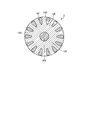
- FIG. 10 is a diagram showing a state in which the main winding coil portion and the auxiliary winding coil portion are arranged in a distributed winding in the slot of the inner rotor type motor according to the first embodiment. Finally, by assembling the core back portion 8 to the teeth portion 7, the stator 1 having the distributed winding coil is completed.
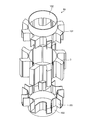
- FIG. 11 is an exploded perspective view of the insulator of the inner rotor type motor according to the first embodiment.
- FIG. 12 is a diagram showing a state in which an insulator is assembled to the teeth portion of the inner rotor type motor according to the first embodiment.
- the insulator 10 is arranged in a mounting portion 101 mounted on each of the plurality of teeth portions 7 and a portion in which the inner peripheral surface of the teeth portion 7 extends in the direction of the rotation axis of the rotor 2, and the insulator 10 is arranged in a portion of the plurality of teeth portions 7.
- a wall portion 102 that connects all the portions to be attached to each is provided.
- the insulator 10 can insulate the coil and the rotor 2 on the entire circumference. Further, since the position of each tooth portion 7 is determined by the insulator 10, the core back portion 8 can be easily press-fitted.
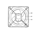
- FIG. 13 is a diagram showing a configuration of a blower using an inner rotor type motor according to the first embodiment.
- the ventilation fan 200 which is a blower, includes an inner rotor type electric motor 100 and a fan 201 attached to the shaft 104. A ventilation flow is formed by the inner rotor type motor 100 rotating the fan 201 through the shaft 104.
- the ventilation fan 200 is given as an example of the blower here, the blower to which the inner rotor type electric motor 100 is applied may be a fan.
- the teeth portions 7 in which the peripheral lengths of the main winding coil portions 109a, 109b, 109c, 109d and the auxiliary winding coil portions 110a, 110b, 110c, 110d are radially arranged Since it can be made shorter than the circumference of the slot on the core back portion 8 side of the above, the coil end can be made smaller and the motor efficiency can be improved.
- the configuration shown in the above embodiments is an example, and can be combined with another known technique, can be combined with each other, and does not deviate from the gist. It is also possible to omit or change a part of the configuration.
Landscapes
- Engineering & Computer Science (AREA)
- Power Engineering (AREA)
- Iron Core Of Rotating Electric Machines (AREA)
- Manufacture Of Motors, Generators (AREA)
Abstract
This inner rotor-type motor has: a stator (1) having a stator iron core (6) comprising an annular core back section (8) and a plurality of teeth sections (7) that protrude from the core back section (8) to the inner circumferential side, and distributed winding coils that are disposed in respective slots between the plurality of teeth sections (7) and wound around at least two teeth sections (7); and a rotor that is rotatably supported on the inner circumferential side of the stator with a gap between the rotor and the teeth sections (7). The center axis of each of the plurality of teeth sections (7) circumscribes a common circle centered on the center point of the core back section (8), and the circumferential length of the coil is shorter than the circumferential length of each slot when each of the teeth sections (7) is disposed radially.
Description
本開示は、環状の固定子の内周側に回転子が配置されるインナーロータ型電動機及びこれを備えた送風装置並びにインナーロータ型電動機の製造方法に関する。
The present disclosure relates to an inner rotor type motor in which a rotor is arranged on the inner peripheral side of an annular stator, a blower equipped with the rotor, and a method for manufacturing the inner rotor type motor.
インナーロータ型電動機は、環状の固定子の内周側に回転子が配置される。固定子は、環状のコアバック部及びコアバック部から内周側に突出する複数のティース部を有する固定子鉄心と、ティース部に巻き付けられたコイルとを有する。ティース部は、各々の中心線がコアバック部の環の中心点を通るように放射状に配置される。
In the inner rotor type motor, the rotor is placed on the inner peripheral side of the annular stator. The stator has an annular core back portion, a stator core having a plurality of teeth portions protruding inward from the core back portion, and a coil wound around the teeth portion. The teeth portions are arranged radially so that each center line passes through the center point of the ring of the core back portion.
コイルのうち、回転軸の方向においてティース部からはみ出す部分であるコイルエンドが大きくなると、コイルの重量を増加させるだけでなく、コイル周長が長くなることにより電気抵抗が増大する原因ともなる。したがって、電動機の効率を高めるためには、コイルエンドを低くすることが必要である。
If the coil end, which is the part of the coil that protrudes from the teeth portion in the direction of the rotation axis, becomes large, not only the weight of the coil increases, but also the electrical resistance increases due to the lengthening of the coil circumference. Therefore, in order to increase the efficiency of the motor, it is necessary to lower the coil end.
特許文献1には、固定子鉄心をティース部とコアバック部とに分割することにより、分布巻きのコイルのコイルエンドを低く抑えたインナーロータ型電動機であるモータが開示されている。特許文献1に開示されるモータは、予めコイル状にした巻線コイルをティース部同士の間であるスロットにコアバック部側から後入れで配置することによって、ティース部に分布巻きでコイルを巻き付けた固定子を形成している。
Patent Document 1 discloses a motor which is an inner rotor type motor in which the coil end of a distributed winding coil is suppressed low by dividing the stator core into a teeth portion and a core back portion. In the motor disclosed in Patent Document 1, a pre-coiled winding coil is placed in a slot between the teeth portions in a post-insertion manner from the core back portion side, so that the coil is wound around the teeth portions in a distributed winding manner. Forming a stator.
ティース部は放射状に配列されるため、コアバック部側ほどスロットピッチは広くなる。したがって、上記特許文献1に開示されるモータは、スロットの周長よりも周長が長いコイルでないと、コイルをスロットに後入れできない。このため、特許文献1に開示されるモータでは、複数のティース部を放射状に配置した状態におけるスロットの周長よりも短い周長のコイルをスロットに配置することはできなかった。したがって、スロットに配置したコイルは周長に余剰が生じ、コイルをスロットに入れた状態におけるコイルエンドが大きくなってしまう。
Since the teeth are arranged radially, the slot pitch becomes wider toward the core back side. Therefore, in the motor disclosed in Patent Document 1, the coil cannot be post-inserted into the slot unless the coil has a circumference longer than the circumference of the slot. Therefore, in the motor disclosed in Patent Document 1, it is not possible to arrange a coil having a peripheral length shorter than the peripheral length of the slot in a state where a plurality of teeth portions are arranged radially in the slot. Therefore, the coil arranged in the slot has a surplus in the peripheral length, and the coil end in the state where the coil is inserted in the slot becomes large.
本開示は、上記に鑑みてなされたものであって、コイルエンドを小型化したインナーロータ型電動機を得ることを目的とする。
The present disclosure has been made in view of the above, and an object of the present disclosure is to obtain an inner rotor type motor having a miniaturized coil end.
上述した課題を解決し、目的を達成するために、本開示に係るインナーロータ型電動機は、環状のコアバック部と、コアバック部から内周側に突出する複数のティース部とを備えた固定子鉄心と、複数のティース部の各々の間のスロットに配置されて複数のティース部の二つ以上に巻き付けられた分布巻きのコイルとを有する固定子と、ティース部との間に隙間を空けて固定子の内周側に回転可能に支持された回転子とを有する。複数のティース部の各々の中心線は、コアバック部の中心点を中心とする共通の円に外接する。コイルの周長は、ティース部の各々が放射状に配置された場合のスロットの周長よりも短い。
In order to solve the above-mentioned problems and achieve the object, the inner rotor type motor according to the present disclosure is fixed with an annular core back portion and a plurality of teeth portions protruding from the core back portion to the inner peripheral side. Leave a gap between the stator and the stator, which has a rotor core and a distributed winding coil arranged in a slot between each of the plurality of teeth portions and wound around two or more of the plurality of teeth portions. It has a rotor that is rotatably supported on the inner peripheral side of the stator. The center line of each of the plurality of teeth portions circumscribes a common circle centered on the center point of the core back portion. The circumference of the coil is shorter than the circumference of the slot when each of the teeth is arranged radially.
本開示に係るインナーロータ型電動機は、コイルエンドを小型化できるという効果を奏する。
The inner rotor type motor according to the present disclosure has the effect of being able to miniaturize the coil end.
以下に、実施の形態に係るインナーロータ型電動機、送風装置及びインナーロータ型電動機の製造方法を図面に基づいて詳細に説明する。なお、この実施の形態により本開示が限定されるものではない。
The manufacturing method of the inner rotor type motor, the blower, and the inner rotor type motor according to the embodiment will be described in detail below based on the drawings. The present disclosure is not limited to this embodiment.
実施の形態1.
図1は、実施の形態1に係るインナーロータ型電動機の分解斜視図である。インナーロータ型電動機100は、環状の固定子1と、固定子1の内周側に配置された回転子2と、回転子2を回転可能に支持する軸受3a,3bと、軸受3aを保持するフレーム4と、軸受3bを保持するブラケット5とを有する。固定子1及び回転子2は、フレーム4及びブラケット5がなす外郭の内部空間に収容される。軸受3a,3bは、回転子2のうちシャフト104を回転可能に支持している。Embodiment 1.
FIG. 1 is an exploded perspective view of the inner rotor type motor according to the first embodiment. The innerrotor type motor 100 holds an annular stator 1, a rotor 2 arranged on the inner peripheral side of the stator 1, bearings 3a and 3b that rotatably support the rotor 2, and a bearing 3a. It has a frame 4 and a bracket 5 for holding the bearing 3b. The stator 1 and the rotor 2 are housed in the inner space of the outer shell formed by the frame 4 and the bracket 5. The bearings 3a and 3b rotatably support the shaft 104 of the rotor 2.
図1は、実施の形態1に係るインナーロータ型電動機の分解斜視図である。インナーロータ型電動機100は、環状の固定子1と、固定子1の内周側に配置された回転子2と、回転子2を回転可能に支持する軸受3a,3bと、軸受3aを保持するフレーム4と、軸受3bを保持するブラケット5とを有する。固定子1及び回転子2は、フレーム4及びブラケット5がなす外郭の内部空間に収容される。軸受3a,3bは、回転子2のうちシャフト104を回転可能に支持している。
FIG. 1 is an exploded perspective view of the inner rotor type motor according to the first embodiment. The inner
図2は、実施の形態1に係るインナーロータ型電動機の固定子鉄心の斜視図である。図3は、実施の形態1に係るインナーロータ型電動機の固定子鉄心の分解斜視図である。固定子1は、環状のコアバック部8及びコアバック部8から内周側に突出するティース部7を備えた固定子鉄心6を有する。固定子鉄心6は、磁性体である電磁鋼板をシャフト104の軸方向に複数枚積層して構成されている。ティース部7の各々は、コアバック部8の内周側に周方向に互いに間隔をおいて配置されている。固定子鉄心6は、八つのティース部7を有する。
FIG. 2 is a perspective view of the stator core of the inner rotor type motor according to the first embodiment. FIG. 3 is an exploded perspective view of the stator core of the inner rotor type motor according to the first embodiment. The stator 1 has an annular core back portion 8 and a stator core 6 having a teeth portion 7 protruding inward from the core back portion 8. The stator core 6 is formed by laminating a plurality of electromagnetic steel sheets, which are magnetic materials, in the axial direction of the shaft 104. Each of the teeth portions 7 is arranged on the inner peripheral side of the core back portion 8 at intervals in the circumferential direction. The stator core 6 has eight teeth portions 7.
また、図1に示すように、固定子1は、ティース部7に巻かれたコイルを備えた巻線9と、固定子鉄心6と巻線9とを絶縁するインシュレータ10とを有する。固定子1は、2相4極であり八つのコイルを備える。固定子1は、ティース部7同士の間のスロット一つにつき、分布巻きのコイルが二つ入っている。
Further, as shown in FIG. 1, the stator 1 has a winding 9 having a coil wound around the teeth portion 7 and an insulator 10 that insulates the stator core 6 and the winding 9. The stator 1 has two phases and four poles and includes eight coils. The stator 1 contains two distributed winding coils for each slot between the teeth portions 7.
固定子1は、フレーム4の内周面に嵌め込まれている。固定子1と回転子2とは同軸に配置されており、回転子2は固定子鉄心6の内周側において回転自在である。
The stator 1 is fitted on the inner peripheral surface of the frame 4. The stator 1 and the rotor 2 are arranged coaxially, and the rotor 2 is rotatable on the inner peripheral side of the stator core 6.
図4は、実施の形態1に係るインナーロータ型電動機の固定子の断面図である。ティース部7は、コアバック部8と係合する部分である接続部77と、隣接するティース部7との間にスロットを形成するスロット形成部78と、回転子2と対向する部分である内周部79とを備えている。図4に示すように、ティース部7の各々の中心線は、内周部79の周方向の中点Dと、スロット形成部78のコアバック部8側の端部での周方向の中点Eとを通る。ティース部7の各々の中心線は、内周部79の周方向の中点Dとコアバック部8の中心点Cとを結ぶ線分に対して角度θの傾きを有している。ティース部7の各々の中心線は、内周部79の周方向の中点Dとコアバック部8の中心点Cとを結ぶ線分から周方向において同じ向きに傾いている。図4においては、ティース部7の各々の中心線は、内周部79の周方向の中点とコアバック部8の中心点Cとを結ぶ線分から右回り方向にずれている。このため、シャフト104に垂直な面において、ティース部7の各々の中心線は、コアバック部8の中心点Cを中心とする共通の円に外接している。このように、ティース部7の各々の中心線が共通する一点を通らないため、実施の形態1に係るインナーロータ型電動機100においては、ティース部7は、放射状に配置されていない。
FIG. 4 is a cross-sectional view of the stator of the inner rotor type motor according to the first embodiment. The teeth portion 7 is a portion that faces the rotor 2 and the slot forming portion 78 that forms a slot between the connecting portion 77 that engages with the core back portion 8 and the adjacent teeth portion 7. It has a peripheral portion 79. As shown in FIG. 4, each center line of the teeth portion 7 is a midpoint D in the circumferential direction of the inner peripheral portion 79 and a midpoint in the circumferential direction at the end of the slot forming portion 78 on the core back portion 8 side. Pass through with E. Each center line of the teeth portion 7 has an inclination of an angle θ with respect to a line segment connecting the midpoint D in the circumferential direction of the inner peripheral portion 79 and the center point C of the core back portion 8. Each center line of the teeth portion 7 is inclined in the same direction in the circumferential direction from the line connecting the midpoint D in the circumferential direction of the inner peripheral portion 79 and the center point C of the core back portion 8. In FIG. 4, each center line of the teeth portion 7 is deviated in the clockwise direction from the line connecting the midpoint of the inner peripheral portion 79 in the circumferential direction and the center point C of the core back portion 8. Therefore, on the plane perpendicular to the shaft 104, each center line of the teeth portion 7 circumscribes a common circle centered on the center point C of the core back portion 8. As described above, since the center lines of the teeth portions 7 do not pass through a common point, the teeth portions 7 are not arranged radially in the inner rotor type motor 100 according to the first embodiment.
接続部77は、内周部79の周方向の中点Dとコアバック部8の中心点Cとを結ぶ線分からティース部7の中心線が周方向において傾く方向と同じ側に、距離gだけずれて配置されている。
The connecting portion 77 has a distance g from the line connecting the midpoint D in the circumferential direction of the inner peripheral portion 79 and the center point C in the core back portion 8 to the same side as the center line of the teeth portion 7 inclines in the circumferential direction. They are misaligned.
巻線9は、四つの主巻線コイル部109a,109b,109c,109dと、四つの補助巻線コイル部110a,110b,110c,110dとを有する。四つの主巻線コイル部109a,109b,109c,109dは、互いに直列に接続されて主巻線109を構成している。四つの補助巻線コイル部110a,110b,110c,110dは、互いに直列に接続されて補助巻線110を構成している。主巻線109と補助巻線110とが結線されて巻線9が構成されている。
The winding 9 has four main winding coil portions 109a, 109b, 109c, 109d and four auxiliary winding coil portions 110a, 110b, 110c, 110d. The four main winding coil portions 109a, 109b, 109c, 109d are connected in series with each other to form the main winding 109. The four auxiliary winding coil portions 110a, 110b, 110c, 110d are connected in series with each other to form the auxiliary winding 110. The main winding 109 and the auxiliary winding 110 are connected to form the winding 9.
主巻線109及び補助巻線110に通電されることによって、固定子1に回転磁界が発生する。回転子2は、固定子1が発生させる回転磁界を受けてシャフト104の中心軸を中心に回転する。
A rotating magnetic field is generated in the stator 1 by energizing the main winding 109 and the auxiliary winding 110. The rotor 2 receives a rotating magnetic field generated by the stator 1 and rotates about the central axis of the shaft 104.
図5は、実施の形態1に係るインナーロータ型電動機の回路図である。図4に示した四つの補助巻線コイル部110a,110b,110c,110dからなる補助巻線110とコンデンサ128とが直列に接続された直列体は、図4に示した四つの主巻線コイル部109a,109b,109c,109dからなる主巻線109と単相交流電源127とにそれぞれ並列に接続されている。
FIG. 5 is a circuit diagram of the inner rotor type motor according to the first embodiment. The series body in which the auxiliary winding 110 composed of the four auxiliary winding coil portions 110a, 110b, 110c, 110d shown in FIG. 4 and the capacitor 128 are connected in series is the four main winding coils shown in FIG. The main winding 109 including the parts 109a, 109b, 109c, and 109d and the single-phase AC power supply 127 are connected in parallel, respectively.
また、補助巻線110に流れる補助巻線電流Isは、コンデンサ128によって主巻線109に流れる主巻線電流Imよりも電流位相が90°程度進んでいる。これによって、固定子1には回転子2の回転方向に沿った回転磁界が生じる。主巻線電流Imに対して補助巻線電流Isの位相が90°進んでいる時に理想的な回転磁界が得られる。
Further, the auxiliary winding current Is flowing in the auxiliary winding 110 is about 90 ° ahead of the main winding current Im flowing in the main winding 109 by the capacitor 128. As a result, a rotating magnetic field is generated in the stator 1 along the rotation direction of the rotor 2. An ideal rotating magnetic field is obtained when the phase of the auxiliary winding current Is is advanced by 90 ° with respect to the main winding current Im.
図6は、実施の形態1に係るインナーロータ型電動機の回転子の斜視図である。回転子2は、筒形の回転子鉄心129と、回転子鉄心129の外周面側に周方向に等間隔に並べられた複数の導体棒130と、複数の導体棒130を回転子鉄心129の軸方向両端で短絡させる短絡環131とを有する。短絡環131は、アルミニウム又は銅といった導体からなり、各導体棒130を回転子2の軸方向両端で短絡させている。
FIG. 6 is a perspective view of the rotor of the inner rotor type motor according to the first embodiment. The rotor 2 includes a tubular rotor core 129, a plurality of conductor rods 130 arranged at equal intervals in the circumferential direction on the outer peripheral surface side of the rotor core 129, and a plurality of conductor rods 130 of the rotor core 129. It has a short-circuit ring 131 for short-circuiting at both ends in the axial direction. The short-circuit ring 131 is made of a conductor such as aluminum or copper, and each conductor rod 130 is short-circuited at both ends in the axial direction of the rotor 2.
導体棒130は、アルミニウム又は銅といった導体からなり、回転子鉄心129の溝部141に挿入されている。また、導体棒130は、回転軸線に対して一定の角度を有する。
The conductor rod 130 is made of a conductor such as aluminum or copper, and is inserted into the groove portion 141 of the rotor core 129. Further, the conductor rod 130 has a constant angle with respect to the rotation axis.
導体棒130及び短絡環131は、回転子鉄心129の溝部141及び軸方向両端部に溶融した金属を流し込むダイカスト製法によって製作されても良い。また、隣り合う回転子鉄心129の溝部141に金属棒を挿入し、金属棒の両端を金属製の短絡環131にはんだ付け、又はろう付けして作成されても良い。さらに、導体棒130の抵抗を低減するために、銅棒のように抵抗率の低い金属棒を回転子鉄心129の溝部141に挿入し、その後、ダイカストで導体棒130と短絡環131とが作成されても良い。
The conductor rod 130 and the short-circuit ring 131 may be manufactured by a die-casting method in which molten metal is poured into the groove portion 141 of the rotor core 129 and both ends in the axial direction. Further, a metal rod may be inserted into the groove portion 141 of the adjacent rotor cores 129, and both ends of the metal rod may be soldered or brazed to the metal short-circuit ring 131. Further, in order to reduce the resistance of the conductor rod 130, a metal rod having a low resistivity such as a copper rod is inserted into the groove portion 141 of the rotor core 129, and then the conductor rod 130 and the short-circuit ring 131 are created by die casting. May be done.
図7は、実施の形態1に係るインナーロータ型電動機の回転子の断面図である。回転子鉄心129は、磁性体からなる複数枚の電磁鋼板によってシャフト104の回転軸線方向に積層されて構成されている。また、回転子鉄心129は、シャフト104の外周面に嵌め合わされた円環状のバックヨーク部132と、バックヨーク部132から径方向外側へそれぞれ突出し、回転子鉄心129の周方向について互いに間隔を置いて配置された複数の回転子ティース部133とを有している。各回転子ティース部133は、回転子鉄心129の周方向について等間隔に配置されている。
FIG. 7 is a cross-sectional view of the rotor of the inner rotor type motor according to the first embodiment. The rotor core 129 is formed by laminating a plurality of electromagnetic steel sheets made of a magnetic material in the direction of the rotation axis of the shaft 104. Further, the rotor core 129 protrudes radially outward from the annular back yoke portion 132 fitted to the outer peripheral surface of the shaft 104 and the back yoke portion 132, respectively, and is spaced apart from each other in the circumferential direction of the rotor core 129. It has a plurality of rotor teeth portions 133 arranged in the same manner. The rotor teeth portions 133 are arranged at equal intervals in the circumferential direction of the rotor core 129.
図8は、実施の形態1に係るインナーロータ型電動機の巻線の配置の仕方を示す図である。ティース部7の各々の中心線が、コアバック部8の中心点を中心とする共通する円に外接することにより、スロットピッチL2は、ティース部7が放射状に配置されて各ティース部7の中心線がコアバック部8の中心点Cを通る場合のスロットピッチL1よりも短くなる。このため、放射状に配置されたティース部7のコアバック部8側でのスロットの周長よりも周長が短いコイルをスロットに配置することができる。なお、スロットの周長とは、ティース部7の軸方向の長さと、スロットピッチとの和の2倍の長さと定義できる。また、コイルの周長とは、コイルの内径側での周方向の長さと定義できる。また、内周部79の周方向の中点とコアバック部8の中心点Cとを結ぶ線分からティース部7の中心線がずれる方向と同じ側に接続部77がずれて配置されているため、スロットピッチL2をさらに小さくできる。
FIG. 8 is a diagram showing how to arrange the windings of the inner rotor type motor according to the first embodiment. Since each center line of the teeth portion 7 circumscribes a common circle centered on the center point of the core back portion 8, the slot pitch L2 is such that the teeth portions 7 are arranged radially and the center of each teeth portion 7. The line is shorter than the slot pitch L1 when the line passes through the center point C of the core back portion 8. Therefore, a coil having a circumference shorter than the circumference of the slot on the core back portion 8 side of the teeth portion 7 arranged radially can be arranged in the slot. The circumference of the slot can be defined as the axial length of the tooth portion 7 and twice the sum of the slot pitch. Further, the circumference of the coil can be defined as the length in the circumference direction on the inner diameter side of the coil. Further, since the connecting portion 77 is arranged on the same side as the direction in which the center line of the teeth portion 7 deviates from the line connecting the midpoint of the inner peripheral portion 79 in the circumferential direction and the center point C of the core back portion 8. , The slot pitch L2 can be further reduced.
実施の形態1に係るインナーロータ型電動機100は、コイルが分布巻きであるため、先にすべてのスロットにコイルの片側を入れ、全てのコイルを同じ方向に倒すことにより、スロットにコイルを配置する。
In the inner rotor type motor 100 according to the first embodiment, since the coils are distributed windings, one side of the coils is first inserted into all the slots, and all the coils are tilted in the same direction to arrange the coils in the slots. ..
図9は、実施の形態1に係るインナーロータ型電動機のコイルの巻き方を示す図である。主巻線コイル部109aは、ティース部7a,7b,7c,7d,7e,7f,7g,7hのうち、ティース部7aとティース部7bとを囲むように巻かれる。主巻線コイル部109aの左回り方向に隣接する補助巻線コイル部110aは、ティース部7a,7b,7c,7d,7e,7f,7g,7hのうち、ティース部7bとティース部7cとを囲むように巻かれる。補助巻線コイル部110aの左回り方向に隣接する主巻線コイル部109bは、ティース部7a,7b,7c,7d,7e,7f,7g,7hのうち、ティース部7cとティース部7dとを囲むように巻かれる。以下同様に、補助巻線コイル部110b、主巻線コイル部109c、補助巻線コイル部110c、主巻線コイル部109d及び補助巻線コイル部110dが巻かれる。
FIG. 9 is a diagram showing how to wind the coil of the inner rotor type motor according to the first embodiment. The main winding coil portion 109a is wound so as to surround the teeth portion 7a and the teeth portion 7b of the teeth portions 7a, 7b, 7c, 7d, 7e, 7f, 7g, and 7h. The auxiliary winding coil portion 110a adjacent to the main winding coil portion 109a in the counterclockwise direction includes the teeth portion 7b and the teeth portion 7c of the teeth portions 7a, 7b, 7c, 7d, 7e, 7f, 7g, and 7h. Wrapped around. The main winding coil portion 109b adjacent to the auxiliary winding coil portion 110a in the counterclockwise direction includes the teeth portion 7c and the teeth portion 7d among the teeth portions 7a, 7b, 7c, 7d, 7e, 7f, 7g, and 7h. Wrapped around. Similarly, the auxiliary winding coil portion 110b, the main winding coil portion 109c, the auxiliary winding coil portion 110c, the main winding coil portion 109d, and the auxiliary winding coil portion 110d are wound in the same manner.
ティース部7bとティース部7cとの間には、主巻線コイル部109a及び主巻線コイル部109bが、主巻線コイル部109bが内周側に配置され、主巻線コイル部109aが外周側に配置されるように巻かれる。すなわち、主巻線コイル部109a,109b,109c,109d及び補助巻線コイル部110a,110b,110c,110dは、周方向い互いに隣り合う二つのうち右回り方向にあるものが内周側、左回り方向にあるものが外周側に配置するように、二つのティース部7にまたがって巻かれる。
The main winding coil portion 109a and the main winding coil portion 109b are arranged between the teeth portion 7b and the teeth portion 7c, the main winding coil portion 109b is arranged on the inner peripheral side, and the main winding coil portion 109a is on the outer periphery. It is wound so that it is placed on the side. That is, the main winding coil portions 109a, 109b, 109c, 109d and the auxiliary winding coil portions 110a, 110b, 110c, 110d are adjacent to each other in the circumferential direction, and the one in the clockwise direction is the inner peripheral side and the left. The coil is wound over the two tooth portions 7 so that the one in the clockwise direction is arranged on the outer peripheral side.
図9において、各ティース部7は、右回り方向に傾いており、外周側は右回り方向に移動しているので、主巻線コイル部109a,109b,109c,109d又は補助巻線コイル部110a,110b,110c,110dの右回り方向の端部を内周側に配置した状態で左回り方向の端部を重ねる場合には、ティース部7が主巻線コイル部109a,109b,109c,109d又は補助巻線コイル部110a,110b,110c,110dの中央側に寄ってティース部7同士の間隔が狭くなっていることになる。このため、実施の形態1に係るインナーロータ型電動機は、主巻線コイル部109a,109b,109c,109d及び補助巻線コイル部110a,110b,110c,110dに余長を設けなくても組み立てることができる。
In FIG. 9, each tooth portion 7 is tilted in the clockwise direction, and the outer peripheral side is moved in the clockwise direction. Therefore, the main winding coil portions 109a, 109b, 109c, 109d or the auxiliary winding coil portion 110a , 110b, 110c, 110d When the clockwise ends are arranged on the inner peripheral side and the counterclockwise ends are overlapped, the teeth portion 7 is the main winding coil portion 109a, 109b, 109c, 109d. Alternatively, the distance between the tooth portions 7 becomes narrower toward the center side of the auxiliary winding coil portions 110a, 110b, 110c, 110d. Therefore, the inner rotor type motor according to the first embodiment can be assembled without providing extra lengths in the main winding coil portions 109a, 109b, 109c, 109d and the auxiliary winding coil portions 110a, 110b, 110c, 110d. Can be done.
図10は、実施の形態1に係るインナーロータ型電動機のスロットに分布巻きで主巻線コイル部及び補助巻線コイル部を配置した状態を示す図である。最後にコアバック部8をティース部7に組み付けることにより、分布巻きのコイルを有する固定子1が完成する。
FIG. 10 is a diagram showing a state in which the main winding coil portion and the auxiliary winding coil portion are arranged in a distributed winding in the slot of the inner rotor type motor according to the first embodiment. Finally, by assembling the core back portion 8 to the teeth portion 7, the stator 1 having the distributed winding coil is completed.
図11は、実施の形態1に係るインナーロータ型電動機のインシュレータの分解斜視図である。図12は、実施の形態1に係るインナーロータ型電動機のティース部にインシュレータを組み付けた状態を示す図である。インシュレータ10は、複数のティース部7の各々に装着される装着部101と、ティース部7の内周面を回転子2の回転軸の方向に延長した部分に配置され、複数のティース部7の各々に装着される部分を全て繋ぐ壁部102とを備える。実施の形態1に係るインナーロータ型電動機100では、壁部102が内径側で繋がっているため、インシュレータ10はコイルと回転子2とを全周において絶縁できる。また、各ティース部7の位置がインシュレータ10により決められることとなるため、コアバック部8の圧入が容易となる。
FIG. 11 is an exploded perspective view of the insulator of the inner rotor type motor according to the first embodiment. FIG. 12 is a diagram showing a state in which an insulator is assembled to the teeth portion of the inner rotor type motor according to the first embodiment. The insulator 10 is arranged in a mounting portion 101 mounted on each of the plurality of teeth portions 7 and a portion in which the inner peripheral surface of the teeth portion 7 extends in the direction of the rotation axis of the rotor 2, and the insulator 10 is arranged in a portion of the plurality of teeth portions 7. A wall portion 102 that connects all the portions to be attached to each is provided. In the inner rotor type motor 100 according to the first embodiment, since the wall portion 102 is connected on the inner diameter side, the insulator 10 can insulate the coil and the rotor 2 on the entire circumference. Further, since the position of each tooth portion 7 is determined by the insulator 10, the core back portion 8 can be easily press-fitted.
図13は、実施の形態1に係るインナーロータ型電動機を用いた送風装置の構成を示す図である。送風装置である換気扇200は、インナーロータ型電動機100と、シャフト104に取り付けられたファン201とを備えている。インナーロータ型電動機100がシャフト104を通じてファン201を回転させることにより、換気流が形成される。なお、ここでは換気扇200を送風装置の例に挙げたが、インナーロータ型電動機100を適用する送風装置は扇風機であってもよい。
FIG. 13 is a diagram showing a configuration of a blower using an inner rotor type motor according to the first embodiment. The ventilation fan 200, which is a blower, includes an inner rotor type electric motor 100 and a fan 201 attached to the shaft 104. A ventilation flow is formed by the inner rotor type motor 100 rotating the fan 201 through the shaft 104. Although the ventilation fan 200 is given as an example of the blower here, the blower to which the inner rotor type electric motor 100 is applied may be a fan.
実施の形態1に係るインナーロータ型電動機100は、主巻線コイル部109a,109b,109c,109d及び補助巻線コイル部110a,110b,110c,110dの周長を放射状に配置されたティース部7のコアバック部8側でのスロットの周長よりも短くできるため、コイルエンドを小さくして電動機効率を高めることができる。
In the inner rotor type motor 100 according to the first embodiment, the teeth portions 7 in which the peripheral lengths of the main winding coil portions 109a, 109b, 109c, 109d and the auxiliary winding coil portions 110a, 110b, 110c, 110d are radially arranged. Since it can be made shorter than the circumference of the slot on the core back portion 8 side of the above, the coil end can be made smaller and the motor efficiency can be improved.
以上の実施の形態に示した構成は、一例を示すものであり、別の公知の技術と組み合わせることも可能であるし、実施の形態同士を組み合わせることも可能であるし、要旨を逸脱しない範囲で、構成の一部を省略、変更することも可能である。
The configuration shown in the above embodiments is an example, and can be combined with another known technique, can be combined with each other, and does not deviate from the gist. It is also possible to omit or change a part of the configuration.
1 固定子、2 回転子、3a,3b 軸受、4 フレーム、5 ブラケット、6 固定子鉄心、7,7a,7b,7c,7d,7e,7f,7g,7h ティース部、8 コアバック部、9 巻線、10 インシュレータ、77 接続部、78 スロット形成部、79 内周部、100 インナーロータ型電動機、101 装着部、102 壁部、104 シャフト、109 主巻線、109a,109b,109c,109d 主巻線コイル部、110 補助巻線、110a,110b,110c,110d 補助巻線コイル部、127 単相交流電源、128 コンデンサ、129 回転子鉄心、130 導体棒、131 短絡環、132 バックヨーク部、133 回転子ティース部、141 溝部、200 換気扇、201 ファン。
1 stator, 2 rotor, 3a, 3b bearing, 4 frame, 5 bracket, 6 stator core, 7,7a, 7b, 7c, 7d, 7e, 7f, 7g, 7h teeth part, 8 core back part, 9 Winding, 10 insulator, 77 connection part, 78 slot forming part, 79 inner circumference part, 100 inner rotor type electric motor, 101 mounting part, 102 wall part, 104 shaft, 109 main winding, 109a, 109b, 109c, 109d main Winding coil part, 110 auxiliary winding, 110a, 110b, 110c, 110d Auxiliary winding coil part, 127 single-phase AC power supply, 128 condenser, 129 rotor core, 130 conductor rod, 131 short-circuit ring, 132 back yoke part, 133 rotor teeth part, 141 groove part, 200 ventilation fan, 201 fan.
Claims (5)
- 環状のコアバック部と、前記コアバック部から内周側に突出する複数のティース部とを備えた固定子鉄心と、複数の前記ティース部の各々の間のスロットに配置されて複数の前記ティース部の二つ以上に巻き付けられた分布巻きのコイルとを有する固定子と、
前記ティース部との間に隙間を空けて前記固定子の内周側に回転可能に支持された回転子とを有し、
複数の前記ティース部の各々の中心線は、前記コアバック部の中心点を中心とする共通の円に外接し、
前記コイルの周長は、前記ティース部の各々が放射状に配置された場合の前記スロットの周長よりも短いことを特徴とするインナーロータ型電動機。 A stator core having an annular core back portion and a plurality of teeth portions protruding inward from the core back portion, and a plurality of the teeth arranged in a slot between each of the plurality of the teeth portions. A stator with a distributed winding coil wound around two or more parts, and
It has a rotor that is rotatably supported on the inner peripheral side of the stator with a gap between it and the teeth portion.
The center line of each of the plurality of teeth portions circumscribes a common circle centered on the center point of the core back portion.
An inner rotor type motor characterized in that the peripheral length of the coil is shorter than the peripheral length of the slot when each of the teeth portions is arranged radially. - 前記固定子は、前記ティース部に装着されて、前記ティース部と前記コイルとを電気的に絶縁するインシュレータを備え、
前記インシュレータは、複数の前記ティース部の各々に装着される装着部と、前記ティース部の内周面を前記回転子の回転軸の方向に延長した部分に配置され、前記装着部を全て繋ぐ壁部とを備えることを特徴とする請求項1に記載のインナーロータ型電動機。 The stator is attached to the teeth portion and includes an insulator that electrically insulates the teeth portion and the coil.
The insulator is arranged in a mounting portion mounted on each of the plurality of the teeth portions and a portion in which the inner peripheral surface of the teeth portion extends in the direction of the rotation axis of the rotor, and a wall connecting all the mounting portions. The inner rotor type motor according to claim 1, further comprising a unit. - 前記ティース部は、前記コアバック部に接続される接続部と、前記回転子と対向する内周部とを有し、
前記接続部は、
前記ティース部の中心線が、前記内周部の周方向の中点と前記コアバック部の中心点とを結ぶ線分から前記ティース部の中心線がずれる側と同じ側にずれて配置されていることを特徴とする請求項1又は2に記載のインナーロータ型電動機。 The teeth portion has a connecting portion connected to the core back portion and an inner peripheral portion facing the rotor.
The connection part
The center line of the teeth portion is arranged so as to be offset from the line connecting the midpoint of the inner peripheral portion in the circumferential direction and the center point of the core back portion to the same side as the side where the center line of the teeth portion is deviated. The inner rotor type motor according to claim 1 or 2, wherein the motor is characterized by the above. - 請求項1から3のいずれか1項に記載のインナーロータ型電動機と、前記インナーロータ型電動機によって駆動されるファンとを有することを特徴とする送風装置。 A blower having an inner rotor type motor according to any one of claims 1 to 3 and a fan driven by the inner rotor type motor.
- 請求項1から3のいずれか1項に記載のインナーロータ型電動機の製造方法であって、
前記ティース部のうち前記回転子と対向する内周部の周方向の中点と前記コアバック部の中心点とを結ぶ線分から前記ティース部の中心線がずれる方向側の前記スロットから前記コイルを挿入することを特徴とするインナーロータ型電動機の製造方法。 The method for manufacturing an inner rotor type motor according to any one of claims 1 to 3.
The coil is inserted from the slot on the side in which the center line of the teeth portion deviates from the line connecting the midpoint of the inner peripheral portion facing the rotor and the center point of the core back portion of the teeth portion. A method for manufacturing an inner rotor type motor, which is characterized by being inserted.
Priority Applications (2)
| Application Number | Priority Date | Filing Date | Title |
|---|---|---|---|
| PCT/JP2019/049656 WO2021124487A1 (en) | 2019-12-18 | 2019-12-18 | Inner rotor-type motor, blowing device, and method for manufacturing inner rotor-type motor |
| JP2021565239A JP7313476B2 (en) | 2019-12-18 | 2019-12-18 | INNER ROTOR ELECTRIC MOTOR, BLOWER DEVICE, AND INNER ROTOR ELECTRIC MANUFACTURING METHOD |
Applications Claiming Priority (1)
| Application Number | Priority Date | Filing Date | Title |
|---|---|---|---|
| PCT/JP2019/049656 WO2021124487A1 (en) | 2019-12-18 | 2019-12-18 | Inner rotor-type motor, blowing device, and method for manufacturing inner rotor-type motor |
Publications (1)
| Publication Number | Publication Date |
|---|---|
| WO2021124487A1 true WO2021124487A1 (en) | 2021-06-24 |
Family
ID=76477430
Family Applications (1)
| Application Number | Title | Priority Date | Filing Date |
|---|---|---|---|
| PCT/JP2019/049656 WO2021124487A1 (en) | 2019-12-18 | 2019-12-18 | Inner rotor-type motor, blowing device, and method for manufacturing inner rotor-type motor |
Country Status (2)
| Country | Link |
|---|---|
| JP (1) | JP7313476B2 (en) |
| WO (1) | WO2021124487A1 (en) |
Citations (7)
| Publication number | Priority date | Publication date | Assignee | Title |
|---|---|---|---|---|
| JP2000184632A (en) * | 1998-12-09 | 2000-06-30 | Denso Corp | Electric rotating machine and its manufacture |
| JP2000209821A (en) * | 1999-01-12 | 2000-07-28 | Honda Motor Co Ltd | Manufacturing device of motor |
| JP2001346366A (en) * | 2000-03-27 | 2001-12-14 | Matsushita Electric Ind Co Ltd | Motor, method of manufacturing the same and compressor using the same |
| JP2003324926A (en) * | 2002-04-30 | 2003-11-14 | Seiko Epson Corp | Armature and dc motor having armature |
| JP2005204476A (en) * | 2004-01-19 | 2005-07-28 | Mitsui High Tec Inc | Divided laminated stator core |
| JP2015080341A (en) * | 2013-10-17 | 2015-04-23 | ミネベア株式会社 | Insulator, stator comprising the same, and motor comprising the same |
| JP2019092355A (en) * | 2017-11-17 | 2019-06-13 | 株式会社ジェイテクト | Motor stator |
-
2019
- 2019-12-18 JP JP2021565239A patent/JP7313476B2/en active Active
- 2019-12-18 WO PCT/JP2019/049656 patent/WO2021124487A1/en active Application Filing
Patent Citations (7)
| Publication number | Priority date | Publication date | Assignee | Title |
|---|---|---|---|---|
| JP2000184632A (en) * | 1998-12-09 | 2000-06-30 | Denso Corp | Electric rotating machine and its manufacture |
| JP2000209821A (en) * | 1999-01-12 | 2000-07-28 | Honda Motor Co Ltd | Manufacturing device of motor |
| JP2001346366A (en) * | 2000-03-27 | 2001-12-14 | Matsushita Electric Ind Co Ltd | Motor, method of manufacturing the same and compressor using the same |
| JP2003324926A (en) * | 2002-04-30 | 2003-11-14 | Seiko Epson Corp | Armature and dc motor having armature |
| JP2005204476A (en) * | 2004-01-19 | 2005-07-28 | Mitsui High Tec Inc | Divided laminated stator core |
| JP2015080341A (en) * | 2013-10-17 | 2015-04-23 | ミネベア株式会社 | Insulator, stator comprising the same, and motor comprising the same |
| JP2019092355A (en) * | 2017-11-17 | 2019-06-13 | 株式会社ジェイテクト | Motor stator |
Also Published As
| Publication number | Publication date |
|---|---|
| JPWO2021124487A1 (en) | 2021-06-24 |
| JP7313476B2 (en) | 2023-07-24 |
Similar Documents
| Publication | Publication Date | Title |
|---|---|---|
| US8890387B2 (en) | Stator and motor | |
| US6873085B2 (en) | Brushless motor | |
| US9859764B2 (en) | Rotary electric machine with distributed armature winding | |
| US20070273221A1 (en) | Brushless motor | |
| JP2000166131A (en) | Motor or stator for generator | |
| WO2018180721A1 (en) | Electric motor | |
| JP5824644B2 (en) | DC motor | |
| US6057621A (en) | Cylindrical radial gap type motor structure | |
| CN1078762C (en) | Miniature motor | |
| US20180175694A1 (en) | Electric Motor And Stator Thereof | |
| JP2008079471A (en) | Fan system, motor, and claw pole type motor | |
| JP2004056932A (en) | Outer rotor motor | |
| JP2006271142A (en) | Rotary machine | |
| WO2015104795A1 (en) | Rotary electric machine | |
| US10644547B2 (en) | Armature | |
| WO2021124487A1 (en) | Inner rotor-type motor, blowing device, and method for manufacturing inner rotor-type motor | |
| CN114846728A (en) | Coil, stator provided with same, and motor | |
| US6198194B1 (en) | Segmented rotor for an electric machine | |
| JP6946209B2 (en) | Resolver stator structure and resolver | |
| WO2021124486A1 (en) | Inner rotor-type electric motor, air blowing device, and manufacturing method for inner rotor-type electric motor | |
| US11201518B2 (en) | Stator core including recessed portion, projecting portion, and welded portion, and motor including same | |
| JP2020171072A (en) | Rotary electric machine | |
| JP2012010537A (en) | Claw-pole type motor for ceiling fan | |
| WO2017217271A1 (en) | Stator for rotary electric machine | |
| JP7198988B2 (en) | AC motor |
Legal Events
| Date | Code | Title | Description |
|---|---|---|---|
| 121 | Ep: the epo has been informed by wipo that ep was designated in this application |
Ref document number: 19956187 Country of ref document: EP Kind code of ref document: A1 |
|
| ENP | Entry into the national phase |
Ref document number: 2021565239 Country of ref document: JP Kind code of ref document: A |
|
| NENP | Non-entry into the national phase |
Ref country code: DE |
|
| 122 | Ep: pct application non-entry in european phase |
Ref document number: 19956187 Country of ref document: EP Kind code of ref document: A1 |