WO2021112180A1 - 緩衝器 - Google Patents
緩衝器 Download PDFInfo
- Publication number
- WO2021112180A1 WO2021112180A1 PCT/JP2020/045050 JP2020045050W WO2021112180A1 WO 2021112180 A1 WO2021112180 A1 WO 2021112180A1 JP 2020045050 W JP2020045050 W JP 2020045050W WO 2021112180 A1 WO2021112180 A1 WO 2021112180A1
- Authority
- WO
- WIPO (PCT)
- Prior art keywords
- cylinder
- valve
- discharge
- shock absorber
- peripheral surface
- Prior art date
- Legal status (The legal status is an assumption and is not a legal conclusion. Google has not performed a legal analysis and makes no representation as to the accuracy of the status listed.)
- Ceased
Links
Images



Classifications
-
- F—MECHANICAL ENGINEERING; LIGHTING; HEATING; WEAPONS; BLASTING
- F16—ENGINEERING ELEMENTS AND UNITS; GENERAL MEASURES FOR PRODUCING AND MAINTAINING EFFECTIVE FUNCTIONING OF MACHINES OR INSTALLATIONS; THERMAL INSULATION IN GENERAL
- F16F—SPRINGS; SHOCK-ABSORBERS; MEANS FOR DAMPING VIBRATION
- F16F9/00—Springs, vibration-dampers, shock-absorbers, or similarly-constructed movement-dampers using a fluid or the equivalent as damping medium
- F16F9/10—Springs, vibration-dampers, shock-absorbers, or similarly-constructed movement-dampers using a fluid or the equivalent as damping medium using liquid only; using a fluid of which the nature is immaterial
- F16F9/14—Devices with one or more members, e.g. pistons, vanes, moving to and fro in chambers and using throttling effect
- F16F9/16—Devices with one or more members, e.g. pistons, vanes, moving to and fro in chambers and using throttling effect involving only straight-line movement of the effective parts
- F16F9/18—Devices with one or more members, e.g. pistons, vanes, moving to and fro in chambers and using throttling effect involving only straight-line movement of the effective parts with a closed cylinder and a piston separating two or more working spaces therein
- F16F9/185—Bitubular units
- F16F9/187—Bitubular units with uni-directional flow of damping fluid through the valves
-
- F—MECHANICAL ENGINEERING; LIGHTING; HEATING; WEAPONS; BLASTING
- F16—ENGINEERING ELEMENTS AND UNITS; GENERAL MEASURES FOR PRODUCING AND MAINTAINING EFFECTIVE FUNCTIONING OF MACHINES OR INSTALLATIONS; THERMAL INSULATION IN GENERAL
- F16F—SPRINGS; SHOCK-ABSORBERS; MEANS FOR DAMPING VIBRATION
- F16F9/00—Springs, vibration-dampers, shock-absorbers, or similarly-constructed movement-dampers using a fluid or the equivalent as damping medium
- F16F9/32—Details
- F16F9/3207—Constructional features
- F16F9/3235—Constructional features of cylinders
- F16F9/3242—Constructional features of cylinders of cylinder ends, e.g. caps
Definitions
- the present invention relates to a shock absorber that generates a damping force as the piston rod moves.
- the shock absorber described in Patent Document 1 is used in a tubular shock absorber used for a suspension device or the like of an automobile, a railroad vehicle, or the like.
- the shock absorber is configured as follows. That is, the rod guide is provided with a passage that communicates the cylinder chamber and the reservoir.
- the passage is provided with a valve chamber containing a damping valve.
- the valve chamber communicates with the lower part of the reservoir via a drainage channel extending along the axial direction of the cylinder.
- the valve chamber has a space having a substantially circular cross section, and a plurality of discharge ports communicating with the discharge path are provided on the inner peripheral surface of the valve chamber on the reservoir side. In short, these outlets are formed unevenly on the inner peripheral surface of the valve chamber on the reservoir side.
- An object of the present invention is to provide a shock absorber capable of effectively suppressing the self-excited vibration of the damping valve.
- a cylinder in which a hydraulic fluid is sealed, an outer cylinder provided on the outer periphery of the cylinder, and a reservoir formed between the cylinder and the outer cylinder and in which the hydraulic fluid and gas are sealed.
- a piston that is slidably arranged in the cylinder along the axial direction, a piston rod that is connected to the piston and extends to the outside of the cylinder, and the movement of the piston rod causes the cylinder to move.
- a passage for flowing the hydraulic fluid to the reservoir and a passage provided in the passage, the valve is opened by the hydraulic pressure from the cylinder to allow the hydraulic fluid to flow to the reservoir and from the reservoir to the cylinder.
- a damping valve that regulates the flow of hydraulic fluid and functions as a check valve, a valve chamber provided in the passage and containing the damping valve, and a valve chamber provided in the passage to communicate the valve chamber and the reservoir.
- the valve chamber includes a discharge path, and the valve chamber has an inner peripheral surface extending in the moving direction of the damping valve, and the inner peripheral surface is provided with a plurality of discharge ports communicating with the discharge path. Is characterized in that a plurality of the above are arranged at positions symmetrical with respect to the center of the inner peripheral surface.
- shock absorber by effectively suppressing the self-excited vibration of the damping valve, it is possible to suppress the occurrence of abnormal noise, wear, breakage and defective damping force waveform.
- FIG. 7 is an enlarged cross-sectional view of a main part of the shock absorber according to another embodiment in the shock absorber of FIG. 7. It is an enlarged sectional view of the main part of the shock absorber which concerns on 4th Embodiment of this invention.
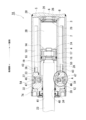
- the shock absorbers 1A to 1D according to the first to fourth embodiments of the present invention will be described in detail with reference to FIGS. 1 to 10.
- the shock absorbers 1A to 1D according to the first to fourth embodiments are dampers for damping rolling of a railway vehicle, and are installed in a substantially horizontal direction and used sideways.
- the upper portion of the piston rod 23 will be referred to as the upper portion and the lower portion will be referred to as the lower portion of the piston rod 23 in the installed state.
- the shock absorber 1A according to the first embodiment will be described with reference to FIGS. 1 to 4.
- the shock absorber 1A according to the first embodiment is provided with cylindrical outer cylinders 3 substantially concentrically on the outer periphery of the cylinder 2.
- An annular reservoir 4 is formed between the cylinder 2 and the outer cylinder 3. That is, the shock absorber 1A according to the first embodiment is formed in a double cylinder structure.
- One end opening of the cylinder 2 and the outer cylinder 3 is closed by the one end side plate 5 and the base member 6. That is, the base member 6 is liquid-tightly fitted by the seal member 8 in the opening at one end of the cylinder 2.
- the one-end side plate 5 is welded to one end of the outer cylinder 3 to close one end opening of the outer cylinder 3.
- the base member 6 is arranged between the one end side plate 5 and one end of the cylinder 2.
- the other end openings of the cylinder 2 and the outer cylinder 3 are closed by the rod guide 12.
- a piston 14 is slidably arranged in the cylinder 2 along the axial direction of the cylinder 2.
- the cylinder chamber 2B is located on one end side, and the cylinder chamber 2A is located on the other end side.
- a seal member 16 and a sleeve 17 are arranged between the outer peripheral surface of the piston 14 and the inner peripheral surface of the cylinder 2.
- the piston 14 is provided with a passage 18 that communicates between the cylinder chambers 2A and 2B.
- the piston 14 is provided with a check valve 19 that allows only the flow of hydraulic oil from the cylinder chamber 2B side to the cylinder chamber 2A side in the passage 18.
- One end of the piston rod 23 is connected to the piston 14 by a nut 24.
- the other end side of the piston rod 23 is slidable and liquid-tightly inserted into the rod guide 12 and extends to the outside.
- the cylinder 2 is filled with hydraulic oil, which is a hydraulic fluid.
- a hydraulic oil and a gas, which are hydraulic fluids, are sealed in the reservoir 4.
- a plurality of passages 26, 26 communicating the cylinder chamber 2B and the reservoir 4 are formed in the base member 6 at intervals in the circumferential direction.
- a valve chamber 28 communicating with the passages 26 and 26 is recessed on the other end surface of the base member 6. In the valve chamber 28, a check valve 29 that allows only the flow of hydraulic oil from the reservoir 4 side to the cylinder chamber 2B side in the passages 26 and 26 is arranged.
- the rod guide 12 is for slidably supporting the piston rod 23 protruding from the other end of the cylinder 2.
- the rod guide 12 is supported inside the other end side of the outer cylinder 3.
- the rod guide 12 is an annular fitting portion that protrudes from one end surface of the cylindrical guide main body 32 and one end surface of the guide main body 32 toward one end side substantially concentrically and is fitted in the reservoir 4.
- the 33 and the cylindrical support portion 34 projecting from the other end surface of the guide main body portion 32 toward the other end side substantially concentrically are integrally connected to each other.
- An annular recess 37 is formed on the inner peripheral surface of the guide main body 32 from one end surface toward the other end. The annular recess 37 communicates with the cylinder chamber 2A.
- a seal member 36 is arranged between the inner peripheral surface of the fitting portion 33 and the outer peripheral surface of the other end of the cylinder 2.
- a sleeve 39 and sealing members 40, 41 are arranged between the inner peripheral surface of the rod guide 12 and the outer peripheral surface of the piston rod 23 on the other end side from the annular recess 37 provided on the inner peripheral surface of the guide main body 32. Has been done.
- the guide main body portion 32 and the fitting portion 33 are provided with passages 43 and 43 for communicating between the cylinder chamber 2A and the reservoir 4, with reference to FIGS. 2 to 4 as appropriate.
- a plurality of the passages 43 are formed at intervals along the circumferential direction, corresponding to the valve chambers 47 described later.
- the cylinder chamber 2A and the upper part of the reservoir 4 are communicated with each other via the passage 43.
- the cylinder chamber 2A and the lower part of the reservoir 4 are communicated with each other via the passage 43.
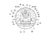
- the passage 43 includes an inflow passage 46, a valve chamber 47, a plurality of discharge ports 48 and 48, discharge passages 49 and 49, and discharge pipes 50 and 50.
- the inflow path 46 opens in the annular recess 37 of the guide main body 32 and extends along the radial direction of the cylinder 2.
- the inflow passage 46 communicates with the valve chamber 47.
- the inflow passage 46 communicates with the valve chamber 47 via the orifice 69 of the valve body 57 at the stage before the valve opening of the damping valve 54, which will be described later.
- the valve chamber 47 is provided in the guide main body 32.
- the valve chamber 47 is formed by a space portion having a substantially circular cross section extending along the radial direction of the cylinder 2.
- the valve chamber 47 is opened by the hydraulic pressure from the cylinder chamber 2A to allow the hydraulic oil to flow from the cylinder chamber 2A to the reservoir 4, and the hydraulic oil to flow from the reservoir 4 to the cylinder chamber 2A.
- a damping valve 54 that regulates and functions as a check valve is arranged.
- the damping valve 54 is a poppet valve type.
- the damping valve 54 includes a valve body 57 that is movably arranged in the valve chamber 47 in a direction along the radial direction of the cylinder 2, a coil spring 58 that urges the valve body 57 toward the inflow path 46, and the coil spring 58.
- a spring support 59 for supporting the end of the cylinder is provided.
- the valve body 57 includes a valve body portion 62 formed in a columnar shape, and a guide portion 63 that protrudes along the axial direction from the axial end portion of the valve body portion 62 and is arranged in the inflow path 46.
- An annular flange portion 64 which projects radially outward from the outer peripheral surface of the valve body portion 62, is provided substantially concentrically with each other.
- the valve body 57 is arranged substantially concentrically with respect to the inner peripheral surface of the valve chamber 47.
- the valve body 57 is movably arranged in the valve chamber 47 along the axial direction thereof.
- the guide portion 63 is formed in a columnar shape having a slit 66 extending in the vertical direction.
- the guide portion 63 is formed to have a smaller diameter than the valve main body portion 62.
- the guide portion 63 is formed with a narrow slit 66 extending in the vertical direction substantially at the center in the radial direction.
- the guide portion 63 is composed of a pair of guide pieces 65, 65 having a substantially semicircular cross section, which are arranged so as to sandwich the slit 66.
- a flow hole 68 is formed at a predetermined depth along the axial direction on the surface of the valve body portion 62 of the damping valve 54, which is opposite to the guide portion 63 side.
- An orifice 69 that communicates the flow hole 68 and the slit 66 of the guide portion 63 is formed in the valve body portion 62 along the axial direction.
- the annular flange portion 64 is an outer peripheral surface of the valve main body portion 62, and is projected outward in the radial direction from a position near the boundary with the guide portion 63.
- the outer diameter of the annular brand portion 64 is smaller than the inner diameter of the valve chamber 47.
- the valve chamber 47 is configured such that the opening on the outer cylinder 3 side is closed by the spring support 59.
- the spring support 59 is formed in a disk shape.
- disk-shaped support portions 72 are provided so as to project toward the valve body 57 side in a substantially concentric manner.
- the support portion 72 is for supporting the coil spring 58 from the inside in the radial direction.
- the outer diameter of the support portion 72 and the outer diameter of the valve body portion 62 of the valve body 57 are substantially the same, and are slightly smaller than the inner diameter of the coil spring 58.
- the guide portion 63 of the valve body 57 is arranged in the inflow passage 46, and the coil spring 58 is arranged between the annular flange portion 64 of the valve body 57 and the peripheral portion of the support portion 72 of the spring support 59. .. As a result, the valve body 57 is urged by the coil spring 58 in the direction of closing the inflow path 46.
- each of the discharge ports 48, 48 is formed on the inner peripheral surface of the valve chamber 47 at intervals along the circumferential direction. Each of the discharge ports 48 and 48 extends along the radial direction of the valve chamber 47. Each of the discharge ports 48 and 48 is formed to have a substantially circular cross section. As shown in FIG. 4, each of the discharge ports 48 and 48 is formed on the inner peripheral surface of the valve chamber 47 at a position symmetrical with respect to the radial center of the inner peripheral surface. In other words, each of the discharge ports 48, 48 is formed on the inner peripheral surface of the valve chamber 47 at a position symmetrical with respect to the radial center of the valve body 57.
- each of the discharge ports 48, 48 is formed on the inner peripheral surface of the valve chamber 47 at a position on a straight line along the radial direction passing through the radial center of the valve chamber 47 (valve body 57).
- each of the discharge ports 48 and 48 is formed on the inner peripheral surface of the valve chamber 47 at positions facing each other.
- the outlets 48, 48 are formed in an even number. The opening areas of the outlets 48 and 48 are substantially the same.
- the discharge ports 48 and 48 are formed at two locations on the inner peripheral surface of the valve chamber 47 at a pitch of 180 ° along the circumferential direction.
- the positions of the discharge ports 48 and 48 along the axial direction of the valve chamber 47 are substantially the same.
- the positions of the discharge ports 48 and 48 along the axial direction of the valve chamber 47 are not specified as long as they are positions other than the range in which the spring support 59 is fixed.
- each of the discharge ports 48 and 48 communicates with the corresponding discharge paths 49 and 49, respectively.
- the discharge passages 49, 49 are formed along the axial direction of the cylinder 2 in a range from the guide main body portion 32 of the rod guide 12 to one end surface of the fitting portion 33.
- the discharge passages 49 and 49 are formed at two locations corresponding to the discharge ports 48 and 48, respectively.
- Each of the discharge pipes 50 and 50 is fitted so that the other end side communicates with the discharge passages 49 and 49 in the rod guide 12, respectively.
- each of the discharge pipes 50 and 50 protrudes from one end surface of the fitting portion 33 of the rod guide 12 into the reservoir 4 along the axial direction.
- One end of each of the discharge pipes 50 and 50 extends to a position in front of the base member 6.
- the valve chamber 47 is formed by a space portion having a substantially circular cross section extending along the radial direction of the cylinder 2, and the discharge ports 48 and 48 are formed on the inner peripheral surface thereof.
- the valve chamber 47 may be formed by a space portion having a polygonal cross section, and the discharge ports 48 and 48 are included in the valve chambers 47.
- a plurality of may be formed on the peripheral surface at point-symmetrical positions with the center of the inner peripheral surface as a point.
- the inner peripheral surface of the valve chamber 47 includes not only a substantially circular shape in a plan view but also an elliptical shape, an oval shape, a polygonal shape, and the like.
- an annular ring 74 on the other end side is arranged around the support portion 34 of the rod guide 12. That is, by arranging the other end side ring 74 in the annular recess around the support portion 34 of the rod guide 12 and screwing it into the other end inner peripheral surface of the outer cylinder 3, the rod guide 12 can be attached to the other of the outer cylinder 3. It is inside the end portion and can be supported between the other end side ring 74 and the other end of the cylinder 2.
- the check valve 19 of the piston 14 is closed by the movement of the piston 14 in the cylinder 2, the hydraulic oil in the cylinder chamber 2A is pressurized, and the passages 43 and 43 of the rod guide 12 are pressed. It flows through to the reservoir 4.
- the check valve 29 of the base member 6 is opened, and a considerable amount of hydraulic oil from which the piston rod 23 has exited from the cylinder 2 is replenished from the reservoir 4 to the cylinder chamber 2B via the passages 26 and 26.
- the discharge ports 48, 48 communicating the valve chamber 47 and the discharge passages 49, 49 are the inner peripheral surfaces of the valve chamber 47, and the discharge ports 48, 48 thereof are the inner peripheral surfaces thereof. They are formed at point-symmetrical positions with the radial center of the inner peripheral surface as a point.
- the generation of a pressure difference between certain regions in the valve chamber 47 can be suppressed, and as a result, the self-excited vibration of the damping valve 54 can be suppressed.
- the disturbance of the damping characteristic due to vibration can be suppressed, and the damping characteristic can be stabilized. Furthermore, uneven wear due to vibration can be suppressed, and the progress of aging deterioration can be delayed as compared with the conventional case.
- the shock absorber 1A according to the first embodiment since the opening areas of the discharge ports 48 and 48 are substantially the same, it is possible to further suppress the occurrence of a pressure difference between certain regions in the valve chamber 47. it can. Further, in the shock absorber 1A according to the first embodiment, since the discharge passages 49 and 49 are formed corresponding to the discharge ports 48 and 48, respectively, the pressure difference between certain regions in the valve chamber 47 Can be further suppressed.
- the above-mentioned structure such as the arrangement of the discharge ports 48 and 48 communicating with the discharge paths 49 and 49 is, for example, a piston 14 or a base member 6 if it is a shock absorber provided with a damping valve mechanism using a poppet valve. It can also be applied to the valve chamber provided inside. Further, this structure can also be applied to a valve chamber including a damping valve without an orifice 69 of the valve body 57.
- the valve chamber 47 is located on the outer cylinder 3 side, and has a large-diameter space portion 80 having a substantially circular cross section extending along the radial direction of the cylinder 2 and the large-diameter space. It is composed of a small-diameter space portion 81 having a diameter smaller than that of the portion 80 and having a substantially circular cross section extending continuously from the large-diameter space portion 80 toward the inflow path 46.
- the large-diameter space portion 80 and the small-diameter space portion 81 are formed substantially concentrically.
- An annular step portion 82 is formed between the large-diameter space portion 80 and the small-diameter space portion 81.
- the spring support 59 is fixed to the end of the large-diameter space portion 80 on the outer cylinder 3 side.
- a discharge path 49 is opened on the inner peripheral surface of the large-diameter space portion 80.
- one discharge channel 49 is formed.
- the discharge path 49 is formed along the axial direction of the cylinder 2 in a range from the guide main body portion 32 of the rod guide 12 to one end surface of the fitting portion 33.
- the discharge path 49 communicates with the discharge pipe 50 fitted to the rod guide 12.
- the discharge ring 85 is arranged substantially concentrically with the inner peripheral surface of the large diameter space portion 80 so as to be in contact with the inner peripheral surface of the large diameter space portion 80 and the annular step portion 82.
- the discharge ring 85 is formed in a U-shaped cross section. Specifically, the discharge ring 85 is valved so that its open side faces the inner peripheral surface of the large-diameter space portion 80 and is in contact with the inner peripheral surface of the large-diameter space portion 80 and the annular step portion 82. It is arranged substantially concentrically with the inner peripheral surface of the chamber 47.
- a plurality of discharge ports 48, 48 are formed in the discharge ring 85. Each of the discharge ports 48 and 48 is formed to have a substantially circular cross section.
- a plurality of the discharge ports 48, 48 are formed at point-symmetrical positions with the radial center of the inner peripheral surface of the discharge ring 85 as a point.
- each of the discharge ports 48, 48 is formed at a position symmetrical with respect to the radial center of the inner peripheral surface of the valve chamber 47 (large diameter space portion 80 and small diameter space portion 81).
- the discharge ports 48 and 48 are formed at two positions at a pitch of 180 ° along the circumferential direction of the discharge ring 85.
- an annular passage 87 is formed between the outer peripheral surface of the discharge ring 85 and the inner peripheral surface of the large-diameter space portion 80 of the valve chamber 47.
- the annular passage 87 communicates with the discharge passage 49.
- the discharge ring 85 is arranged so that the straight line connecting the pair of discharge ports 48, 48 is substantially orthogonal to the discharge path 49.
- the passage 43 communicating the cylinder chamber 2A and the reservoir 4 is annular with the inflow passage 46, the valve chamber 47, and the discharge ports 48 and 48 of the discharge ring 85. It is composed of a passage 87, a discharge path 49, and a discharge pipe 50.
- the hydraulic pressure in the cylinder chamber 2A causes the inside of the valve chamber 47.
- the damping valve 54 is opened, and hydraulic oil flows from the valve chamber 47 of the passage 43 to the reservoir 4 via the discharge ports 48 and 48 of the discharge ring 85, the annular passage 87, the discharge path 49, and the discharge pipe 50.
- the discharge ports 48 and 48 of the discharge ring 85 are formed at point-symmetrical positions with respect to the radial center of the inner peripheral surface of the discharge ring 85 (valve chamber 47), the valve chamber 47 is formed.
- an annular groove 90 having a substantially rectangular cross section extending in the circumferential direction is formed on the inner peripheral surface of the valve chamber 47.
- a C-shaped discharge ring 91 is arranged substantially concentrically with the inner peripheral surface of the valve chamber 47 so as to close the annular groove 90.
- the discharge ring 91 is arranged so that one end surface in the axial direction abuts on the bottom surface of the valve chamber 47, that is, the surface opposite to the spring support 59 side.
- the C-shaped discharge ring 91 has a slit portion 92, and a discharge port 48 is formed at a position facing the slit portion 92.
- the slit portion (discharge port) 92 and the discharge port 48 are formed at point-symmetrical positions with respect to the radial center of the inner peripheral surface of the discharge ring 91, respectively.
- the slit portion (discharge port) 92 and the discharge port 48 are formed at point-symmetrical positions with respect to the radial center of the inner peripheral surface of the valve chamber 47, respectively.
- the discharge port 48 is formed to have a substantially circular cross section. It is preferable that the opening area of the slit portion 92 and the opening area of the discharge port 48 are substantially the same.
- the discharge ring 91 When the discharge ring 91 is arranged substantially concentrically with the inner peripheral surface of the valve chamber 47 so as to close the annular groove 90 provided on the inner peripheral surface of the valve chamber 47, the outer peripheral surface of the discharge ring 91 and the valve chamber are arranged.
- An annular passage 94 is formed between the annular groove 90 and the annular groove 90 provided on the inner peripheral surface of the 47.
- the annular passage 94 communicates with the discharge passage 49.
- the discharge ring 91 is arranged so that the straight line connecting the slit portion 92 and the discharge port 48 is substantially orthogonal to the discharge path 49.
- the passage 43 communicating the cylinder chamber 2A and the reservoir 4 includes an inflow passage 46, a valve chamber 47, a slit portion 92 of the discharge ring 91, and a discharge port 48. It is composed of an annular passage 94, a discharge passage 49, and a discharge pipe 50.
- the valve chamber 47 due to the hydraulic pressure in the cylinder chamber 2A.
- the damping valve 54 inside opens, and hydraulic oil flows from the inside of the valve chamber 47 of the passage 43 to the reservoir 4 via the slit portion 92 and the discharge port 48 of the discharge ring 91, the annular passage 94, the discharge passage 49, and the discharge pipe 50. It flows.
- the slit portion 92 and the discharge port 48 of the discharge ring 91 are formed at point-symmetrical positions with respect to the radial center of the inner peripheral surface of the discharge ring 91 (valve chamber 47), respectively.
- the discharge port 48 is formed of a substantially circular hole, but as the discharge port 48, a groove is formed on one end surface or the other end surface in the axial direction of the discharge ring 91. May be adopted.
- an annular step in which the inner diameter of the valve chamber 47 is different so as to be continuous with the wall surface on the cylinder 2 side of the wall surfaces facing the annular groove 90. Part 95 is provided.
- one end surface of the discharge ring 91 in the axial direction may be arranged so as to be in contact with the annular step portion 95 so as to close the annular groove portion 90 provided on the inner peripheral surface of the valve chamber 47.
- the shock absorber 1D according to the fourth embodiment will be described with reference to FIG.
- the differences from the shock absorber 1A according to the first embodiment will be mainly described.
- a plurality of discharge ports 48, 48 provided on the inner peripheral surface of the valve chamber 47 are provided in the radial direction of the valve chamber 47. It does not extend along the line, and by interfering the valve chamber 47 with the ends of the discharge passages 49 and 49, the interference portions are opened to form the discharge ports 48 and 48, respectively. Since the positions of the discharge ports 48 and 48 and their effects are the same as those of the shock absorber 1A according to the first embodiment, the description thereof will be omitted here.
- the above embodiment describes a case where the present invention is applied to a so-called uniflow type shock absorber in which hydraulic oil flows in one direction from the cylinder chamber 2A to the reservoir 4 through the passage 43 during the expansion / contraction stroke of the piston rod 23.
- the present invention can be applied to other types of shock absorbers as well. Can be applied. Further, it can be applied not only to a shock absorber installed in a substantially horizontal direction and used in a horizontal direction, but also to a shock absorber used in a vertical direction or tilted.
- the present invention is not limited to the above-described embodiment, and includes various modifications.
- the above-described embodiment has been described in detail in order to explain the present invention in an easy-to-understand manner, and is not necessarily limited to the one including all the described configurations.
- it is possible to replace a part of the configuration of one embodiment with the configuration of another embodiment and it is also possible to add the configuration of another embodiment to the configuration of one embodiment.
- 1A, 1B, 1C, 1D shock absorber 2 cylinder, 2A, 2B cylinder chamber, 3 outer cylinder, 4 reservoir, 14 piston, 23 piston rod, 43 passage, 47 valve chamber, 48 discharge port, 49 discharge path, 54 attenuation valve
Landscapes
- Engineering & Computer Science (AREA)
- General Engineering & Computer Science (AREA)
- Mechanical Engineering (AREA)
- Fluid-Damping Devices (AREA)
Priority Applications (3)
| Application Number | Priority Date | Filing Date | Title |
|---|---|---|---|
| EP20897181.2A EP4071379A4 (en) | 2019-12-06 | 2020-12-03 | SHOCK ABSORBER |
| CN202080084060.XA CN114761700A (zh) | 2019-12-06 | 2020-12-03 | 缓冲器 |
| JP2021562718A JP7209866B2 (ja) | 2019-12-06 | 2020-12-03 | 緩衝器 |
Applications Claiming Priority (2)
| Application Number | Priority Date | Filing Date | Title |
|---|---|---|---|
| JP2019-221115 | 2019-12-06 | ||
| JP2019221115 | 2019-12-06 |
Publications (1)
| Publication Number | Publication Date |
|---|---|
| WO2021112180A1 true WO2021112180A1 (ja) | 2021-06-10 |
Family
ID=76222433
Family Applications (1)
| Application Number | Title | Priority Date | Filing Date |
|---|---|---|---|
| PCT/JP2020/045050 Ceased WO2021112180A1 (ja) | 2019-12-06 | 2020-12-03 | 緩衝器 |
Country Status (4)
| Country | Link |
|---|---|
| EP (1) | EP4071379A4 (https=) |
| JP (1) | JP7209866B2 (https=) |
| CN (1) | CN114761700A (https=) |
| WO (1) | WO2021112180A1 (https=) |
Citations (5)
| Publication number | Priority date | Publication date | Assignee | Title |
|---|---|---|---|---|
| JP2005291409A (ja) * | 2004-04-01 | 2005-10-20 | Tokyo Gas Co Ltd | 逆止弁 |
| JP2009287609A (ja) * | 2008-05-27 | 2009-12-10 | Hitachi Automotive Systems Ltd | 流体圧緩衝器 |
| JP2013015157A (ja) * | 2011-06-30 | 2013-01-24 | Hitachi Automotive Systems Ltd | 流体圧緩衝器 |
| JP2015048873A (ja) | 2013-08-30 | 2015-03-16 | 日立オートモティブシステムズ株式会社 | 緩衝器 |
| JP2019221115A (ja) | 2018-06-22 | 2019-12-26 | 株式会社東芝 | 走行状況提示装置 |
Family Cites Families (8)
| Publication number | Priority date | Publication date | Assignee | Title |
|---|---|---|---|---|
| JPH05180261A (ja) * | 1991-12-27 | 1993-07-20 | Kayaba Ind Co Ltd | 減衰力可変型ダンパ |
| JP4141077B2 (ja) * | 2000-03-01 | 2008-08-27 | カヤバ工業株式会社 | リリーフ弁 |
| JP5424166B2 (ja) * | 2009-06-26 | 2014-02-26 | 日立オートモティブシステムズ株式会社 | 横置きシリンダ装置 |
| JP5369058B2 (ja) * | 2010-06-30 | 2013-12-18 | カヤバ工業株式会社 | 減衰バルブ |
| TWI448630B (zh) * | 2010-06-30 | 2014-08-11 | Kayaba Industry Co Ltd | Decay valve |
| JP6489977B2 (ja) * | 2015-08-31 | 2019-03-27 | 日立オートモティブシステムズ株式会社 | 緩衝器 |
| JP2019143642A (ja) * | 2016-06-27 | 2019-08-29 | 日立オートモティブシステムズ株式会社 | 緩衝器 |
| JP6701242B2 (ja) * | 2018-02-21 | 2020-05-27 | Kyb株式会社 | バルブおよび緩衝器 |
-
2020
- 2020-12-03 EP EP20897181.2A patent/EP4071379A4/en not_active Withdrawn
- 2020-12-03 CN CN202080084060.XA patent/CN114761700A/zh active Pending
- 2020-12-03 JP JP2021562718A patent/JP7209866B2/ja active Active
- 2020-12-03 WO PCT/JP2020/045050 patent/WO2021112180A1/ja not_active Ceased
Patent Citations (5)
| Publication number | Priority date | Publication date | Assignee | Title |
|---|---|---|---|---|
| JP2005291409A (ja) * | 2004-04-01 | 2005-10-20 | Tokyo Gas Co Ltd | 逆止弁 |
| JP2009287609A (ja) * | 2008-05-27 | 2009-12-10 | Hitachi Automotive Systems Ltd | 流体圧緩衝器 |
| JP2013015157A (ja) * | 2011-06-30 | 2013-01-24 | Hitachi Automotive Systems Ltd | 流体圧緩衝器 |
| JP2015048873A (ja) | 2013-08-30 | 2015-03-16 | 日立オートモティブシステムズ株式会社 | 緩衝器 |
| JP2019221115A (ja) | 2018-06-22 | 2019-12-26 | 株式会社東芝 | 走行状況提示装置 |
Non-Patent Citations (1)
| Title |
|---|
| See also references of EP4071379A1 |
Also Published As
| Publication number | Publication date |
|---|---|
| EP4071379A1 (en) | 2022-10-12 |
| JPWO2021112180A1 (https=) | 2021-06-10 |
| JP7209866B2 (ja) | 2023-01-20 |
| EP4071379A4 (en) | 2023-03-01 |
| CN114761700A (zh) | 2022-07-15 |
Similar Documents
| Publication | Publication Date | Title |
|---|---|---|
| CN104334912B (zh) | 缓冲器的阻尼阀 | |
| KR101773238B1 (ko) | 완충기의 감쇠 밸브 | |
| JP6465983B2 (ja) | 緩衝器 | |
| JP7109293B2 (ja) | 緩衝器 | |
| JP6972352B2 (ja) | 緩衝器 | |
| JP7118169B2 (ja) | 緩衝器 | |
| US20200256417A1 (en) | Valve and shock absorber | |
| JP6863667B2 (ja) | 緩衝器 | |
| JP6114499B2 (ja) | シール部材および緩衝器 | |
| WO2021112180A1 (ja) | 緩衝器 | |
| WO2017022494A1 (ja) | シリンダ装置 | |
| JP2009287719A (ja) | 油圧緩衝器 | |
| KR20230116934A (ko) | 완충기 | |
| WO2016194548A1 (ja) | 緩衝器 | |
| JP2014199092A (ja) | 緩衝器 | |
| JP2017096453A (ja) | 緩衝器 | |
| JP6014459B2 (ja) | シリンダ装置 | |
| JP5064298B2 (ja) | 液圧緩衝器 | |
| JP7584396B2 (ja) | 緩衝器 | |
| JP2018105385A (ja) | 緩衝器 | |
| JP7154199B2 (ja) | 緩衝器 | |
| CN121511365A (zh) | 缓冲器 | |
| JP2024154268A (ja) | 緩衝器 | |
| JP2008180292A (ja) | 緩衝器 | |
| JP2025180713A (ja) | 緩衝器 |
Legal Events
| Date | Code | Title | Description |
|---|---|---|---|
| 121 | Ep: the epo has been informed by wipo that ep was designated in this application |
Ref document number: 20897181 Country of ref document: EP Kind code of ref document: A1 |
|
| ENP | Entry into the national phase |
Ref document number: 2021562718 Country of ref document: JP Kind code of ref document: A |
|
| NENP | Non-entry into the national phase |
Ref country code: DE |
|
| ENP | Entry into the national phase |
Ref document number: 2020897181 Country of ref document: EP Effective date: 20220706 |