WO2021111984A1 - 回路構成体 - Google Patents
回路構成体 Download PDFInfo
- Publication number
- WO2021111984A1 WO2021111984A1 PCT/JP2020/044063 JP2020044063W WO2021111984A1 WO 2021111984 A1 WO2021111984 A1 WO 2021111984A1 JP 2020044063 W JP2020044063 W JP 2020044063W WO 2021111984 A1 WO2021111984 A1 WO 2021111984A1
- Authority
- WO
- WIPO (PCT)
- Prior art keywords
- circuit configuration
- relay
- refrigerant
- cooling component
- cooling
- Prior art date
- Legal status (The legal status is an assumption and is not a legal conclusion. Google has not performed a legal analysis and makes no representation as to the accuracy of the status listed.)
- Ceased
Links
Images




Classifications
-
- H—ELECTRICITY
- H02—GENERATION; CONVERSION OR DISTRIBUTION OF ELECTRIC POWER
- H02G—INSTALLATION OF ELECTRIC CABLES OR LINES, OR OF COMBINED OPTICAL AND ELECTRIC CABLES OR LINES
- H02G3/00—Installations of electric cables or lines or protective tubing therefor in or on buildings, equivalent structures or vehicles
- H02G3/02—Details
- H02G3/03—Cooling
-
- H—ELECTRICITY
- H05—ELECTRIC TECHNIQUES NOT OTHERWISE PROVIDED FOR
- H05K—PRINTED CIRCUITS; CASINGS OR CONSTRUCTIONAL DETAILS OF ELECTRIC APPARATUS; MANUFACTURE OF ASSEMBLAGES OF ELECTRICAL COMPONENTS
- H05K7/00—Constructional details common to different types of electric apparatus
- H05K7/20—Modifications to facilitate cooling, ventilating, or heating
- H05K7/20218—Modifications to facilitate cooling, ventilating, or heating using a liquid coolant without phase change in electronic enclosures
- H05K7/20272—Accessories for moving fluid, for expanding fluid, for connecting fluid conduits, for distributing fluid, for removing gas or for preventing leakage, e.g. pumps, tanks or manifolds
-
- H—ELECTRICITY
- H02—GENERATION; CONVERSION OR DISTRIBUTION OF ELECTRIC POWER
- H02G—INSTALLATION OF ELECTRIC CABLES OR LINES, OR OF COMBINED OPTICAL AND ELECTRIC CABLES OR LINES
- H02G3/00—Installations of electric cables or lines or protective tubing therefor in or on buildings, equivalent structures or vehicles
- H02G3/02—Details
- H02G3/08—Distribution boxes; Connection or junction boxes
- H02G3/16—Distribution boxes; Connection or junction boxes structurally associated with support for line-connecting terminals within the box
Definitions
- This disclosure relates to a circuit configuration including heat generating parts.
- Patent Document 1 discloses a circuit configuration including a relay that interrupts and interrupts the power supply of a battery to a motor or a generator connected via an inverter as a load on the vehicle side.
- the circuit configuration of the present disclosure includes a heat-generating component that generates heat by energization, an energizing member connected to a connection portion of the heat-generating component, and a cooling component in which a refrigerant is circulated inside and is thermally contacted with the energizing member. It is a circuit configuration including.
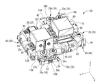
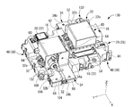
- FIG. 1 is a perspective view of a circuit configuration according to the first embodiment.
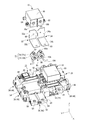
- FIG. 2 is an exploded perspective view of the circuit configuration shown in FIG.
- FIG. 3 is a diagram schematically showing an electrical configuration in a path from a power source to a load in the circuit configuration shown in FIG.
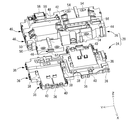
- FIG. 4 is an exploded perspective view of a base member constituting the circuit configuration shown in FIG.
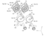
- FIG. 5 is an exploded perspective view of the cooling components constituting the circuit configuration shown in FIG.
- FIG. 6 is an exploded perspective view showing the cooling component shown in FIG. 5 from another direction.
- FIG. 7 is a perspective view of the circuit configuration according to the second embodiment.
- FIG. 8 is a perspective view of the circuit configuration according to the third embodiment.
- FIG. 9 is a perspective view of the circuit configuration according to the fourth embodiment.
- the circuit configuration of the present disclosure is (1) A circuit configuration including a heat-generating component that generates heat by energization, an energizing member connected to a connection portion of the heat-generating component, and a cooling component in which a refrigerant is circulated inside and is thermally contacted with the energizing member. is there.
- the cooling component through which the refrigerant flows is in thermal contact with the energizing member directly connected to the connecting portion which is the heat generating portion of the heat generating component. Therefore, the energizing member to which the heat of the heat-generating component is transferred can be positively cooled by the cooling component, and the heat-dissipating path of the heat-generating component is promoted more reliably by a shorter heat transfer path as compared with the conventional structure. The heat dissipation performance can be improved.
- the chassis and the housing itself to which the energizing member such as the bus bar is thermally contacted are at a high temperature exceeding 70 ° C. Compared with the conventional structure, the heat dissipation effect and the cooling effect can be improved.
- the refrigerant flowing through the refrigerant flow path can be any refrigerant that can be used in the vehicle, such as a radiator liquid.
- the thermal contact of the cooling component with the energizing member includes a mode in which the cooling component is directly contacted with the energizing member or indirectly contacted with another member having high thermal conductivity.
- the energizing member is connected to the connecting portion of the heat generating component, the heat of the heat generating component is advantageously transferred, but the energizing member connected to the connecting portion of the heat generating component is of the heat generating component.
- Heat-generating parts include parts that generate heat when energized, such as relays and fuses.
- the cooling component is fastened to the connection portion of the heat generating component via the current-carrying member. Since the cooling component is fastened to the connection part, which is the heat generating part of the heat generating part, together with the energizing member, the separation distance between the heat generating part and the heat radiating part can be almost eliminated, and the heat radiating of the heat generating part can be realized more efficiently. Because it can be done.
- the cooling component has a refrigerant flow path provided with an inlet and an outlet for the refrigerant, and an external refrigerant supply path and a refrigerant discharge path can be connected to the inlet and the outlet.
- An external refrigerant supply / discharge path can be easily connected to the inlet and outlet of the refrigerant flow path provided in the cooling component, and the circulation of the refrigerant in the refrigerant flow path of the cooling component can be easily realized. Because it can be done.
- the cooling component has an annular cylinder body, the inner hole of the annular cylinder body is a fastening component insertion hole, and the annular cylinder bodies are assembled to each other in the axial direction.
- the first part includes an annular first part and an annular second part, the first part has a concave first-flow passage forming portion that opens to an assembly surface to the second part, and the second part is the first part. It has a concave second flow passage forming portion that opens to the assembly surface to one part, and the first part and the second part are in close contact with each other via a sealing member. It is preferable that the refrigerant flow path partitioned by the first flow passage forming portion and the second flow passage forming portion is formed inside the annular cylinder body by being assembled and fixed to each other.
- the fastener insertion hole through which the fastener can be inserted is configured by using the inner hole of the annular cylinder body, and it is possible to provide a compact cooling component that can be fastened by the fastener.
- the refrigerant flow path can be made by bringing the first flow passage forming portion and the second flow passage forming portion that open to each assembly surface of the annular first / second parts close to each other via the sealing member. Since it is partitioned, the cooling component can be formed by a simple molding mold structure.
- one of the first part and the second part in contact with the energizing member is made of a material having higher thermal conductivity than the other part. .. This is because by improving the thermal conductivity of one part in contact with the current-carrying member, it is possible to efficiently improve the heat transfer performance of the cooling part and reduce the cost of the other part.
- the cooling component is fixed to the energizing member in a contact state by using a bolt, and the cooling component has a rotation blocking protrusion that abuts on another member to prevent the cooling component from rotating. It is preferable to do.
- the rotation blocking protrusion of the cooling component comes into contact with another member, excessive rotation of the cooling component can be prevented, so that the bolt can be advantageously fastened between the cooling component and the energizing member.
- the circuit configuration 10 is mounted on a vehicle (not shown) such as an electric vehicle or a hybrid vehicle, and supplies and controls electric power from a power source 12 such as a battery to a load 14 such as a motor (see FIG. 3).
- a power source 12 such as a battery
- a load 14 such as a motor
- the orientation of the circuit configuration 10 when mounted on the vehicle is not limited, but in the following description, the upward direction is the Z direction in FIG. 1, and the front direction is the X direction and the left direction in FIG. Will be described as the Y direction in FIG.
- a reference numeral may be added to only a part of the members, and the reference numeral may be omitted for the other members.
- the circuit configuration 10 includes a circuit configuration 10a provided on the positive electrode side and a circuit configuration 10b provided on the negative electrode side.
- the positive electrode side of the power supply 12 is connected to the input side of the circuit configuration 10a, and the negative electrode side of the power supply 12 is connected to the input side of the circuit configuration 10b.
- the positive electrode side of the load 14 is connected to the output side of the circuit configuration 10a, and the negative electrode side of the load 14 is connected to the output side of the circuit configuration 10b.
- a relay 16 which is a heat generating component for connecting the power supply 12 to the load 14 is connected between the input side and the output side of the circuit structure 10a and the circuit structure 10b, respectively.
- a precharge circuit 22 in which the precharge resistor 18 and the precharge relay 20 are connected in series so as to bypass the relay 16 is connected to the relay 16 that connects the power supply 12 and the positive electrode side of the load 14. ..
- the precharge resistor 18 is connected to the input side of the precharge relay 20.
- the precharge circuit 22 is similarly connected to the relay 16 connecting the power supply 12 and the negative electrode side of the load 14, but in FIG. 3, the precharge circuit 22 is connected to the relay 16 connecting the power supply 12 and the negative electrode side of the load 14.
- the charge circuit 22 is shown by a chain double-dashed line.
- both the relay 16 and the precharge relay 20 are relays that move the contact portion to switch the contact portion ON / OFF while the exciting coil is energized, and ON / OFF control is performed by a control circuit (not shown). ..
- the circuit structure 10a and the circuit structure 10b have substantially the same structure.
- the circuit configuration 10 includes a lower case 24 located below and an upper case 26 located above when mounted on a vehicle.
- the lower case 24 and the upper case 26 constitute an insulating base member 28.
- a bus bar that connects the relay 16 and the precharge circuit 22 and a bus bar that connects the inside of the precharge circuit 22 are housed.
- the base member 28 is provided with two relays 16 and bus bars 32 and 34 as energizing members connected to the connecting portions 30a and 30b of the respective relays 16.
- the lower case 24 is formed by injection molding an insulating synthetic resin into a predetermined shape.
- the synthetic resin constituting the lower case 24 may contain a filler such as glass fiber.
- the lower case 24 has a horizontally long flat shape as a whole (the width dimension in the left-right direction is larger than the width dimension in the front-rear direction).
- a plurality of lower side engaging portions 36 are provided on the outer peripheral surface of the lower case 24.
- the lower side engaging portion 36 engages with the upper side engaging portion 46 provided on the outer peripheral surface of the upper case 26, which will be described later, so that the lower case 24 and the upper case 26 are mutually fixed. ..
- the engagement mode between the lower side engaging portion 36 and the upper side engaging portion 46 is not limited, and for example, uneven fitting or the like can be adopted.
- a relay fixing portion 38 having a substantially square cylinder shape to which the legs 63 of the relays 16 and 16 described later are bolted is provided so as to project upward.
- a bolt insertion portion 40 for connecting an electric wire or the like to the relay 16, the precharge resistor 18, the precharge relay 20, or the like is provided on the upper surface of the lower case 24 . That is, the electric wire and the relay 16 and the like can be electrically connected by inserting the bolt into the bolt insertion portion 40 in a state where the terminal portion provided at the end of the electric wire and the upper case 26 are overlapped with each other.
- a plurality of bolt insertion portions 40 are provided in a substantially square tubular shape.
- the upper case 26 is formed by injection molding an insulating synthetic resin into a predetermined shape.
- the synthetic resin constituting the upper case 26 may contain a filler such as glass fiber.
- the upper case 26 has a substantially box-like shape that opens downward as a whole, and is provided with an upper wall 42 having a shape substantially similar to that of the lower case 24 and a peripheral wall 44 that protrudes downward from the upper wall 42. ing.
- an upper-side engaging portion 46 is provided at a position corresponding to the lower-side engaging portion 36 in the lower case 24 so that the lower-side engaging portion 36 can be engaged with the lower-side engaging portion 36.
- the upper case 26 is formed with a storage recess 48 in which the relay 16 is housed.
- the accommodating recess 48 in which the relay 16 on the positive electrode side is accommodated and the accommodating recess 48 in which the relay 16 on the negative electrode side is accommodated are provided so as to be separated from each other in the left-right direction.
- the bottom surface of the accommodating recess 48 is a substantially flat surface extending on a horizontal plane (a plane extending in a direction orthogonal to the vertical direction), and is provided at a position lower than the upper wall 42.
- mounting surfaces 50 and 50 on which the bus bars 32 and 34 are mounted are provided in front of the storage recess 48 on the left side and behind the storage recess 48 on the right side.
- the mounting surfaces 50 and 50 are provided at positions lower than the bottom surface of the accommodating recess 48.
- a partition wall portion 52 projecting in the vertical direction is formed between the mounting surfaces 50 and 50.
- a through hole 54 penetrating in the vertical direction is formed at a position corresponding to the relay fixing portion 38 and the bolt insertion portion 40 in the lower case 24.
- the upper wall 42 is provided with a precharge resistor mounting portion 56 for mounting the precharge resistor 18 and a precharge relay mounting portion 58 for mounting the precharge relay 20 with an opening upward.
- the relay 16 is a mechanical relay, and ON / OFF control is performed by a control circuit (not shown).
- the relay 16 includes a relay main body 60 having a substantially hollow rectangular parallelepiped shape as a whole, and has a contact portion and a coil portion (not shown) inside the relay main body 60. ..
- the relay 16 on the left side and the relay 16 on the right side have the same structure, and are mounted in a front-rear inverted state. In the following description, the relay 16 on the left side will be described, and the description of the relay 16 on the right side will be omitted. Further, a pair of through holes are formed on the front end surface of the relay main body 60 so as to be separated from each other in the left-right direction, and these through holes form the connection portions 30a and 30b of the relay 16 described above.
- connection portions 30a and 30b When energized, a current flows between the connection portions 30a and 30b via the contact portion of the relay 16, so that heat is generated at the contact portion.
- a partition plate portion 62 projecting forward is formed between the connecting portions 30a and 30b over substantially the entire length of the relay main body 60 in the vertical direction.
- the relay body 60 is provided with a plurality of legs 63 (three in the present embodiment) protruding from both sides in the left-right direction, and the legs 63 are formed with bolt insertion holes.
- the relay 16 is attached to the base member 28 by inserting and fastening the fixing bolt 64 in a state where the through hole 54 provided in the bottom surface of the accommodating recess 48 in the base member 28 and the bolt insertion hole of the leg portion 63 are aligned. It is attached.
- bus bars 32 and 34 are formed by processing a metal plate material, each of which has conductivity. As shown in FIG. 2, each of the bus bars 32 and 34 is formed by bending into a substantially L shape. One side with respect to the bent portion is a substantially rectangular plate-shaped first connecting portion 32a, 34a connected to the connecting portions 30a, 30b of the relay 16. The first connecting portions 32a and 34a have bolt insertion holes 66 penetrating in the front-rear direction, which is the plate thickness direction. The bus bars 32 and 34 are bolted to the connection portions 30a and 30b of the relay 16 so as to be electrically and thermally connected to the connection portions 30a and 30b of the relay 16.
- each of the bus bars 32 and 34 the other side with respect to the bent portion extends forward, and the extended portion is a second connecting portion 32b and 34b having a substantially rectangular plate shape.
- the second connecting portions 32b and 34b have bolt insertion holes 68 penetrating in the vertical direction, which is the plate thickness direction. These bolt insertion holes 68 are aligned with the through holes 54 provided in the mounting surface 50 when the bus bars 32 and 34 are mounted on the mounting surfaces 50 and 50 of the base member 28. There is.
- the electric wire and the bus bar 32 are fastened by superimposing the terminal portions at the ends of the electric wires (not shown) on the second connecting portions 32b and 34b of the bus bars 32 and 34, and inserting and fastening the bolts through the bolt insertion holes 68 and the through holes 54. , 34 are electrically connected.
- the cooling components 70 as shown in FIGS. 5 and 6 are in thermal contact with the bus bars 32 and 34.
- the cooling component 70 of the first embodiment has a cylindrical shape extending in the front-rear direction as a whole, and includes an annular cylinder main body 72 and an inner hole 74 penetrating the inner peripheral side of the annular cylinder main body 72 in the front-rear direction. There is.
- a pair of cooling parts 70, 70 are provided. That is, the first cooling component 70a is attached to the + side connection portion 30a of the relay 16, and the second cooling component 70b is attached to the ⁇ side connection portion 30b of the relay 16. ..
- the first cooling component 70a and the second cooling component 70b have the same structure. Therefore, in the following description, the first cooling component 70a will be described and the second cooling component 70a will be described. The description of the component 70b will be omitted.
- the annular cylinder body 72 of the first cooling component 70a is configured to include a first part 76 and a second part 78 that are connected to each other in the front-rear direction (the central axis direction of the annular cylinder body 72).
- the first part 76 and the second part 78 are assembled so as to overlap the end faces in the front-rear direction. That is, the front end surface of the first part 76 is the assembly surface 79a to the second part 78, and the rear end surface of the second part 78 is the assembly surface 79b to the first part 76.
- the annular cylinder body 72 and the inner hole 74 are separable in the front-rear direction
- the first part 76 is the first annular cylinder body 72a and the first annular cylinder body 72a constituting the rear portion of the annular cylinder body 72 and the inner hole 74. It is provided with a first inner hole 74a.
- the second part 78 includes a second annular cylinder main body 72b and a second inner hole 74b that form a front portion of the annular cylinder main body 72 and the inner hole 74.
- the first part 76 has a substantially bottomed cylinder shape as a whole, and the first annular cylinder main body 72a is provided so as to project forward from the first bottom wall portion 80a having a substantially disk shape.
- the first annular cylinder main body 72a is integrally formed with protrusions 82 and 82 protruding from both sides in the vertical direction.
- the protruding portion 82 has a semicircular or circular cross section, and extends over substantially the entire length of the first part 76 in the front-rear direction. Then, in the first part 76, the outer peripheral surface of the protruding portion 82 and the outer peripheral surface of the non-formed portion of the protruding portion 82 are continuous with a smooth curved surface.
- the protrusion 82 is provided with a bolt hole 83 that opens forward. Further, the shape of the first bottom wall portion 80a substantially corresponds to the shape of the first annular cylinder body 72a, and the width dimension in the vertical direction is larger than the width dimension in the left-right direction, and the width dimension in the vertical direction is larger. Protruding portions 84 and 84 are formed on both sides.
- the radial intermediate portion of the first part 76 has a concave portion that opens to the front end surface (assembly surface 79a).
- the concave portion is an arc-shaped concave portion 85 extending in the circumferential direction.
- it extends with a circumferential dimension of about one circumference. That is, in the first embodiment, the first inner cylinder portion 86a is provided on the inner peripheral side of the first annular cylinder main body 72a, separated in the radial direction.
- a first inner hole 74a is formed on the inner peripheral side of the first inner cylinder portion 86a, and an arc-shaped recess is formed between the first annular cylinder main body 72a and the first inner cylinder portion 86a in the radial direction. 85 is formed.
- the first part 76 has a double tubular structure including a first annular tubular body 72a and a first inner tubular portion 86a, and has a first annular tubular body 72a and a first annular cylinder body 72a on a part of the circumference.
- One inner cylinder portion 86a is connected to each other.
- the second part 78 has a substantially bottomed cylinder shape as a whole, and a second annular cylinder main body 72b is provided so as to project rearward from the second bottom wall portion 80b having a substantially disk shape. There is.
- the second annular cylinder body 72b is integrally formed with protruding portions 88 projecting on both sides in the vertical direction.
- the protruding portion 88 has an outer shape similar to that of the protruding portion 82 in the first part 76.
- the protruding portion 88 does not extend to the total length in the front-rear direction of the second part 78, and is provided at the rear end portion of the second part 78. Then, a bolt hole 90 is formed by penetrating the protruding portion 88 in the front-rear direction.
- the radial intermediate portion of the second part 78 has a concave portion that opens to the rear end surface (assembly surface 79b).
- the concave portion is an arc-shaped concave portion 92 extending in the circumferential direction.
- it extends with a circumferential dimension of about one circumference. That is, in the first embodiment, the second inner cylinder portion 86b is provided on the inner peripheral side of the second annular cylinder main body 72b, separated in the radial direction.
- a second inner hole 74b is formed on the inner peripheral side of the second inner cylinder portion 86b, and an arc-shaped recess is formed between the second annular cylinder main body 72b and the second inner cylinder portion 86b in the radial direction. 92 is formed.
- the second part 78 has a double tubular structure including a second annular tubular body 72b and a second inner tubular portion 86b, and has a second annular tubular body 72b and a second annular cylinder body 72b on a part of the circumference.
- the second inner cylinder portion 86b is connected to each other.
- the protruding portion 82 of the first part 76 and the protruding portion 88 of the second part 78 are also overlapped.
- the bolt hole 83 and the bolt hole 90 communicate with each other.
- the first part 76 and the second part 78 are connected in the front-rear direction by inserting and fastening the fixing bolt 94 from the front through the bolt hole 83 and the bolt hole 90.
- the first annular cylinder main body 72a and the second annular cylinder main body 72b form a continuous annular cylinder main body 72, and the first inner hole 74a and the second inner hole 74b communicate with each other.
- the inner hole 74 is formed. Further, the arcuate recess 85 in the first part 76 and the arcuate recess 92 in the second part 78 communicate with each other in the front-rear direction. The region partitioned by the two arcuate recesses 85 and 92 is the refrigerant flow path 95 through which the refrigerant flows.
- the refrigerant flowing through the refrigerant flow path 95 can be any refrigerant that can be used in the vehicle, such as a radiator liquid.
- the rear end surfaces of the first annular cylinder body 72a and the first inner cylinder portion 86a and the front end surfaces of the second annular cylinder main body 72b and the second inner cylinder portion 86b are overlapped with each other. It has become.
- An O-ring 96 as a sealing member is provided between these overlapping surfaces.
- an outer peripheral side O-ring 96a is provided between the first and second annular cylinder main bodies 72a and 72b, and between the first inner cylinder portion 86a and the second inner cylinder portion 86b.
- the inner peripheral side O-ring 96b is provided.
- the outer and inner O-rings 96a and 96b are compressed in the front-rear direction, so that the assembling surfaces 79a and 79b of the first part 76 and the second part 78 are assembled. Are in close contact with each other to prevent the refrigerant from leaking.
- the first cooling component 70a and the second cooling component 70b having the above structure are provided one on each of the left and right sides of the relay 16. Then, the first cooling component 70a and the second cooling component 70b that are adjacent to each other in the left-right direction are communicated with each other by the tube 98.
- through holes 100 penetrating in the thickness direction are formed in both first annular cylinder bodies 72a and 72a adjacent to each other in the left-right direction.
- through holes 102 penetrating in the thickness direction are formed in both second annular cylinder bodies 72b and 72b adjacent to each other in the left-right direction.
- the tube 104 extending outward is fixed to the opening edge of the through hole 102 by adhesion, welding, or the like, so that both arcuate recesses 92 and 92 (that is, both refrigerant flow paths 95 and 95) pass through the tube 104, respectively. It is communicated to the external space.
- one through hole 102 is used as an inflow port for the refrigerant into the refrigerant flow path 95, and the other through hole 102 is used as an outflow port from the refrigerant flow path 95.
- the tube 104 connected to one of the through holes 102 is used as a refrigerant supply path for supplying the refrigerant from the outside to the refrigerant flow path 95.
- the tube 104 connected to the other through hole 102 (outlet) is used as a refrigerant discharge path for discharging the refrigerant from the refrigerant flow path 95 to the outside.
- the first flow passage forming portion which is opened in the assembling surface 79a to the second part 78 in the first part 76 and forms a part of the refrigerant flow path 95 is formed by the arc-shaped recess 85.
- the second flow passage forming portion that opens to the assembly surface 79b to the first part 76 and forms a part of the refrigerant flow path 95 is formed by the arc-shaped recess 92.
- the cooling parts (first part 76 and second part 78) as described above can be suitably formed by, for example, a hard synthetic resin. Further, of the first part 76 and the second part 78, the one that comes into contact with the bus bars 32 and 34, which are energizing members (the first part 76 in the first embodiment), is preferably a material having high thermal conductivity.
- the lower case 24 and the upper case 26 constituting the base member 28 are prepared.
- a bus bar that connects the relay 16 and the precharge circuit 22 and a bus bar that connects the inside of the precharge circuit 22 are accommodated and arranged with respect to the lower case 24 or the upper case 26.
- the upper case 26 is superposed on the lower case 24 from above, and the lower side engaging portion 36 and the upper side engaging portion 46 are engaged with each other. As a result, the lower case 24 and the upper case 26 are assembled to form the base member 28.
- the relay 16 is arranged in the accommodating recess 48 of the upper case 26, and the relay 16 is fixed to the base member 28 by the fixing bolt 64. Subsequently, bus bars 32 and 34 are arranged for the two relays 16, respectively. In the following description, the relay 16 on the left side will be described.
- first connecting portions 32a and 34a of the bus bars 32 and 34 are overlapped with respect to the connecting portions 30a and 30b of the relay 16 from the front side. Further, the second connecting portions 32b, 34b of the bus bars 32, 34 are overlapped with the mounting surface 50 located on the front side with respect to the bottom surface of the accommodating recess 48 from above.
- the pre-assembled cooling components 70 (first and second cooling components 70a, 70b) are superposed on the front end faces of the relay 16 via the first connecting portions 32a, 34a of the bus bars 32, 34. ..
- Fixing bolts 108 and 108 as fastening parts are inserted into these connecting portions 30a and 30b, bolt insertion holes 66 and 66, and inner holes 74a and 74b for fastening.
- the first and second cooling components 70a and 70b are bolted to the connection portions 30a and 30b of the relay 16 via the bus bars 32 and 34.
- the first and second cooling parts 70a and 70b are co-tightened by using the fixing bolts 108 and 108 that fix the bus bars 32 and 34 to the relay 16. That is, the fastening component insertion hole through which the fixing bolt 108, which is the fastening component, is inserted in the cooling component 70 is formed by the inner hole 74 of the annular cylinder body 72.
- first and second bottom wall portions 80a and 80b of the first and second cooling parts 70a and 70b are in direct contact with the bus bars 32 and 34, so that the first and second bottoms are in direct contact with each other.
- the wall portions 80a and 80b are in thermal contact.
- the first and second bottom wall portions 80a and 80b are provided with projecting portions 84 and 84 protruding on both sides in the vertical direction, so that a large contact area with the bus bars 32 and 34 is secured.
- the electric heating efficiency from the bus bars 32 and 34 to the first and second cooling components 70a and 70b is improved.
- bus bars 32 and 34 need only be in thermal contact with the first and second cooling components 70a and 70b, and need not be in direct contact with each other. That is, a member having heat transfer property may be provided between the bus bar and the cooling component, and the bus bar and the cooling component may be indirectly in contact with each other via the member having heat transfer property.
- the rotation blocking protrusion that prevents the cooling component 70 from rotating due to contact with another member in the cooling component 70 is composed of at least one of a protruding portion 82, a protruding portion 88, and a protruding portion 84. Has been done.
- the circuit configuration 10 is assembled by the above process. By superimposing the terminal portions at the ends of the electric wires on the second connecting portions 32b and 34b of the bus bars 32 and 34 and fixing them with bolts, electric power can be supplied to the relay 16 via the bus bars 32 and 34.
- the contact portion inside the relay 16 generates heat when power is supplied to the relay 16, and this heat is generated by the bus bar 32 connected to the relay 16. , 34.
- the cooling components 70 first and second cooling components 70a, 70b
- the refrigerant flow path 95 through which the refrigerant flows inside the cooling components 70.
- the refrigerant flows through the refrigerant flow path 95, so that the bus bars 32 and 34 are efficiently cooled and the heat generated by the relay 16 is eliminated.
- heat dissipation of the heat-generating component can be achieved without increasing the material cost and the processing cost without separately providing a heat-dissipating path or the like.
- the first and second cooling parts 70a and 70b together with the bus bars 32 and 34 are fastened together with the relay 16 by bolting. Therefore, the structure of the circuit configuration 10 can be simplified without separately providing the fixing means for the heat generating component and the energizing member and the fixing means for the energizing member and the cooling component. In particular, by setting the heat radiation portion to the fixing bolts 108 and 108 that are directly fixed to the relay 16, heat radiation from the relay 16 can be achieved more efficiently.
- the tube 104 is connected to the inflow port (through hole 102) and the outflow port (through hole 102) of the refrigerant in the first and second cooling components 70a and 70b. It constitutes a refrigerant supply path and a refrigerant discharge path. Thereby, the supply of the refrigerant from the external refrigerant source to the refrigerant flow path 95 and the discharge of the refrigerant from the refrigerant flow path 95 to the external refrigerant source can be more reliably achieved.
- the first and second cooling parts 70a and 70b have an annular cylinder body 72 having an inner hole 74 that can be used as a fastening component insertion hole, and the annular cylinder body 72 has an annular cylinder body 72. It is configured by assembling the first part 76 and the second part 78, which are separated from each other. Then, the first flow passage forming portion (arc-shaped recess 85) provided inside the first part 76 and the second flow passage forming portion (arc-shaped recess 92) provided inside the second part 78 are included. A refrigerant flow path 95 is formed.
- the first and second cooling parts 70a and 70b which can be fastened by the fastening member and have the refrigerant flow path 95 inside, can be formed by a molding die having a simple structure. Further, since the O-ring 96 (outer peripheral side O-ring 96a and inner peripheral side O-ring 96b) as a sealing member is provided between the assembling surfaces 79a and 79b of the first part 76 and the second part 78, Leakage of the refrigerant from between the assembly surfaces 79a and 79b can also be prevented.
- the inner hole 74 of the annular cylinder body 72 is used as a fastening component insertion hole through which the fixing bolt 108, which is a fastening component, is inserted, a cooling component 70 that can be fastened by the fastening component is provided compactly. can do.
- the first part 76 in contact with the bus bars 32 and 34 is made of a material having higher thermal conductivity.
- the heat generated by the relay 16 is more efficiently transmitted to the first part 76 constituting the cooling component 70 via the bus bars 32 and 34, and the cooling by the cooling component 70 can be more reliably achieved.
- first and second cooling parts 70a and 70b are provided with projecting portions 82 and 88 and projecting portions 84 projecting on both sides in the vertical direction, so that the vertical dimension is larger than the horizontal dimension. There is.
- both side portions in the vertical direction of the first and second cooling parts 70a and 70b are partition plates.
- the circuit configuration 120 shown in FIG. 7 has the same structure as the circuit configuration 10 of the first embodiment as a whole, but is attached with the cooling component 70 (the first cooling component 70a and the second cooling component 70b). The position is different.
- the differences from the circuit configuration 10 of the first embodiment will be described, and the description of the portion having the same structure will be omitted.
- the members or parts substantially the same as those in the first embodiment are designated by the same reference numerals as those in the first embodiment, and detailed description thereof will be omitted.
- the first and second cooling parts 70a and 70b are attached to the second connecting portions 32b and 34b of the bus bars 32 and 34. That is, the through holes 54 provided in the mounting surface 50 of the base member 28, the bolt insertion holes 68 provided in the second connecting portions 32b and 34b, and the first in the first and second cooling parts 70a and 70b. And the second inner holes 74a and 74b are aligned respectively. A terminal portion provided on an electric wire terminal (not shown) is interposed between the second connecting portions 32b and 34b and the first and second cooling parts 70a and 70b in a state of being aligned with the bolt insertion hole. To. Then, the fixing bolts 108 and 108 are inserted and fastened to the through holes 54, the bolt insertion holes 68 and the first and second inner holes 74a and 74b.
- the first connection portions 32a and 34a of the bus bars 32 and 34 are overlapped with terminal portions at the ends of electric wires (not shown), and the bolt insertion holes 66 and 66 of the first connection portions 32a and 34a and the connection portions 30a of the relay 16 are overlapped. , 30b. Then, bolts 122 and 122 are inserted and fastened to these.
- the heat generated by the relay 16 is transmitted to the bus bars 32 and 34, and the cooling component 70 is in thermal contact with the bus bars 32 and 34. Can dissipate heat.
- the first and second cooling parts 70a and 70b are fastened together with the bus bars 32 and 34 to the base member 28, and efficient assembly is realized as in the first embodiment. obtain.
- the partition wall portion 52 provided on the base member 28 is located between the first and second cooling parts 70a and 70b.
- the protruding portions 82 and 88 and the protruding portions 84 protruding from both sides in the front-rear direction of the first and second cooling parts 70a and 70b are partition walls. It comes into contact with the portion 52 to prevent further rotation. Therefore, also in the second embodiment, the rotation blocking protrusions that prevent the rotation of the first and second cooling components 70a and 70b may be composed of at least one of the protruding portion 82, the protruding portion 88, and the protruding portion 84.
- the circuit configuration 130 shown in FIG. 8 has the same structure as the circuit configuration 10 of the first embodiment as a whole, but the structure of the cooling component 132 is different from that of the circuit configuration 10 of the first embodiment. .. In the following description, the differences from the circuit configuration 10 of the first embodiment will be described, and the description of the portion having the same structure will be omitted.
- the cooling component 132 is in thermal contact with one of the bus bars 32 and 34 (bus bar 32) connected to the connection portions 30a and 30b of the relay 16. Even in the circuit configuration 130 having such a structure, the cooling effect on the heat generation of the relay 16 can be exhibited.
- the cooling component 132 of the third embodiment is also composed of the first part 76 and the second part 78, and the second part 78 is provided with two through holes 102 and 102 with respect to the through holes 102 and 102.
- the tubes 104, 104 constituting the refrigerant supply path and the refrigerant discharge path may be connected. Therefore, the cooling component 132 of the third embodiment is not provided with a tube (98) for connecting the first components (76,76) adjacent to each other in the left-right direction.
- the cooling component 132 may be provided only for one of the relays 16. .. Further, the other bus bar 34 connected to the relay 16 may not be provided with a cooling component, or a conventionally known cooling component may be adopted.
- the circuit configuration 140 shown in FIG. 9 has the same structure as the circuit configuration 130 of the third embodiment as a whole, but the cooling component 132 of the bus bar 32 is similar to the circuit configuration 120 of the second embodiment. It is in thermal contact with the second connection portion 32b.
- the mode in which the cooling component is thermally contacted with the first connection portion of the bus bar as shown in FIG. 8 and the mode in which the cooling component is thermally contacted with the second connection portion of the bus bar as shown in FIG. 9 are combined. It is possible to adopt it. That is, the cooling component 132 may be thermally brought into contact with the first connecting portion 32a of one bus bar 32, and the cooling component 132 may be thermally contacted with the second connecting portion 34b of the other bus bar 34. At that time, these cooling components 132 and 132 may be connected to each other by a tube 98 to form one refrigerant flow path, or may be independent of each other to form separate refrigerant flow paths. ..
- cooling components having the same structure are used as the cooling components adjacent to each other on the left and right, but the shapes and sizes may be different from each other.
- the first parts 76 and 76 of the adjacent cooling parts 70a and 70b are connected to each other by the tube 98, and the second parts 78 and 78 are connected via the tube 104, respectively. It was connected to the outside.
- the second parts may be connected to each other by a tube, the first part may be connected to the outside via a tube, or the first part and the second part may be connected by a tube. May be done.
- the arcuate recess 85 in the first part 76 and the arcuate recess 92 in the second part 78 have substantially the same circumferential length and are provided at positions corresponding to each other.
- the present invention is not limited to this mode, and for example, the circumferential lengths may be different from each other, or the forming positions may be different from each other in the circumferential direction. It suffices if the circumferential recesses to be provided communicate with each other. However, the circumferential recess does not have to be provided in both the first part and the second part, and the opening of the circumferential recess provided in one part may be covered with the other part.
- the cooling components 70 and 132 have a cylindrical main body portion as a whole, but for example, a square tubular main body portion may be provided. In such a case, the corners of the main body may form a rotation blocking protrusion that blocks the rotation of the cooling component.
- the first part 76 and the second part 78 are fixed by fixing bolts 94, but the fixing method of both parts is not limited, and for example, due to adhesion, welding, or unevenness. It may be locked or the like.
- Precharge resistor Precharge circuit 24 Lower case 26 Upper case 28 Base members 30a, 30b Connections 32, 34 Bus bars 32a, 34a First connection 32b, 34b Second connection 36 Lower side engagement 38 Relay fixing part 40
- Bolt insertion part 42 Upper wall 44 Peripheral wall 46 Upper side engaging part 48 Storage recess 50
- Mounting surface 52 Partition wall part 54 Through hole 56
- Precharge resistor mounting part 58
- Precharge relay mounting part 60 Relay body 62 Partition plate Part 63 Leg 64 Fixing bolt 66, 68 Bolt insertion hole 70 Cooling part 70a First cooling part 70b Second cooling part 72 Ring cylinder body 72a First ring cylinder body 72b Second ring cylinder body 74 Inner hole ( Fastener insertion hole) 74a First inner hole 74b Second inner hole 76 First part 78 Second part 79a Assembling surface 79b (to the second part in the first part) 79b (to the first
Landscapes
- Engineering & Computer Science (AREA)
- Microelectronics & Electronic Packaging (AREA)
- Physics & Mathematics (AREA)
- Thermal Sciences (AREA)
- Architecture (AREA)
- Civil Engineering (AREA)
- Structural Engineering (AREA)
- Cooling Or The Like Of Electrical Apparatus (AREA)
- Connection Or Junction Boxes (AREA)
Priority Applications (2)
| Application Number | Priority Date | Filing Date | Title |
|---|---|---|---|
| US17/779,074 US20220400580A1 (en) | 2019-12-04 | 2020-11-26 | Circuit assembly |
| CN202080082065.9A CN114762204B (zh) | 2019-12-04 | 2020-11-26 | 电路结构体 |
Applications Claiming Priority (2)
| Application Number | Priority Date | Filing Date | Title |
|---|---|---|---|
| JP2019-219846 | 2019-12-04 | ||
| JP2019219846A JP7352830B2 (ja) | 2019-12-04 | 2019-12-04 | 回路構成体 |
Publications (1)
| Publication Number | Publication Date |
|---|---|
| WO2021111984A1 true WO2021111984A1 (ja) | 2021-06-10 |
Family
ID=76220458
Family Applications (1)
| Application Number | Title | Priority Date | Filing Date |
|---|---|---|---|
| PCT/JP2020/044063 Ceased WO2021111984A1 (ja) | 2019-12-04 | 2020-11-26 | 回路構成体 |
Country Status (4)
| Country | Link |
|---|---|
| US (1) | US20220400580A1 (https=) |
| JP (1) | JP7352830B2 (https=) |
| CN (1) | CN114762204B (https=) |
| WO (1) | WO2021111984A1 (https=) |
Families Citing this family (3)
| Publication number | Priority date | Publication date | Assignee | Title |
|---|---|---|---|---|
| US12402272B2 (en) * | 2021-01-12 | 2025-08-26 | Cooler Master Co., Ltd. | Single-phase immersion cooling system and method of the same |
| US12238905B2 (en) | 2022-12-16 | 2025-02-25 | Bae Systems Controls Inc. | Cooling systems and methods for cooling contactors |
| JP2026069914A (ja) * | 2024-10-15 | 2026-04-27 | 矢崎総業株式会社 | 電気接続ユニット |
Citations (3)
| Publication number | Priority date | Publication date | Assignee | Title |
|---|---|---|---|---|
| JP2000058746A (ja) * | 1998-08-10 | 2000-02-25 | Toyota Motor Corp | モジュール内冷却装置 |
| JP2015084609A (ja) * | 2013-10-25 | 2015-04-30 | 三菱電機株式会社 | 接続導体の冷却装置及びそれを用いた電力変換装置 |
| WO2018021084A1 (ja) * | 2016-07-27 | 2018-02-01 | 株式会社オートネットワーク技術研究所 | 冷却機能付き導電部材 |
Family Cites Families (16)
| Publication number | Priority date | Publication date | Assignee | Title |
|---|---|---|---|---|
| JPS63157449A (ja) * | 1986-12-22 | 1988-06-30 | Nec Corp | 集積回路の冷却構造 |
| US4965658A (en) * | 1988-12-29 | 1990-10-23 | York International Corporation | System for mounting and cooling power semiconductor devices |
| US5159529A (en) * | 1991-05-15 | 1992-10-27 | International Business Machines Corporation | Composite liquid cooled plate for electronic equipment |
| US5168425A (en) * | 1991-10-16 | 1992-12-01 | General Electric Company | Mounting arrangements for high voltage/high power semiconductors |
| US20020117291A1 (en) * | 2000-05-25 | 2002-08-29 | Kioan Cheon | Computer having cooling apparatus and heat exchanging device of the cooling apparatus |
| US7331378B2 (en) * | 2006-01-17 | 2008-02-19 | Delphi Technologies, Inc. | Microchannel heat sink |
| US9453691B2 (en) * | 2007-08-09 | 2016-09-27 | Coolit Systems, Inc. | Fluid heat exchange systems |
| KR101653453B1 (ko) * | 2014-11-03 | 2016-09-09 | 현대모비스 주식회사 | 전력반도체 양면 냉각방식 냉각장치 |
| CN108702856B (zh) * | 2016-03-10 | 2020-02-21 | 株式会社自动网络技术研究所 | 电路构成体 |
| JP6693480B2 (ja) * | 2017-06-22 | 2020-05-13 | 株式会社デンソー | 端子冷却装置 |
| KR102411445B1 (ko) * | 2017-07-20 | 2022-06-22 | 주식회사 아모그린텍 | 파워 릴레이 어셈블리 |
| JP7139603B2 (ja) | 2017-12-28 | 2022-09-21 | 株式会社デンソー | 電力変換装置 |
| WO2019189450A1 (ja) | 2018-03-30 | 2019-10-03 | 日本電産株式会社 | 電力変換装置 |
| US10900412B2 (en) * | 2018-05-31 | 2021-01-26 | Borg Warner Inc. | Electronics assembly having a heat sink and an electrical insulator directly bonded to the heat sink |
| US10920782B2 (en) * | 2019-01-30 | 2021-02-16 | Asia Vital Components (China) Co., Ltd. | Low-profile, high-power pump for electronics fluid cooling system |
| JP6750809B1 (ja) * | 2019-04-22 | 2020-09-02 | 三菱電機株式会社 | 冷却器 |
-
2019
- 2019-12-04 JP JP2019219846A patent/JP7352830B2/ja active Active
-
2020
- 2020-11-26 CN CN202080082065.9A patent/CN114762204B/zh active Active
- 2020-11-26 US US17/779,074 patent/US20220400580A1/en not_active Abandoned
- 2020-11-26 WO PCT/JP2020/044063 patent/WO2021111984A1/ja not_active Ceased
Patent Citations (3)
| Publication number | Priority date | Publication date | Assignee | Title |
|---|---|---|---|---|
| JP2000058746A (ja) * | 1998-08-10 | 2000-02-25 | Toyota Motor Corp | モジュール内冷却装置 |
| JP2015084609A (ja) * | 2013-10-25 | 2015-04-30 | 三菱電機株式会社 | 接続導体の冷却装置及びそれを用いた電力変換装置 |
| WO2018021084A1 (ja) * | 2016-07-27 | 2018-02-01 | 株式会社オートネットワーク技術研究所 | 冷却機能付き導電部材 |
Also Published As
| Publication number | Publication date |
|---|---|
| JP7352830B2 (ja) | 2023-09-29 |
| CN114762204A (zh) | 2022-07-15 |
| CN114762204B (zh) | 2024-05-03 |
| JP2021089984A (ja) | 2021-06-10 |
| US20220400580A1 (en) | 2022-12-15 |
Similar Documents
| Publication | Publication Date | Title |
|---|---|---|
| WO2021111984A1 (ja) | 回路構成体 | |
| KR102726652B1 (ko) | 컨버터 | |
| JP7255453B2 (ja) | 回路構成体 | |
| US10361603B2 (en) | Mechanically and electrically integrated driving apparatus and manufacturing method therefor | |
| KR101338432B1 (ko) | 자동차용 인버터 | |
| US20170098875A1 (en) | Apparatus for controlling temperature of coolant in water-cooled battery system and method thereof | |
| JP6144522B2 (ja) | 温調装置 | |
| JP2021019499A (ja) | 車両用の液冷式充電システム | |
| JP7073299B2 (ja) | 車両用冷却システム | |
| CN106464153A (zh) | 电力转换装置 | |
| CN106410316B (zh) | 蓄电池组件和具有这种蓄电池组件的车辆 | |
| WO2021153373A1 (ja) | 回路構成体 | |
| KR20150105045A (ko) | 가열 및 냉각기능을 갖는 히트파이프 어셈블리, 상기 히트파이프 어셈블리를 이용한 친환경 자동차용 배터리 모듈, 상기 히트파이프 어셈블리의 제조방법, 상기 배터리 모듈의 제조방법, 상기 배터리 모듈의 운용방법 | |
| CN115428599B (zh) | 转换器模块 | |
| JP2023011636A5 (https=) | ||
| JP7352833B2 (ja) | 回路構成体 | |
| JP6459904B2 (ja) | 電力変換装置 | |
| JP7721066B2 (ja) | 回路構成体 | |
| JP2012131331A (ja) | 車両用加熱装置 | |
| JP2024046107A (ja) | 電池ケース | |
| JP6722081B2 (ja) | パワーコントロールユニットの固定冷却装置 | |
| JP2006339229A (ja) | 電子部品の冷却に適した筐体 | |
| JP2020159245A (ja) | リザーブタンクの取付構造 | |
| CN121316586A (zh) | 双电机控制器、电驱动总成和车辆 | |
| JP2019158338A (ja) | 流体加熱装置 |
Legal Events
| Date | Code | Title | Description |
|---|---|---|---|
| 121 | Ep: the epo has been informed by wipo that ep was designated in this application |
Ref document number: 20897249 Country of ref document: EP Kind code of ref document: A1 |
|
| NENP | Non-entry into the national phase |
Ref country code: DE |
|
| 122 | Ep: pct application non-entry in european phase |
Ref document number: 20897249 Country of ref document: EP Kind code of ref document: A1 |