WO2021111923A1 - 伝達機構 - Google Patents
伝達機構 Download PDFInfo
- Publication number
- WO2021111923A1 WO2021111923A1 PCT/JP2020/043604 JP2020043604W WO2021111923A1 WO 2021111923 A1 WO2021111923 A1 WO 2021111923A1 JP 2020043604 W JP2020043604 W JP 2020043604W WO 2021111923 A1 WO2021111923 A1 WO 2021111923A1
- Authority
- WO
- WIPO (PCT)
- Prior art keywords
- rotating member
- lubricant
- transmission mechanism
- filtration
- rotating
- Prior art date
- Legal status (The legal status is an assumption and is not a legal conclusion. Google has not performed a legal analysis and makes no representation as to the accuracy of the status listed.)
- Ceased
Links
Images







Classifications
-
- F—MECHANICAL ENGINEERING; LIGHTING; HEATING; WEAPONS; BLASTING
- F16—ENGINEERING ELEMENTS AND UNITS; GENERAL MEASURES FOR PRODUCING AND MAINTAINING EFFECTIVE FUNCTIONING OF MACHINES OR INSTALLATIONS; THERMAL INSULATION IN GENERAL
- F16H—GEARING
- F16H57/00—General details of gearing
- F16H57/04—Features relating to lubrication or cooling or heating
- F16H57/0457—Splash lubrication
-
- F—MECHANICAL ENGINEERING; LIGHTING; HEATING; WEAPONS; BLASTING
- F16—ENGINEERING ELEMENTS AND UNITS; GENERAL MEASURES FOR PRODUCING AND MAINTAINING EFFECTIVE FUNCTIONING OF MACHINES OR INSTALLATIONS; THERMAL INSULATION IN GENERAL
- F16H—GEARING
- F16H57/00—General details of gearing
- F16H57/04—Features relating to lubrication or cooling or heating
- F16H57/0402—Cleaning of lubricants, e.g. filters or magnets
- F16H57/0404—Lubricant filters
-
- F—MECHANICAL ENGINEERING; LIGHTING; HEATING; WEAPONS; BLASTING
- F16—ENGINEERING ELEMENTS AND UNITS; GENERAL MEASURES FOR PRODUCING AND MAINTAINING EFFECTIVE FUNCTIONING OF MACHINES OR INSTALLATIONS; THERMAL INSULATION IN GENERAL
- F16H—GEARING
- F16H1/00—Toothed gearings for conveying rotary motion
- F16H1/02—Toothed gearings for conveying rotary motion without gears having orbital motion
- F16H1/04—Toothed gearings for conveying rotary motion without gears having orbital motion involving only two intermeshing members
- F16H1/12—Toothed gearings for conveying rotary motion without gears having orbital motion involving only two intermeshing members with non-parallel axes
- F16H1/16—Toothed gearings for conveying rotary motion without gears having orbital motion involving only two intermeshing members with non-parallel axes comprising worm and worm-wheel
- F16H1/166—Toothed gearings for conveying rotary motion without gears having orbital motion involving only two intermeshing members with non-parallel axes comprising worm and worm-wheel with members rotating around axes on the worm or worm-wheel
-
- F—MECHANICAL ENGINEERING; LIGHTING; HEATING; WEAPONS; BLASTING
- F16—ENGINEERING ELEMENTS AND UNITS; GENERAL MEASURES FOR PRODUCING AND MAINTAINING EFFECTIVE FUNCTIONING OF MACHINES OR INSTALLATIONS; THERMAL INSULATION IN GENERAL
- F16H—GEARING
- F16H57/00—General details of gearing
- F16H57/04—Features relating to lubrication or cooling or heating
- F16H57/0406—Absorption elements for lubricants, e.g. oil felts
-
- F—MECHANICAL ENGINEERING; LIGHTING; HEATING; WEAPONS; BLASTING
- F16—ENGINEERING ELEMENTS AND UNITS; GENERAL MEASURES FOR PRODUCING AND MAINTAINING EFFECTIVE FUNCTIONING OF MACHINES OR INSTALLATIONS; THERMAL INSULATION IN GENERAL
- F16H—GEARING
- F16H57/00—General details of gearing
- F16H57/04—Features relating to lubrication or cooling or heating
- F16H57/042—Guidance of lubricant
- F16H57/0427—Guidance of lubricant on rotary parts, e.g. using baffles for collecting lubricant by centrifugal force
-
- F—MECHANICAL ENGINEERING; LIGHTING; HEATING; WEAPONS; BLASTING
- F16—ENGINEERING ELEMENTS AND UNITS; GENERAL MEASURES FOR PRODUCING AND MAINTAINING EFFECTIVE FUNCTIONING OF MACHINES OR INSTALLATIONS; THERMAL INSULATION IN GENERAL
- F16H—GEARING
- F16H57/00—General details of gearing
- F16H57/04—Features relating to lubrication or cooling or heating
- F16H57/045—Lubricant storage reservoirs, e.g. reservoirs in addition to a gear sump for collecting lubricant in the upper part of a gear case
-
- F—MECHANICAL ENGINEERING; LIGHTING; HEATING; WEAPONS; BLASTING
- F16—ENGINEERING ELEMENTS AND UNITS; GENERAL MEASURES FOR PRODUCING AND MAINTAINING EFFECTIVE FUNCTIONING OF MACHINES OR INSTALLATIONS; THERMAL INSULATION IN GENERAL
- F16H—GEARING
- F16H57/00—General details of gearing
- F16H57/04—Features relating to lubrication or cooling or heating
- F16H57/0463—Grease lubrication; Drop-feed lubrication
- F16H57/0464—Grease lubrication
-
- F—MECHANICAL ENGINEERING; LIGHTING; HEATING; WEAPONS; BLASTING
- F16—ENGINEERING ELEMENTS AND UNITS; GENERAL MEASURES FOR PRODUCING AND MAINTAINING EFFECTIVE FUNCTIONING OF MACHINES OR INSTALLATIONS; THERMAL INSULATION IN GENERAL
- F16H—GEARING
- F16H57/00—General details of gearing
- F16H57/04—Features relating to lubrication or cooling or heating
- F16H57/0467—Elements of gearings to be lubricated, cooled or heated
- F16H57/0469—Bearings or seals
- F16H57/0471—Bearing
-
- F—MECHANICAL ENGINEERING; LIGHTING; HEATING; WEAPONS; BLASTING
- F16—ENGINEERING ELEMENTS AND UNITS; GENERAL MEASURES FOR PRODUCING AND MAINTAINING EFFECTIVE FUNCTIONING OF MACHINES OR INSTALLATIONS; THERMAL INSULATION IN GENERAL
- F16H—GEARING
- F16H57/00—General details of gearing
- F16H57/04—Features relating to lubrication or cooling or heating
- F16H57/048—Type of gearings to be lubricated, cooled or heated
- F16H57/0498—Worm gearings
-
- F—MECHANICAL ENGINEERING; LIGHTING; HEATING; WEAPONS; BLASTING
- F16—ENGINEERING ELEMENTS AND UNITS; GENERAL MEASURES FOR PRODUCING AND MAINTAINING EFFECTIVE FUNCTIONING OF MACHINES OR INSTALLATIONS; THERMAL INSULATION IN GENERAL
- F16N—LUBRICATING
- F16N39/00—Arrangements for conditioning of lubricants in the lubricating system
- F16N39/02—Arrangements for conditioning of lubricants in the lubricating system by cooling
-
- F—MECHANICAL ENGINEERING; LIGHTING; HEATING; WEAPONS; BLASTING
- F16—ENGINEERING ELEMENTS AND UNITS; GENERAL MEASURES FOR PRODUCING AND MAINTAINING EFFECTIVE FUNCTIONING OF MACHINES OR INSTALLATIONS; THERMAL INSULATION IN GENERAL
- F16N—LUBRICATING
- F16N39/00—Arrangements for conditioning of lubricants in the lubricating system
- F16N39/06—Arrangements for conditioning of lubricants in the lubricating system by filtration
-
- F—MECHANICAL ENGINEERING; LIGHTING; HEATING; WEAPONS; BLASTING
- F16—ENGINEERING ELEMENTS AND UNITS; GENERAL MEASURES FOR PRODUCING AND MAINTAINING EFFECTIVE FUNCTIONING OF MACHINES OR INSTALLATIONS; THERMAL INSULATION IN GENERAL
- F16N—LUBRICATING
- F16N2210/00—Applications
- F16N2210/12—Gearings
-
- F—MECHANICAL ENGINEERING; LIGHTING; HEATING; WEAPONS; BLASTING
- F16—ENGINEERING ELEMENTS AND UNITS; GENERAL MEASURES FOR PRODUCING AND MAINTAINING EFFECTIVE FUNCTIONING OF MACHINES OR INSTALLATIONS; THERMAL INSULATION IN GENERAL
- F16N—LUBRICATING
- F16N2210/00—Applications
- F16N2210/14—Bearings
Definitions
- the present invention relates to a transmission mechanism that enables suppression of accuracy deterioration and extension of life by suppressing deterioration of the lubricant.
- a cam mechanism as an example of a transmission mechanism engages a cam having a cam rib as one shaft with a bearing fixed to a rotating member as the other shaft to engage one shaft of the cam and the rotating member. It is a mechanism that transmits power using the input shaft and the other shaft as the output shaft, and by manipulating the distance between the input shaft and the output shaft, a preload is generated on the contact surface between the bearing and the cam to enter. Backlash between outputs can be eliminated.
- component errors and assembly errors occur, and in the manufacturing process of the transmission mechanism, minute contaminants (contaminants) due to insufficient cleaning, assembly process, etc. may intervene. Further, when the bearing comes into contact with the cam, friction is generated between the bearing and the cam, and the bearing and the cam are worn to generate dust.
- Patent Document 1 includes a motor, a gear driven by the motor, a lubricant for cooling the gear, and a lubricant storage means for storing the lubricant and immersing the gear in the lubricant.
- the transmission mechanism is disclosed.
- the gears are turrets in which the first spur gear, the second spur gear, the driven shaft, the worm gear (or roller gear cam), and the worm wheel (or a plurality of bearings engaged with the roller gear cam are arranged radially and at equal intervals. ) And the axis of rotation.
- the lubricant is stored in the lubricant storage means so that the first spur gear, the second spur gear, and the worm gear are completely immersed.
- the heat generated by the motor is transferred to the gear, and the transferred heat is transferred to the lubricant in which the gear is immersed to cool the gear.
- the functions of the lubricant in the transmission mechanism are mainly lubrication, cooling, rust prevention, and abrasion powder cleaning.
- the rust preventive action depends on the additives contained in the lubricant, but the lubricating action, the cooling action, and the abrasion powder cleaning action are greatly affected by the usage conditions and the environment.
- the gear is lubricated by the lubricant stored in the lubricant storage means.
- the stirring resistance of the lubricant increases and heat is generated.
- filling the lubricant storage means with the lubricant has a problem that the lubricant may leak out of the lubricant storage means.
- contamination of the lubricant with contaminants and / or dust causes ternary abrasive wear. Therefore, there is a problem that the accuracy is deteriorated and the service life is shortened, and further, there is a risk of failure, which lowers the product power.
- an object of the present invention is to provide a transmission mechanism capable of suppressing deterioration of accuracy and prolonging the service life by suppressing deterioration of the lubricant in order to solve the above problems.
- the housing the first rotating member housed in the housing and rotatable about the axis of the first rotating member, and the housing housed and lubricated with the first rotating member.
- a transmission mechanism with a lubricant for the purpose is housed in a housing, further comprising a first filter member for filtering dust contained in the lubricant, centered on a first rotating member axis of the first rotating member.
- the lubricant is agitated by the rotation, and the first filtration member is provided in the direction in which the lubricant is flowed by the agitation from the first rotating member.
- the lubricant in the transmission mechanism, is convected by the heat generated in the first rotating member, and the lubricant is convected by the convection from the first rotating member in the first filtration member. It is provided in the direction of flow.
- the first filtration member adsorbs dust having a small particle size according to the direction in which the lubricant is flowed from the first rotating member.
- the first filtration member is made of a porous material.
- the porous material has holes of a small size according to the direction in which the lubricant is flowed from the first rotating member.
- the first filtration member is provided along the rotation direction of the first rotating member.
- a gap is provided between the first filtration member and the first rotating member in the transmission mechanism.
- the first filtration member in the transmission mechanism, can be removed from the housing.
- the transmission mechanism is further provided with a second rotating member that is lubricated by a lubricant and is rotatable about a second rotating member axis, the first rotating member and the second rotating member. Due to the contact with the rotating member, the rotation of one of the first rotating member and the second rotating member enables the rotation of the other of the first rotating member and the second rotating member. While the first rotating member and the second rotating member are rotating, the lubricant is agitated by the portion of the first rotating member that is not in contact with the second rotating member, and the first filtering member lubricates.
- the agent is provided in a direction in which the agent is flowed by stirring from a non-contact portion of the first rotating member.
- the transmission mechanism is housed in a housing and further includes a second filtering member for filtering dust contained in the lubricant, and a first rotating member and a second rotating member. While rotating, the lubricant is agitated by the portion of the second rotating member that is not in contact with the first rotating member, and the second filtering member is in contact with the lubricant on the second rotating member. It is provided in the direction of being flowed by stirring from the part that is not.
- the lubricant in the transmission mechanism, is convected by the heat generated in the second rotating member, and the lubricant is convected by the convection from the second rotating member in the second filtration member. It is provided in the direction of flow.
- the second rotating member is provided with a screw-shaped groove for contacting the first rotating member, and the second filtration member is a screw-shaped groove. It is provided at the end of the screw.
- the first rotating member includes a plurality of bearings for contacting the second rotating member along the rotation direction thereof, and the second rotating member and the second rotating member.
- the lubricant is agitated by the non-contact bearings and the first filtering member is provided in the direction of flow from the non-contact bearings.
- the first rotating member includes a gear having a plurality of teeth for contacting the second rotating member along the rotation direction thereof, and the second rotating member is provided.
- the lubricant is agitated by the tooth portion that is not in contact with the rotating member of the above, and the first filtering member is provided in the direction in which the lubricant is flown from the tooth portion that is not in contact with the rotating member.
- the cleaning effect for the lubricant can be enhanced and the deterioration of the lubricant can be suppressed.
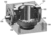
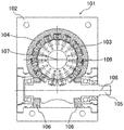
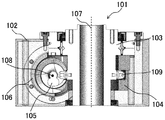
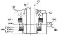
- FIG. 1 It is a perspective view which shows a part of the transmission mechanism as one Embodiment of this invention transparently. It is a perspective view which shows the partial cross section of the transmission mechanism of FIG. 1 transparently. It is a perspective view which shows the cross section seen from the upper surface of the transmission mechanism of FIG. It is sectional drawing seen from the side surface of the transmission mechanism of FIG. It is a perspective view of various shapes of the first filtration member in the transmission mechanism of this invention. It is sectional drawing seen from the upper surface of the transmission mechanism as another embodiment of this invention. It is sectional drawing seen from the side surface of the transmission mechanism of FIG. It is sectional drawing seen from the upper surface of the transmission mechanism as another embodiment of this invention. It is sectional drawing seen from the side surface of the transmission mechanism of FIG.
- FIG. 3 is a perspective view showing a partial cross section of the transmission mechanism of FIG. 13 transparently.
- FIG. 3 is a perspective view showing a partial cross section of the transmission mechanism of FIG. 13 transparently.
- FIG. 3 is a perspective view showing a partial cross section of the transmission mechanism of FIG. 13 transparently.
- FIG. 3 is a perspective view showing a partial cross section of the transmission mechanism of FIG. 13 transparently.
- FIG. 3 is a perspective view showing a partial cross section of the transmission mechanism of FIG. 13 transparently. It is a perspective view which shows the cross section seen from the upper surface of the transmission mechanism of FIG.
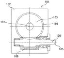
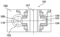
- the transmission mechanism 101 is housed in a housing 102, a first rotating member 103 housed in the housing 102 and rotatable about a first rotating member axis 107, and housed in the housing 102 to lubricate the first rotating member 103. It is provided with a lubricant for making it.
- the transmission mechanism 101 further includes a first filtration member 104 housed in the housing 102 for filtering dust contained in the lubricant.
- the first filtration member 104 is fixed to the housing 102.
- the lubricant is agitated by the rotation of the first rotating member 103 about the first rotating member axis 107, and the first filtering member 104 is in the direction in which the lubricant is flowed by the stirring from the first rotating member 103. It is provided in.
- the lubricant is agitated so as to be flowed radially outward by the centrifugal force from the first rotating member 103.
- a first filtration member 104 is provided on the radial outer side of the first rotating member 103, which is the direction in which the lubricant is flowed by stirring, and dust contained in the lubricant passing through the first filtration member 104 is first.
- the first filtration member 104 may be provided along the rotation direction of the first rotating member 103.
- the agitated lubricant is washed by the first filtration member 104 to maintain the cleanliness of the lubricant and suppress the deterioration of the lubricant. Further, by suppressing the deterioration of the lubricant, the deterioration of the accuracy of the transmission mechanism 101 is suppressed, the fretting and / or smearing under high speed and / or high load conditions is suppressed, and the maintenance cycle of the transmission mechanism 101 is extended. Therefore, the life of the transmission mechanism 101 can be extended.
- the first filtration member 104 can be installed in the conventional dead space of the transmission mechanism 101.
- the lubricant is convected by the heat generated in the first rotating member 103.
- Heat transfer forms include heat conduction, convection heat transfer, radiation, and the like.
- Convection means that buoyancy is generated and flow is generated because a density difference is formed by a temperature difference in a fluid.
- Convection heat transfer means that heat is carried by the convection of a fluid mass whose temperature has risen.
- the rotation by the first rotating member 103 generates heat in the first rotating member 103, and the heat generates convection of the lubricant.
- the first filtration member 104 may be provided in a direction in which the lubricant is flowed by convection from the first rotating member 103.
- the first filtration member 104 may be provided between the first rotating member 103 and the housing 102.
- the lubricant is flowed to the first filtration member 104 by this convection and passes through it, and the dust contained in the lubricant is adsorbed on the first filtration member 104.
- the first filtration member 104 may be provided along the rotation direction of the first rotating member 103.
- the convected lubricant is cleaned by the first filtration member 104 to maintain the cleanliness of the lubricant and suppress the deterioration of the lubricant.
- the life of the transmission mechanism 101 can be extended. Further, the heat generated in the high temperature first rotating member 103 is carried toward the low temperature housing 102 by convection heat transfer via the lubricant, and the lubricant is cooled in the vicinity of the housing 102.
- a gap is provided between the first filtration member 104 and the first rotating member 103, and the cooled lubricant is flowed from the housing 102 in the direction of the first rotating member 103 and enters the gap.
- the first rotating member 103 can be cooled, the temperature of the first rotating member 103 can be lowered, and the accuracy deterioration of the transmission mechanism 101 can be suppressed.
- the lubricant contained in the housing 102 may include at least one of a liquid lubricant, a semi-solid lubricant, a solid lubricant, a liquid crystal lubricant, and a gel-like lubricant.
- the lubricant may be grease, oil, or the like.
- the lubricant contained in the housing 101 can be selected as needed, but a lubricant capable of causing agitation and / or convection in the housing 102 is preferred.
- the heat generated in the transmission mechanism 101 causes heat conduction and convection in the housing 102 using the lubricant as a medium, and the generated heat is dissipated from the housing 102 to the atmosphere via the lubricant.
- the housing 102 as convection of the lubricant, in addition to natural convection heat transfer, forced convection heat transfer due to stirring caused by rotation of the first rotating member 103 around the first rotating member axis 107 occurs. .. In forced convection, the lower the viscosity of the medium, the higher the heat transfer coefficient.
- the lower the viscosity of a lubricant for example, a fluid lubricant or a liquid lubricant
- a lubricant for example, a fluid lubricant or a liquid lubricant
- the more the lubricant has a cooling effect due to forced convection It can be expected as a medium and is preferable as a medium.
- the thermal conductivity is lower than that of steel, non-ferrous metal, resin, and the like.
- the heat transfer coefficient is affected by the heat conductivity and surface area of the medium. Therefore, in order to increase the heat transfer coefficient, it is necessary to make the medium thinner, increase the surface area of the medium, and select a medium having good heat conductivity. is there.
- the first rotating member 103 it is preferable to cool the first rotating member 103 while efficiently lubricating the first rotating member 103 with a small amount of lubricant, but it is preferable that the first rotating member 103 is cooled with a small amount of lubricant.
- the degree of contamination of the lubricant tends to increase, and it is necessary to take measures against the contaminants, and it is also important to consider not to impair the cooling effect of forced convection by stirring.
- a minimum space for cooling the first rotating member 103 is secured in the housing 102, and high thermal conductivity (high thermal conductivity) that is expected to have a cooling action (
- a first filter member 104 having a material (steel, non-iron, resin, etc.), shape, etc.) may be adopted, and / or a first filter member 104 having a cleaning action against contaminants may be adopted.
- the lubricant accommodated in the housing 101 can be selected, the material, shape, etc. of the first filtration member 104 can be selected, and the optimum lubricant and the first filtration member 104 can be adopted. ..
- maintenance such as refueling and waste oil treatment is economical, and it is expected that the environmental load will be reduced.
- the first rotating member 103 may include a bearing 109 as a component for transmitting power.
- the lubricant is agitated by the rotation of the bearing 109 about the axis 107 of the first rotating member, and the first filtration member 104 is provided in the direction in which the lubricant is flowed by the agitation from the bearing 109.
- the bearing 109 rotates about the first rotating member axis 107
- the lubricant is agitated so as to flow outward in the radial direction by centrifugal force.
- a first filtration member 104 is provided on the radial outer side of the bearing 109 in which the lubricant is flowed by stirring, and dust contained in the lubricant passing through the first filtration member 104 is collected from the first filtration member 104. Is adsorbed on. Further, the rotation of the bearing 109 generates heat in the bearing 109, and the heat generates convection of the lubricant. For example, convection occurs in the direction away from the high temperature bearing 109. Therefore, even if the first filtration member 104 is provided in the direction in which the lubricant is flowed by the convection from the bearing 109, for example, on the upper side or the lower side of the bearing 109, or between the bearing 109 and the housing 102.
- the lubricant is flowed to the first filtration member 104 by this convection and passes through it, and the dust contained in the lubricant is adsorbed on the first filtration member 104.
- the first filtration member 104 may be provided along the rotation direction of the first rotating member 103 so as to surround the bearing 109.
- the first rotating member 103 may be provided with gears, for example, as long as it can transmit power. Similar to the bearing 109, the lubricant is agitated by the rotation around the first rotating member axis 107 of the tooth portion, and the first filtration member 104 is provided in the direction in which the lubricant is flowed by the agitation from the tooth portion. Be done. Further, the lubricant is convected by the heat generated in the tooth portion by the rotation by the tooth portion, and the first filtration member 104 is provided in the direction in which the lubricant is flowed by the convection from the first rotating member 103.
- the first filtration member 104 may adsorb dust having a small particle size according to the direction in which the lubricant is flowed from the first rotating member 103 by stirring and / or convection.
- the lubricant produces agitation and / or convection depending on the shape of the first rotating member 103.
- the first filtration member 104 adsorbs dust having a large particle size in a portion close to the portion of the first rotating member 103 that causes stirring and / or convection of the lubricant, and causes stirring and / or convection. It may be configured to gradually adsorb dust having a small particle size as the distance from the rotating member 103 of the above increases.
- first rotating member 103 when the first rotating member 103 includes the bearing 109 or the tooth portion, stirring and / or convection is generated by the bearing 109 or the tooth portion, so that the upper side, the lower side, and the bearing 109 of the bearing 109 or the tooth portion are generated.
- a first filtering member 104 is provided between the tooth portion and the housing 102, and the first filtering member 104 adsorbs dust having a large particle size in the bearing 109 or a portion close to the tooth portion to provide the bearing. It may be configured to gradually adsorb dust having a smaller particle size as the distance from the 109 or the tooth portion increases.
- the first filtration member 104 may be made of a porous material.
- the size of the pores of the porous material is made coarse in the portion close to the portion of the first rotating member 103 that causes the agitation and / or convection of the lubricant, so that the agitation and / or convection of the lubricant is generated.
- the first filtration member 104 may have a prefeltration function so that it becomes finer gradually as it moves away from the portion of the rotating member 103 of 1.
- the first filtration member 104 may be removable from the housing 102.
- the first filtration member 104 is clogged by adsorbing dust contained in the lubricant flowed by stirring and / or convection from the first rotating member 103, but the first filtration member 104 is housed 102.
- the first filtration member 104 can be removed from the housing 102 and the first filtration member 104 can be housed in the housing 102 again, or can be replaced with a new first filtration member 104 and housed in the housing 102. it can.
- the first filtration member 104 is arranged with the direction and / or amount of the lubricant flown by stirring and / or convection from the first rotating member 103, and the first filtration member 104. It may have various shapes depending on the size of the space, the properties of the material used for the first filtration member 104, the size and / or amount of dust contained in the lubricant, and the like.
- the first filtration member 104 may have a substantially U-shaped cross section as shown in (a), and has a cross section as shown in (b) according to the size and / or amount of dust adsorbed.
- the direction of the lubricant flowed by the stirring and / or convection from the first rotating member 103 of the first filtering member 104 is the axial direction with respect to the first rotating member axis 107, ( It may be an axial flow type as in d), and the direction of the lubricant flowed by stirring and / or convection from the first rotating member 103 is the radial direction with respect to the first rotating member axis 107. In some cases, it may be a depth pleated type (radial flow type) as in (e).
- the first filtration member 104 adsorbs dust having a large particle size in a portion close to the portion of the first rotating member 103 that causes agitation and / or convection of the lubricant, and agitation and / or convection of the lubricant.
- a multi-layer type may be used as in (f).
- the first filtration member 104 may be a member such as a sponge, felt, or the like, a member having magnetism, or a member having high adsorption to dust contained in the lubricant. Just do it.
- the transmission mechanism 101 further includes a second rotating member 105 that is lubricated by a lubricant and can rotate about the second rotating member axis 108. Due to the contact between the first rotating member 103 and the second rotating member 105, the rotation of one of the first rotating member 103 and the second rotating member 105 is caused by the first rotating member 103 and the second rotating member 105. Allows rotation of the other of the rotating members 105 of.
- the contact between the first rotating member 103 and the second rotating member 105 causes the first rotating member 103 as an output shaft to rotate, and also
- the second rotating member 105 as an output shaft is rotated by the contact between the first rotating member 103 and the second rotating member 105.
- the lubricant is agitated by the portion of the first rotating member 103 that is not in contact with the second rotating member 105, and the first rotating member 103 is rotated.
- the filtration member 104 is provided in a direction in which the lubricant is flowed by stirring from a portion of the first rotating member 103 that is not in contact with the second rotating member 105.
- the lubricant becomes the second rotating member 105 of the first rotating member 103. It is agitated so as to flow outward in the radial direction by the centrifugal force from the non-contact portion.
- the first filtration member 104 is provided on the radial outer side of the portion of the first rotation member 103 that is not in contact with the second rotation member 105, which is the direction in which the lubricant is flowed by stirring, and the first filtration member
- the dust contained in the lubricant passing through 104 is adsorbed on the first filtration member 104.
- the first filtration member 104 may be provided along a portion of the first rotating member 103 that is not in contact with the second rotating member 105.
- the agitated lubricant is washed by the first filtration member 104 to maintain the cleanliness of the lubricant and suppress the deterioration of the lubricant.
- the life of the transmission mechanism 101 can be extended.
- the transmission mechanism 101 may further include a second filtration member 106 housed in the housing 102 for filtering dust contained in the lubricant.
- the second filtration member 106 is fixed to the housing 102. While the first rotating member 103 and the second rotating member 105 are rotating, the lubricant is agitated by the portion of the second rotating member 105 that is not in contact with the first rotating member 103, and the second rotating member 105 is rotated.
- the filtration member 106 is provided in a direction in which the lubricant is flowed by stirring from a portion of the second rotating member 105 that is not in contact with the first rotating member 103.
- the second rotating member 105 when the second rotating member 105 is provided with a screw-shaped groove for contacting the first rotating member 103, the second rotating member 105 makes a second rotation while contacting the first rotating member 103.
- the lubricant flows along the second rotating member axis 108 due to the screw effect of the screw-shaped groove that is not in contact with the first rotating member 103 of the second rotating member 105. It is stirred so as to be.
- the second filtration member 106 is provided outside the axis direction of the second rotating member axis 108, which is the direction in which the lubricant is flowed by stirring, and the dust contained in the lubricant passing through the second filtration member 106 is the first.
- the second filtration member 106 may be provided at the end of the screw-shaped groove.
- the agitated lubricant is washed by the second filtration member 106 to maintain the cleanliness of the lubricant and suppress the deterioration of the lubricant. Further, by suppressing the deterioration of the lubricant, the deterioration of the accuracy of the transmission mechanism 101 is suppressed, the fretting and / or smearing under high speed and / or high load conditions is suppressed, and the maintenance cycle of the transmission mechanism 101 is extended. Therefore, the life of the transmission mechanism 101 can be extended.
- the lubricant is convected by the heat generated by the second rotating member 105.
- the rotation by the second rotating member 105 generates heat in the second rotating member 105, and the heat generates convection of the lubricant.
- the second filtration member 106 may be provided in a direction in which the lubricant is flowed by convection from the second rotating member. For example, convection is generated from the hot second rotating member 105 in the direction of the cold housing 102. Therefore, a second filtration member 106 may be provided between the second rotating member 105 and the housing 102.
- the lubricant is flowed through the second filtration member 106 by this convection and passes through it, and the dust contained in the lubricant is adsorbed on the second filtration member 106.
- the second filtration member 106 may be provided along the rotation direction of the second rotating member 105.
- the convected lubricant is cleaned by the second filtration member 106 to maintain the cleanliness of the lubricant and suppress the deterioration of the lubricant. Further, by suppressing the deterioration of the lubricant, the deterioration of the accuracy of the transmission mechanism 101 is suppressed, the fretting and / or smearing under high speed and / or high load conditions is suppressed, and the maintenance cycle of the transmission mechanism 101 is extended.
- the life of the transmission mechanism 101 can be extended. Further, the heat generated in the high temperature second rotating member 105 is carried toward the low temperature housing 102 by convection heat transfer via the lubricant, and the lubricant is cooled in the vicinity of the housing 102. A gap is provided between the second filtration member 106 and the second rotating member 105, and the cooled lubricant is flowed from the housing 102 in the direction of the second rotating member 105 and enters the gap. The second rotating member 105 can be cooled, the temperature of the second rotating member 105 can be lowered, and the accuracy deterioration of the transmission mechanism 101 can be suppressed.
- the first rotating member 103 includes a plurality of bearings 109 for contacting the second rotating member 105 along the rotation direction thereof, and the second rotating member 105 has a shape that engages with the plurality of bearings 109. You may have.
- a transmission mechanism 101 there is, for example, a drum-shaped cam mechanism. While the first rotating member 103 and the second rotating member 105 are rotating, the lubricant is agitated by the bearing 109 which is not in contact with the second rotating member 105, and the first filtering member 104 lubricates.
- the agent is provided in a direction in which the agent flows from the bearing 109 which is not in contact with the second rotating member 105.
- the first filtration member 104 may be provided in the direction in which the lubricant is flowed by convection from the bearing 109.
- the first filtration member 104 may be provided along the rotation direction of the first rotating member 103 so as to surround the bearing 109 that is not in contact with the second rotating member 105.
- the first filtration member 104 may be housed in the housing 102 before the bearing 109 is attached to the first rotating member 103.
- Each bearing 109 may include an inner ring portion and a substantially cylindrical outer ring portion that can rotate around the inner ring portion along the side surface of the inner ring portion, and a roller, a needle, or the like may be provided between the inner ring portion and the outer ring portion. It may be a rolling contact bearing provided with a rolling element, or a sliding contact bearing not including a rolling element. Further, each bearing 109 may be a cam follower provided with a fixing member for fixing each bearing 109 to the first rotating member 103 inside the inner ring portion, and the fixing member is the main body portion of the first rotating member 103.
- each bearing 109 is fixed to the first rotating member 103 so that the outer ring portion can rotate by being fitted to the portion of the first rotating member 103 excluding the plurality of bearings 109.
- each bearing 109 may be a roller follower without a fixing member, and a fixing member as a member separate from the bearing 109 penetrates the inside of the inner ring portion and fits into the main body portion of the first rotating member 103.
- the second rotating member 105 has a shape that engages with a cam follower and a roller follower.
- each bearing 109 may be a ball, and the ball is engaged with the main body portion of the first rotating member 103, and the second rotating member 105 has a shape of engaging with the ball.
- the second rotating member 105 may be a cam having a cam rib and engaging with the bearing 109.
- Either the first rotating member 103 or the second rotating member 105 may be an input shaft or an output shaft.
- the shape of the cam may be a shape having a screw-shaped cam rib.
- the first rotating member is centered on the first rotating member axis 107 orthogonal to the second rotating member axis 108.
- a plurality of bearings 109 come into contact with the cam ribs one after another so that the 103 can rotate as an output shaft.
- the lubricant is agitated by the bearing 109 which is not in contact with the cam rib, and the first filtering member 104 has the lubricant second. It is provided in the direction of flowing from the bearing 109 that is not in contact with the rotating member 105. Further, the rotation of the bearing 109 generates heat in the bearing 109, and the heat generates convection of the lubricant. Therefore, the first filtration member 104 may be provided in the direction in which the lubricant is flowed by convection from the bearing 109.
- the bearing 109 makes rolling contact with the cam rib, the torque input from the first rotating member 103 or the second rotating member 105 as the input shaft, the second rotating member 105 or the second rotating member 105 as the output shaft.
- the transmission efficiency to the first rotating member 103 can be improved, and the life of the transmission mechanism 101 can be extended.
- the first rotating member 103 has high rigidity against an external force in the rotational direction.
- the plurality of bearings 109 may be radially attached to the outer peripheral surface of the main body portion of the first rotating member 103 having a substantially cylindrical shape, or the main body of the first rotating member 103 having a substantially cylindrical shape. It may be attached to the end face of the portion in a circular shape.
- the first filtration member 104 may be provided on the lower side and the upper side in the axial direction of the first rotating member axis 107 with respect to the bearing 109.
- the lower and upper first filtration members 104 may be of the same type, or may be of the same type, depending on the size of the dust contained in the lubricant flushed by agitation and / or convection from the first rotating member 103. It may be of a different type.
- the second filtration member 106 may be provided outside the axis direction of the second rotating member axis 108. Good.
- the second rotating member 105 is provided with a screw-shaped groove
- the lubricant is applied to the first rotating member 105. Due to the screw effect of the screw-shaped groove that is not in contact with the rotating member 103, the mixture is stirred so as to flow along the second rotating member axis 108.
- a second filtration member 106 is provided at the end of the screw-shaped groove, and dust contained in the lubricant is adsorbed by the second filtration member 106.
- the second rotating member 105 may rotate about the second rotating member axis 108 in any direction, and the lubricant may flow along the second rotating member axis 108 in any direction.
- the second filtration member 106 may be provided at both ends of the screw groove.
- the second filtration member 106 in the transmission mechanism 101, may be provided along the rotation direction of the second rotating member axis 108.
- a second filtration member 106 is provided on the radial outer side of the second rotating member 105, which is the direction in which the lubricant is flowed by stirring, and the dust contained in the lubricant passing through the second filtration member 106 is second. Is adsorbed on the filtration member 106 of.
- the first filtration member 104 comprises the upper and lower sides of the bearing 109 and the bearing 109 and housing in the direction in which the lubricant is flowed by stirring and / or convection from the bearing 109. It may be provided along the rotation direction of the first rotating member 103 so as to surround the bearing 109 with the 102.
- the first filtration member 104 is provided on the lower side and the upper side in the axial direction of the first rotating member axis 107 with respect to the bearing 109, and is the lower side and the upper side.
- Both of the filtration members 104 of No. 1 have a first layer 104a that adsorbs dust having a large particle size in a portion close to the bearing 109, and a second layer 104b that adsorbs dust having an intermediate particle size in a portion intermediate from the bearing 109.
- a multi-layer type having a third layer 104c for adsorbing dust having a small particle size in a portion far from the bearing 109 may be used. Further, as shown in FIG.
- first filtration member 104 may be a multi-layer type.
- the first layer 104a, the second layer 104b, and the third layer 104c do not all have to be layers that adsorb dust.
- the first layer 104a adsorbs dust having a large particle size.
- the third layer 104c is a layer for heat transfer, and the like.
- the third layer 104c may be a layer having different properties, and the properties of the layers may be selected as needed.
- the first rotating member 103 has a gear having a plurality of tooth portions 110 for contacting the second rotating member 105 along the rotation direction thereof.
- the second rotating member 105 may have a shape that engages with the tooth portion 110.
- a transmission mechanism 101 there is, for example, a worm gear mechanism. While the first rotating member 103 and the second rotating member 105 are rotating, the lubricant is agitated by the tooth portions 110 that are not in contact with the second rotating member 105, and the first filtering member 104 receives the first filtering member 104. The lubricant is provided in the direction of flowing from the tooth portion 110 that is not in contact with the second rotating member 105.
- the first filtration member 104 may be provided in the direction in which the lubricant is flowed by convection from the tooth portion 110.
- the second filtration member 106 may be provided outside the axis direction of the second rotating member axis 108, in the direction of rotation of the second rotating member axis 108. It may be provided along the line.
- the lubricant is agitated by the portion of the second rotating member 105 that is not in contact with the rotating member 103, and the second filtering member 106 Is provided in the direction in which the lubricant is flowed from the portion of the second rotating member 105 that is not in contact with the first rotating member 105.
- the rotation by the second rotating member 105 generates heat in the second rotating member 105, and the heat generates convection of the lubricant. Therefore, the second filtration member 106 may be provided in the direction in which the lubricant is flowed by convection from the second rotating member 105. As shown in FIG.
- the first filtering member 104 includes the upper and lower sides of the tooth 110, and the tooth 110 and the housing in the direction in which the lubricant is flowed by stirring and / or convection from the tooth 110. It may be provided along the rotation direction of the first rotating member 103 so as to surround the tooth portion 110 which is not in contact with the second rotating member 105 with the 102.
- the first filtering member 104 and / or the second filtering member 106 may be any as long as it can adsorb dust contained in the lubricant flowed by stirring and / or convection, and the first filtering member 104 and / or the second filtering member 106 is housed in the housing 102.
- the transmission mechanism 101 including the filtering member 104 and / or the second filtering member 106 is a drum-shaped cam (roller gear cam, concave global cam), a cylindrical cam (cylindrical cam, barrel cam) as the second rotating member 105.
- a cam mechanism including a cam having various screw-shaped cam ribs such as a drum-shaped cam (convex global cam) may be used.
- the transmission mechanism 101 may be a ball reducer, a worm reducer, a planetary gear reducer, a wave gear reducer, a traction drive reducer, or the like.
- the transmission mechanism 101 makes contact between the first rotating member 103 and the second rotating member 105 within the width of the line connecting the first rotating member axis 107 and the second rotating member axis 108.
- It may be an circumscribed type having a positional relationship with each other, and the first rotating member 103 and the second rotating member 103 and the second rotating member are outside the width of the line connecting the first rotating member axis 107 and the second rotating member axis 108.
- It may be an inscribed type that has a positional relationship in which contact with the member 105 is performed.
- the inscribed type includes an inscribed parallel cam mechanism, an inscribed trochoidal gear mechanism, and the like.
- Transmission mechanism 102 Housing 103 First rotating member 104 First filtering member 104a First layer 104b Second layer 104c Third layer 105 Second rotating member 106 Second filtering member 107 First rotating member Axis 108 Second rotating member Axis 109 Bearing 110 Tooth
Landscapes
- Engineering & Computer Science (AREA)
- General Engineering & Computer Science (AREA)
- Mechanical Engineering (AREA)
- General Details Of Gearings (AREA)
Priority Applications (5)
| Application Number | Priority Date | Filing Date | Title |
|---|---|---|---|
| EP20897323.0A EP4071398A4 (en) | 2019-12-06 | 2020-11-24 | Transmission mechanism |
| CN202080079325.7A CN114667405A (zh) | 2019-12-06 | 2020-11-24 | 传递机构 |
| KR1020227018739A KR20220105648A (ko) | 2019-12-06 | 2020-11-24 | 전달 기구 |
| US17/782,523 US20230009870A1 (en) | 2019-12-06 | 2020-11-24 | Transmission mechanism |
| JP2021562582A JP7510437B2 (ja) | 2019-12-06 | 2020-11-24 | 伝達機構 |
Applications Claiming Priority (2)
| Application Number | Priority Date | Filing Date | Title |
|---|---|---|---|
| JP2019-221102 | 2019-12-06 | ||
| JP2019221102 | 2019-12-06 |
Publications (1)
| Publication Number | Publication Date |
|---|---|
| WO2021111923A1 true WO2021111923A1 (ja) | 2021-06-10 |
Family
ID=76222136
Family Applications (1)
| Application Number | Title | Priority Date | Filing Date |
|---|---|---|---|
| PCT/JP2020/043604 Ceased WO2021111923A1 (ja) | 2019-12-06 | 2020-11-24 | 伝達機構 |
Country Status (7)
| Country | Link |
|---|---|
| US (1) | US20230009870A1 (https=) |
| EP (1) | EP4071398A4 (https=) |
| JP (1) | JP7510437B2 (https=) |
| KR (1) | KR20220105648A (https=) |
| CN (1) | CN114667405A (https=) |
| TW (1) | TWI878362B (https=) |
| WO (1) | WO2021111923A1 (https=) |
Families Citing this family (1)
| Publication number | Priority date | Publication date | Assignee | Title |
|---|---|---|---|---|
| CN117432751B (zh) * | 2023-12-22 | 2024-08-30 | 江苏微特利电机股份有限公司 | 新能源驱动用永磁同步电机传动机构 |
Citations (6)
| Publication number | Priority date | Publication date | Assignee | Title |
|---|---|---|---|---|
| JPS59141294U (ja) * | 1982-06-30 | 1984-09-20 | いすゞ自動車株式会社 | 油溜室内部の異物除去装置 |
| JPS62153460U (https=) * | 1986-03-20 | 1987-09-29 | ||
| JPS6314063U (https=) * | 1986-07-14 | 1988-01-29 | ||
| JPS6364962U (https=) * | 1986-10-20 | 1988-04-28 | ||
| JP2017089663A (ja) * | 2015-11-02 | 2017-05-25 | 株式会社三共製作所 | ローラギヤカム機構 |
| JP2019007565A (ja) * | 2017-06-26 | 2019-01-17 | いすゞ自動車株式会社 | 変速機の潤滑油浄化装置 |
Family Cites Families (7)
| Publication number | Priority date | Publication date | Assignee | Title |
|---|---|---|---|---|
| BE756515A (fr) * | 1970-01-21 | 1971-03-01 | Gen Electric | Boite de transmission a engrenages avec un dispositif pour empecher l'elevation de la temperature et procede pour empecher cetteaugmentation |
| US5599247A (en) * | 1994-06-15 | 1997-02-04 | Kanzaki Kokyukoki Mfg. Co., Ltd. | Transmission assembly for tractors |
| SE507536C2 (sv) * | 1996-10-25 | 1998-06-15 | Volvo Ab | Oljerenare i en transmission |
| JP2001263460A (ja) * | 2000-03-17 | 2001-09-26 | Hitachi Constr Mach Co Ltd | 減速装置 |
| JP2013002572A (ja) * | 2011-06-17 | 2013-01-07 | Ricoh Co Ltd | 駆動装置及びこれを備えた画像形成装置 |
| JP2014101989A (ja) | 2012-11-22 | 2014-06-05 | Toyota Motor Corp | 回転駆動装置 |
| JP2018103676A (ja) * | 2016-12-22 | 2018-07-05 | 本田技研工業株式会社 | 動力装置 |
-
2020
- 2020-10-08 TW TW109135012A patent/TWI878362B/zh active
- 2020-11-24 EP EP20897323.0A patent/EP4071398A4/en not_active Withdrawn
- 2020-11-24 CN CN202080079325.7A patent/CN114667405A/zh not_active Withdrawn
- 2020-11-24 JP JP2021562582A patent/JP7510437B2/ja active Active
- 2020-11-24 US US17/782,523 patent/US20230009870A1/en not_active Abandoned
- 2020-11-24 WO PCT/JP2020/043604 patent/WO2021111923A1/ja not_active Ceased
- 2020-11-24 KR KR1020227018739A patent/KR20220105648A/ko active Pending
Patent Citations (6)
| Publication number | Priority date | Publication date | Assignee | Title |
|---|---|---|---|---|
| JPS59141294U (ja) * | 1982-06-30 | 1984-09-20 | いすゞ自動車株式会社 | 油溜室内部の異物除去装置 |
| JPS62153460U (https=) * | 1986-03-20 | 1987-09-29 | ||
| JPS6314063U (https=) * | 1986-07-14 | 1988-01-29 | ||
| JPS6364962U (https=) * | 1986-10-20 | 1988-04-28 | ||
| JP2017089663A (ja) * | 2015-11-02 | 2017-05-25 | 株式会社三共製作所 | ローラギヤカム機構 |
| JP2019007565A (ja) * | 2017-06-26 | 2019-01-17 | いすゞ自動車株式会社 | 変速機の潤滑油浄化装置 |
Non-Patent Citations (1)
| Title |
|---|
| See also references of EP4071398A4 * |
Also Published As
| Publication number | Publication date |
|---|---|
| JPWO2021111923A1 (https=) | 2021-06-10 |
| US20230009870A1 (en) | 2023-01-12 |
| EP4071398A4 (en) | 2024-01-10 |
| TW202129190A (zh) | 2021-08-01 |
| EP4071398A1 (en) | 2022-10-12 |
| JP7510437B2 (ja) | 2024-07-03 |
| TWI878362B (zh) | 2025-04-01 |
| KR20220105648A (ko) | 2022-07-27 |
| CN114667405A (zh) | 2022-06-24 |
Similar Documents
| Publication | Publication Date | Title |
|---|---|---|
| JP5839496B2 (ja) | 遊星歯車装置 | |
| US20160076631A1 (en) | Electric Linear Actuator | |
| JP6479259B2 (ja) | 遊星歯車装置および車輪駆動装置 | |
| EP0928909A1 (en) | Transmission for automobiles and bearing therefor | |
| JP2012072815A (ja) | 玉軸受用保持器及び玉軸受 | |
| WO2018047820A1 (ja) | シール付軸受 | |
| JP2007107588A (ja) | 転がり軸受 | |
| WO2021111923A1 (ja) | 伝達機構 | |
| JP6122786B2 (ja) | ディファレンシャル装置の潤滑構造 | |
| JP5598061B2 (ja) | 円すいころ軸受装置 | |
| JP2002286044A (ja) | トランスミッション用密封板付転がり軸受及びトランスミッション | |
| CN218670429U (zh) | Rv减速器、工业机器人 | |
| WO2021111922A1 (ja) | 伝達機構 | |
| JP2006234100A (ja) | 複列アンギュラ玉軸受および車両用ピニオン軸支持装置 | |
| TWI791090B (zh) | 凸輪機構 | |
| JP2012251652A (ja) | 等速自在継手 | |
| JP7754061B2 (ja) | オイルシール構造およびその製造方法 | |
| JP4547601B2 (ja) | 減速機とそれを用いた電動パワーステアリング装置 | |
| JP7219050B2 (ja) | トランスアクスル | |
| WO2022202545A1 (ja) | シール付軸受 | |
| JPH066205Y2 (ja) | ガスタ−ビンエンジンの熱交換器駆動軸用軸受構造 | |
| JP2005127481A (ja) | 減速機とそれを用いた電動パワーステアリング装置 | |
| KR20180000549U (ko) | 기어샤프트와 동력전달기어의 결합구조 | |
| JP2024076053A (ja) | 保持器、その保持器を用いた保持器付き針状ころ及び軸受装置 | |
| JP6740936B2 (ja) | 軸受潤滑構造 |
Legal Events
| Date | Code | Title | Description |
|---|---|---|---|
| 121 | Ep: the epo has been informed by wipo that ep was designated in this application |
Ref document number: 20897323 Country of ref document: EP Kind code of ref document: A1 |
|
| ENP | Entry into the national phase |
Ref document number: 2021562582 Country of ref document: JP Kind code of ref document: A |
|
| ENP | Entry into the national phase |
Ref document number: 20227018739 Country of ref document: KR Kind code of ref document: A |
|
| NENP | Non-entry into the national phase |
Ref country code: DE |
|
| ENP | Entry into the national phase |
Ref document number: 2020897323 Country of ref document: EP Effective date: 20220706 |
|
| WWW | Wipo information: withdrawn in national office |
Ref document number: 1020227018739 Country of ref document: KR |