WO2021111798A1 - 缶容器 - Google Patents
缶容器 Download PDFInfo
- Publication number
- WO2021111798A1 WO2021111798A1 PCT/JP2020/041419 JP2020041419W WO2021111798A1 WO 2021111798 A1 WO2021111798 A1 WO 2021111798A1 JP 2020041419 W JP2020041419 W JP 2020041419W WO 2021111798 A1 WO2021111798 A1 WO 2021111798A1
- Authority
- WO
- WIPO (PCT)
- Prior art keywords
- container
- dome
- inner peripheral
- peripheral surface
- axis
- Prior art date
Links
- 230000002093 peripheral effect Effects 0.000 claims abstract description 41
- 238000000465 moulding Methods 0.000 claims description 11
- 230000006835 compression Effects 0.000 claims description 6
- 238000007906 compression Methods 0.000 claims description 6
- 238000005452 bending Methods 0.000 claims description 2
- 238000007796 conventional method Methods 0.000 description 4
- 238000007634 remodeling Methods 0.000 description 4
- 238000005259 measurement Methods 0.000 description 2
- XLYOFNOQVPJJNP-UHFFFAOYSA-N water Substances O XLYOFNOQVPJJNP-UHFFFAOYSA-N 0.000 description 2
- 229910000838 Al alloy Inorganic materials 0.000 description 1
- 235000013361 beverage Nutrition 0.000 description 1
- 235000014171 carbonated beverage Nutrition 0.000 description 1
- 230000006378 damage Effects 0.000 description 1
- 238000013461 design Methods 0.000 description 1
- 230000006866 deterioration Effects 0.000 description 1
- 238000010586 diagram Methods 0.000 description 1
- 235000013305 food Nutrition 0.000 description 1
- 230000002452 interceptive effect Effects 0.000 description 1
- 239000007788 liquid Substances 0.000 description 1
- 239000000463 material Substances 0.000 description 1
- 238000000034 method Methods 0.000 description 1
- TWNQGVIAIRXVLR-UHFFFAOYSA-N oxo(oxoalumanyloxy)alumane Chemical compound O=[Al]O[Al]=O TWNQGVIAIRXVLR-UHFFFAOYSA-N 0.000 description 1
- 239000002994 raw material Substances 0.000 description 1
- 230000001954 sterilising effect Effects 0.000 description 1
- 238000004659 sterilization and disinfection Methods 0.000 description 1
Images


Classifications
-
- B—PERFORMING OPERATIONS; TRANSPORTING
- B65—CONVEYING; PACKING; STORING; HANDLING THIN OR FILAMENTARY MATERIAL
- B65D—CONTAINERS FOR STORAGE OR TRANSPORT OF ARTICLES OR MATERIALS, e.g. BAGS, BARRELS, BOTTLES, BOXES, CANS, CARTONS, CRATES, DRUMS, JARS, TANKS, HOPPERS, FORWARDING CONTAINERS; ACCESSORIES, CLOSURES, OR FITTINGS THEREFOR; PACKAGING ELEMENTS; PACKAGES
- B65D1/00—Containers having bodies formed in one piece, e.g. by casting metallic material, by moulding plastics, by blowing vitreous material, by throwing ceramic material, by moulding pulped fibrous material, by deep-drawing operations performed on sheet material
- B65D1/12—Cans, casks, barrels, or drums
- B65D1/14—Cans, casks, barrels, or drums characterised by shape
- B65D1/16—Cans, casks, barrels, or drums characterised by shape of curved cross-section, e.g. cylindrical
- B65D1/165—Cylindrical cans
-
- B—PERFORMING OPERATIONS; TRANSPORTING
- B65—CONVEYING; PACKING; STORING; HANDLING THIN OR FILAMENTARY MATERIAL
- B65D—CONTAINERS FOR STORAGE OR TRANSPORT OF ARTICLES OR MATERIALS, e.g. BAGS, BARRELS, BOTTLES, BOXES, CANS, CARTONS, CRATES, DRUMS, JARS, TANKS, HOPPERS, FORWARDING CONTAINERS; ACCESSORIES, CLOSURES, OR FITTINGS THEREFOR; PACKAGING ELEMENTS; PACKAGES
- B65D1/00—Containers having bodies formed in one piece, e.g. by casting metallic material, by moulding plastics, by blowing vitreous material, by throwing ceramic material, by moulding pulped fibrous material, by deep-drawing operations performed on sheet material
- B65D1/12—Cans, casks, barrels, or drums
- B65D1/14—Cans, casks, barrels, or drums characterised by shape
- B65D1/16—Cans, casks, barrels, or drums characterised by shape of curved cross-section, e.g. cylindrical
-
- B—PERFORMING OPERATIONS; TRANSPORTING
- B21—MECHANICAL METAL-WORKING WITHOUT ESSENTIALLY REMOVING MATERIAL; PUNCHING METAL
- B21D—WORKING OR PROCESSING OF SHEET METAL OR METAL TUBES, RODS OR PROFILES WITHOUT ESSENTIALLY REMOVING MATERIAL; PUNCHING METAL
- B21D51/00—Making hollow objects
- B21D51/16—Making hollow objects characterised by the use of the objects
- B21D51/26—Making hollow objects characterised by the use of the objects cans or tins; Closing same in a permanent manner
-
- B—PERFORMING OPERATIONS; TRANSPORTING
- B65—CONVEYING; PACKING; STORING; HANDLING THIN OR FILAMENTARY MATERIAL
- B65D—CONTAINERS FOR STORAGE OR TRANSPORT OF ARTICLES OR MATERIALS, e.g. BAGS, BARRELS, BOTTLES, BOXES, CANS, CARTONS, CRATES, DRUMS, JARS, TANKS, HOPPERS, FORWARDING CONTAINERS; ACCESSORIES, CLOSURES, OR FITTINGS THEREFOR; PACKAGING ELEMENTS; PACKAGES
- B65D1/00—Containers having bodies formed in one piece, e.g. by casting metallic material, by moulding plastics, by blowing vitreous material, by throwing ceramic material, by moulding pulped fibrous material, by deep-drawing operations performed on sheet material
- B65D1/40—Details of walls
- B65D1/42—Reinforcing or strengthening parts or members
- B65D1/46—Local reinforcements, e.g. adjacent closures
Definitions
- the present invention relates to a can container.
- Two-piece cans and bottle cans are known as can containers in which the contents of beverages and foods are filled and sealed. These cans have at least a can body and a can bottom.
- the shape of the can bottom for increasing the pressure resistance is to form a dome portion in which the central portion of the can bottom is recessed in a dome shape toward the inside of the can container along the can axis direction, and the outside of the dome portion.
- An annular convex portion serving as a support portion is formed on the peripheral edge.
- the shapes of the dome portion and the annular convex portion described above are appropriately designed.
- the inner peripheral wall connected to the dome portion is formed.
- a first concave curved surface portion having a curved shape that is concave toward the outside in the radial direction orthogonal to the can axis is formed, and the dome portion includes a dome top located on the can axis.
- a second concave curved surface portion connected to the radially outer side of the dome top and forming a concave curved surface having a smaller radius of curvature than the dome top is formed, and the first concave curved surface portion and the second concave curved surface portion described above are formed on the outer peripheral edge portion of the dome portion. It has been proposed that a concave curved surface portion is connected to form a linear tapered portion in contact with the first curved surface portion and the second curved surface portion (see Patent Document 1 below).
- the dome portion and the annular convex portion are formed on the bottom portion, and then the inner peripheral wall of the annular convex portion is reform-molded to form the first concave curved surface portion and the tapered portion.
- the first concave curved surface portion is rolled to form a curved surface on the forming surface of the forming tool.
- the curved surface of the first concave curved surface portion has to have a radius of curvature that is large to some extent that roll molding is possible, and the inner peripheral surface of the annular convex portion is in the radial direction orthogonal to the can axis. There is a limit to making the amount of dents that are dented outwards deeper.
- the present invention has been proposed to deal with such a situation. That is, by further improving the shape of the bottom of the can container, it is an object to provide a can container capable of obtaining higher pressure resistance and maintaining the aesthetic appearance of the product.
- the can container according to the present invention has the following configuration. It is a can container and includes a can body and a can bottom.
- the can bottom is provided with a dome portion that is recessed toward the inside of the can container along the direction of the can shaft in the center, and is provided outside the dome portion.
- An annular convex portion that protrudes toward the outside of the can container is provided so as to form an annular support portion around the can container, and the inner peripheral surface from the support portion to the outer peripheral edge portion of the dome portion is the dome portion.
- a can container characterized in that the outer peripheral edge portion has a recess portion located in a direction away from the can axis from the innermost side of the inner peripheral surface.
- a vertical sectional view of a main part of a can container according to an embodiment of the present invention (longitudinal sectional view on the can axis). Enlarged vertical cross-sectional view of the annular convex portion (longitudinal view on the can axis).
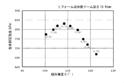
- Graph of can bottom pressure resistance measurement value (dome depth 13.45 mm before remodeling) when the inclination angle ⁇ is changed.
- Graph of can bottom pressure resistance measurement value (dome depth before remodeling 13.95 mm) when the inclination angle ⁇ is changed.
- FIGS. 1 and 2 show the cross-sectional shape by a diagram in which the description of the plate thickness is omitted.
- the can container 1 has a can body 1A and a can bottom 1B, and the can body 1A and the can bottom 1B cover the entire circumference around the can shaft O.
- the can bottom 1B includes a dome portion 10 and an annular convex portion 20, and in the illustrated example, the outer wall portion 30 is provided on the outside of the annular convex portion 20.
- the dome portion 10 is provided in the center of the can bottom 1B, and has a curved surface having a dome shape that is recessed toward the inside of the can container 1 along the direction of the can shaft O.
- the curved surface of the dome portion 10 shows an example having a first curved surface 11 having a radius of curvature R1 in the central portion and a second curved surface 12 having a radius of curvature R2 smaller than the radius R1 around the first curved surface 11. .
- the dome portion 10 may be a curved surface having a single radius of curvature.
- the annular convex portion 20 is formed so as to project outward along the can axis direction of the can container 1 so as to form an annular support portion 21 around the outer periphery of the dome portion 10.
- the support portion 21 is a portion that supports the can container 1 on a plane, and is formed on a support surface 21A orthogonal to the can axis O.
- the inner peripheral surface 22 from the support portion 21 of the annular convex portion 20 to the outer peripheral edge portion 10A of the dome portion 10 is inclined in the direction in which the inner peripheral surface 22 is separated from the can shaft O and is outside the dome portion 10. It has a recess portion 22A connected to the peripheral edge portion 10A.
- the outer peripheral edge portion 10A of the dome portion 10 is the innermost 22B of the inner peripheral surface 22 (the most can shaft O of the inner peripheral surface 22). It is located in the direction away from the can shaft O.
- the virtual line L1 which is in contact with the innermost 22B of the inner peripheral surface 22 and is parallel to the can axis O intersects the curved surface of the dome portion 10 (for example, the second curved surface 12).
- the recess portion 22A on the inner peripheral surface 22 has a linear tapered surface 22T in a vertical cross-sectional view on the can shaft O.
- the tapered surface 22T forms an obtuse angle of inclination ⁇ with the support surface 21A in contact with the support portion 21 described above.
- This inclination angle ⁇ is an angle on the can axis O side between the tapered surface 22T and the support surface 21A, and the angle is set to 100 ° to 125 ° in order to obtain high withstand strength at the can bottom 1B. Is preferable.
- the recess portion 22A on the inner peripheral surface 22 reaches the outer peripheral edge portion 10A of the dome portion 10 through the recess of the outermost 22C (the portion of the inner peripheral surface 22 farthest from the can shaft O) from the tapered surface 22T described above.
- the outermost 22C is not formed by roll molding as in the above-mentioned conventional technique, but is formed as a bent portion due to compression deformation in the can axis direction, so that the radius of curvature of the curved surface of the outermost 22C is conventional. It is set smaller (for example, 0.7 mm or less) than the radius of curvature of the first concave curved surface portion in the technique.
- the outermost 22C on the inner peripheral surface 22 can be recessed deeper in the direction away from the can shaft O with respect to the innermost 22B on the inner peripheral surface 22.
- the distance d (depth of the recess portion 22A) between the virtual line L1 and the virtual line L2 described above is a high withstand voltage of the can bottom 1B.
- the outermost 22C of the inner peripheral surface 22 is a compression deformation bent portion
- the inner peripheral surface 22 having the outermost 22C formed as the compression deformation bending portion can avoid the deterioration of the aesthetic appearance due to the roll forming marks (blackening due to the destruction of the aluminum oxide film).
- the outermost 22C is a compression deformation bent portion
- the height h from the support surface 21A to the outermost 22C is the molding height. This height h is preferably 2.0 mm to 4.0 mm in order to obtain a high pressure resistance of the can bottom 1B.
- the embodiment of the present invention having such a can bottom shape has a high can bottom pressure resistance strength as compared with the above-mentioned conventional technique.
- the pressure resistance strength of the can bottom here refers to the buckling strength until the concave shape of the can bottom is completely reversed.
- the recess portion 22A described above is formed by molding the dome portion 10 and the annular convex portion 20 on the can bottom 1B, and then performing reform molding to cause compression deformation.
- 4 and 5 show the above-mentioned inclination angle ⁇ using two types of bottom-shaped cans (capacity: 350 ml, ground contact diameter ⁇ 49) having a dome depth of 13.45 mm and 13.95 mm before remodeling. The difference in the withstand voltage strength of the can bottom is shown when the remodeling is performed by changing the above.
- the values in parentheses in the figure indicate the value of the height h (molding height from the support surface 21A to the outermost 22C) shown in FIG. 2 when the inclination angle ⁇ is changed.
- the desired can bottom pressure resistance strength can be obtained.
- the dome depth hs is increased, it is inevitably difficult to secure the internal volume of the can required to fill the contents from a certain range. ..
- the larger the inclination angle ⁇ is in a certain range the higher the can bottom pressure resistance strength is.
- the deformation mode is changed and only the dome portion 10 is inverted, and conversely, the can bottom pressure resistance strength is increased. It will decrease.
- a hydraulic buckling tester is used to seal the inside of the can container near the center of the can body in the can axis direction in an inverted state where the can bottom is not fixed, and water is discharged.
- the pressure inside the can container was raised at a pressurizing speed of 30 kPa / s by water pressure, and the pressure was measured as the lowest internal pressure at which the concave shape of the bottom of the can was reversed.
- the required value of the can bottom pressure resistance varies depending on the type of container, the liquid type of the contents, the sterilization conditions, etc. For example, when filling some carbonated drinks, high pressure resistance is required. Even in that case, it is judged that it is sufficient to have a withstand voltage of 690 kPa.
Landscapes
- Engineering & Computer Science (AREA)
- Mechanical Engineering (AREA)
- Ceramic Engineering (AREA)
- Containers Having Bodies Formed In One Piece (AREA)
- Rigid Containers With Two Or More Constituent Elements (AREA)
Priority Applications (4)
| Application Number | Priority Date | Filing Date | Title |
|---|---|---|---|
| US17/781,103 US20230002101A1 (en) | 2019-12-03 | 2020-11-05 | Can container |
| JP2021562516A JPWO2021111798A1 (zh) | 2019-12-03 | 2020-11-05 | |
| EP20895157.4A EP4071066A4 (en) | 2019-12-03 | 2020-11-05 | CAN CONTAINERS |
| CN202080073788.2A CN114616185B (zh) | 2019-12-03 | 2020-11-05 | 罐容器 |
Applications Claiming Priority (2)
| Application Number | Priority Date | Filing Date | Title |
|---|---|---|---|
| JP2019-218962 | 2019-12-03 | ||
| JP2019218962 | 2019-12-03 |
Publications (1)
| Publication Number | Publication Date |
|---|---|
| WO2021111798A1 true WO2021111798A1 (ja) | 2021-06-10 |
Family
ID=76222350
Family Applications (1)
| Application Number | Title | Priority Date | Filing Date |
|---|---|---|---|
| PCT/JP2020/041419 WO2021111798A1 (ja) | 2019-12-03 | 2020-11-05 | 缶容器 |
Country Status (5)
| Country | Link |
|---|---|
| US (1) | US20230002101A1 (zh) |
| EP (1) | EP4071066A4 (zh) |
| JP (1) | JPWO2021111798A1 (zh) |
| TW (1) | TWI757989B (zh) |
| WO (1) | WO2021111798A1 (zh) |
Citations (3)
| Publication number | Priority date | Publication date | Assignee | Title |
|---|---|---|---|---|
| JPH04123825A (ja) * | 1990-09-11 | 1992-04-23 | Kobe Steel Ltd | 耐圧強度が高いdi缶体の製造方法及び缶体 |
| JPH09285832A (ja) * | 1996-04-23 | 1997-11-04 | Kishimoto Akira | シームレス缶及びその成形法 |
| JP2016043991A (ja) | 2014-08-20 | 2016-04-04 | ユニバーサル製缶株式会社 | 缶 |
Family Cites Families (20)
| Publication number | Priority date | Publication date | Assignee | Title |
|---|---|---|---|---|
| US3416703A (en) * | 1966-02-24 | 1968-12-17 | Continental Can Co | Reinforced container |
| US3693828A (en) * | 1970-07-22 | 1972-09-26 | Crown Cork & Seal Co | Seamless steel containers |
| JPS5325186A (en) * | 1976-08-20 | 1978-03-08 | Daiwa Can Co Ltd | Metallic can for drink containing carbon dioxide or the like |
| US4266685A (en) * | 1979-11-30 | 1981-05-12 | Reynolds Metals Company | Can body and method for making same |
| US4834256A (en) * | 1987-07-31 | 1989-05-30 | Pac International, Inc. | Can with domed bottom structure |
| DE3930937A1 (de) * | 1989-09-15 | 1991-03-28 | Schmalbach Lubeca | Zweiteilige getraenkedose aus metall |
| JPH05338640A (ja) * | 1990-09-17 | 1993-12-21 | Aluminum Co Of America <Alcoa> | 絞り加工された容器の基部輪郭形状およびその製造方法 |
| US5261558A (en) * | 1990-12-21 | 1993-11-16 | Carnaudmetalbox Plc | Can bodies |
| US5718352A (en) * | 1994-11-22 | 1998-02-17 | Aluminum Company Of America | Threaded aluminum cans and methods of manufacture |
| US5421480A (en) * | 1993-04-08 | 1995-06-06 | Reynolds Metals Company | Thin-walled can having a displaceable bottom |
| US5394727A (en) * | 1993-08-18 | 1995-03-07 | Aluminum Company Of America | Method of forming a metal container body |
| GB9510515D0 (en) * | 1995-05-24 | 1995-07-19 | Metal Box Plc | Containers |
| US6132155A (en) * | 1995-10-23 | 2000-10-17 | Metal Container Corporation | Process for can bottom manufacture for improved strength and material use reduction |
| AU4329199A (en) * | 1998-06-03 | 1999-12-20 | Crown Cork & Seal Technologies Corporation | Can bottom having improved strength and apparatus for making same |
| US5971259A (en) * | 1998-06-26 | 1999-10-26 | Sonoco Development, Inc. | Reduced diameter double seam for a composite container |
| US6296139B1 (en) * | 1999-11-22 | 2001-10-02 | Mitsubishi Materials Corporation | Can manufacturing apparatus, can manufacturing method, and can |
| CA2483666C (en) * | 2002-04-30 | 2009-03-17 | Daiwa Can Company | Opening curled portion of metal can and forming method thereof |
| US7832589B2 (en) * | 2003-12-17 | 2010-11-16 | Crown Packaging Technology, Inc. | Reclosable metal container |
| US20230227237A1 (en) * | 2018-12-30 | 2023-07-20 | Caniel Industries A. T. G. Ltd. | Can and an urging member therefor |
| WO2021230210A1 (ja) * | 2020-05-12 | 2021-11-18 | 東洋製罐グループホールディングス株式会社 | 絞りしごき缶及び絞りしごき缶用塗装金属板 |
-
2020
- 2020-11-05 WO PCT/JP2020/041419 patent/WO2021111798A1/ja unknown
- 2020-11-05 EP EP20895157.4A patent/EP4071066A4/en active Pending
- 2020-11-05 JP JP2021562516A patent/JPWO2021111798A1/ja active Pending
- 2020-11-05 US US17/781,103 patent/US20230002101A1/en active Pending
- 2020-11-26 TW TW109141620A patent/TWI757989B/zh active
Patent Citations (3)
| Publication number | Priority date | Publication date | Assignee | Title |
|---|---|---|---|---|
| JPH04123825A (ja) * | 1990-09-11 | 1992-04-23 | Kobe Steel Ltd | 耐圧強度が高いdi缶体の製造方法及び缶体 |
| JPH09285832A (ja) * | 1996-04-23 | 1997-11-04 | Kishimoto Akira | シームレス缶及びその成形法 |
| JP2016043991A (ja) | 2014-08-20 | 2016-04-04 | ユニバーサル製缶株式会社 | 缶 |
Non-Patent Citations (1)
| Title |
|---|
| See also references of EP4071066A4 |
Also Published As
| Publication number | Publication date |
|---|---|
| CN114616185A (zh) | 2022-06-10 |
| JPWO2021111798A1 (zh) | 2021-06-10 |
| TW202133964A (zh) | 2021-09-16 |
| EP4071066A4 (en) | 2024-01-24 |
| US20230002101A1 (en) | 2023-01-05 |
| EP4071066A1 (en) | 2022-10-12 |
| TWI757989B (zh) | 2022-03-11 |
Similar Documents
| Publication | Publication Date | Title |
|---|---|---|
| US3905507A (en) | Profiled bottom wall for containers | |
| US8505765B2 (en) | Container end closure with improved chuck wall provided between a peripheral cover hook and countersink | |
| US4953738A (en) | One piece can body with domed bottom | |
| US20010009107A1 (en) | Can bottom having improved strength and apparatus for making same | |
| HU213239B (en) | Holder made of metal plate | |
| WO2011027910A1 (ja) | 有底筒状体形状の缶容器本体およびそれに飲料を充填した飲料缶製品 | |
| JP5085411B2 (ja) | レトルト対応小容量ネジ付き缶 | |
| WO2021111798A1 (ja) | 缶容器 | |
| JP2024045461A (ja) | 缶体 | |
| JPH04311445A (ja) | 缶本体 | |
| US5626228A (en) | Thin-walled can having plurality of supporting feet with two support features | |
| WO2021186829A1 (ja) | 缶容器及びその製造方法 | |
| CN114616185B (zh) | 罐容器 | |
| CN110712850B (zh) | 罐盖 | |
| JP7456141B2 (ja) | シームレス缶体 | |
| JP6088773B2 (ja) | 金属容器 | |
| WO2023105888A1 (ja) | 缶体 | |
| JP5256150B2 (ja) | 有底筒状体形状の缶容器本体およびそれに飲料を充填した飲料缶製品 | |
| JP5256155B2 (ja) | 有底筒状体形状の缶容器本体およびそれに飲料を充填した飲料缶製品 | |
| JP2022082854A (ja) | 陽圧缶体 | |
| WO2021117317A1 (ja) | ボトル缶およびボトル容器 | |
| JPH01226550A (ja) | 容器胴体 | |
| JPH0487940A (ja) | アルミニウム缶 | |
| JP2020083474A (ja) | 缶及びその製造方法 | |
| JP5620566B1 (ja) | 極薄エキスパンド缶 |
Legal Events
| Date | Code | Title | Description |
|---|---|---|---|
| 121 | Ep: the epo has been informed by wipo that ep was designated in this application |
Ref document number: 20895157 Country of ref document: EP Kind code of ref document: A1 |
|
| ENP | Entry into the national phase |
Ref document number: 2021562516 Country of ref document: JP Kind code of ref document: A |
|
| NENP | Non-entry into the national phase |
Ref country code: DE |
|
| ENP | Entry into the national phase |
Ref document number: 2020895157 Country of ref document: EP Effective date: 20220704 |