WO2021111592A1 - 医療用ガイドシースの湾曲管ユニット - Google Patents
医療用ガイドシースの湾曲管ユニット Download PDFInfo
- Publication number
- WO2021111592A1 WO2021111592A1 PCT/JP2019/047643 JP2019047643W WO2021111592A1 WO 2021111592 A1 WO2021111592 A1 WO 2021111592A1 JP 2019047643 W JP2019047643 W JP 2019047643W WO 2021111592 A1 WO2021111592 A1 WO 2021111592A1
- Authority
- WO
- WIPO (PCT)
- Prior art keywords
- coil
- curved
- guide sheath
- curved tube
- elastic
- Prior art date
- Legal status (The legal status is an assumption and is not a legal conclusion. Google has not performed a legal analysis and makes no representation as to the accuracy of the status listed.)
- Ceased
Links
Images


Classifications
-
- A—HUMAN NECESSITIES
- A61—MEDICAL OR VETERINARY SCIENCE; HYGIENE
- A61M—DEVICES FOR INTRODUCING MEDIA INTO, OR ONTO, THE BODY; DEVICES FOR TRANSDUCING BODY MEDIA OR FOR TAKING MEDIA FROM THE BODY; DEVICES FOR PRODUCING OR ENDING SLEEP OR STUPOR
- A61M25/00—Catheters; Hollow probes
- A61M25/01—Introducing, guiding, advancing, emplacing or holding catheters
- A61M25/06—Body-piercing guide needles or the like
- A61M25/0662—Guide tubes
-
- A—HUMAN NECESSITIES
- A61—MEDICAL OR VETERINARY SCIENCE; HYGIENE
- A61B—DIAGNOSIS; SURGERY; IDENTIFICATION
- A61B1/00—Instruments for performing medical examinations of the interior of cavities or tubes of the body by visual or photographical inspection, e.g. endoscopes; Illuminating arrangements therefor
- A61B1/005—Flexible endoscopes
- A61B1/0051—Flexible endoscopes with controlled bending of insertion part
- A61B1/0055—Constructional details of insertion parts, e.g. vertebral elements
-
- A—HUMAN NECESSITIES
- A61—MEDICAL OR VETERINARY SCIENCE; HYGIENE
- A61B—DIAGNOSIS; SURGERY; IDENTIFICATION
- A61B17/00—Surgical instruments, devices or methods
- A61B17/34—Trocars; Puncturing needles
-
- A—HUMAN NECESSITIES
- A61—MEDICAL OR VETERINARY SCIENCE; HYGIENE
- A61M—DEVICES FOR INTRODUCING MEDIA INTO, OR ONTO, THE BODY; DEVICES FOR TRANSDUCING BODY MEDIA OR FOR TAKING MEDIA FROM THE BODY; DEVICES FOR PRODUCING OR ENDING SLEEP OR STUPOR
- A61M25/00—Catheters; Hollow probes
- A61M25/01—Introducing, guiding, advancing, emplacing or holding catheters
- A61M25/0105—Steering means as part of the catheter or advancing means; Markers for positioning
- A61M25/0133—Tip steering devices
- A61M25/0138—Tip steering devices having flexible regions as a result of weakened outer material, e.g. slots, slits, cuts, joints or coils
-
- A—HUMAN NECESSITIES
- A61—MEDICAL OR VETERINARY SCIENCE; HYGIENE
- A61M—DEVICES FOR INTRODUCING MEDIA INTO, OR ONTO, THE BODY; DEVICES FOR TRANSDUCING BODY MEDIA OR FOR TAKING MEDIA FROM THE BODY; DEVICES FOR PRODUCING OR ENDING SLEEP OR STUPOR
- A61M25/00—Catheters; Hollow probes
- A61M25/01—Introducing, guiding, advancing, emplacing or holding catheters
- A61M25/0105—Steering means as part of the catheter or advancing means; Markers for positioning
- A61M25/0133—Tip steering devices
- A61M25/0147—Tip steering devices with movable mechanical means, e.g. pull wires
- A61M2025/015—Details of the distal fixation of the movable mechanical means
Definitions
- the present invention relates to a curved tube unit of a medical guide sheath.
- Laparoscopic surgery is different from the procedure of inserting an endoscope from the oral cavity of a subject to remove lesions on the inner wall of the digestive tract, and holes of several mm to several tens of mm are made in multiple parts of the body epidermis of the abdomen. This is a procedure in which an endoscope or a therapeutic device is inserted through the hole to excise the lesion on the outer wall of the organ, or to remove part or all of the organ.
- Laparoscopic surgery is a minimally invasive procedure that places less strain on the subject than open surgery.
- Patent Document 1 describes a guide sheath provided with an insertion portion that can be bent in a predetermined direction by sequentially pivoting a plurality of angle rings to the tip of a hard pipe.
- Patent Document 2 describes a curved tube including a fixing means for holding the spiral tube in a state of being curved to one side and a bending means for urging the spiral tube in a direction opposite to the bending direction by the fixing means. ing.
- the present invention has been made in view of the above, and a curved tube unit of a medical guide sheath capable of easily assembling a curved tube and reducing the labor of assembling the curved tube.
- the purpose is to provide.
- the curved tube unit of the medical guide sheath includes a coil in which an elastic wire is spirally wound. It is a unit, which is provided inside the coil along the vicinity of one bus in the circumferential direction of the coil, the tip portion is fixed to the front end portion of the coil, and the end portion applies the bending operation of the coil. It is characterized by including at least one advancing / retreating transmitting means including a rod connected to the operation unit.
- the curved tube unit of the medical guide sheath according to the present invention is provided along the vicinity of one generatrix in the circumferential direction of the coil in addition to the advance / retreat transmission means, and is provided in the spiral axis direction of the coil. It is characterized by comprising a curvature adjusting means including an elastic joint portion for joining the strands adjacent to the coil with at least one elastic body and having elasticity and partially restraining the elasticity of the coil. ..
- the advancing / retreating transmission means is said to be centered on the spiral axis of the coil along the vicinity of the generatrix of an equally divided angle in the circumferential direction of the coil. It is characterized by having one or more rods.
- the curvature adjusting means has a plurality of the advancing / retreating transmitting means along the vicinity of the generatrix of the coil facing the spiral axis. It is characterized by including the elastic joint portion.
- the curved tube unit of the medical guide sheath according to the present invention is characterized in that, in the above invention, the rod includes a strip-shaped member extended with a uniform rectangular cross section.
- the coil is provided with the elastic joints at least two places per winding by changing the frequency in the spiral axial direction. It is characterized in that the strands adjacent to each other in the spiral axis direction are joined to provide a hard coil portion that restrains the separation of the strands.
- the curved pipe can be easily assembled and the labor of assembling the curved pipe can be reduced.
- FIG. 1 is a plan view showing a configuration of a guide sheath according to a first embodiment of the present invention.
- FIG. 2 is a cross-sectional view showing the configuration of the guide sheath according to the first embodiment of the present invention.
- FIG. 3 is a partial cross-sectional view showing the configuration of a main part of the guide sheath according to the first embodiment of the present invention.
- FIG. 4 is a cross-sectional view illustrating an insertion portion in a state where the curved portion is curved.
- FIG. 5 is a cross-sectional view showing the configuration of a main part of the guide sheath according to the first modification of the first embodiment of the present invention.
- FIG. 1 is a plan view showing a configuration of a guide sheath according to a first embodiment of the present invention.
- FIG. 2 is a cross-sectional view showing the configuration of the guide sheath according to the first embodiment of the present invention.
- FIG. 3 is a partial cross-sectional view showing the configuration
- FIG. 6 is a cross-sectional view illustrating the configuration of a main part of the coil of the insertion portion in the guide sheath according to the second modification of the first embodiment of the present invention.
- FIG. 7 is a cross-sectional view illustrating the configuration of a main part of the coil of the insertion portion in the guide sheath according to the third modification of the first embodiment of the present invention.
- FIG. 8 is a partial cross-sectional view showing the configuration of a main part of the guide sheath according to the second embodiment of the present invention.
- FIG. 9 is a cross-sectional view illustrating an insertion portion in a state where the curved portion is curved.
- FIG. 10 is an enlarged cross-sectional view of a part of the coil shown in FIG. FIG.
- FIG. 11 is a cross-sectional view illustrating the configuration of a main part of the coil when the insertion portion is curved in the guide sheath according to the third embodiment of the present invention.
- FIG. 12 is a diagram illustrating a coil of the insertion portion in a state where the curved portion is curved.
- FIG. 13A is a diagram (No. 1) for explaining a method of manufacturing a coil in the guide sheath according to the third embodiment of the present invention.
- FIG. 13B is a diagram (No. 2) for explaining a method of manufacturing a coil in the guide sheath according to the third embodiment of the present invention.
- FIG. 13C is a diagram (No. 3) for explaining a method of manufacturing a coil in the guide sheath according to the third embodiment of the present invention.
- FIG. 13A is a diagram (No. 1) for explaining a method of manufacturing a coil in the guide sheath according to the third embodiment of the present invention.
- FIG. 13B is a diagram (No. 2)
- FIG. 13D is a diagram (No. 4) for explaining a method of manufacturing a coil in the guide sheath according to the third embodiment of the present invention.
- FIG. 14 is a cross-sectional view illustrating the configuration of a main part of the coil of the insertion portion in the guide sheath according to the first modification of the third embodiment of the present invention.
- FIG. 15 is a cross-sectional view illustrating the configuration of the insertion portion in the guide sheath according to the second modification of the third embodiment of the present invention.
- FIG. 16 is a diagram illustrating a configuration of a coil at an insertion portion in the guide sheath according to the fourth embodiment of the present invention.
- FIG. 17 is a diagram illustrating a configuration of a coil at an insertion portion in the guide sheath according to the fifth embodiment of the present invention.
- FIG. 1 is a cross-sectional view showing a configuration of a guide sheath according to a first embodiment of the present invention.
- FIG. 2 is a cross-sectional view showing the configuration of the guide sheath according to the first embodiment of the present invention.
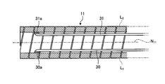
- FIG. 3 is a partial cross-sectional view showing the configuration of a main part of the guide sheath according to the first embodiment of the present invention. 3, the operation unit 20, a cut half portion cross-section (a half cross-section) Figure a plane including the longitudinal axis N 1 parallel and the longitudinal axis N 1 of the guide sheath 1 illustrated in Figure 1.
- FIG. 3 is a view in which the covering member 13 of the insertion portion 10 is removed from the guide sheath 1 shown in FIG.
- the contour lines of the strands located behind the cut surface are omitted.
- the guide sheath 1 extends in a tubular shape, and a part of the guide sheath 1 is inserted into a hole formed on the body surface of the subject. After that, an endoscope or a treatment device is inserted into the guide sheath 1, and observation and treatment in the subject are performed.
- the guide sheath 1 has a tubular shape, an insertion portion 10 to be inserted into the subject, a tubular operation portion 20 connected to the proximal end side of the insertion portion 10 and operating the bending mode of the insertion portion 10. To be equipped.
- the insertion portion 10 and the operation portion 20 are formed with through holes that communicate with each other.
- the central axis of the through hole of the unbent insertion portion 10 and the central axis of the through hole of the operating portion 20 coincide with the longitudinal axis N 1 of the guide sheath 1, respectively.
- the operation portion 20 side in the longitudinal direction is referred to as a base end (end) side, and the opposite side thereof is referred to as a tip end (front end) side.
- the insertion portion 10 has a tip portion 101 provided on the tip end side, a curved portion 102 extending from the tip end portion 101 toward the proximal end side and curving in a predetermined direction, and a curved portion 102 to the opposite side of the tip portion 101 (operation). It has a base end portion 103 extending to the portion 20 side).
- the insertion portion 10 has a coil 11 formed by spirally winding a wire extending while maintaining a rectangular cross section with chamfered corners.
- the coil 11 has the same winding angle or an angle within a preset range.
- the strands that make up the coil 11 have elasticity.
- the operation unit 20 is formed with an opening 21 through which an endoscope and a treatment device are inserted.
- the operation unit 20 has an operation lever 22 that bends the curved portion 102 in a predetermined direction.
- the operating portion 20 is formed with a regulating groove 23 extending in the longitudinal axis N 1 direction of the guide sheath 1 and restricting the moving range of the operating lever 22.
- the regulation groove 23 has a wavy side surface extending in the longitudinal axis N 1 direction, and a portion having a large opening width (first portion) and a portion having a small opening (second portion) are continuously formed in the longitudinal axis N 1 direction. Makes a repeating shape.
- the operating lever 22 moves in the longitudinal axis N 1 direction of the guide sheath 1 following the regulation groove 23.
- the operation lever 22 has a configuration for locking into the second portion while moving stepwise in restricting groove 23 You can change the placement and stop at that position.
- the operation lever 22 is turned to be screwed and fixed to the main body of the operation unit 20.
- the operation unit 20 is gripped by an operator such as a doctor during use.
- One end (tip 301) of the guide sheath 1 is fixed to the inner peripheral surface of the front end 111a of the coil 11 (here, the inner surface of the wire of the coil 11), and the other end (end 302) is operated.
- An operation rod 30 connected to the lever 22 is provided.
- the operating rod 30 has a uniform rectangular cross section and an extended strip shape.
- Operating rod 30 extends along the circumferential direction of the generating line L 1 of the coil 11.
- the generatrix here refers to a straight line substantially parallel to the spiral axis N 11 direction of the coil 11 on the pillar surface formed by the outer diameter curved surface of the coil 11.
- the operation rod 30 moves in the longitudinal axis N 1 direction in conjunction with the movement of the operation lever 22.
- the operating rod 30 is fixed to the tip of the coil 11 by the fixing portion 30a.
- the fixed portion 30a is formed by, for example, laser welding, brazing, soldering, adhesion, resistance welding, or the like.
- the operation rod 30 is fixed to the operation lever 22 by a known fastening means such as screw tightening.
- the operating rod 30 corresponds to the advancing / retreating transmitting means, and is formed by using a flexible and elastic material such as stainless steel.
- a curved pipe unit is formed by the coil 11 and the operating rod 30.
- the coil 11 is formed by winding a wire around a spiral shaft N 11. Specifically, the coil 11 has a close-contact winding structure in which adjacent strands come into contact with each other in the direction of the spiral axis N 11.
- the coil 11 corresponds to the first hard coil portion 111 extending corresponding to the forming region of the tip portion 101, the curved coil portion 112 extending corresponding to the forming region of the curved portion 102, and the forming region of the base end portion 103. It has a second hard coil portion 113 extending thereafter (see FIG. 3).
- the tip end side in the spiral axis N 11 direction corresponds to one end side
- the proximal end side corresponds to the other end side.
- the spiral shaft N 11 coincides with the longitudinal shaft N 1 when the coil 11 is assembled as the guide sheath 1.
- the covering member 13 suppresses damage to an organ or the like in the subject due to the unevenness formed by the coil 11.
- the covering member 13 has a first covering portion 131 formed at a position corresponding to the tip portion 101, a bellows-shaped expanding / contracting portion 132 formed at a position corresponding to the curved portion 102, and a position corresponding to the base end portion 103. It has a second covering portion 133 formed in.
- the covering member 13 is formed by using a stretchable material such as a rubber material.
- the operating rod 30 has a width that does not allow the operating rod 30 to buckle when the operating lever 22 is pushed in, based on the force of the coil 11 (spring constant) and the force for expanding and contracting the telescopic portion 132 of the covering member 13. Set to thickness. The operating rod 30 bends following the curvature of the curved coil portion 112.
- FIG. 4 is a cross-sectional view illustrating the insertion portion 10 in a state where the curved portion 102 is curved.
- the operating rod 30 When the operating rod 30 is pushed toward the insertion portion 10 side (tip side) by the movement of the operating lever 22, it is pulled by the first hard coil portion 111 and the coil 11 is expanded. At this time, the coil 11 is deformed by expanding some of the strands in response to the pulling of the operating rod 30. Further, the expansion / contraction portion 132 expands / contracts due to the bending of the curved coil portion 112. At this time, by locking the operating lever 22 in the regulation groove 23, the curved state of the curved portion 102 can be maintained.
- the load applied to the pushing of the operating rod 30 can be adjusted by changing the thickness, width, and material (elastic modulus, etc.) of the strip-shaped operating rod 30 that extends while maintaining a rectangular cross section.
- a curved tube (a curved tube ( Here, the coil 11) can be easily assembled, and the curved pipe can be handled as a unit, so that the labor of assembling work can be reduced.
- the operation rod 30 since the band-shaped operation rod 30 extending while maintaining the rectangular cross section enables the bending operation, the operation rod 30 passes in the width direction (here, the longitudinal axis N 1). Deformation in the direction orthogonal to the plane) is suppressed, and blurring in the direction perpendicular to the bending direction can be suppressed.
- the bending mechanism is formed by using the coil 11 formed by winding the wire, the number of parts is reduced as compared with the configuration in which the insertion portion is curved by a plurality of angle rings.
- the structure can be simplified and the insertion portion can be easily assembled.
- FIG. 5 is a cross-sectional view illustrating the configuration of a main part of the coil of the insertion portion in the guide sheath according to the first modification of the first embodiment of the present invention.
- the number of operating rods arranged is different from that of the first embodiment described above.
- the configuration is the same as that of the first embodiment.
- a configuration different from the above-described first embodiment will be described.
- the guide sheath according to the first modification is provided with an operation rod 31 having one end fixed to the inner peripheral surface of the coil 11 and the other end connected to the operation lever 22.
- the operating rod 31 has a strip shape that extends while maintaining a rectangular cross section.
- the operating rod 31 extends along the generatrix L 2 in the circumferential direction of the coil 11.
- the bus L 2 is a bus located on the opposite side of the spiral axis N 11 from the bus L 1.
- the operating rods 30 and 31 are provided around the spiral axis N 11 along the vicinity of each generatrix having an equal division angle in the circumferential direction of the coil 11.
- Operating rod 31, similarly to the operation rod 30, in conjunction with the movement of the operating lever 22 moves in the longitudinal axis N 1 direction.
- the operation rod 31 is fixed to the tip of the coil 11 by the fixing portion 31a.
- the fixing portion 31a is formed by, for example, laser welding, brazing, soldering, adhesion, resistance welding, or the like.
- the operation rod 31 is fixed to the operation lever 22 by a known fastening means such as screw tightening.
- the operating rod 31 is formed using a flexible and elastic material such as stainless steel.
- the curved pipe unit is composed of the coil 11 and the operating rods 30 and 31.
- the curved pipe (here, the coil 11) can be easily assembled and curved as in the first embodiment described above. Since the pipe can be handled as a unit, the labor of assembling work can be reduced. Further, according to the first modification, since the band-shaped operating rods 30 and 31 extending while maintaining the rectangular cross section enable the bending operation, the deformation of the operating rod 30 in the width direction is suppressed and the operating rod 30 is bent in the bending direction. On the other hand, vertical shake can be suppressed. The bending operation at this time can be curved in two directions in addition to the bending operation of the first embodiment.
- FIG. 6 is a cross-sectional view illustrating the configuration of a main part of the coil of the insertion portion in the guide sheath according to the second modification of the first embodiment of the present invention.
- a guide for guiding the insertion of the operating rod 30 into the coil 11 is provided for the configuration of the first embodiment described above.
- the configuration other than the guide is the same as that of the first embodiment.
- a configuration (guide 14) different from the above-described first embodiment will be described.
- the guide 14 is provided inside the coil 11 in a rectangular shape in which the operation rod 30 is slidable, following the cross-sectional shape of the operation rod 30.
- the guide 14 guides the insertion direction of the operation rod 30 by inserting the operation rod 30.
- a plurality of guides 14 are attached to the coil 11.
- the guide 14 is joined to the inside of the coil 11 every preset number of turns.
- the guide 14 is joined to the coil 11 by laser welding, brazing, soldering, bonding, resistance welding, or the like.
- the guide 14 guides the operation rod 30 so that the insertion position of the operation rod 30 with respect to the coil 11 can be obtained. It is possible to suppress slippage and buckling.
- the buckling of the operating rod 30 can be suppressed by increasing the number of guides 14 and reducing (narrowing) the arrangement interval of the guides 14.
- FIG. 7 is a cross-sectional view illustrating the configuration of a main part of the coil of the insertion portion in the guide sheath according to the third modification of the first embodiment of the present invention.
- a guide for guiding the insertion of the operating rod 30 into the coil 11 is provided for the configuration of the first embodiment described above.
- the configuration other than the guide is the same as that of the first embodiment.
- a configuration (guide 15) different from the above-described first embodiment will be described.
- the guide 15 is provided on the outside of the coil 11 in a rectangular shape in which the operation rod 30 is slidable, following the cross-sectional shape of the operation rod 30.
- the guide 15 guides the insertion direction of the operation rod 30 by inserting the operation rod 30.
- a plurality of guides 15 are attached to the coil 11.
- the guide 15 is joined to the outer peripheral side of the coil 11 every preset number of turns.
- the guide 15 is joined to the coil 11 by laser welding, brazing, soldering, bonding, resistance welding, or the like.
- the guide 15 guides the operation rod 30 so that the insertion position of the operation rod 30 with respect to the coil 11 can be obtained. It is possible to suppress slippage and buckling.
- FIG. 8 is a partial cross-sectional view illustrating the configuration of a main part of the coil of the insertion portion in the guide sheath according to the second embodiment of the present invention.
- the second embodiment is different from the first embodiment described above in that a part of the coil is joined.
- the configuration is the same as that of the first embodiment.
- a configuration different from the above-described first embodiment will be described.
- the coil 11 according to the second embodiment is formed by joining a part of adjacent strands in the direction of the spiral axis N 11.
- the coil 11 is formed with a plurality of elastic joint portions 121 provided side by side in the spiral axis N 11 direction.
- the elastic joint portion 121 is composed of an elastic body that joins adjacent strands in the spiral axis N 11 direction.
- the elastic body is formed by, for example, laser welding.
- Each elastic joint 121 is provided along the bus L 11.
- elastic bodies may be formed by brazing, soldering, bonding, resistance welding, or the like to join the strands together.
- the wires of the coil 11 are bridged by an adherend melted by itself or an adherend such as wax, solder, or an adhesive.
- the elastic joint 121 constitutes a curvature adjusting means.
- FIG. 9 is a cross-sectional view illustrating the insertion portion 10 in a state where the curved portion 102 is curved.
- FIG. 10 is an enlarged cross-sectional view of a part of the coil shown in FIG.
- FIG. 9 shows the coil 11 of the insertion portion 10 in a state where the curved portion 102 is curved.
- the elastic joint portion may be illustrated as a representative of the formed region, omitting each elastic body.
- the wires of the coil 11 are fixed by the elastic joint 121, the wires of the coil 11 do not widen at this portion.
- the gap between the strands of the portion where the elastic joint portion 121 is not formed is widened and deformed.
- the coil 11 is bent by the elastic joint portion 121 so that the distance between the strands on the side through which the operation rod 30 is inserted is widened.
- the expansion / contraction portion 132 expands / contracts due to the bending of the curved coil portion 112.
- the load applied to the pushing of the operating rod 30 can be adjusted by changing the thickness, width, and material (elastic modulus, etc.) of the strip-shaped operating rod 30 extending while maintaining the rectangular cross section.
- the bending direction of the bending portion 102 is controlled by joining a part of the strands of the coil 11.
- a curved pipe (a curved pipe) is allowed to be curved by a coil 11 composed of one member wound with a wire.
- the coil 11) can be easily assembled, and the curved pipe can be handled as a unit, so that the labor of assembling work can be reduced.
- the band-shaped operating rod 30 extending while maintaining the rectangular cross section enables the bending operation, the deformation of the operating rod 30 in the width direction is suppressed, and the bending direction is suppressed. It is possible to suppress vertical shake.
- the spiral axis N It may be continuous in a direction inclined with respect to 11, or may be formed so as to spirally extend with respect to the outer circumference of the coil 11.
- FIG. 11 is a partial cross-sectional view illustrating the configuration of a main part of the coil of the insertion portion in the guide sheath according to the third embodiment of the present invention.
- the third embodiment differs from the second embodiment described above in that an elastic joint formed in the coil is added. Other than this, the configuration is the same as that of the second embodiment.
- a configuration different from that of the second embodiment described above will be described.
- the coil 11 according to the third embodiment is formed by joining a part of adjacent strands in the direction of the spiral axis N 11.
- the coil 11 is formed with a plurality of elastic joint portions 121 provided side by side in the spiral axis N 11 direction.
- the elastic joint 121 is provided along the spiral axis N 11 at varying frequencies.
- the elastic joint portion 121 is made of an elastic body that joins adjacent strands in the spiral axis N 11 direction.
- elastic joint portions 121 are formed on the bus L 11 to the bus L 14 which are different from each other (the bus L 14 is not shown).
- the elastic joint portion 121 is formed on the bus L 11.
- the bus L 12 faces the bus L 11 with respect to the spiral axis N 11.
- Bus lines L 13 and L 14 are bus lines formed at different positions on a second plane orthogonal to the first plane passing through the bus L 11 and the bus L 12.
- an elastic joint portion 121 is formed in one place for one winding of the wire of the coil 11.
- elastic joints 121 are formed at at least two positions for one winding of the wire of the coil 11 at positions corresponding to the first hard coil portion 111 and the second hard coil portion 113.
- One winding of the wire here corresponds to one pitch in which the wire is wound around the spiral axis N 11.
- FIG. 12 is a cross-sectional view illustrating the insertion portion 10 in a state where the curved portion 102 is curved.
- the operation rod 30 When the operation rod 30 is pushed toward the insertion portion 10 side (tip side) by the movement of the operation lever 22, it is pulled by the first hard coil portion 111, and the space between the wires of the coil 11 is expanded. At this time, since the wires of the coil 11 are fixed by the elastic joint 121, the wires do not widen at this portion. In the coil 11, the gap between the strands of the portion where the elastic joint portion 121 is not formed is widened and deformed.
- the coil 11 is bent by the elastic joint portion 121 in the region corresponding to the curved coil portion 112 so that the strands on the side through which the operation rod 30 is inserted (opposite to the bus L 11) are widened. ..
- the curved coil portion 112 is bent in a state where the strands are connected to each other by the elastic joint portion 121 (see, for example, FIG. 10).
- the expansion / contraction portion 132 expands / contracts due to the bending of the curved coil portion 112.
- the curved portion 102 bends according to the pushing amount of the operating rod 30.
- the bending mode of the curved portion 102 can be adjusted by changing the pushing amount of the operating rod 30. .. Specifically, if the operating rod 30 is further pushed in, the radius of curvature R1 becomes smaller, and if the amount of pushing is reduced, the radius of curvature R1 becomes larger.
- the bending mode of the curved portion 102 can be adjusted by changing the forming range of the elastic joint portion 121 in the coil 11, the thickness of the wire (thickness or width if the cross section is rectangular), and the material (elastic modulus, etc.). Further, the load applied to the pushing of the operating rod 30 can be adjusted by changing the thickness, width, and material (elastic modulus, etc.) of the strip-shaped operating rod 30 extending while maintaining the rectangular cross section.
- FIGS. 13A to 13D are views for explaining a method of manufacturing a coil in the guide sheath according to the third embodiment of the present invention.
- one joining line 120 is formed by laser welding from one end to the other end of the coil 11 in the spiral axis N 11 direction with respect to the tightly wound coil 11 (see FIG. 13A) (see FIG. 13B).
- Joint line 120 is formed, for example, continuously plurality of elastic joint with laser light while moving the irradiation position of the laser light to the helix axis N 11 intermittently irradiated (elastic body).
- the joining wire 120 is a first side portion 110a provided in one (part) of the circumferential direction of the coil 11, and is formed on the first side portion 110a along the bus line B 11 in the spiral axis N 11 direction. Will be done.
- the bus B 11 corresponds to the bus L 11 described above.
- the laser beam is emitted using a device capable of controlling the oscillation period in units of nanoseconds to several seconds. Further, the laser beam is preferably generated by using a device capable of controlling the irradiation region, such as a fiber laser, from the viewpoint of controlling the welding position and the welding region.
- an elastic body 121a forming a part of the elastic joint portion 121A is formed, and then a plurality of elastic bodies 121a are formed according to the arrangement positions of the first hard coil portion 111 and the second hard coil portion 113.
- An elastic joint 121 is formed (see FIG. 13C).
- Each elastic joint portion 121 is formed by intermittently irradiating the laser beam, for example, while moving the irradiation position of the laser beam in parallel with the spiral axis N 11. At this time, the laser beam is not irradiated at the position where the irradiation position of the laser beam corresponds to the formation region of the curved coil portion 112.
- each elastic joint is formed by irradiating the laser beam while rotating the laser emission position or the coil at a preset angle (for example, 90 °).
- a preset angle for example, 90 °
- four elastic bodies are arranged in the circumferential direction in one winding of the wire.
- six joints are arranged in the circumferential direction.
- the elastic joint portion 121 constitutes a hard coil portion that restrains the separation of the strands.
- the operating rod 30 is inserted into the coil 11 and the tip of the operating rod 30 is fixed inside (front end portion) of the first hard coil portion 111 (see FIG. 13D).
- the operating rod 30 is arranged along the second side portion 110b facing the first side portion 110a with the spiral shaft N 11 interposed therebetween.
- Second side 110b are provided along a generatrix B 12 opposed to the bus B 11 across the helical axis N 11 parallel and helical axis N 11. That is, the operating rod 30 extends along the second side portion 110b in the coil 11.
- This bus B 12 corresponds to the bus L 12 described above.
- the operation unit 20 After arranging the operation rod 30 on the coil 11, the operation unit 20 is attached to the coil 11 and the operation rod 30 is fixed to the operation lever 22. After that, the guide sheath 1 is manufactured by covering the outer circumference of the coil 11 with the covering member 13.
- the bending direction of the bending portion 102 is controlled by adjusting the joining position of the strands of the coil 11 (the forming position of the elastic joining portion 121).
- a curved pipe (a curved pipe) is allowed to be curved by a coil 11 composed of one member wound with a wire.
- the coil 11) can be easily assembled, and the curved pipe can be handled as a unit, so that the labor of assembling work can be reduced.
- the width direction of the operating rod 30 (here, the longitudinal axis N 1 , the first). Deformation of the side portion 110a and the direction orthogonal to the plane passing through the second side portion 110b) can be suppressed, and the shake in the direction perpendicular to the bending direction can be suppressed.
- the bending mechanism is formed by using the coil 11 formed by winding the wire, the number of parts is reduced as compared with the configuration in which the insertion portion is curved by a plurality of angle rings.
- the structure can be simplified and the insertion portion can be easily assembled.
- the spiral axis N 11 It may be continuous in a direction inclined with respect to the coil 11, or may be formed so as to spirally extend with respect to the outer circumference of the coil 11.
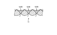
- FIG. 14 is a cross-sectional view illustrating the configuration of a main part of the coil of the insertion portion in the guide sheath according to the first modification of the third embodiment of the present invention.
- the joining mode of the joining portion is different from that of the third embodiment described above.
- the configuration other than the joining mode of the joining portion is the same as that of the third embodiment.
- a configuration (elastic joint) different from that of the first embodiment described above will be described.
- the elastic joint portion 121B is formed on the coil 11 according to the first modification.
- the elastic joint portion 121A is composed of, for example, a continuous elastic body formed by melting and solidifying a wire by a laser beam.
- the elastic joint portion 121A extends in the direction of the spiral axis N 11 of the coil 11.
- the elastic joint portion 121A is formed, for example, by repeating spot welding in the spiral axis N 11 direction.
- the elastic joint portion 121A is formed by irradiating a laser beam while overlapping welding regions adjacent to each other in the spiral axis N 11 direction. In addition to laser welding, brazing, soldering, adhesion, resistance welding, or the like may be adopted.
- the joining mode of the third embodiment described above and the joining mode of the modified example 1 may be appropriately combined according to the joining portion.
- the mode of intermittently forming the elastic joint portion described in the third embodiment is applied to the region corresponding to the curved coil portion
- the mode of continuously welding described in the first modification is the first rigid.
- the configuration may be applied to the region corresponding to the coil portion and the second hard coil portion.
- FIG. 15 is a cross-sectional view illustrating the configuration of the insertion portion in the guide sheath according to the second modification of the third embodiment of the present invention.
- the cross-sectional shape of the wire of the coil is different from that of the third embodiment described above.
- the configuration other than the cross-sectional shape of the coil is the same as that of the third embodiment.
- a configuration (coil) different from that of the third embodiment described above will be described.
- the coil 11A is formed by winding a wire extending while maintaining a circular cross section. Similar to the first embodiment, the coil 11A is formed with an elastic joint portion 121B for joining adjacent strands in the spiral axis N 11 direction.
- the elastic joint portion 121B is composed of, for example, a plurality of elastic bodies formed by melting and solidifying between the strands by a laser beam. When a welded portion is formed between the strands having a circular cross section, a radial welded portion in which the melt has entered the gap between the strands is formed.
- the elastic joint portion 121B is formed by continuously forming an elastic body in the spiral axis N 11 direction. In addition to laser welding, the strands may be joined by brazing, soldering, bonding, resistance welding, or the like.
- FIG. 16 is a diagram illustrating a configuration of a coil at an insertion portion in the guide sheath according to the fourth embodiment of the present invention.
- the bending mode of the curved portion at the insertion portion is different from the configuration of the third embodiment described above.
- a configuration different from that of the third embodiment described above will be described.
- the coil 11 and the operation rod 30 are shown, and the state in which the coil 11 is curved is shown.
- the coil 11 has a close-contact winding structure in which adjacent strands come into contact with each other in a direction extending by winding (corresponding to the spiral axis N 11 direction described above).
- the coil 11 corresponds to the first hard coil portion 111 extending corresponding to the forming region of the tip portion 101, the curved coil portion 112A extending corresponding to the forming region of the curved portion 102, and the forming region of the base end portion 103. It has a second hard coil portion 113 extending thereafter.
- the curved coil portion 112A is partially joined by the elastic joint portion 121 and partially joined by the elastic joint portion 121 to the first curved coil portion 112A-1 that deforms in a predetermined direction, and the first curved coil portion 112A is partially joined. It has a second curved coil portion 112A-2 that is deformed with a larger radius of curvature than the portion 112A-1.
- each curved coil portion is composed of an elastic body that joins a preset number of strands and a position between the strands.
- Each elastic joint is formed by melting and solidifying between the strands by a laser beam.
- a plurality of elastic joint portions 121 are intermittently arranged in one turn with respect to the direction of the spiral axis N 11.
- the elastic joint bridges two strands.
- the strands may be joined by brazing, soldering, bonding, resistance welding, or the like.
- the operation rod 30 When the operation rod 30 is pushed toward the insertion portion 10 side (left side in FIG. 16) by the movement of the operation lever 22, it is pulled by the first hard coil portion 111, and the space between the wires of the coil 11 is expanded. At this time, since the wires are fixed to the coil 11 by the elastic joint 121, the wires do not widen in this portion.
- the wire between the first hard coil portion 111 and the second hard coil portion 113 where the elastic body 121a and the elastic body 121g are not formed is widened and deformed.
- the first curved coil portion 112A-1 the intervals between the strands of the portions not joined by the elastic joining portion 121 are widened and bent.
- the second curved coil portion 112A-2 the intervals between the strands of the portions not joined by the elastic joining portion 121 are widened and bent.
- the first curved coil portion 112A-1 is curved in an arc shape having a radius of curvature R2 centered on the point P2, and the second curved coil portion 112A-2 is a point.
- the strands are partially joined by the elastic body 121g in addition to the elastic body 121a. Therefore, the radius of curvature R2 is smaller than the radius of curvature R3.
- the bending direction of the bending portion 102 is controlled by adjusting the joining position of the strands of the coil 11.
- the curved tube is formed in order to enable a state in which the insertion portion is curved by a coil 11 composed of one member wound with a wire. Since it can be easily assembled and the curved pipe can be handled as a unit, the labor of assembling work can be reduced. Further, since the band-shaped rod extending while maintaining the rectangular cross section enables the bending operation, the deformation in the rod width direction can be suppressed, and the shake in the direction perpendicular to the bending direction can be suppressed.
- the bending mechanism is formed by using the coil 11 formed by winding the wire, the number of parts is reduced as compared with the configuration in which the insertion portion is curved by a plurality of angle rings.
- the structure can be simplified and the insertion portion can be easily assembled.
- the bending mode is different.
- the curved shape is changed or the radius of curvature is changed by changing the joint portion in the deformed portion (for example, the number of strands that the elastic joint portion 121 bridges in the second curved coil portion 112A-2). Can be partially adjusted.
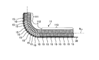
- FIG. 17 is a diagram illustrating a configuration of a coil at an insertion portion in the guide sheath according to the fifth embodiment of the present invention.
- the bending mode of the curved portion in the insertion portion is different from the configuration of the first embodiment described above.
- FIG. 17 shows the coil 11 and the operating rod 30 in a curved state.
- the coil 11 has a close-contact winding structure in which adjacent strands come into contact with each other in the direction extending by winding (the spiral axis N 11 direction described above).
- the coil 11 extends from the first hard coil portion 111 provided on the base end side of the insertion portion, the first hard coil portion 111 provided on the tip end side of the insertion portion, and the first hard coil portion 111, and operates. From the first curved coil portion 114 that is deformed by the displacement of the rod 30, the intermediate hard coil portion 115 extending from the first curved coil portion 114 to the side opposite to the first hard coil portion 111 side, and the intermediate hard coil portion 115.
- the portion corresponding to the intermediate hard coil portion 115 may have a shape that does not expand or contract (not bellows).
- the coil 11 is formed by joining a part of adjacent strands in the axial direction (corresponding to the spiral axis N 11 direction described above) extending by winding. Specifically, the coil 11 is formed with the elastic joint portion 121 described above. Specifically, in the first hard coil portion 111, the second hard coil portion 113, and the intermediate hard coil portion 115, a plurality of elastic joint portions 121 are formed in one winding of the wire, and the separation of the wires is restricted. There is. On the other hand, in the first curved coil portion 114 and the second curved coil portion 116, one elastic joint portion 121 is formed along a common bus (for example, bus L 11) in one winding of the wire. Each elastic joint is composed of a plurality of elastic bodies formed by melting and solidifying between the strands by a laser beam. In addition to laser welding, the strands may be joined by brazing, soldering, bonding, resistance welding, or the like.
- the operation rod 30 When the operation rod 30 is pushed toward the insertion portion 10 side (left side in FIG. 17) by the movement of the operation lever 22, it is pulled by the first hard coil portion 111 and the coil 11 is expanded. At this time, since the wires are fixed to the coil 11 by the elastic joint 121, the wires do not widen in this portion. In the coil 11, the wires of the first curved coil portion 114 and the second curved coil portion 116 where the elastic joint portion 121 is not formed are widened and deformed.
- the first curved coil portion 114 is curved in an arc shape having a radius of curvature R4 centered on the point P4, and the second curved coil portion 116 has a radius of curvature centered on the point P5. It curves in the shape of an arc of R5.
- the width of the wire here, the length of the wire in the spiral axis direction of the coil
- the number of turns are the same, the radius of curvature R4 and the radius of curvature R5 are the same.
- the bending direction of the bending portion 102 is controlled by adjusting the joining position of the strands of the coil 11.
- the curved tube is formed in order to enable a state in which the insertion portion is curved by a coil 11 composed of one member wound with a wire. Since it can be easily assembled and the curved pipe can be handled as a unit, the labor of assembling work can be reduced. Further, since the band-shaped rod extending while maintaining the rectangular cross section enables the bending operation, the deformation in the rod width direction can be suppressed, and the shake in the direction perpendicular to the bending direction can be suppressed.
- the bending mechanism is formed by using the coil 11 formed by winding the wire, the number of parts is reduced as compared with the configuration in which the insertion portion is curved by a plurality of angle rings.
- the structure can be simplified and the insertion portion can be easily assembled.
- the first curved coil portion 114 and the second curved coil portion 116 to which the strands are partially joined by the elastic joining portion 121 are interposed of the intermediate hard coil portion 115 to form the coil 11. It was constructed by arranging them in the spiral axis direction.
- the curved shape can be changed or the radius of curvature can be partially adjusted by providing the deformed portion via the intermediate hard coil portion 115. Further, if a plurality of intermediate hard portions are provided and curved portions are provided at both ends thereof, the curved portions can be curved in multiple stages.
- the present invention should not be limited only to the above-described embodiments.
- the configuration of a medical guide sheath for puncturing a subject has been described as an example, but it can also be used as an industrial guide sheath for puncturing a structure and observing the inside. it can.
- the welding method is not limited to this.
- known welding techniques such as arc welding, spot welding, and electron beam welding.
- the elastic joint portion in which the welded portion formed by melting the strands themselves joins the strands as an elastic body has been described. If so, the strands may be joined to each other using a material different from the strands, for example, the above-mentioned brazing, solder, adhesive, or the like. Further, as the elastic joint portion, an example of joining adjacent strands in the spiral axis N 11 direction by one elastic body has been described, but a plurality of elastic bodies may be formed in one elastic joint portion. ..
- the elastic joint is composed of a plurality of elastic bodies (for example, elastic bodies 121a)
- the coil can be prevented from bending, it is elastic in at least one place. It may be a structure in which a body is formed.
- the elastic body is not limited to the one extending parallel to the spiral axis, and may be, for example, one extending in a spiral shape.
- the present invention may include various embodiments within a range that does not deviate from the technical idea described in the claims.
- the curved tube unit of the medical guide sheath according to the present invention is useful for easily assembling the curved tube and reducing the labor of assembling the curved tube.
Landscapes
- Health & Medical Sciences (AREA)
- Life Sciences & Earth Sciences (AREA)
- Engineering & Computer Science (AREA)
- General Health & Medical Sciences (AREA)
- Biomedical Technology (AREA)
- Veterinary Medicine (AREA)
- Public Health (AREA)
- Animal Behavior & Ethology (AREA)
- Heart & Thoracic Surgery (AREA)
- Surgery (AREA)
- Biophysics (AREA)
- Pulmonology (AREA)
- Hematology (AREA)
- Anesthesiology (AREA)
- Molecular Biology (AREA)
- Pathology (AREA)
- Medical Informatics (AREA)
- Nuclear Medicine, Radiotherapy & Molecular Imaging (AREA)
- Physics & Mathematics (AREA)
- Optics & Photonics (AREA)
- Radiology & Medical Imaging (AREA)
- Mechanical Engineering (AREA)
- Endoscopes (AREA)
Priority Applications (4)
| Application Number | Priority Date | Filing Date | Title |
|---|---|---|---|
| CN201980102677.7A CN114760942A (zh) | 2019-12-05 | 2019-12-05 | 医疗用引导护套的弯曲管单元 |
| JP2021562291A JPWO2021111592A1 (https=) | 2019-12-05 | 2019-12-05 | |
| PCT/JP2019/047643 WO2021111592A1 (ja) | 2019-12-05 | 2019-12-05 | 医療用ガイドシースの湾曲管ユニット |
| US17/742,700 US20220265964A1 (en) | 2019-12-05 | 2022-05-12 | Bent tube unit of medical guide sheath |
Applications Claiming Priority (1)
| Application Number | Priority Date | Filing Date | Title |
|---|---|---|---|
| PCT/JP2019/047643 WO2021111592A1 (ja) | 2019-12-05 | 2019-12-05 | 医療用ガイドシースの湾曲管ユニット |
Related Child Applications (1)
| Application Number | Title | Priority Date | Filing Date |
|---|---|---|---|
| US17/742,700 Continuation US20220265964A1 (en) | 2019-12-05 | 2022-05-12 | Bent tube unit of medical guide sheath |
Publications (1)
| Publication Number | Publication Date |
|---|---|
| WO2021111592A1 true WO2021111592A1 (ja) | 2021-06-10 |
Family
ID=76221566
Family Applications (1)
| Application Number | Title | Priority Date | Filing Date |
|---|---|---|---|
| PCT/JP2019/047643 Ceased WO2021111592A1 (ja) | 2019-12-05 | 2019-12-05 | 医療用ガイドシースの湾曲管ユニット |
Country Status (4)
| Country | Link |
|---|---|
| US (1) | US20220265964A1 (https=) |
| JP (1) | JPWO2021111592A1 (https=) |
| CN (1) | CN114760942A (https=) |
| WO (1) | WO2021111592A1 (https=) |
Cited By (1)
| Publication number | Priority date | Publication date | Assignee | Title |
|---|---|---|---|---|
| EP4429746A4 (en) * | 2021-11-08 | 2025-10-22 | Technion Res & Dev Foundation | RECONFIGURABLE STEERABLE CATHETER |
Families Citing this family (4)
| Publication number | Priority date | Publication date | Assignee | Title |
|---|---|---|---|---|
| CN116234508A (zh) | 2020-06-05 | 2023-06-06 | 伊纳里医疗有限公司 | 可再捕获的漏斗导管以及相关联的系统和方法 |
| WO2022109034A1 (en) * | 2020-11-18 | 2022-05-27 | Inari Medical, Inc. | Catheters having steerable distal portions, and associated systems and methods |
| US12279970B2 (en) * | 2022-06-10 | 2025-04-22 | Globus Medical Inc. | Articulating graft delivery |
| CN118402746B (zh) * | 2024-02-19 | 2025-07-18 | 瑞龙诺赋(上海)医疗科技有限公司 | 一种应用于腔道内镜外套管的弯曲信息确定方法 |
Citations (3)
| Publication number | Priority date | Publication date | Assignee | Title |
|---|---|---|---|---|
| JPS62253041A (ja) * | 1986-04-25 | 1987-11-04 | オリンパス光学工業株式会社 | 内視鏡用処置具 |
| JP2008531086A (ja) * | 2005-02-22 | 2008-08-14 | カーディオフォーカス・インコーポレイテッド | 可撓性シースカテーテル |
| WO2013038813A1 (ja) * | 2011-09-12 | 2013-03-21 | オリンパスメディカルシステムズ株式会社 | 医療用コイルおよびその製造方法、ならびに医療機器 |
Family Cites Families (8)
| Publication number | Priority date | Publication date | Assignee | Title |
|---|---|---|---|---|
| US5125395A (en) * | 1990-09-12 | 1992-06-30 | Adair Edwin Lloyd | Deflectable sheath for optical catheter |
| JP4560455B2 (ja) * | 2005-08-01 | 2010-10-13 | オリンパスメディカルシステムズ株式会社 | 内視鏡 |
| CA2628417C (en) * | 2005-11-08 | 2014-07-08 | Custom Medical Applications, Inc. | Reinforced catheter with articulated distal tip |
| JP2011206175A (ja) * | 2010-03-29 | 2011-10-20 | Terumo Corp | ガイドワイヤ |
| US20140052109A1 (en) * | 2012-08-19 | 2014-02-20 | Diros Technology Inc. | Steerable Multifunction Catheter Probe with High Guidability and Reversible Rigidity |
| WO2014157001A1 (ja) * | 2013-03-26 | 2014-10-02 | オリンパス株式会社 | 処置具 |
| EP2979650B1 (en) * | 2013-03-28 | 2019-04-10 | Olympus Corporation | Mantle tube and treatment tool |
| EP3344323B1 (en) * | 2015-09-04 | 2019-02-27 | Petrus A. Besselink | Flexible and steerable device |
-
2019
- 2019-12-05 JP JP2021562291A patent/JPWO2021111592A1/ja active Pending
- 2019-12-05 CN CN201980102677.7A patent/CN114760942A/zh active Pending
- 2019-12-05 WO PCT/JP2019/047643 patent/WO2021111592A1/ja not_active Ceased
-
2022
- 2022-05-12 US US17/742,700 patent/US20220265964A1/en not_active Abandoned
Patent Citations (3)
| Publication number | Priority date | Publication date | Assignee | Title |
|---|---|---|---|---|
| JPS62253041A (ja) * | 1986-04-25 | 1987-11-04 | オリンパス光学工業株式会社 | 内視鏡用処置具 |
| JP2008531086A (ja) * | 2005-02-22 | 2008-08-14 | カーディオフォーカス・インコーポレイテッド | 可撓性シースカテーテル |
| WO2013038813A1 (ja) * | 2011-09-12 | 2013-03-21 | オリンパスメディカルシステムズ株式会社 | 医療用コイルおよびその製造方法、ならびに医療機器 |
Cited By (1)
| Publication number | Priority date | Publication date | Assignee | Title |
|---|---|---|---|---|
| EP4429746A4 (en) * | 2021-11-08 | 2025-10-22 | Technion Res & Dev Foundation | RECONFIGURABLE STEERABLE CATHETER |
Also Published As
| Publication number | Publication date |
|---|---|
| CN114760942A (zh) | 2022-07-15 |
| US20220265964A1 (en) | 2022-08-25 |
| JPWO2021111592A1 (https=) | 2021-06-10 |
Similar Documents
| Publication | Publication Date | Title |
|---|---|---|
| WO2021111592A1 (ja) | 医療用ガイドシースの湾曲管ユニット | |
| US9204783B2 (en) | Elongate medical device with articulating portion | |
| EP2564756B1 (en) | Endoscope | |
| US8636270B2 (en) | Structure for use as part of a medical device | |
| CN103402417B (zh) | 内窥镜的挠性管部及具有该挠性管部的内窥镜 | |
| JP6411745B2 (ja) | 医療機器 | |
| JP7502031B2 (ja) | 医療用マニピュレーターの可撓チューブ及び屈曲構造体 | |
| US20090253958A1 (en) | Endoscope, connection method of bending section and flexible section in endoscope, production method of endoscope provided for this connection method, endoscope overtube, connection method of bending section and flexible section in endoscope overtube and production method of endoscope overtube provided for this connection method | |
| JP6109449B1 (ja) | 可撓管及びその可撓管を用いる挿入機器及び内視鏡 | |
| JP7194866B2 (ja) | ループ状のコア・ワイヤを有する管腔内機器 | |
| CN118414189A (zh) | 用于内窥镜或侵入性应用的可转向器械 | |
| AU2007201563B2 (en) | Medical tubular assembly | |
| CN102905631B (zh) | 驱动力传递机构及机械手系统 | |
| US10779806B2 (en) | Cable sheaths and assemblies for use in curved medical and other tools | |
| JPWO2017002438A1 (ja) | 内視鏡用処置具 | |
| CN118266839A (zh) | 插入装置及内窥镜 | |
| JP5132846B2 (ja) | 内視鏡用処置具 | |
| US20220087505A1 (en) | Endoscope apparatus and bending member for endoscope | |
| JP6248116B2 (ja) | 可撓性かつ伸縮可能な管状ガイドおよびその製造方法 | |
| JP6637991B2 (ja) | 医療機器 | |
| US9084871B2 (en) | Process for manufacturing a flexible elongate structure having an orientable end | |
| JP2012176113A (ja) | 内視鏡 | |
| JP2985399B2 (ja) | 内視鏡の挿入部 | |
| US20260002617A1 (en) | Method of manufacturing a tube with a playless hinge and device comprising such a tube | |
| JP3480124B2 (ja) | 内視鏡の可撓管 |
Legal Events
| Date | Code | Title | Description |
|---|---|---|---|
| 121 | Ep: the epo has been informed by wipo that ep was designated in this application |
Ref document number: 19955278 Country of ref document: EP Kind code of ref document: A1 |
|
| ENP | Entry into the national phase |
Ref document number: 2021562291 Country of ref document: JP Kind code of ref document: A |
|
| NENP | Non-entry into the national phase |
Ref country code: DE |
|
| 122 | Ep: pct application non-entry in european phase |
Ref document number: 19955278 Country of ref document: EP Kind code of ref document: A1 |