WO2021106400A1 - 溶接検査装置 - Google Patents
溶接検査装置 Download PDFInfo
- Publication number
- WO2021106400A1 WO2021106400A1 PCT/JP2020/038690 JP2020038690W WO2021106400A1 WO 2021106400 A1 WO2021106400 A1 WO 2021106400A1 JP 2020038690 W JP2020038690 W JP 2020038690W WO 2021106400 A1 WO2021106400 A1 WO 2021106400A1
- Authority
- WO
- WIPO (PCT)
- Prior art keywords
- welding
- liquid
- welded portion
- air
- metal plate
- Prior art date
Links
Images


Classifications
-
- B—PERFORMING OPERATIONS; TRANSPORTING
- B23—MACHINE TOOLS; METAL-WORKING NOT OTHERWISE PROVIDED FOR
- B23K—SOLDERING OR UNSOLDERING; WELDING; CLADDING OR PLATING BY SOLDERING OR WELDING; CUTTING BY APPLYING HEAT LOCALLY, e.g. FLAME CUTTING; WORKING BY LASER BEAM
- B23K31/00—Processes relevant to this subclass, specially adapted for particular articles or purposes, but not covered by only one of the preceding main groups
- B23K31/12—Processes relevant to this subclass, specially adapted for particular articles or purposes, but not covered by only one of the preceding main groups relating to investigating the properties, e.g. the weldability, of materials
- B23K31/125—Weld quality monitoring
-
- B—PERFORMING OPERATIONS; TRANSPORTING
- B23—MACHINE TOOLS; METAL-WORKING NOT OTHERWISE PROVIDED FOR
- B23K—SOLDERING OR UNSOLDERING; WELDING; CLADDING OR PLATING BY SOLDERING OR WELDING; CUTTING BY APPLYING HEAT LOCALLY, e.g. FLAME CUTTING; WORKING BY LASER BEAM
- B23K26/00—Working by laser beam, e.g. welding, cutting or boring
- B23K26/20—Bonding
- B23K26/21—Bonding by welding
- B23K26/24—Seam welding
- B23K26/244—Overlap seam welding
-
- B—PERFORMING OPERATIONS; TRANSPORTING
- B23—MACHINE TOOLS; METAL-WORKING NOT OTHERWISE PROVIDED FOR
- B23K—SOLDERING OR UNSOLDERING; WELDING; CLADDING OR PLATING BY SOLDERING OR WELDING; CUTTING BY APPLYING HEAT LOCALLY, e.g. FLAME CUTTING; WORKING BY LASER BEAM
- B23K26/00—Working by laser beam, e.g. welding, cutting or boring
- B23K26/20—Bonding
- B23K26/21—Bonding by welding
- B23K26/24—Seam welding
- B23K26/26—Seam welding of rectilinear seams
-
- B—PERFORMING OPERATIONS; TRANSPORTING
- B23—MACHINE TOOLS; METAL-WORKING NOT OTHERWISE PROVIDED FOR
- B23K—SOLDERING OR UNSOLDERING; WELDING; CLADDING OR PLATING BY SOLDERING OR WELDING; CUTTING BY APPLYING HEAT LOCALLY, e.g. FLAME CUTTING; WORKING BY LASER BEAM
- B23K26/00—Working by laser beam, e.g. welding, cutting or boring
- B23K26/20—Bonding
- B23K26/32—Bonding taking account of the properties of the material involved
-
- G—PHYSICS
- G01—MEASURING; TESTING
- G01N—INVESTIGATING OR ANALYSING MATERIALS BY DETERMINING THEIR CHEMICAL OR PHYSICAL PROPERTIES
- G01N21/00—Investigating or analysing materials by the use of optical means, i.e. using sub-millimetre waves, infrared, visible or ultraviolet light
- G01N21/84—Systems specially adapted for particular applications
- G01N21/88—Investigating the presence of flaws or contamination
- G01N21/8851—Scan or image signal processing specially adapted therefor, e.g. for scan signal adjustment, for detecting different kinds of defects, for compensating for structures, markings, edges
-
- G—PHYSICS
- G01—MEASURING; TESTING
- G01N—INVESTIGATING OR ANALYSING MATERIALS BY DETERMINING THEIR CHEMICAL OR PHYSICAL PROPERTIES
- G01N21/00—Investigating or analysing materials by the use of optical means, i.e. using sub-millimetre waves, infrared, visible or ultraviolet light
- G01N21/84—Systems specially adapted for particular applications
- G01N21/88—Investigating the presence of flaws or contamination
- G01N21/89—Investigating the presence of flaws or contamination in moving material, e.g. running paper or textiles
- G01N21/892—Investigating the presence of flaws or contamination in moving material, e.g. running paper or textiles characterised by the flaw, defect or object feature examined
-
- G—PHYSICS
- G01—MEASURING; TESTING
- G01N—INVESTIGATING OR ANALYSING MATERIALS BY DETERMINING THEIR CHEMICAL OR PHYSICAL PROPERTIES
- G01N21/00—Investigating or analysing materials by the use of optical means, i.e. using sub-millimetre waves, infrared, visible or ultraviolet light
- G01N21/84—Systems specially adapted for particular applications
- G01N21/88—Investigating the presence of flaws or contamination
- G01N21/91—Investigating the presence of flaws or contamination using penetration of dyes, e.g. fluorescent ink
-
- G—PHYSICS
- G01—MEASURING; TESTING
- G01N—INVESTIGATING OR ANALYSING MATERIALS BY DETERMINING THEIR CHEMICAL OR PHYSICAL PROPERTIES
- G01N33/00—Investigating or analysing materials by specific methods not covered by groups G01N1/00 - G01N31/00
- G01N33/20—Metals
- G01N33/207—Welded or soldered joints; Solderability
-
- H—ELECTRICITY
- H04—ELECTRIC COMMUNICATION TECHNIQUE
- H04N—PICTORIAL COMMUNICATION, e.g. TELEVISION
- H04N23/00—Cameras or camera modules comprising electronic image sensors; Control thereof
- H04N23/90—Arrangement of cameras or camera modules, e.g. multiple cameras in TV studios or sports stadiums
-
- B—PERFORMING OPERATIONS; TRANSPORTING
- B23—MACHINE TOOLS; METAL-WORKING NOT OTHERWISE PROVIDED FOR
- B23K—SOLDERING OR UNSOLDERING; WELDING; CLADDING OR PLATING BY SOLDERING OR WELDING; CUTTING BY APPLYING HEAT LOCALLY, e.g. FLAME CUTTING; WORKING BY LASER BEAM
- B23K2101/00—Articles made by soldering, welding or cutting
- B23K2101/006—Vehicles
-
- B—PERFORMING OPERATIONS; TRANSPORTING
- B23—MACHINE TOOLS; METAL-WORKING NOT OTHERWISE PROVIDED FOR
- B23K—SOLDERING OR UNSOLDERING; WELDING; CLADDING OR PLATING BY SOLDERING OR WELDING; CUTTING BY APPLYING HEAT LOCALLY, e.g. FLAME CUTTING; WORKING BY LASER BEAM
- B23K2101/00—Articles made by soldering, welding or cutting
- B23K2101/18—Sheet panels
-
- B—PERFORMING OPERATIONS; TRANSPORTING
- B23—MACHINE TOOLS; METAL-WORKING NOT OTHERWISE PROVIDED FOR
- B23K—SOLDERING OR UNSOLDERING; WELDING; CLADDING OR PLATING BY SOLDERING OR WELDING; CUTTING BY APPLYING HEAT LOCALLY, e.g. FLAME CUTTING; WORKING BY LASER BEAM
- B23K2103/00—Materials to be soldered, welded or cut
- B23K2103/02—Iron or ferrous alloys
- B23K2103/04—Steel or steel alloys
Definitions
- the present invention relates to a welding inspection device that enables simple and accurate detection of welding defects.
- Welding has traditionally been used to join many structural members. However, there is also a problem that various welding defects may occur in the welding process.
- Examples of methods for determining welding defects in more detail include an offline cross-section observation test, a penetrant inspection test, and a radiation transmission test.
- the cross-section observation test although accurate judgment can be made, there is a problem that the time and work cost is large because it is necessary to cut out the welded portion.
- the penetrant inspection test does not take as long as the cross-section observation test, but it still takes a long time, and in the case of a narrow welded part such as laser welding with a large underfill, the judgment of welding quality is accurate. There is also the problem of not being able to do it.
- the radiation transmission test requires high-energy radiation and requires a large-scale detector from the viewpoint of preventing radiation leakage, so it is difficult to actually apply it in a factory.
- Patent Documents 1 and 2 are known as documents that disclose a method for detecting defects such as cracks in a welded portion formed by laser welding.
- Patent Document 1 when welding cracks occur in the welding beat, the width of the heat-affected zone becomes smaller, a threshold value is set for the width of the heat-affected zone, and the value is determined by image recognition.
- a technique for determining a welding defect when the temperature falls below the above is disclosed.
- Patent Document 2 when a weld crack occurs in the weld beat, the inside of the crack functions as a heat insulating layer and the cooling of the cracked portion is delayed, so that the temperature at a place away from the welded portion is utilized.
- a technique for measuring a history and determining a welding defect when the cooling rate becomes slower than a certain threshold value is disclosed.
- the width of the welded portion tends to become narrower, and when the width of the welded portion becomes narrower, welding defects become smaller.
- the difference in the width of the heat-affected zone or the difference in the temperature change between the normal welded portion and the welded portion in which the weld crack or the like has occurred becomes small. Therefore, the quality of the welded portion cannot be accurately determined by the threshold value processing based on the width of the heat-affected zone described in Patent Document 1 or the determination based on the threshold value processing of the temperature change with time described in Patent Document 2.
- the present invention has been completed in view of such a problem, and it is an object of the present invention to provide a welding inspection apparatus capable of easily and accurately detecting even a minute welding defect generated in a welded portion online. To do.
- a welding inspection device for detecting a welding defect in a welded portion of a metal plate A liquid coating head that is placed on one side of the metal plate and can proceed in the welding direction of the metal plate, It has an air injection head, which is arranged on the other side of the metal plate and can proceed in the welding direction of the metal plate.
- the liquid coating head has a liquid coating nozzle that projects toward one side of a metal plate and applies a liquid that seals a welded portion.
- the air injection head is a welding inspection device having an air injection nozzle that projects toward the other surface side of a metal plate and injects air into a welded portion coated with a liquid.
- minute welding defects are detected by detecting welding defects by utilizing the fact that air injected from the other side of the metal plate passes through the welding defect portion and the liquid applied to the one side foams. Even so, welding defects can be detected easily and accurately. Further, since the liquid coating head and the air injection head advance in the welding direction, online detection becomes possible, so that the inspection time can be significantly shortened as compared with the detection device and the detection method performed offline.
- FIG. 1 is a perspective view showing an example of a welding inspection apparatus according to the present invention.
- FIG. 2 is a side view showing an example of the welding inspection apparatus according to the present invention.
- FIG. 3 is a top view of the welded joint when a welding defect occurs.
- FIG. 4 is a cross-sectional view taken along the line AA of the welded joint shown in FIG.
- FIG. 5 is a perspective view showing an automobile skeleton part which is an example of an inspection object.
- FIG. 1 shows an example in which a metal plate 2 and a metal plate 3 which are vertically overlapped are overlap-welded by a plurality of welded portions 4 formed in the longitudinal direction of the metal plates 2 and 3. Welding is usually performed in one direction, and that direction is referred to as the welding direction.
- the welding direction coincides with the longitudinal direction of the welded portion 4, and in the example of FIG. 1, it also coincides with the longitudinal direction of the metal plates 2 and 3. Since laser welding is usually used in the lap welding, minute welding defects are likely to occur, and it is difficult to detect the welding defects by the conventional welding inspection method.
- the welding inspection device 1 has a liquid coating head 5 and an air injection head 9.
- the liquid coating head 5 has a tubular liquid coating nozzle 6 that projects toward one side (surface side) of the metal plate.
- the air injection head 9 has a tubular air injection nozzle 10 that projects toward the other surface side (back surface side) of the metal plate.
- the liquid 12 is applied to the surface of the metal plate 2 by the liquid application nozzle 6, and the air 13 is injected from the back surface of the metal plate 3 by the air injection nozzle 10.
- the liquid coating head 5 and the air injection head 9 move along the welding direction.
- the direction in which the liquid coating head 5 and the air injection head 9 travel is referred to as a traveling direction D. It is preferable that the liquid coating head 5 and the air injection head 9 move in synchronization with each other. As a result, it is possible to shorten the inspection time and prevent the liquid from evaporating and making it impossible to accurately detect cracks by scanning the air injection head after applying the liquid.
- the air injection nozzle 10 injects air to the welded portion 4 after the liquid has been applied by the liquid application nozzle 6. From the viewpoint of ensuring that the liquid is applied before the air injection, it is desirable that the liquid application nozzle 6 is arranged in front of the air injection nozzle 10 in the traveling direction.
- the liquid coating head 5 preferably has a camera 7 in front of the liquid coating nozzle 6 in the traveling direction. Further, it is preferable that the air injection head 9 has the camera 11 in front of the air injection nozzle 10 in the traveling direction.
- the camera 7 and the camera 11 may be devices that can recognize the welded portion 4 based on the brightness information of the captured image and the like. In a more specific example, the camera 7 and the camera 11 photograph the front and back surfaces of the metal plate 2 and the metal plate 3 and then output the photographed image to a control device (not shown).
- the control device performs image processing to grasp the position of the welded portion 4, and then controls the operations of the liquid coating head 5 and the air injection head 9. Specifically, the control device moves the liquid coating head 5 and the air injection head 9 following the welding direction of the welded portion 4.
- a device in which the camera 7 or the camera 11 and the control device are integrated may be used.
- the liquid coating head 5 has the rear camera 8 behind the liquid coating nozzle 6 in the traveling direction.
- the rear camera 8 photographs the front surface side of the welded portion 4 when air is injected from the back surface of the welded portion.
- the captured image acquired by the rear camera 8 may be displayed on a display device (not shown).
- the control device may determine the presence or absence of welding defects by identifying the presence or absence of bubbling in the liquid on the surface of the welded portion 4 from the photographed image. In this case, the inspection of welding defects can be performed automatically.
- the rear camera 8 is provided at a position (opposite position) equivalent to the above-mentioned air injection nozzle 10 at least during the inspection in the traveling direction. As a result, the rear camera 8 can reliably photograph the welded portion 4 in which the air is injected.
- the welded portion 4 can be automatically inspected.
- the liquid 12 is applied to the surface of the welded portion 4 along the welding direction while the liquid coating head 5 moves in the traveling direction D on the surface side of the metal plate 2 with respect to the predetermined welded portion 4.
- the air 13 is injected by the air injection head 9 from the back surface side of the welded portion 4 after the liquid 12 is applied.
- the air injection head 9 may inject air 13 while moving in the traveling direction D in order to shorten the inspection time.
- the air injection head 9 may stop moving when injecting the air 13 in order to perform an accurate inspection.
- the determination of bubbles can be performed visually or can be performed using a captured image acquired by the rear camera 8.
- the injection position of the air 13 by the air injection nozzle 10 is included on the back surface in the imaging field of view of the rear camera 8 in the traveling direction D so that the welded portion 4 during the air injection can be reliably photographed. It is designed to be used.
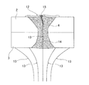
- FIG. 3 is a top view of the vicinity of the welded portion 4
- FIG. 4 is a cross-sectional view taken along the line AA of FIG.
- FIG. 4 shows a state in which a welding defect 14 in the welded portion 4 is detected by injecting air 13.
- the welded portion 4 in the present invention includes a molten portion corresponding to a portion where the base metal is melted at the time of welding, and a heat-affected zone (HAZ) in which the structure is changed by welding heat in the vicinity thereof.
- HZ heat-affected zone
- the welding defect 14 often propagates to the entire area from the welding start end portion S to the welding end portion E.
- the sealing liquid 12 is applied to the surface side of the welded portion 4.
- the liquid 12 may have a surface tension sufficient to seal the surface of the welded portion 4, and may cause a foaming phenomenon by injecting air.
- a liquid containing an effervescent factor such as a surfactant or a polymer compound can be used, such as a known gas leak detection liquid.
- the air 13 is injected from the back surface side of the metal plate 3 to the welded portion 4 coated with the liquid 12.
- a welding defect 14 specifically, a crack extending over the entire length of the welded portion in the plate thickness direction
- the air 13 passes through the welding defect 14 and is a metal plate. It reaches the surface side of 2.
- the air 13 generates bubbles 15 when passing through the liquid 12 on the surface side of the welded portion 4.
- the air 13 injected from the back surface side of the metal plate 3 is the surface of the metal plate 2. It does not reach the side and does not generate bubbles 15 in the liquid 12.
- the presence or absence of the welding defect 14 is determined by the presence or absence of bubbles 15 observed in the liquid 12 on the front side of the welded portion 4 when the air 13 is injected from the back surface side of the welded portion 4.
- the detection work can be performed online, the period required for the detection work can be significantly shortened as compared with the conventional case.
- the welding inspection device is applied to a welded portion of an alloyed thin steel plate, a welded portion formed by laser welding, or the like, even minute welding defects can be reliably detected.
- the welded portion 4 is cut out in a cross section perpendicular to the welding direction, and the cut surface is observed with an optical microscope or the like to determine the presence or absence of the welding defect 14. Can be certified more reliably.
- the various preferable conditions of the welding inspection device will be described below.
- the present invention is not limited to the following suitable conditions.
- the viscosity ⁇ of the liquid 12 is preferably 0.003 Pa ⁇ s or more and 1 Pa ⁇ s or less. More preferably, it is in the range of 0.005 Pa ⁇ s or more and 0.5 Pa ⁇ s or less.
- the amount a of the liquid 12 to be applied per unit surface area of the weld 4 is preferably set to 0.0001 / mm 2 or more 0.003 ml / mm 2 or less. More preferably, it is in the range of 0.0005 ml / mm 2 or more and 0.002 ml / mm 2 or less.
- the diameter ⁇ 1 of the liquid coating nozzle 6 is preferably 0.1 mm or more and 5.0 mm or less. More preferably, it is in the range of 0.5 mm or more and 3 mm or less.
- the distance d1 between the liquid coating nozzle 6 and the surface of the metal plate 2 is preferably 1.0 mm or more and 5.0 mm or less. More preferably, it is in the range of 1.5 mm or more and 4 mm or less.
- the feeding speed V of the liquid 12 is preferably 1.0 mm / s or more and 1000 mm / s or less. More preferably, it is in the range of 5.0 mm / s or more and 100 mm / s or less.
- the feed amount b of the air 13 is preferably 10 ml / min or more and 50 ml / min or less. More preferably, it is in the range of 15 ml / min or more and 40 ml / min or less.
- ⁇ Angle formed by the air injection nozzle 10 and the metal plate 3 on the back surface side ⁇ (deg)>
- the angle ⁇ is smaller than 30 °, it becomes difficult for the air 13 to pass through the welding defect 14, and the welding defect 14 may not be detected.
- the above-mentioned ⁇ is preferably 30 ° or more and 90 ° or less. More preferably, it is in the range of 45 ° or more and 90 ° or less.
- the direction in which the air injection nozzle 10 is tilted is not particularly limited.
- ⁇ Inner diameter of air injection nozzle 10 ⁇ 2 (mm)>
- ⁇ 2 0.1 mm or more and 5.0 mm or less. More preferably, it is in the range of 1.0 mm or more and 4.0 mm or less.
- d2 (mm)>
- d2 is preferably 1.0 mm or more and 5.0 mm or less. More preferably, it is in the range of 1.5 mm or more and 4.0 mm or less.
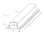
- An example of an inspection object to which the welding inspection apparatus according to the present invention can be applied is a skeleton part for an automobile.
- a specific example of a skeleton component for an automobile is shown in FIG. In FIG. 5, a steel plate 2 which is a frame component having a substantially hat-shaped cross section and a steel plate 3 which is a panel component are used.
- the skeleton component for an automobile has a closed cross section formed by welding a flange portion 2b of a frame component (steel plate 2) and a part of a panel component (steel plate 3) facing the flange portion 2b.
- the above-mentioned automobile frame parts include center pillars, roof rails, and the like.
- a thin steel plate made of a high-strength steel plate is generally used for these members, and laser welding is often used for lap welding of the flange portion, so that there is a high possibility that minute welding defects will occur.
- the minute welding defect can be detected easily and accurately.
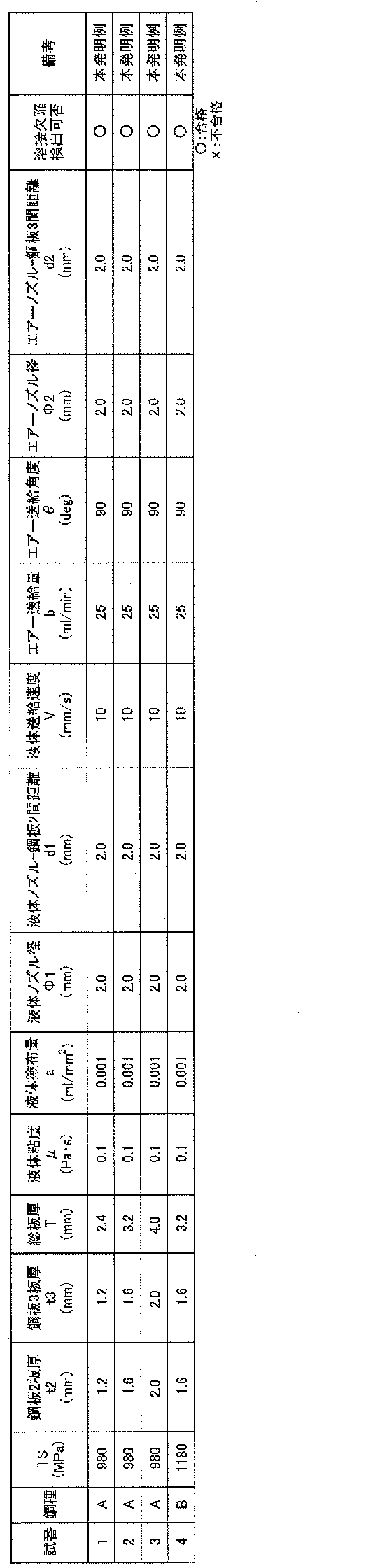
- a steel sheet having the composition shown in Table 1 was used as the test material. More specifically, two steel sheets having a component composition of either steel type A or B were overwelded.
- the plate thickness of the steel material was one of 1, 2 mm, 1.6 mm, and 2.0 mm for the steel type A, and 1.6 mm for the steel type B.
- the steel plate 2 and the steel plate 3 at the time of lap welding had the same plate thickness.
- the lengths of the steel plates 2 and 3 in the longitudinal direction were all 500 mm.
- the steel plate 2 is a hat type having a vertical wall portion 2a and a flange portion 2b, and the steel plate 2 and the steel plate 3 are overlap-welded in the same manner as in FIG.
- the welding defect was determined by the following procedure. (1) Does the liquid 12 generate bubbles 15 after the liquid 12 is applied from the front surface side to the 20 welded portions 4 formed on the flange portion of the hat type test piece and the air 13 is injected from the back surface side? I confirmed. (2) For each of the 20 welded portions 4, a portion 5 mm away from the welded end portion E was cut out perpendicular to the welding direction, and cross-sectional observation was performed. (3) Pass if the welded part where air bubbles are generated in the liquid 12 on the surface in (1) and the welded part where the welding defect 14 is found in (2) match in all 20 places, and even one matches. If not, it was rejected. The results obtained are shown in Table 2.
- No. 1 of the example of the present invention. 1 to No. In any of the cases 4, the above-mentioned preferable conditions were satisfied, and welding defects could be detected more accurately. That is, No. 1 to No.
- the liquid viscosity ⁇ of No. 4 is 0.1 Pa ⁇ s, and satisfies the condition of 0.003 Pa ⁇ s or more and 1 Pa ⁇ s or less. As a result, the air 13 could pass through the liquid 12 of the hat-shaped metal plate 2, and the liquid 12 applied to the surface of the welded portion 4 could be foamed.
- the coating amount of the liquid 12 in 4 a is 0.001 ml / mm 2, meets 0.0001 / mm 2 or more 0.003 ml / mm 2 following conditions. Therefore, the liquid 12 was applied to the entire welded portion 4, and the surface of the welded portion 4 could be completely sealed.
- the ⁇ 1 of the liquid nozzle 6 of No. 4 is 2.0 mm, which satisfies the condition of 0.1 mm or more and 5.0 mm or less. Therefore, the liquid nozzle 6 was not clogged, and the liquid 12 could be reliably prevented from flowing to the outside of the welded portion 4.
- the distance d1 between the liquid nozzle 6 and the metal plate 2 of No. 4 is 2.0 mm, which satisfies the condition of 1.0 mm or more and 5.0 mm or less.
- the liquids 12 having different supply timings do not interfere with each other, and it is possible to prevent a portion where the liquid 12 is not applied to the welded portion 4.
- the feeding speed V of the liquid 12 of No. 4 is 10 mm / s, and satisfies the condition of 1.0 mm / s or more and 1000 mm / s or less. Therefore, the liquid 12 could be sealed to the welded portion 4 while shortening the coating time.
- the feed amount b of the air 13 of 4 is 25 ml / min, which satisfies the condition of 10 ml / min or more and 50 ml / min or less, and the feed angle ⁇ of the air 13 is 90 °, and the condition of 30 ° or more and 90 ° or less. Meet. As a result, the air 13 could be reliably passed through the welding defect 14 and the bubbles 15 could be generated.
- the diameter ⁇ 2 of the air injection nozzle 10 of No. 4 is 2.0 mm, which satisfies the condition of 0.1 mm or more and 5.0 mm or less.
- the distance d2 between the air injection nozzle 10 of 4 and the metal plate 3 is 2.0 mm, which satisfies the condition of 1.0 mm or more and 5.0 mm or less. Therefore, the pressure of the injected air 13 could be secured and the bubbles 15 could be generated without the air 13 coming off from the welding defect 14.
- Example No. 1 of the present invention satisfying all of the suitable conditions. 1 to No. In No. 4, an accurate determination result of the presence or absence of the welding defect 14 was obtained.
- the embodiment of the present invention is not limited to the above embodiment, and various modifications can be made.
- the inspection of the welded portion when the metal plate is a steel material such as high-strength steel is illustrated, but the present invention is not limited to this, and mild steel, plated steel plate, stainless steel, heat-resistant steel, aluminum alloy, etc. It can also be applied to the inspection of the welded part of the metal plate of.
- the welding method is not limited to the laser welding described above, and a known welding method suitable for the type of metal plate can be applied.
- the welding inspection device 1 inspects the lap welding is illustrated, it can also be applied to the butt welding.
Landscapes
- Engineering & Computer Science (AREA)
- Physics & Mathematics (AREA)
- Chemical & Material Sciences (AREA)
- Health & Medical Sciences (AREA)
- Life Sciences & Earth Sciences (AREA)
- Mechanical Engineering (AREA)
- Optics & Photonics (AREA)
- Immunology (AREA)
- Biochemistry (AREA)
- General Health & Medical Sciences (AREA)
- General Physics & Mathematics (AREA)
- Analytical Chemistry (AREA)
- Pathology (AREA)
- Quality & Reliability (AREA)
- Plasma & Fusion (AREA)
- Signal Processing (AREA)
- Medicinal Chemistry (AREA)
- Food Science & Technology (AREA)
- Computer Vision & Pattern Recognition (AREA)
- Textile Engineering (AREA)
- Multimedia (AREA)
- Investigating Materials By The Use Of Optical Means Adapted For Particular Applications (AREA)
- Laser Beam Processing (AREA)
- Crystallography & Structural Chemistry (AREA)
Abstract
Description
[1] 金属板の溶接部における溶接欠陥を検出する溶接検査装置であって、
金属板の一方面側に配置されて金属板の溶接方向に進行可能な液体塗布ヘッドと、
金属板の他方面側に配置されて金属板の溶接方向に進行可能なエアー噴射ヘッドと、を有し、
前記液体塗布ヘッドは、金属板の一方面側へ突出し、溶接部をシールする液体を塗布する液体塗布ノズルを有し、
前記エアー噴射ヘッドは、金属板の他方面側へ突出し、液体を塗布された溶接部にエアーを噴射するエアー噴射ノズルを有する溶接検査装置。
[2] 前記液体塗布ヘッドは、前記液体塗布ノズルよりも進行方向の前方に、溶接部を撮影するカメラを有する[1]に記載の溶接検査装置。
[3] 前記エアー噴射ヘッドは、前記エアー噴射ノズルよりも進行方向の前方に、溶接部を撮影するカメラを有する[1]又は[2]に記載の溶接検査装置。
[4] 前記液体塗布ノズルは、前記エアー噴射ノズルよりも進行方向の前方に、配置される[1]から[3]までのいずれかに記載の溶接検査装置。
[5] 前記液体塗布ヘッドは、前記液体塗布ノズルよりも進行方向の後方に、液体中で発生する泡を撮影する後方カメラを有する[1]から[4]までのいずれかに記載の溶接検査装置。
また、液体塗布ヘッド及びエアー噴射ヘッドが溶接方向へ進行することにより、オンラインでの検出が可能となるので、オフラインで行う検出装置及び検出方法に比べて、検査時間を大幅に短縮できる。
図1に示すように、本発明に係る溶接検査装置1は、液体塗布ヘッド5とエアー噴射ヘッド9とを有する。液体塗布ヘッド5は、金属板の一方面側(表面側)へ突出する筒状の液体塗布ノズル6を有する。エアー噴射ヘッド9は、金属板の他方面側(裏面側)へ突出する筒状のエアー噴射ノズル10を有する。図2のように、液体塗布ノズル6によって金属板2の表面に液体12が塗布され、エアー噴射ノズル10によって金属板3の裏面からエアー13が噴射される。
液体12の粘度が大きい場合、エアー13が液体12によりブロックされ、溶接欠陥14を通過できないことがある。一方で、液体12の粘度が小さい場合、貫通した溶接欠陥14がある金属板2、3に対して噴射されたエアー13が、溶接部4の表面に塗布した液体12を泡立てることなく、液体12を通過することがある。これらの観点から、液体12の粘度μは、0.003Pa・s以上1Pa・s以下とすることが好ましい。さらに好ましくは0.005Pa・s以上0.5Pa・s以下の範囲である。
液体12の塗布量が少ない場合、溶接部4の表面全体に液体12が広がらず、溶接部4の表面を完全にシールすることができないことがある。この場合、エアー13が液体12の塗布されていない部分を通過することで、泡15が発生せず溶接欠陥14を検出できないという問題が起こりうる。一方で、液体12の塗布量が多い場合、液体12が溶接部4から流出して溶接部4の表面をシールできなくなる可能性がある。これらの観点から、溶接部4の単位表面積あたりに塗布する液体12の量aは、0.0001ml/mm2以上0.003ml/mm2以下とすることが好ましい。さらに好ましくは0.0005ml/mm2以上0.002ml/mm2以下の範囲である。
液体塗布ノズル6の直径が小さい場合、ノズルの先端が目詰まりを起こす可能性がある。一方で、液体塗布ノズル6の直径が大きい場合、ノズルの内径が溶接部4の幅より大きくなり、液体12が溶接部4の外側に流出する可能性がある。これらの観点から、液体塗布ノズル6の直径Φ1は、0.1mm以上5.0mm以下とすることが好ましい。さらに好ましくは0.5mm以上~3mm以下の範囲である。
上記距離d1が小さい場合、金属板2に接触した液体12と後から供給される液体12とが干渉し、液体塗布ノズル6から適切に液体12を供給できない可能性がある。一方、上記距離d1が大きい場合、目的の箇所に液体12を塗布することができない可能性がある。これらの観点から、液体塗布ノズル6と金属板2の表面との間の距離d1は、1.0mm以上5.0mm以下とすることが好ましい。さらに好ましくは1.5mm以上~4mm以下の範囲である。
液体12の送給速度が小さい場合、液体12の塗布作業に要する時間が過大となる。一方で、液体12の送給速度が大きい場合、液体12が溶接部4の表面から飛び散り、上手く表面をシールできない可能性がある。これらの観点から、液体12の送給速度Vは、1.0mm/s以上1000mm/s以下とすることが好ましい。さらに好ましくは5.0mm/s以上100mm/s以下の範囲である。
エアー13の送給量が少ない場合、板厚方向に貫通する溶接欠陥14が存在する場合でも、エアー13が当該溶接欠陥14を通過しない可能性がある。一方でエアー13の送給量が多い場合、エアー13が金属板表面の液体12を吹き飛ばしてしまい、溶接欠陥14が検出できない可能性がある。これらの観点から、エアー13の送給量bは、10ml/min以上50ml/min以下とすることが好ましい。さらに好ましくは15ml/min以上40ml/min以下の範囲である。
角度θが30°よりも小さい場合、エアー13が溶接欠陥14を通過しにくくなり、溶接欠陥14を検出できない可能性がある。一方で、エアー13の溶接欠陥14における通過しやすさを考えると、θは90°に近い方が望ましい。よって、上述のθは30°以上90°以下とすることが好ましい。さらに好ましくは45°以上90°以下の範囲である。尚、上述のθを算出する際に、エアー噴射ノズル10が傾斜する方向は特に限定されない。
内径Φ2が小さい場合、エアー13が溶接欠陥14から外れた位置に噴射された際に、溶接欠陥14を検出することが難しい。一方で、上述のΦ2が大きい場合、噴射するエアー13の圧力を確保できず、エアー13が板厚方向に貫通した溶接欠陥14を通過することができず、溶接欠陥14を検出することが難しいことがある。以上の観点から、Φ2は0.1mm以上5.0mm以下とすることが望ましい。さらに望ましくは1.0mm以上4.0mm以下の範囲である。
距離d2が小さい場合、エアー13が溶接欠陥14から外れた位置に噴射された際に、溶接欠陥14を検出することが難しい。一方で上述のd2が大きい場合、エアー13が金属板3の裏面に到達するまでに広がってしまい、圧力を確保できず、溶接欠陥14を検出することが難しいことがある。以上の観点から、d2は1.0mm以上5.0mm以下とすることが好ましい。さらに好ましくは1.5mm以上4.0mm以下の範囲である。
本発明に係る溶接検査装置を適用可能な検査対象物の一例として、自動車用骨格部品が挙げられる。自動車用骨格部品の具体例を図5に示す。図5では、断面形状が略ハット形状のフレーム部品である鋼板2と、パネル部品である鋼板3とが用いられる。当該自動車用骨格部品は、フレーム部品(鋼板2)のフランジ部2bと、当該フランジ部2bに対向するパネル部品(鋼板3)の一部とが溶接されて、閉断面を構成する。
(1)ハット型試験片のフランジ部に形成された20箇所の溶接部4に、表面側から液体12を塗布し、裏面側からエアー13を噴射した後に、液体12に泡15が発生するかどうかを確認した。
(2)20箇所の溶接部4のそれぞれについて、溶接終端部Eから5mm離れた箇所を溶接方向と垂直に切り出し、断面観察を実施した。
(3)(1)で表面の液体12に気泡が発生した溶接個所と、(2)で溶接欠陥14がみられた溶接個所が20箇所全てで一致していれば合格、一つでも一致していない場合には不合格とした。得られた結果を表2に示す。

2、3 金属板(鋼板)
2a 縦壁部
2b フランジ部
4 溶接部
5 液体塗布ヘッド
6 液体塗布ノズル
7 カメラ
8 後方カメラ
9 エアー噴射ヘッド
10 エアー噴射ノズル
11 カメラ
12 液体
13 エアー
14 溶接欠陥
D 進行方向
E 溶接終端部
S 溶接始端部
Claims (5)
- 金属板の溶接部における溶接欠陥を検出する溶接検査装置であって、
金属板の一方面側に配置されて金属板の溶接方向に進行可能な液体塗布ヘッドと、
金属板の他方面側に配置されて金属板の溶接方向に進行可能なエアー噴射ヘッドと、を有し、
前記液体塗布ヘッドは、金属板の一方面側へ突出し、溶接部をシールする液体を塗布する液体塗布ノズルを有し、
前記エアー噴射ヘッドは、金属板の他方面側へ突出し、液体を塗布された溶接部にエアーを噴射するエアー噴射ノズルを有する溶接検査装置。 - 前記液体塗布ヘッドは、前記液体塗布ノズルよりも進行方向の前方に、溶接部を撮影するカメラを有する請求項1に記載の溶接検査装置。
- 前記エアー噴射ヘッドは、前記エアー噴射ノズルよりも進行方向の前方に、溶接部を撮影するカメラを有する請求項1又は2に記載の溶接検査装置。
- 前記液体塗布ノズルは、前記エアー噴射ノズルよりも進行方向の前方に、配置される請求項1から3までのいずれか一項に記載の溶接検査装置。
- 前記液体塗布ヘッドは、前記液体塗布ノズルよりも進行方向の後方に、液体中で発生する泡を撮影する後方カメラを有する請求項1から4までのいずれか一項に記載の溶接検査装置。
Priority Applications (6)
| Application Number | Priority Date | Filing Date | Title |
|---|---|---|---|
| KR1020227017103A KR20220084393A (ko) | 2019-11-27 | 2020-10-14 | 용접 검사 장치 |
| EP20893061.0A EP4029642A4 (en) | 2019-11-27 | 2020-10-14 | WELD INSPECTION DEVICE |
| MX2022006120A MX2022006120A (es) | 2019-11-27 | 2020-10-14 | Aparato de inspeccion de soldadura. |
| CN202080080883.5A CN114728381B (zh) | 2019-11-27 | 2020-10-14 | 焊接检查装置 |
| US17/778,583 US20230001519A1 (en) | 2019-11-27 | 2020-10-14 | Weld inspection apparatus |
| JP2021507714A JP7243812B2 (ja) | 2019-11-27 | 2020-10-14 | 溶接検査装置 |
Applications Claiming Priority (2)
| Application Number | Priority Date | Filing Date | Title |
|---|---|---|---|
| JP2019213856 | 2019-11-27 | ||
| JP2019-213856 | 2019-11-27 |
Publications (1)
| Publication Number | Publication Date |
|---|---|
| WO2021106400A1 true WO2021106400A1 (ja) | 2021-06-03 |
Family
ID=76129302
Family Applications (1)
| Application Number | Title | Priority Date | Filing Date |
|---|---|---|---|
| PCT/JP2020/038690 WO2021106400A1 (ja) | 2019-11-27 | 2020-10-14 | 溶接検査装置 |
Country Status (7)
| Country | Link |
|---|---|
| US (1) | US20230001519A1 (ja) |
| EP (1) | EP4029642A4 (ja) |
| JP (1) | JP7243812B2 (ja) |
| KR (1) | KR20220084393A (ja) |
| CN (1) | CN114728381B (ja) |
| MX (1) | MX2022006120A (ja) |
| WO (1) | WO2021106400A1 (ja) |
Cited By (1)
| Publication number | Priority date | Publication date | Assignee | Title |
|---|---|---|---|---|
| CN115077806A (zh) * | 2022-08-22 | 2022-09-20 | 山东福尔特种设备有限公司 | 一种压力容器焊缝无损快速检测装置 |
Citations (7)
| Publication number | Priority date | Publication date | Assignee | Title |
|---|---|---|---|---|
| JPS603535A (ja) * | 1983-06-20 | 1985-01-09 | Kawasaki Steel Corp | 動圧気体による漏洩試験方法 |
| JP2000180384A (ja) * | 1998-12-15 | 2000-06-30 | Jgc Corp | 非破壊検査システムおよび非破壊検査方法 |
| JP2002139398A (ja) * | 2000-10-30 | 2002-05-17 | Nikki Plantec Kk | 配管気密検査装置 |
| JP2006167676A (ja) * | 2004-12-20 | 2006-06-29 | Nissan Motor Co Ltd | ブレージング接合部のシーリング材塗布方法および塗布装置 |
| JP2008196866A (ja) | 2007-02-08 | 2008-08-28 | Toyota Motor Corp | 溶接割れ検出方法および装置 |
| JP2008279497A (ja) | 2007-05-14 | 2008-11-20 | Toyota Motor Corp | 溶接割れ検出方法 |
| JP2013034999A (ja) * | 2011-08-04 | 2013-02-21 | Daido Steel Co Ltd | 管内面溶接補修装置 |
Family Cites Families (8)
| Publication number | Priority date | Publication date | Assignee | Title |
|---|---|---|---|---|
| JP2001066213A (ja) * | 1999-08-26 | 2001-03-16 | Taisei Corp | タンク内気密検査方法 |
| JP6239230B2 (ja) * | 2012-12-05 | 2017-11-29 | 三菱日立パワーシステムズ株式会社 | タービンロータの製造方法 |
| JP3182190U (ja) * | 2012-12-17 | 2013-03-14 | 有限会社田中鉄工 | 溶接部の欠陥部検出装置 |
| JP3194227U (ja) * | 2014-07-23 | 2014-11-13 | 有限会社田中鉄工 | T型当接部の溶接欠陥検出構造 |
| EP3352578B1 (en) * | 2015-09-22 | 2021-09-01 | Sanuwave, Inc. | Cleaning and grooming water submerged structures using acoustic pressure shock waves |
| US10682729B2 (en) * | 2015-12-01 | 2020-06-16 | General Electric Company | System for automated in-process inspection of welds |
| US10035311B1 (en) * | 2017-01-09 | 2018-07-31 | GM Global Technology Operations LLC | Method for manufacturing a leak tight porous component |
| US20220196569A1 (en) * | 2019-04-24 | 2022-06-23 | Nikon Corporation | Processing system and inspection system |
-
2020
- 2020-10-14 US US17/778,583 patent/US20230001519A1/en active Pending
- 2020-10-14 CN CN202080080883.5A patent/CN114728381B/zh active Active
- 2020-10-14 EP EP20893061.0A patent/EP4029642A4/en active Pending
- 2020-10-14 MX MX2022006120A patent/MX2022006120A/es unknown
- 2020-10-14 JP JP2021507714A patent/JP7243812B2/ja active Active
- 2020-10-14 WO PCT/JP2020/038690 patent/WO2021106400A1/ja unknown
- 2020-10-14 KR KR1020227017103A patent/KR20220084393A/ko not_active Application Discontinuation
Patent Citations (7)
| Publication number | Priority date | Publication date | Assignee | Title |
|---|---|---|---|---|
| JPS603535A (ja) * | 1983-06-20 | 1985-01-09 | Kawasaki Steel Corp | 動圧気体による漏洩試験方法 |
| JP2000180384A (ja) * | 1998-12-15 | 2000-06-30 | Jgc Corp | 非破壊検査システムおよび非破壊検査方法 |
| JP2002139398A (ja) * | 2000-10-30 | 2002-05-17 | Nikki Plantec Kk | 配管気密検査装置 |
| JP2006167676A (ja) * | 2004-12-20 | 2006-06-29 | Nissan Motor Co Ltd | ブレージング接合部のシーリング材塗布方法および塗布装置 |
| JP2008196866A (ja) | 2007-02-08 | 2008-08-28 | Toyota Motor Corp | 溶接割れ検出方法および装置 |
| JP2008279497A (ja) | 2007-05-14 | 2008-11-20 | Toyota Motor Corp | 溶接割れ検出方法 |
| JP2013034999A (ja) * | 2011-08-04 | 2013-02-21 | Daido Steel Co Ltd | 管内面溶接補修装置 |
Cited By (2)
| Publication number | Priority date | Publication date | Assignee | Title |
|---|---|---|---|---|
| CN115077806A (zh) * | 2022-08-22 | 2022-09-20 | 山东福尔特种设备有限公司 | 一种压力容器焊缝无损快速检测装置 |
| CN115077806B (zh) * | 2022-08-22 | 2022-11-08 | 山东福尔特种设备有限公司 | 一种压力容器焊缝无损快速检测装置 |
Also Published As
| Publication number | Publication date |
|---|---|
| CN114728381B (zh) | 2023-12-19 |
| JPWO2021106400A1 (ja) | 2021-12-02 |
| CN114728381A (zh) | 2022-07-08 |
| EP4029642A1 (en) | 2022-07-20 |
| US20230001519A1 (en) | 2023-01-05 |
| EP4029642A4 (en) | 2022-12-14 |
| JP7243812B2 (ja) | 2023-03-22 |
| KR20220084393A (ko) | 2022-06-21 |
| MX2022006120A (es) | 2022-06-14 |
Similar Documents
| Publication | Publication Date | Title |
|---|---|---|
| US8322008B2 (en) | Method of repairing a metallic artifact | |
| Dialami et al. | Prediction of joint line remnant defect in friction stir welding | |
| WO2021106400A1 (ja) | 溶接検査装置 | |
| CN106001912B (zh) | 一种焊接设备 | |
| CN110961821A (zh) | 一种实现带钢激光拼接焊缝检查自动判定与放行的方法 | |
| JP6278852B2 (ja) | 金属キャスク用伝熱銅フィンの溶接方法及び伝熱銅フィン付き金属キャスク | |
| US6450392B1 (en) | Groove shape for single butt welding and inspection method of weld zone thereof | |
| JP4396352B2 (ja) | 溶接状態の検査方法と検査装置 | |
| Bakir et al. | Novel metrology to determine the critical strain conditions required for solidification cracking during laser welding of thin sheets | |
| Tarasov et al. | Radiographic detection of defects in friction stir welding on aluminum alloy AMg5M | |
| JP2001047232A (ja) | 片面突合せ溶接用開先形状及びその溶接部の検査方法 | |
| JP2007196266A (ja) | 両面溶接方法及びその溶接構造物 | |
| Kam et al. | Porosity reduction through a Ti particle based gap-paste in arc welding of zinc coated steel | |
| Wang et al. | In situ monitoring of internal defects by a laser sensor for CMT based wire-arc additive manufacturing parts | |
| Braun et al. | Camera-based laser beam welding sensor in the near infrared spectral range | |
| US7847208B2 (en) | Methods for performing manual laser deposition | |
| JP2008178894A (ja) | 両面溶接方法 | |
| Dhanya et al. | Metallurgical investigation of leakage observed in welded interface of Pilot pressure distributor of liquid stage for aerospace application | |
| JP2003019584A (ja) | レーザ溶接方法 | |
| RU2336981C2 (ru) | Способ дуговой сварки в защитных газах стыкового соединения монолитной заготовки с двухслойным пакетом из алюминиевых сплавов | |
| Vänskä et al. | Investigation of the keyhole in laser welding of different joint geometries by means of x-ray videography | |
| Bourlet et al. | In Situ Monitoring of Internal Defects by a Laser Sensor for CMT Based Wire-Arc Additive Manufacturing Parts | |
| JP2023150976A (ja) | 異種金属接合継手の検査方法、異種金属接合継手の製造方法及び異種金属接合継手 | |
| Khodabandeh et al. | Ali Mehrani Milani, Moslem Paidar | |
| JPH11320150A (ja) | レーザ溶接方法 |
Legal Events
| Date | Code | Title | Description |
|---|---|---|---|
| ENP | Entry into the national phase |
Ref document number: 2021507714 Country of ref document: JP Kind code of ref document: A |
|
| 121 | Ep: the epo has been informed by wipo that ep was designated in this application |
Ref document number: 20893061 Country of ref document: EP Kind code of ref document: A1 |
|
| ENP | Entry into the national phase |
Ref document number: 2020893061 Country of ref document: EP Effective date: 20220413 |
|
| ENP | Entry into the national phase |
Ref document number: 20227017103 Country of ref document: KR Kind code of ref document: A |
|
| NENP | Non-entry into the national phase |
Ref country code: DE |