WO2021095487A1 - コネクタ装置 - Google Patents
コネクタ装置 Download PDFInfo
- Publication number
- WO2021095487A1 WO2021095487A1 PCT/JP2020/039871 JP2020039871W WO2021095487A1 WO 2021095487 A1 WO2021095487 A1 WO 2021095487A1 JP 2020039871 W JP2020039871 W JP 2020039871W WO 2021095487 A1 WO2021095487 A1 WO 2021095487A1
- Authority
- WO
- WIPO (PCT)
- Prior art keywords
- terminal
- adapter
- connector
- movable
- outer conductor
- Prior art date
- Legal status (The legal status is an assumption and is not a legal conclusion. Google has not performed a legal analysis and makes no representation as to the accuracy of the status listed.)
- Ceased
Links
Images


Classifications
-
- H—ELECTRICITY
- H01—ELECTRIC ELEMENTS
- H01R—ELECTRICALLY-CONDUCTIVE CONNECTIONS; STRUCTURAL ASSOCIATIONS OF A PLURALITY OF MUTUALLY-INSULATED ELECTRICAL CONNECTING ELEMENTS; COUPLING DEVICES; CURRENT COLLECTORS
- H01R13/00—Details of coupling devices of the kinds covered by groups H01R12/70 or H01R24/00 - H01R33/00
- H01R13/02—Contact members
-
- H—ELECTRICITY
- H01—ELECTRIC ELEMENTS
- H01R—ELECTRICALLY-CONDUCTIVE CONNECTIONS; STRUCTURAL ASSOCIATIONS OF A PLURALITY OF MUTUALLY-INSULATED ELECTRICAL CONNECTING ELEMENTS; COUPLING DEVICES; CURRENT COLLECTORS
- H01R24/00—Two-part coupling devices, or either of their cooperating parts, characterised by their overall structure
- H01R24/38—Two-part coupling devices, or either of their cooperating parts, characterised by their overall structure having concentrically or coaxially arranged contacts
- H01R24/40—Two-part coupling devices, or either of their cooperating parts, characterised by their overall structure having concentrically or coaxially arranged contacts specially adapted for high frequency
- H01R24/54—Intermediate parts, e.g. adapters, splitters or elbows
- H01R24/542—Adapters
-
- H—ELECTRICITY
- H01—ELECTRIC ELEMENTS
- H01R—ELECTRICALLY-CONDUCTIVE CONNECTIONS; STRUCTURAL ASSOCIATIONS OF A PLURALITY OF MUTUALLY-INSULATED ELECTRICAL CONNECTING ELEMENTS; COUPLING DEVICES; CURRENT COLLECTORS
- H01R12/00—Structural associations of a plurality of mutually-insulated electrical connecting elements, specially adapted for printed circuits, e.g. printed circuit boards [PCB], flat or ribbon cables, or like generally planar structures, e.g. terminal strips, terminal blocks; Coupling devices specially adapted for printed circuits, flat or ribbon cables, or like generally planar structures; Terminals specially adapted for contact with, or insertion into, printed circuits, flat or ribbon cables, or like generally planar structures
- H01R12/70—Coupling devices
- H01R12/91—Coupling devices allowing relative movement between coupling parts, e.g. floating or self aligning
-
- H—ELECTRICITY
- H01—ELECTRIC ELEMENTS
- H01R—ELECTRICALLY-CONDUCTIVE CONNECTIONS; STRUCTURAL ASSOCIATIONS OF A PLURALITY OF MUTUALLY-INSULATED ELECTRICAL CONNECTING ELEMENTS; COUPLING DEVICES; CURRENT COLLECTORS
- H01R12/00—Structural associations of a plurality of mutually-insulated electrical connecting elements, specially adapted for printed circuits, e.g. printed circuit boards [PCB], flat or ribbon cables, or like generally planar structures, e.g. terminal strips, terminal blocks; Coupling devices specially adapted for printed circuits, flat or ribbon cables, or like generally planar structures; Terminals specially adapted for contact with, or insertion into, printed circuits, flat or ribbon cables, or like generally planar structures
- H01R12/70—Coupling devices
- H01R12/71—Coupling devices for rigid printing circuits or like structures
-
- H—ELECTRICITY
- H01—ELECTRIC ELEMENTS
- H01R—ELECTRICALLY-CONDUCTIVE CONNECTIONS; STRUCTURAL ASSOCIATIONS OF A PLURALITY OF MUTUALLY-INSULATED ELECTRICAL CONNECTING ELEMENTS; COUPLING DEVICES; CURRENT COLLECTORS
- H01R13/00—Details of coupling devices of the kinds covered by groups H01R12/70 or H01R24/00 - H01R33/00
- H01R13/02—Contact members
- H01R13/10—Sockets for co-operation with pins or blades
-
- H—ELECTRICITY
- H01—ELECTRIC ELEMENTS
- H01R—ELECTRICALLY-CONDUCTIVE CONNECTIONS; STRUCTURAL ASSOCIATIONS OF A PLURALITY OF MUTUALLY-INSULATED ELECTRICAL CONNECTING ELEMENTS; COUPLING DEVICES; CURRENT COLLECTORS
- H01R13/00—Details of coupling devices of the kinds covered by groups H01R12/70 or H01R24/00 - H01R33/00
- H01R13/40—Securing contact members in or to a base or case; Insulating of contact members
- H01R13/42—Securing in a demountable manner
-
- H—ELECTRICITY
- H01—ELECTRIC ELEMENTS
- H01R—ELECTRICALLY-CONDUCTIVE CONNECTIONS; STRUCTURAL ASSOCIATIONS OF A PLURALITY OF MUTUALLY-INSULATED ELECTRICAL CONNECTING ELEMENTS; COUPLING DEVICES; CURRENT COLLECTORS
- H01R24/00—Two-part coupling devices, or either of their cooperating parts, characterised by their overall structure
- H01R24/38—Two-part coupling devices, or either of their cooperating parts, characterised by their overall structure having concentrically or coaxially arranged contacts
- H01R24/40—Two-part coupling devices, or either of their cooperating parts, characterised by their overall structure having concentrically or coaxially arranged contacts specially adapted for high frequency
- H01R24/50—Two-part coupling devices, or either of their cooperating parts, characterised by their overall structure having concentrically or coaxially arranged contacts specially adapted for high frequency mounted on a PCB [Printed Circuit Board]
-
- H—ELECTRICITY
- H01—ELECTRIC ELEMENTS
- H01R—ELECTRICALLY-CONDUCTIVE CONNECTIONS; STRUCTURAL ASSOCIATIONS OF A PLURALITY OF MUTUALLY-INSULATED ELECTRICAL CONNECTING ELEMENTS; COUPLING DEVICES; CURRENT COLLECTORS
- H01R24/00—Two-part coupling devices, or either of their cooperating parts, characterised by their overall structure
- H01R24/38—Two-part coupling devices, or either of their cooperating parts, characterised by their overall structure having concentrically or coaxially arranged contacts
- H01R24/40—Two-part coupling devices, or either of their cooperating parts, characterised by their overall structure having concentrically or coaxially arranged contacts specially adapted for high frequency
- H01R24/54—Intermediate parts, e.g. adapters, splitters or elbows
-
- H—ELECTRICITY
- H01—ELECTRIC ELEMENTS
- H01R—ELECTRICALLY-CONDUCTIVE CONNECTIONS; STRUCTURAL ASSOCIATIONS OF A PLURALITY OF MUTUALLY-INSULATED ELECTRICAL CONNECTING ELEMENTS; COUPLING DEVICES; CURRENT COLLECTORS
- H01R12/00—Structural associations of a plurality of mutually-insulated electrical connecting elements, specially adapted for printed circuits, e.g. printed circuit boards [PCB], flat or ribbon cables, or like generally planar structures, e.g. terminal strips, terminal blocks; Coupling devices specially adapted for printed circuits, flat or ribbon cables, or like generally planar structures; Terminals specially adapted for contact with, or insertion into, printed circuits, flat or ribbon cables, or like generally planar structures
- H01R12/70—Coupling devices
- H01R12/7082—Coupling device supported only by cooperation with PCB
-
- H—ELECTRICITY
- H01—ELECTRIC ELEMENTS
- H01R—ELECTRICALLY-CONDUCTIVE CONNECTIONS; STRUCTURAL ASSOCIATIONS OF A PLURALITY OF MUTUALLY-INSULATED ELECTRICAL CONNECTING ELEMENTS; COUPLING DEVICES; CURRENT COLLECTORS
- H01R12/00—Structural associations of a plurality of mutually-insulated electrical connecting elements, specially adapted for printed circuits, e.g. printed circuit boards [PCB], flat or ribbon cables, or like generally planar structures, e.g. terminal strips, terminal blocks; Coupling devices specially adapted for printed circuits, flat or ribbon cables, or like generally planar structures; Terminals specially adapted for contact with, or insertion into, printed circuits, flat or ribbon cables, or like generally planar structures
- H01R12/70—Coupling devices
- H01R12/71—Coupling devices for rigid printing circuits or like structures
- H01R12/72—Coupling devices for rigid printing circuits or like structures coupling with the edge of the rigid printed circuits or like structures
- H01R12/73—Coupling devices for rigid printing circuits or like structures coupling with the edge of the rigid printed circuits or like structures connecting to other rigid printed circuits or like structures
-
- H—ELECTRICITY
- H01—ELECTRIC ELEMENTS
- H01R—ELECTRICALLY-CONDUCTIVE CONNECTIONS; STRUCTURAL ASSOCIATIONS OF A PLURALITY OF MUTUALLY-INSULATED ELECTRICAL CONNECTING ELEMENTS; COUPLING DEVICES; CURRENT COLLECTORS
- H01R2103/00—Two poles
Definitions
- This disclosure relates to a connector device.
- Patent Document 1 discloses a connector device having a first connector and a second connector facing each other and connecting both connectors via an adapter.
- the adapter is attached so that it can swing relative to the first connector.
- the adapter is tilted to absorb the misalignment of both connectors, so that both connectors can be connected.
- the first connector can be fixed to the ceiling of the vehicle body, and the adapter and the second connector can be assembled from the vehicle interior side.
- the adapter is attached to the first connector, the adapter is hung vertically downward from the first connector by its own weight, so that the work of assembling the second connector to the lower end of the adapter becomes easy.
- the adapter is simply fitted to the first connector, there is a concern that the adapter may fall due to its own weight. Therefore, the operator needs to support the adapter by hand so as not to drop it until the second connector is attached.
- the connector of the present disclosure has been completed based on the above circumstances, and an object thereof is to improve workability at the time of assembly.
- the connector device of the present disclosure is A pair of connectors that have terminals and are individually mounted on a pair of opposing circuit boards. It is provided with an adapter having a pair of connection ends that can be swingably connected to the terminal portion. A hook portion protruding in the radial direction from the connection end portion is formed at the connection end portion. The terminal portion is formed with a receiving portion that holds the adapter to the connector by locking the hook portion.
- the connector device of the present disclosure has good workability at the time of assembly.
- FIG. 1 is a perspective view of the first connector.
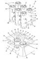
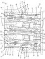
- FIG. 2 is a perspective view showing a state in which the adapter is separated in the second connector.
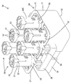
- FIG. 3 is a perspective view of the alignment member.
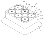
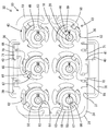
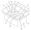
- FIG. 4 is a perspective view of the second connector.
- FIG. 5 is a side sectional view of the second connector.
- FIG. 6 is a plan view of the second connector with the alignment member removed.
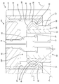
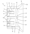
- FIG. 7 is a normal cross-sectional view in a state where the first connector and the second connector are fitted.
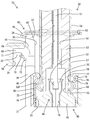
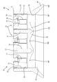
- FIG. 8 is a partially enlarged side sectional view showing a state in which the second connector is arranged on the upper side and the adapter is suspended and held by the second connector.
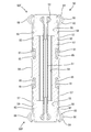
- FIG. 9 is a front sectional view of the adapter.
- FIG. 10 is a partially enlarged plan view showing a state in which the adapter and the hole portion of the alignment member are arranged coaxially.
- FIG. 11 is a perspective view showing a state in which the first connector is turned upside down.
- FIG. 12 is a side sectional view of the first connector.
- FIG. 13 is a front sectional view of the first connector.
- the connector device of the present disclosure is (1) A pair of connectors having terminal portions and individually mounted on a pair of circuit boards facing each other, and an adapter having a pair of connection end portions swingably connectable to the terminal portions are provided. A hook portion protruding in the radial direction from the connection end portion is formed at the connection end portion, and a receiving portion for holding the adapter to the connector is formed at the terminal portion by locking the hook portion. Has been done. According to the configuration of the present disclosure, the adapter can be held in a suspended state with respect to the connector by locking the hooking portion to the receiving portion. As a result, it is not necessary to support the adapter by hand until the adapter and the other connector are connected, so that workability is good.
- the terminal portion has a tapered guide portion that guides the connection end portion to a locked state with the receiving portion, and the inclination angle of the receiving portion with respect to the connection direction between the terminal portion and the connection end portion. Is preferably an angle larger than the inclination angle of the tapered guide portion with respect to the connection direction of the terminal portion and the connection end portion. According to this configuration, it is possible to enhance the locking function between the hooking portion and the receiving portion while reducing the resistance when inducing the connecting end portion to the receiving portion.
- a tapered sliding contact portion that slides into the tapered guide portion is formed at the connecting end portion in the process of locking the hooking portion to the receiving portion, and the terminal portion and the terminal portion are described.
- the inclination angle of the tapered sliding contact portion with respect to the connection direction of the connection end portion is preferably the same angle as the inclination angle of the tapered guide portion with respect to the connection direction of the terminal portion and the connection end portion.
- the receiving portion protrudes radially inward from the inner circumference of the terminal portion
- the connecting end portion has an elastic arm portion
- the hook portion protrudes radially outward from the elastic arm portion
- the hook portion It is preferable that the protruding end of the terminal portion is in elastic contact with the inner circumference of the terminal portion. According to this configuration, as a locking allowance in the radial direction of the receiving portion and the hooking portion, the protrusion dimension of the receiving portion from the inner circumference of the terminal portion is surely secured, so that the contact reliability is excellent.
- the hooking portions are arranged at a plurality of positions spaced apart in the circumferential direction, and the inner circumference of the inner circumference of the terminal portion where the hooking portion can come into contact has an inner diameter dimension. Is constant, and it is preferable that a constant diameter portion is formed which is continuous in the connection direction between the terminal portion and the connection end portion. According to this configuration, even if the adapter is tilted with respect to the connector, the plurality of hooking portions can be reliably contacted with the fixed diameter portion on the inner circumference of the terminal portion.
- the adapter has a dielectric and an outer conductor surrounding the dielectric, and the outer conductor includes the elastic arm portion, the dielectric, and the outer conductor. It is preferable that a locking claw that holds the outer conductor in an assembled state is formed, and the locking claw is formed in a region of the outer conductor other than the elastic arm portion. According to this configuration, the rigidity of the elastic arm portion does not decrease due to the formation of the locking claw, so that the contact reliability between the terminal portion and the hook portion is high.
- the connector has a peripheral wall portion that surrounds the adapter with the connection end portion connected to the terminal portion, and the adapter may be restricted in inclination by coming into contact with the peripheral wall portion. preferable. According to this configuration, since the inclination of the adapter is limited by the peripheral wall portion, the hook portion can be reliably contacted with the inner circumference of the terminal portion.
- FIGS. 1 to 13 The first embodiment of the connector device A of the present disclosure will be described with reference to FIGS. 1 to 13. It should be noted that the present invention is not limited to these examples, and is indicated by the scope of claims, and is intended to include all modifications within the meaning and scope equivalent to the scope of claims.
- the diagonally lower right direction in FIGS. 1 to 3 is defined as the front.
- the directions appearing in 1 to 5 and 7 are defined as upward and downward as they are.
- the diagonally lower left direction in FIGS. 1 to 3 is defined as the left side.
- the connector device A of the present embodiment includes a first connector 10 mounted on the first circuit board B, a second connector 30 mounted on the second circuit board C, and an adapter 50.
- the first circuit board B is provided, for example, on a shark fin antenna (not shown) attached to the roof of an automobile (not shown).
- the first circuit board B is arranged horizontally with the mounting surface facing downward, that is, facing the inside of the vehicle.
- the second circuit board C is provided, for example, in an ECU mounted on the roof of an automobile, and is arranged horizontally with the mounting surface facing upward, that is, facing the shark fin antenna side.
- the first circuit board B and the second circuit board C are arranged in a positional relationship in which both mounting surfaces are opposed to each other in parallel.
- the first connector 10 and the second connector 30 are fitted so as to be conductive by bringing the first circuit board B closer to the second circuit board C.
- the first circuit board B and the second circuit board C are connected without using a wire harness, and high-speed communication is performed between the first circuit board B and the second circuit board C. Is possible. Since the assembly tolerance between the roof and the shark fin antenna is relatively large in the mounting portion of the shark fin antenna on the roof of an automobile, the first circuit board is used in the horizontal direction intersecting the mating direction of both connectors 10 and 30. A misalignment may occur between B and the second circuit board C.
- the connector device A of this embodiment can fit the connectors 10 and 30 while absorbing the misalignment of the circuit boards B and C.
- the first connector 10 includes a first housing 11 and a plurality of first terminal portions 16.
- the upper surface of the first housing 11 is fixed to the first circuit board B, and the upper ends of the plurality of first terminal portions 16 are printed on the first circuit board B. It is connected to a circuit (not shown).
- the first housing 11 is a single component made of synthetic resin having a square first terminal holding portion 12, a square tubular interference avoiding portion 75, and a square guiding portion 14.
- the first terminal holding portion 12 is formed with a plurality of first terminal accommodating chambers 13 in the form of penetrating the first terminal holding portion 12 vertically.
- the first terminal accommodating chamber 13 is open to the front surface 12S (lower surface) of the first terminal holding portion 12.
- the first terminal accommodating chamber 13 has a circular shape.
- the plurality of first terminal accommodating chambers 13 are arranged so as to be aligned in the front-rear direction and the left-right direction.
- a tapered guide surface 76 for guiding the tip portion 50T of the adapter 50, which will be described later, into the first terminal storage chamber 13 is provided at the opening edge of the first terminal storage chamber 13 in the front surface 12S of the first terminal holding portion 12. It is formed.
- the radius of curvature of the guide surface 76 on the front surface 12S of the first terminal holding portion 12 is larger than 1/2 of the pitch between the adjacent first terminal accommodating chambers 13. Therefore, the partition wall portion 77 that partitions the adjacent first terminal accommodating chambers 13 has a shape that is recessed in an arc shape with respect to the front surface 12S of the first terminal holding portion 12.
- the interference avoidance portion 75 is in a form of protruding downward from the outer peripheral edge of the front surface 12S of the first terminal holding portion 12 at a right angle to the front surface 12S.
- the interference avoidance unit 75 is continuous over the entire circumference of the first terminal holding unit 12. In bottom view, the interference avoidance unit 75 surrounds all of the plurality of first terminal accommodating chambers 13.
- the inner peripheral surface of the interference avoidance portion 75 is a surface parallel to the direction in which the first connector 10 and the second connector 30 face each other.
- the guide portion 14 is located below the front surface 12S of the first terminal holding portion 12 (on the side of the second connector 30).
- the base end 14P (upper end) of the induction portion 14 is continuous over the entire circumference of the lower end edge of the interference avoidance portion 75.
- the guide portion 14 is composed of four wall portions that are inclined so as to spread diagonally downward from the lower end edge of the interference avoidance portion 75. That is, the guide portion 14 is in a form of extending from the base end 14P (upper end) of the guide portion 14 toward the tip end 14T (lower end) in a tapered shape.
- the guide portion 14 is continuous over the entire circumference of the first terminal holding portion 12. In bottom view, the guide portion 14 surrounds all of the plurality of first terminal accommodating chambers 13. In the first housing 11, the space surrounded by the interference avoiding portion 75 and the guiding portion 14 below the front surface 12S of the first terminal holding portion 12 functions as the first swinging space 15. The first swing space 15 is open below the first housing 11.
- a plurality of first terminal portions 16 are individually accommodated in the plurality of first terminal accommodating chambers 13.
- the first terminal portion 16 includes a first inner conductor 17 made of metal, a first dielectric 21 made of synthetic resin, and a first outer conductor 22 made of metal. ..
- the first inner conductor 17 has a tubular shape with its axis oriented parallel to the mating direction of both connectors 10 and 30.
- the first inner conductor 17 has a small diameter portion 18, a claw portion 19 protruding in the radial direction from the outer circumference of the small diameter portion 18, and a large diameter portion 20 having a larger diameter than the small diameter portion 18.
- the small diameter portion 18 and the large diameter portion 20 are connected in the axial direction.
- the first dielectric 21 has a disk shape having a central hole.
- the first outer conductor 22 has a cylindrical shape with its axis oriented parallel to the first inner conductor 17 and the first dielectric 21.
- the first terminal portion 16 coaxially surrounds the small diameter portion 18 of the first inner conductor 17 with the first dielectric 21 and coaxially surrounds the first inner conductor 17 and the first dielectric 21 with the first outer conductor 22. It is a besieged form.
- the first dielectric 21 is located at the upper end of the first outer conductor 22.
- the space in the first outer conductor 22 below the first dielectric 21 functions as a connection space 23 open downward.
- the large diameter portion 20 of the first inner conductor 17 projects downward.
- Each connection space 23 communicates with the first swing space 15.
- the first inner conductor 17 is arranged only in a region behind (upper) the inner end 76E (upper end) of the guide surface 76.
- the second connector 30 includes a second housing 31, a plurality of second terminal portions 43 having the same number as the first terminal portion 16, and a plurality of adapters 50 having the same number as the second terminal portion 43. I have.
- the lower surface of the second housing 31 is fixed to the second circuit board C, and the lower ends of the plurality of second terminal portions 43 are printed on the second circuit board C. It is connected to a circuit (not shown).
- the second housing 31 is a single component made of synthetic resin having a square second terminal holding portion 32, a square peripheral wall portion 34, and a pair of symmetrical holding protrusions 40.
- the second terminal holding portion 32 is formed with a plurality of second terminal accommodating chambers 33 having the same number as the second terminal portion 43.
- the second terminal accommodating chamber 33 has a form in which the second terminal holding portion 32 is vertically penetrated.
- the second terminal accommodating chamber 33 has a circular shape.
- the plurality of second terminal accommodating chambers 33 are arranged so as to be aligned in the front-rear direction and the left-right direction.
- the peripheral wall portion 34 has a form protruding upward from the outer peripheral edge at the upper end of the second terminal holding portion 32 in parallel with the fitting direction of both connectors 10 and 30.
- the peripheral wall portion 34 surrounds all of the plurality of second terminal accommodating chambers 33.
- the space defined by the peripheral wall portion 34 above the second terminal holding portion 32 functions as the second swing space 35.
- the second swing space 35 is open above the second housing 31, that is, toward the first connector 10.
- Notches 37 are formed in the left and right side wall portions 36 constituting the peripheral wall portion 34.
- the cutout portion 37 is in the form of a substantially square cutout downward from the upper end edge of the side wall portion 36.
- a support wall portion 38 is formed on both side wall portions 36 so as to cover the notch 37 from the outside in the left-right direction.
- the front and rear ends of the support wall portion 38 have a bent shape and are connected to the outer surface of the side wall portion 36.
- the space surrounded by the support wall portion 38 functions as a holding space 39 communicating with the second swinging space 35 via the notch portion 37.
- Holding protrusions 40 are formed on the inner surface of both the left and right support wall portions 38.
- the holding protrusion 40 projects into the holding space 39 from the central portion in the front-rear direction of the support wall portion 38.
- a guide slope 41 inclined so as to descend from the support wall portion 38 side toward the second swing space 35 side is formed on the upper surface of the holding protrusion 40.
- the lower surface of the holding protrusion 40 functions as a fixed-side facing surface 42 that intersects the fitting directions of both connectors 10 and 30.
- the second terminal portion 43 includes a second inner conductor 44 made of metal, a second dielectric 45 made of synthetic resin, and a second outer conductor 46 made of metal. ..
- the second inner conductor 44 is the same component as the first inner conductor 17, and has a small diameter portion 18, a claw portion 19, and a large diameter portion 20.
- the second inner conductor 44 is arranged upside down from the first inner conductor 17 in the axial direction.
- the second dielectric 45 is the same component as the first dielectric 21, and is arranged upside down from the first dielectric 21 in the axial direction.
- the second outer conductor 46 has a cylindrical shape with its axis oriented parallel to the second inner conductor 44 and the second dielectric 45.
- the contact portion of the second terminal portion 43 with the adapter 50 is vertically symmetrical with the contact portion of the first terminal portion 16 with the adapter 50, except for the reduced diameter portion 48.
- the second terminal portion 43 coaxially surrounds the small diameter portion 18 of the second inner conductor 44 with the second dielectric 45, and coaxially surrounds the second inner conductor 44 and the second dielectric 45 with the second outer conductor 46. It is a besieged form.
- the second dielectric 45 is located at the lower end of the second outer conductor 46.
- the space in the second outer conductor 46 above the second dielectric 45 functions as a support space 47 open upward. In the support space 47, the large diameter portion 20 of the second inner conductor 44 projects upward. Each support space 47 communicates with the second swing space 35.
- a continuous diameter-reduced portion 48 is formed on the inner circumference of the upper end portion of the second outer conductor 46 over the entire circumference.
- the reduced diameter portion 48 is arranged in the support space 47 and has a V-shaped bulge inward in the radial direction as shown in FIG.
- the reduced diameter portion 48 has a receiving portion 78 and a tapered guide portion 79.
- the receiving portion 78 has a form in which the receiving portion 78 projects obliquely upward and inwardly with respect to the axial direction of the second terminal portion 43 from the upper end edge of the second terminal portion 43 to the entire circumference.
- the tapered guide portion 79 has a form in which the second terminal portion 43 projects obliquely upward to the outer peripheral side with respect to the axial direction of the second terminal portion 43 over the entire circumference from the protruding end edge of the receiving portion 78.
- the inclination angle ⁇ of the receiving portion 78 with respect to the axial direction of the second terminal portion 43 is larger than the inclination angle ⁇ of the tapered guide portion 79 with respect to the axial direction of the second terminal portion 43.
- the region of the second outer conductor 46 between the second dielectric 45 and the reduced diameter portion 48 is parallel to the axial direction of the second terminal portion 43 and has a constant inner diameter dimension of the constant diameter portion 80 in the axial direction. It has become.
- the adapter 50 has an elongated shape as a whole.
- the adapter 50 has symmetry that gives the same shape when both ends in the axial direction are inverted.
- the adapter 50 is a member including a metal movable inner conductor 51, a synthetic resin movable dielectric 53, and a metal movable outer conductor 56.
- the adapter 50 has a form in which the movable inner conductor 51 is inserted into the insertion hole 54 of the movable dielectric 53, and the movable outer conductor 56 is fitted on the outer circumference of the movable dielectric 53.
- the base end portions 50P and the tip end portions 50T which are both ends in the axial direction of the adapter 50, function as a pair of connection end portions that can be connected to the first terminal portion 16 and the second terminal portion 43.
- the end face of the movable dielectric 53 is exposed on the end face of the base end portion 50P and the end face of the tip end portion 50T.
- a pair of elastic claw pieces 52 that can be elastically deformed in the radial direction are formed at both ends of the movable inner conductor 51 in the axial direction.
- the movable dielectric 53 is made of synthetic resin and has a cylindrical shape coaxial with the axis of the adapter 50.
- An insertion hole 54 in the form of coaxially penetrating the movable dielectric 53 is formed in the central portion of the movable dielectric 53.
- circular accommodating recesses 55 in which both end faces of the movable dielectric 53 are coaxially recessed are formed.
- the accommodating recess 55 is a space forming both ends in the axial direction of the insertion hole 54.
- the inner diameter of the accommodating recess 55 is larger than the inner diameter of the insertion hole 54.
- the elastic claw piece 52 of the movable inner conductor 51 is housed in the housing recess 55.
- a plurality of pairs of locking grooves 81 are formed on the outer circumference of the movable dielectric 53 at equal angles in the circumferential direction.
- the pair of locking grooves 81 are arranged at positions separated from each other in the axial direction of the movable dielectric 53.
- a tapered sliding contact surface 82 is formed in a region on the base end portion 50P side and the tip end portion 50T side of the locking groove 81.
- the tapered sliding contact surface 82 has a shape in which the diameter of the movable dielectric 53 is gradually reduced from the center in the axial direction toward the end side.
- the tapered sliding contact surface 82 on the base end portion 50P side is inclined so that the distance between the movable outer conductor 56 and the inner peripheral surface gradually increases from the center in the axial direction toward the base end portion 50P side.
- the tapered sliding contact surface 82 on the tip 50T side is inclined so that the distance between the movable outer conductor 56 and the inner peripheral surface gradually increases from the center in the axial direction toward the tip 50T side.
- the movable outer conductor 56 has a cylindrical shape as a whole.
- a plurality of pairs of elastic arm portions 57 arranged at intervals in the circumferential direction are formed at both ends of the movable outer conductor 56 in the axial direction.
- the pair of elastic arm portions 57 are arranged so as to be separated from each other in the axial direction of the adapter 50.
- the elastic arm portion 57 has a cantilevered shape extending toward the end side in the axial direction, and can be elastically deformed in the radial direction.
- the elastic arm portion 57 is arranged at a position facing the tapered sliding contact surface 82.
- the space between the tapered sliding contact surface 82 and the elastic arm portion 57 functions as a bending space 59 for elastically displacing the elastic arm portion 57 inward in the radial direction.
- a diameter-expanded portion 58 is formed at the extending end of the elastic arm portion 57.
- the enlarged diameter portion 58 has a shape that is bent in a V shape and bulges outward in the radial direction.
- the enlarged diameter portion 58 has a hooking portion 83 and a tapered sliding contact portion 84.
- the hook portion 83 is in a form of projecting diagonally toward the outer peripheral side with respect to the axial direction of the adapter 50.
- the tapered sliding contact portion 84 is in a form of projecting obliquely from the protruding end edge of the hooking portion 83 toward the inner peripheral side with respect to the axial direction of the adapter 50.
- the inclination angle ⁇ of the hooking portion 83 with respect to the axial direction of the adapter 50 is smaller than the inclination angle ⁇ of the receiving portion 78 with respect to the axial direction of the second terminal portion 43.
- the inclination angle ⁇ of the tapered sliding contact portion 84 with respect to the axial direction of the adapter 50 is the same angle as the inclination angle ⁇ of the tapered guide portion 79 with respect to the axis of the second terminal portion 43.
- a plurality of pairs of locking claws 85 are formed on the movable outer conductor 56.
- the locking claw 85 has a form in which the movable outer conductor 56 is partially cut up and is elastically deformable in the radial direction.
- the plurality of pairs of locking claws 85 are arranged at the same pitch as the locking grooves 81 in the circumferential direction.
- the pair of locking claws 85 are in a positional relationship separated in the axial direction of the adapter 50.
- the locking claw 85 on the base end portion 50P side projects diagonally inward toward the tip end portion 50T side.
- the locking claw 85 on the tip end portion 50T side projects diagonally inward toward the base end portion 50P side.
- the locking claw 85 is arranged in a region on the center side of the elastic arm portion 57 in the axial direction of the adapter 50.
- the locking claw 85 is locked in the locking groove 81, so that the movable dielectric 53 and the movable outer conductor 56 are held in the assembled state.
- the base end portion 50P which is one connection end portion of the adapter 50, is attached to the second terminal portion 43 in a state of being inserted into the support space 47 of the second connector 30.
- the tapered sliding contact portion 84 of the adapter 50 is in sliding contact with the tapered guide portion 79 of the second terminal portion 43, so that the elastic arm portion 57 is temporarily brought into contact with the tapered guide portion 79. Elastically deforms into the flexible space 59.
- the elastic arm portion 57 elastically returns, and the bent portion of the diameter-expanded portion 58 in which the hook portion 83 and the tapered sliding contact portion 84 are connected is the second outer conductor. Of 46, elastically contacts the inner peripheral surface of the fixed diameter portion 80.
- the hook portion 83 of the diameter-expanded portion 58 is locked in the axial direction with respect to the receiving portion 78 of the diameter-reduced portion 48. ..
- the adapter 50 is restricted from being detached from the second terminal portion 43. Even if the adapter 50 is turned upside down so as to project downward from the second terminal portion 43, the locked state of the enlarged diameter portion 58 and the reduced diameter portion 48 is maintained.
- the adapter 50 can swing individually with the contact portion between the base end portion 50P and the second terminal portion 43 as a fulcrum.
- the adapter 50 swings in the front-rear direction or the left-right direction with respect to the second terminal portion 43, the locked state of the diameter-expanded portion 58 and the diameter-reduced portion 48 is maintained.
- the large diameter portion 20 of the second inner conductor 44 is accommodated in the accommodating recess 55, and the elastic claw piece 52 of the movable inner conductor 51 is the second inner conductor. It makes elastic contact with the inner circumference of the large diameter portion 20 of 44.
- the adapter 50 attached to the second terminal portion 43 has a form protruding upward from the second housing 31.
- the tip portion 50T of the adapter 50 is connected to the first terminal portion 16.
- the plurality of adapters 50 can individually swing in a direction different from that of the other adapters 50. It has become.
- the tip portions 50T of the plurality of adapters 50 are replaced with the plurality of first terminal portions 16. Cannot be connected to at the same time.
- the second connector 30 is provided with an alignment member 60.
- the alignment member 60 is a single component made of a metal plate material. As shown in FIG. 3, the alignment member 60 has a plate-shaped main body 61 and a pair of symmetrical elastic holding pieces 68.
- the plate-shaped main body 61 has a flat plate shape in which the plate thickness direction is parallel to the fitting direction of both connectors 10 and 30.
- the plate-shaped main body portion 61 has the same shape as the peripheral wall portion 34 of the second housing 31 in a plan view.
- the plate-shaped main body 61 is formed with a plurality of holes 62 having the same arrangement as the plurality of second terminal 43s in a plan view.
- the hole portion 62 has a circular shape having an inner diameter larger than the outer diameter of the movable outer conductor 56, and penetrates the plate-shaped main body portion 61 in the vertical direction.
- a plurality of fixed protrusions 63 spaced apart from each other in the circumferential direction are formed on the inner circumference of the hole 62.
- the fixed protrusion 63 is formed by closely bending the tip of the extension extending from the inner circumference of the hole 62 toward the center in the radial direction so as to fold back downward.
- the outer peripheral surface of the protruding end of the fixed protrusion 63 functions as a fixed contact portion 64 having a semicircular curved surface.
- the entire region of the fixed contact portion 64 is composed of only a non-fracture cross section different from the fracture surface generated by press working on the surface of the alignment member 60.
- the diameter of the protruding ends of the plurality of fixed protrusions 63 that is, the inscribed circle inscribed in the plurality of fixed contact portions 64, is the same as or slightly larger than the outer diameter of the movable outer conductor 56. ..
- a relief recess 86 is formed between the fixed protrusions 63 adjacent to each other in the circumferential direction.
- the inner diameter of the relief recess 86 is larger than the diameter of the virtual circle (not shown) in contact with the enlarged diameter portion 58 of the elastic arm portion 57.
- a plurality of elastic contact pieces 65 arranged so as to overlap the upper surface of the plate-shaped main body 61 are integrally formed on the plate-shaped main body 61.
- the plan view shape of the elastic contact piece 65 is an arc shape.
- One elastic contact piece 65 has a form extending in a cantilever shape along the opening edge of one hole 62 with the outer peripheral edge of the plate-shaped main body 61 as a base point.
- a movable protrusion 66 is formed at the extending end of the elastic contact piece 65.
- the movable protrusion 66 is formed by closely bending the tip of the extension portion extending from the inner circumference of the extension end portion of the elastic contact piece 65 toward the center in the radial direction so as to fold back upward.
- the outer peripheral surface of the protruding end of the movable protrusion 66 functions as a movable contact portion 67 having a semicircular curved surface shape.
- the entire region of the movable contact portion 67 is composed of only a non-broken cross section.
- the elastic holding piece 68 includes a pair of front and rear leg portions 69 extending downward at right angles to the plate-shaped main body portion 61 from the side edge of the plate-shaped main body portion 61, and extending ends of both leg portions 69. It has a locking portion 70 that connects the two.
- the locking portion 70 has a plate shape parallel to the plate-shaped main body portion 61.
- the upper surface of the locking portion 70 is a movable side facing surface 71.
- the movable side facing surface 71 faces the fixed side facing surface 42 in the vertical direction parallel to the fitting direction of both connectors 10 and 30.
- the elastic holding piece 68 is formed with a guided portion 72 that projects diagonally downward from the inner side edge of the locking portion 70.
- the alignment member 60 is attached to the second housing 31 by approaching the second housing 31 from above.
- the pair of guided portions 72 are in sliding contact with the pair of guide slopes 41, so that the pair of elastic holding pieces 68 are elastically deformed in the direction of approaching each other.
- the guided portion 72 and the locking portion 70 pass through the holding projection 40, the pair of elastic holding pieces 68 are elastically restored and accommodated in the holding space 39.
- the movable side facing surface 71 of the elastic holding piece 68 faces the fixed side facing surface 42 of the second housing 31 from below. As described above, the assembly of the alignment member 60 with respect to the second housing 31 is completed.
- the alignment member 60 is attached to the second housing 31, the outer peripheral edge portion of the plate-shaped main body portion 61 is placed on the upper end surface of the peripheral wall portion 34, and the leg portion 69 and the locking portion 70 are housed in the holding space 39. Then, the locking portion 70 slips under the holding protrusion 40. By locking the locking portion 70 to the holding projection 40, the alignment member 60 is restricted from being detached from the second housing 31. In a state where the outer peripheral edge of the plate-shaped main body portion 61 is aligned with the peripheral wall portion 34, a clearance is secured between the leg portion 69 and the support wall portion 38 and between the locking portion 70 and the support wall portion 38.
- the alignment member 60 is held in a state in which the relative displacement in the direction parallel to the plate-shaped main body 61 is allowed with respect to the second housing 31.
- the direction parallel to the plate-shaped main body 61 is a direction that intersects the fitting directions of both connectors 10 and 30 at right angles, and is a direction in which misalignment of both circuit boards B and C is assumed.
- the amount of relative displacement of the alignment member 60 with respect to the second housing 31 is maximum when the leg portion 69 or the locking portion 70 comes into contact with the support wall portion 38.
- the relative displacement amount of the alignment member 60 is maximized, at least a part of the movable side facing surface 71 maintains a positional relationship facing at least a part of the fixed side facing surface 42 in the vertical direction. Therefore, even if the displacement amount of the alignment member 60 is maximum, the alignment member 60 is held in a state of being attached to the second housing 31.
- a plurality of adapters 50 are attached to the second terminal portion 43.
- the base end portion 50P of the adapter 50 is inserted into the hole portion 62 and entered into the second swinging space 35, and is fitted into the support space 47 of the second terminal portion 43.
- the alignment member 60 may be attached to the second housing 31 after the adapter 50 is attached to the second terminal portion 43.
- the tip portion 50T of the adapter 50 passes through the hole portion 62
- the diameter-expanded portion 58 of the elastic arm portion 57 passes through the relief recess 86, so that the diameter-expanded portion 58 interferes with the alignment member 60. There is no risk of doing so.
- the adapter 50 and the alignment member 60 are attached to the second housing 31, the outer circumference of the movable outer conductor 56 is surrounded by the hole edge of the hole 62 over the entire circumference. Since the fixed contact portion 64 and the movable contact portion 67 abut on the outer circumference of the movable outer conductor 56, the adapter 50 is restricted from being displaced relative to the alignment member 60 in the direction parallel to the plate-shaped main body portion 61. It is held in a state of being. Since the alignment member 60 has conductivity, when the fixed contact portion 64 and the movable contact portion 67 come into contact with the outer periphery of the movable outer conductor 56, the alignment member 60 and the plurality of adapters 50 are electrically connected to each other.
- the portion where the alignment member 60 comes into contact with the movable outer conductor 56 is a region between the elastic arm portion 57 on the base end portion 50P side and the elastic arm portion 57 on the tip end portion 50T side in the axial direction of the adapter 50. Therefore, neither the fixed contact portion 64 nor the movable contact portion 67 comes into contact with the elastic arm portion 57. As a result, damage or deformation of the elastic arm portion 57 is prevented.
- the relative displacement between the adapters 50 is regulated by the alignment member 60.
- all the adapters 50 are integrally with the alignment member 60 and swing in the same direction and at the same angle. Therefore, the positional relationship of the tip portions 50T of all the adapters 50 is maintained at a constant positional relationship regardless of the swing direction and swing angle of the adapter 50.
- the maintained positional relationship is the same as that of the plurality of first terminal portions 16.
- the adapter 50 swings around the connection portion between the second terminal portion 43 and the base end portion 50P of the adapter 50 as a fulcrum.
- the swing angle of the adapter 50 becomes maximum when the adapter 50 comes into contact with the peripheral wall portion 34. That is, when the adapter 50 comes into contact with the peripheral wall portion 34, the inclination of the adapter 50 is limited.
- the amount of displacement of the alignment member 60 when the adapter 50 is tilted increases as the contact position of the alignment member 60 approaches the tip 50T of the adapter 50.
- the pressing force generated between the adapter 50 and the alignment member 60 is such that the contact position of the alignment member 60 is the base end portion of the adapter 50. The closer it is to 50P, the larger it becomes.
- the contact position of the alignment member 60 is an intermediate position between the base end portion 50P and the tip end portion 50T, the adapter 50 and the alignment member 60 can be combined while suppressing the displacement amount of the alignment member 60 when the adapter 50 is tilted. It is possible to reduce the pressing force generated between the two.
- the tip portion 50T of any of the adapters 50 is the guide portion 14. Contact the inner surface of.
- the tip portion 50T of the adapter 50 slides into contact with the inclined inner surface of the guide portion 14, and the tip portions 50T of all the adapters 50 are shaken all at once. While changing the moving angle, it is guided to the connection position with the first terminal portion 16. During this time, the base end portion 50P of the adapter 50 swings in the second swing space 35, and the tip end portion 50T of the adapter 50 swings in the first swing space 15.
- the tip of the tip portion 50T protrudes from the protruding end of the hook portion 83, which is the contact point with the guide portion 14, of the diameter-expanded portion 58, to the first terminal portion 16. Therefore, in the process in which the guiding portion 14 guides the tip portion 50T, a part of the tip portion 50T reaches the base end 14P of the guiding portion 14 before the diameter-expanded portion 58 reaches the base end 14P of the guiding portion 14. It advances to the upper side (the first terminal holding part 12 side). In particular, when the first connector 10 and the second connector 30 are misaligned on a horizontal plane perpendicular to the opposite direction of both connectors 10 and 30, the tip surface of the tip portion 50T is the first terminal of the first connector 10. Since it is slanted with respect to the front surface 12S of the holding portion 12, the amount of advancement of the tip portion 50T becomes large.
- the tip portion 50T does not interfere with the front surface 12S of the first terminal holding portion 12. Therefore, the diameter-expanded portion 58 can reach the base end 14P of the induction portion 14 without the tip portion 50T interfering with the front surface 12S of the first terminal holding portion 12.
- the center of the tip portion 50T approaches the axis of the first terminal portion 16 in a plan view.
- the diameter-expanded portion 58 slides into contact with the guide surface 76, so that the center of the tip portion 50T is arranged coaxially with the first terminal portion 16.
- the enlarged diameter portion 58 elastically contacts the inner peripheral surface of the first outer conductor 22, and the movable inner conductor 51 becomes the first inner conductor 51. Elastically contacts the conductor 17.
- the movable inner conductor 51 is inserted through the insertion hole 54 of the movable dielectric 53 with a clearance. Therefore, the movable inner conductor 51 can be relatively displaced with respect to the movable dielectric 53 and the movable outer conductor 56 in such a manner that the axes are tilted. As a result, even when the adapter 50 swings and the axis of the adapter 50 is tilted with respect to the axes of the first terminal portion 16 and the second terminal portion 43, the first inner conductor 17 and the first inner conductor 17 and the second are regardless of the swing angle. 2 It is possible to achieve both a good contact state of the movable inner conductor 51 with respect to the inner conductor 44 and a good contact state of the movable outer conductor 56 with respect to the first outer conductor 22 and the second outer conductor 46.
- the connector device A of the first embodiment includes a first connector 10, a second connector 30, and an adapter 50.
- the first connector 10 has a first terminal portion 16 and is mounted on the first circuit board B.
- the second connector 30 has a second terminal portion 43 and is mounted on the second circuit board C.
- the adapter 50 has a base end portion 50P and a tip end portion 50T that function as a pair of connection ends.
- the first terminal portion 16 and the second terminal portion 43 have a first inner conductor 17 and a second inner conductor 44 as contact portions having a symmetrical shape with each other, and the first outer conductor 22 as a contact portion symmetrical with each other. And a second outer conductor 46.
- the base end portion 50P and the tip end portion 50T of the adapter 50 can come into contact with the first inner conductor 17, the first outer conductor 22, the second inner conductor 44, and the second outer conductor 46.
- the base end portion 50P and the tip end portion 50T have a shape symmetrical with respect to the direction in which the first terminal portion 16 and the second terminal portion 43 face each other.
- the base end portion 50P and the tip end portion 50T provided on the adapter 50 have a symmetrical shape, so that when the adapter 50 is connected to the first terminal portion 16 or the second terminal portion 43, the orientation of the adapter 50 is changed. No need to check. That is, the base end portion 50P can be connected to any of the second terminal portions 43 of the first terminal portion 16, and the tip end portion 50T is also of the second terminal portion 43 of the first terminal portion 16. It is possible to connect to either. Therefore, the connector device A of this embodiment is excellent in workability at the time of assembly.
- the adapter 50 has a movable inner conductor 51, a movable dielectric 53 accommodating the movable inner conductor 51, and a movable outer conductor 56 surrounding the movable dielectric 53.
- the movable dielectric 53 is exposed on the end face of the base end portion 50P and the end face of the tip end portion 50T. According to this configuration, when the base end portion 50P and the tip end portion 50T are connected to the first terminal portion 16 or the second terminal portion 43, the exposed surface of the movable dielectric 53 can be pushed and operated, so that workability is possible. Is good.
- At least a pair of locking grooves 81 are formed on the outer circumference of the movable dielectric 53 at intervals in the axial direction.
- the movable outer conductor 56 is formed with at least a pair of locking claws 85 spaced apart from each other in the axial direction.
- the locking claw 85 projects obliquely toward the inner peripheral side and is elastically deformable in the radial direction. In the process of assembling the movable outer conductor 56 to the movable dielectric 53, the locking claw 85 is in sliding contact with the outer peripheral surface of the movable dielectric 53 in a state of being elastically deformed.
- the paired locking claws 85 are formed at two locations spaced apart in the axial direction, and the paired locking claws 85 project diagonally toward the locking claws 85 on the opposite side of each other. .. According to this configuration, in the process of assembling the movable outer conductor 56 to the movable dielectric 53, the locking claw 85 on the front side in the assembling direction passes through the locking groove 81 on the rear side (front side) in the assembling direction. When the movable outer conductor 56 is properly assembled to the movable dielectric 53, the paired locking claws 85 elastically return and individually lock into the paired locking grooves 81. Since the pair of locking claws 85 are locked to the movable dielectric 53 in opposite directions, the movable outer conductor 56 and the movable dielectric 53 are relatively displaced in either the forward or reverse direction along the axis. Is regulated.
- the outer peripheral surface of the movable dielectric 53 has a tapered shape that is inclined so that the distance between the movable outer conductor 53 and the inner peripheral surface of the movable outer conductor 56 gradually increases from the central portion in the axial direction of the movable dielectric 53 toward the proximal end portion 50P.
- a tapered sliding contact surface 82 that is inclined so that the distance between the sliding contact surface 82 and the inner peripheral surface of the movable outer conductor 56 gradually increases from the central portion in the axial direction of the movable dielectric 53 toward the tip portion 50T side. Is formed.
- the locking claw 85 in sliding contact with the tapered sliding contact surface 82, so that the protruding end of the locking claw 85 is the outer circumference of the movable dielectric 53. There is no risk of getting caught on the surface.
- the locking claw 85 is formed in a region different from the elastic arm portion 57 in the axial direction of the adapter 50. According to this configuration, the rigidity of the elastic arm portion 57 does not decrease due to the formation of the locking claw 85, so that the connection reliability of the elastic arm portion 57 with respect to the first terminal portion 16 and the second terminal portion 43 is improved. high.
- the movable outer conductor 56 has an elastic arm portion 57 connected to the first terminal portion 16 or the second terminal portion 43 in a state of being elastically displaced toward the inner peripheral side.
- the elastic arm portion 57 is arranged in a region facing the tapered sliding contact surface 82. According to this configuration, the space between the tapered sliding contact surface 82 and the elastic arm portion 57 functions as a bending space 59 for allowing the elastic displacement of the elastic arm portion 57, so that the outside of the movable outer conductor 56 The diameter dimension can be kept small.
- a hook portion 83 protruding in the radial direction from the movable outer conductor 56 is formed on the base end portion 50P and the tip end portion 50T of the adapter 50.
- the second terminal portion 43 is formed with a receiving portion 78 that holds the adapter 50 in the second connector 30 by locking the hook portion 83. According to this configuration, the adapter 50 can be held in a suspended state with respect to the second connector 30 by locking the hooking portion 83 to the receiving portion 78. Therefore, it is not necessary to support the adapter 50 by hand until the adapter 50 and the first connector 10 are connected. Therefore, workability is good.
- the reduced diameter portion 48 of the second terminal portion 43 has a tapered guide portion 79 that guides the base end portion 50P to a locked state with the receiving portion 78.
- the inclination angle ⁇ of the receiving portion 78 with respect to the connection direction between the second terminal portion 43 and the base end portion 50P is the inclination angle ⁇ of the tapered guide portion 79 with respect to the connection direction between the second terminal portion 43 and the base end portion 50P connection end portion. Greater angle. According to this configuration, it is possible to enhance the locking function between the hooking portion 83 and the receiving portion 78 while reducing the resistance when the base end portion 50P is guided to the receiving portion 78 in the locked state.
- the movable outer conductor 56 of the base end portion 50P is formed with a tapered sliding contact portion 84 that slides into the tapered guide portion 79 in the process of engaging the hook portion 83 with the receiving portion 78.
- the inclination angle ⁇ of the tapered sliding contact portion 84 with respect to the connection direction between the second terminal portion 43 and the base end portion 50P is the inclination angle ⁇ of the tapered guide portion 79 with respect to the connection direction between the second terminal portion 43 and the base end portion 50P. It is the same angle as ⁇ .
- the tapered sliding contact portion 84 is guided while in surface contact with the tapered guide portion 79, so that the tapered sliding contact portion 84 and the tapered guide portion 79 may be caught.
- the guide function is highly reliable.
- the receiving portion 78 protrudes inward in the radial direction from the inner circumference of the second terminal portion 43.
- the base end portion 50P has an elastic arm portion 57.
- the hook portion 83 projects radially outward from the elastic arm portion 57.
- the protruding end of the hook portion 83 is in elastic contact with the inner circumference of the second terminal portion 43. According to this configuration, the protrusion dimension of the receiving portion 78 from the inner circumference of the second terminal portion 43 is surely secured as the locking allowance in the radial direction of the receiving portion 78 and the hooking portion 83, so that the contact reliability Is excellent.
- the hooking portions 83 are arranged at a plurality of positions spaced apart in the circumferential direction. In the area of the inner circumference of the second terminal portion 43 where the hook portion 83 can be contacted, the inner diameter portion is constant and the constant diameter portion 80 is continuous in the connection direction between the second terminal portion 43 and the base end portion 50P. Is formed. According to this configuration, even if the adapter 50 is tilted with respect to the second connector 30, the plurality of hooking portions 83 can surely come into contact with the fixed diameter portion 80 on the inner circumference of the second terminal portion 43.
- the adapter 50 has a movable dielectric 53 and a movable outer conductor 56 that surrounds the movable dielectric 53.
- the movable outer conductor 56 is formed with an elastic arm portion 57 and a locking claw 85.
- the locking claw 85 is formed in a region of the movable outer conductor 56 other than the elastic arm portion 57, and holds the movable dielectric 53 and the movable outer conductor 56 in an assembled state by locking in the locking groove 81. .. According to this configuration, the rigidity of the elastic arm portion 57 does not decrease due to the formation of the locking claw 85, so that the contact reliability between the second terminal portion 43 and the hook portion 83 is high.
- the second connector 30 has a peripheral wall portion 34 that surrounds the adapter 50 with the base end portion 50P connected to the second terminal portion 43.
- the inclination of the adapter 50 is regulated by contacting the peripheral wall portion 34. According to this configuration, since the inclination of the adapter 50 is limited by the peripheral wall portion 34, the hook portion 83 can be reliably contacted with the inner circumference of the second terminal portion 43.
- the first connector 10 has a first terminal portion 16 and is mounted on the first circuit board B.
- the second connector 30 has a second terminal portion 43, and is mounted on the second circuit board C in a state where the second terminal portion 43 faces the first terminal portion 16.
- the adapter 50 as a movable terminal portion can swing around the second terminal portion 43 as a fulcrum, and has a tip portion 50T as a connection end portion connected to the first terminal portion 16.
- the first connector 10 has a first terminal holding portion 12 for accommodating the first terminal portion 16 and an guiding portion 14.
- the guide portion 14 is arranged closer to the second connector 30 than the front surface 12S of the first terminal holding portion 12, and extends from the base end 14P toward the tip end 14T in a tapered shape.
- An interference avoiding portion 75 is interposed between the outer peripheral edge of the front surface 12S of the first terminal holding portion 12 and the base end 14P of the guiding portion 14.
- the tip portion 50T of the adapter 50 is guided by sliding contact with the guide portion 14 and is connected to the first terminal portion 16.
- the posture of the adapter 50 is shifted between the two connectors 10 and 30.
- the tip portion 50T reaches the base end 14P of the guide portion 14 while being tilted with respect to the opposite direction of the guide portion 14, and the guide by the guide portion 14 ends.
- the first terminal holding portion is immediately before the tip portion 50T reaches the base end 14P of the guiding portion 14. It protrudes to the front 12S side of the twelve.
- a space for accommodating the tip portion 50T is secured by the interference avoidance portion 75 between the base end 14P of the induction portion 14 and the front surface 12S of the first terminal holding portion 12. Therefore, the tip portion 50T reaches the base end 14P of the induction portion 14 without interfering with the front surface 12S of the first terminal holding portion 12, is guided so as to face the first terminal portion 16, and is guided so as to face the first terminal portion 16. Connected to. Therefore, the connector device A of this embodiment has high reliability of connection operation.
- the first terminal holding portion 12 is formed with a first terminal accommodating chamber 13 that opens in the front surface 12S of the first terminal holding portion 12 and accommodates the first terminal portion 16.
- a tapered guide surface 76 for guiding the tip portion 50T into the first terminal storage chamber 13 is formed at the opening edge of the first terminal storage chamber 13. According to this configuration, the tip portion 50T can be reliably invited into the first terminal accommodating chamber 13.
- the first terminal portion 16 has a first inner conductor 17 and a first outer conductor 22 surrounding the first inner conductor 17.
- the tip portion 50T surrounds the movable inner conductor 51 connected to the first inner conductor 17, the movable dielectric 53 surrounding the movable inner conductor 51, and the movable dielectric 53 on the inner circumference of the first outer conductor 22. It includes a movable outer conductor 56 to be connected.
- the tip surface of the movable dielectric 53 is exposed on the tip surface of the tip portion 50T.
- the first inner conductor 17 is arranged only in a region behind the inner end 76E of the guide surface 76.
- the connection between the movable outer conductor 56 and the first outer conductor 22 is started, so that the tip portion 50T is connected to the first terminal portion 16.
- the first inner conductor 17 is in non-contact with the tip of the tip 50T. Therefore, there is no possibility that the movable dielectric 53 interferes with the first terminal portion 16 in the process of advancing the connection between the tip portion 50T and the first terminal portion 16.
- the cross-sectional shape of the guide surface 76 when cut at right angles to the opposite direction of the first terminal portion 16 and the second terminal portion 43 is circular.
- the radius of curvature of the guide surface 76 on the front surface 12S of the first terminal holding portion 12 is larger than 1/2 of the pitch between the adjacent first terminal accommodating chambers 13.
- the partition wall portion 77 that partitions the adjacent first terminal accommodating chambers 13 is formed to be recessed in an arc shape from the front surface 12S of the first terminal holding portion 12. As a result, the tip portion 50T is less likely to interfere with the front surface 12S of the first terminal holding portion 12.
- the present invention is not limited to the examples described in the above description and drawings, but is shown by the scope of claims.
- the present invention includes the meaning equivalent to the scope of claims and all modifications within the scope of claims, and is intended to include the following embodiments.
- the receiving portion is formed only on the first terminal portion, but the receiving portion may be formed on both the first terminal portion and the second terminal portion.
- the hook portion and the tapered sliding contact portion are formed on both the first connection end portion and the second connection end portion, but the hook portion and the tapered sliding contact portion are formed on the first connection end portion and the second connection end portion. It may be formed only at one of the connection ends.
- the inclination angle of the hooking portion with respect to the connection direction of the terminal portion and the connection end portion is set to the same angle as the inclination angle of the receiving portion with respect to the connection direction of the terminal portion and the connection end portion.
- the tilt angle of the receiving portion may be different.
- the inclination angle of the tapered sliding contact portion with respect to the connection direction of the terminal portion and the connection end portion is set to the same angle as the inclination angle of the tapered guide portion with respect to the connection direction of the terminal portion and the connection end portion.
- the tilt angle of the sliding contact portion and the tilt angle of the tapered guide portion may be different.
- the protruding end of the hook portion is brought into contact with the inner circumference of the terminal portion, but the outer surface of the elastic arm portion may be brought into contact with the protruding end of the receiving portion.
- Support wall portion 39 ... Holding space 40 ... Holding protrusion 41 ... Guide slope 42 ... Fixed side facing Surface 43 ... Second terminal portion (terminal portion) 44 ... Second inner conductor 45 ... Second dielectric 46 ... Second outer conductor 47 ... Support space 48 ... Diameter reduction 50 ... Adapter 50P ; Adapter base end (connection end) 50T ... Adapter tip (connection end) 51 ... Movable inner conductor 52 ... Elastic claw piece 53 ... Movable dielectric (dielectric) 54 ... Insertion hole 55 ... Accommodating recess 56 ... Movable outer conductor (outer conductor) 57 ... Elastic arm portion 58 ... Expanded diameter portion 59 ... Flexible space 60 ...
- Alignment member 61 Plate-shaped main body portion 62 ... Hole portion 63 ... Fixed protrusion 64 ... Fixed contact portion 65 ... Elastic contact piece 66 ... Movable protrusion 67 ... Movable contact portion 68 ... Elastic holding piece 69 ... Leg 70 ... Locking portion 71 ... Movable side facing surface 72 ... Guided portion 75 ... Interference avoidance portion 76 ... Guide surface 76E ... Back end 77 of guide surface ... Bulk partition portion 78 ... Receiving part 79 ... Tapered guide part 80 ... Fixed diameter part 81 ... Locking groove 82 ... Tapered sliding contact surface 83 ... Hooking part 84 ... Tapered sliding contact part 85 ... Locking claw 86 ...
- Relief recess ⁇ Receiving Tilt angle ⁇ of the portion ... Tilt angle of the tapered guide portion ⁇ ... Tilt angle of the hooking portion ⁇ ... Tilt angle of the tapered sliding contact portion A ... Connector device B ... First circuit board C ... Second circuit board
Landscapes
- Coupling Device And Connection With Printed Circuit (AREA)
- Connector Housings Or Holding Contact Members (AREA)
Priority Applications (2)
| Application Number | Priority Date | Filing Date | Title |
|---|---|---|---|
| CN202080074483.3A CN114600320B (zh) | 2019-11-13 | 2020-10-23 | 连接器装置 |
| US17/775,050 US12300946B2 (en) | 2019-11-13 | 2020-10-23 | Connector device |
Applications Claiming Priority (2)
| Application Number | Priority Date | Filing Date | Title |
|---|---|---|---|
| JP2019205757A JP7255457B2 (ja) | 2019-11-13 | 2019-11-13 | コネクタ装置 |
| JP2019-205757 | 2019-11-13 |
Publications (1)
| Publication Number | Publication Date |
|---|---|
| WO2021095487A1 true WO2021095487A1 (ja) | 2021-05-20 |
Family
ID=75898372
Family Applications (1)
| Application Number | Title | Priority Date | Filing Date |
|---|---|---|---|
| PCT/JP2020/039871 Ceased WO2021095487A1 (ja) | 2019-11-13 | 2020-10-23 | コネクタ装置 |
Country Status (4)
| Country | Link |
|---|---|
| US (1) | US12300946B2 (enExample) |
| JP (1) | JP7255457B2 (enExample) |
| CN (1) | CN114600320B (enExample) |
| WO (1) | WO2021095487A1 (enExample) |
Families Citing this family (8)
| Publication number | Priority date | Publication date | Assignee | Title |
|---|---|---|---|---|
| JP7226260B2 (ja) * | 2019-11-13 | 2023-02-21 | 株式会社オートネットワーク技術研究所 | コネクタ装置 |
| JP7354886B2 (ja) * | 2019-11-13 | 2023-10-03 | 株式会社オートネットワーク技術研究所 | コネクタ装置 |
| WO2021117926A1 (ko) * | 2019-12-11 | 2021-06-17 | 엘지전자 주식회사 | 차량에 탑재되는 안테나 시스템 |
| JP2023003429A (ja) * | 2021-06-24 | 2023-01-17 | 株式会社オートネットワーク技術研究所 | コネクタ装置 |
| JP7578915B2 (ja) * | 2021-06-24 | 2024-11-07 | 株式会社オートネットワーク技術研究所 | コネクタ装置 |
| CA3260793A1 (en) * | 2022-06-28 | 2024-01-04 | Ppc Broadband Inc | PUSH/PULL INTERFACE FOR COAXIAL CABLES WITH SECURE GROUNDING CONNECTION |
| JP2024175752A (ja) * | 2023-06-07 | 2024-12-19 | 株式会社オートネットワーク技術研究所 | 同軸コネクタの接続構造 |
| JP2024175751A (ja) * | 2023-06-07 | 2024-12-19 | 株式会社オートネットワーク技術研究所 | 同軸コネクタおよび同軸コネクタの接続構造 |
Citations (6)
| Publication number | Priority date | Publication date | Assignee | Title |
|---|---|---|---|---|
| JP2000215956A (ja) * | 1999-01-20 | 2000-08-04 | Japan Aviation Electronics Industry Ltd | 同軸コネクタ |
| US6497579B1 (en) * | 1999-03-02 | 2002-12-24 | Huber+Suhner Ag | Coaxial connection with a tiltable adapter for a printed circuit board |
| CN101350483A (zh) * | 2008-08-27 | 2009-01-21 | 宁波市吉品信息科技有限公司 | 板对板密集安装型射频同轴连接器 |
| JP2013093124A (ja) * | 2011-10-24 | 2013-05-16 | Hirose Electric Co Ltd | 電気コネクタ組立体 |
| CN106785795A (zh) * | 2017-01-05 | 2017-05-31 | 苏州瑞可达连接系统股份有限公司 | 一种低成本射频同轴板对板连接器的制备方法 |
| JP2017152196A (ja) * | 2016-02-24 | 2017-08-31 | 株式会社フジクラ | 端子接続構造及び電気コネクタ |
Family Cites Families (14)
| Publication number | Priority date | Publication date | Assignee | Title |
|---|---|---|---|---|
| JP3506215B2 (ja) * | 1998-09-07 | 2004-03-15 | 住友電装株式会社 | 嵌合検知コネクタ |
| DE10057143C2 (de) * | 2000-11-17 | 2003-02-06 | Rosenberger Hochfrequenztech | Koaxialsteckanordnung für Hochfrequenzanwendungen |
| JP3761501B2 (ja) * | 2002-07-31 | 2006-03-29 | 本多通信工業株式会社 | 同軸コネクタ及びそれが実装されるグランドパッド |
| KR100721853B1 (ko) * | 2006-01-20 | 2007-05-28 | 한국해양연구원 | 관절형 로드 및 로드 유도장치 |
| KR101529374B1 (ko) * | 2010-01-25 | 2015-06-16 | 후버 앤드 주흐너 아게 | 회로 기판 동축 커넥터 |
| CN201708382U (zh) * | 2010-07-09 | 2011-01-12 | 陕西华达通讯技术有限公司 | 小型板间盲插射频连接器 |
| KR101301772B1 (ko) * | 2012-03-06 | 2013-08-29 | 주식회사 텔콘 | 기판 연결용 알에프 커넥터 |
| CN105612665B (zh) * | 2013-09-10 | 2018-08-14 | 深圳市大富科技股份有限公司 | 射频拉远单元、腔体滤波器及同轴连接器组件 |
| CN203481442U (zh) * | 2013-09-10 | 2014-03-12 | 深圳市大富科技股份有限公司 | 同轴连接器组件 |
| CN204257860U (zh) * | 2014-11-05 | 2015-04-08 | 西安富士达科技股份有限公司 | 一种射频连接器 |
| DE202015007010U1 (de) * | 2015-10-07 | 2015-10-22 | Rosenberger Hochfrequenztechnik Gmbh & Co. Kg | Verbinder |
| JP6765258B2 (ja) * | 2016-08-29 | 2020-10-07 | ヒロセ電機株式会社 | コネクタ |
| CN207572672U (zh) * | 2017-11-07 | 2018-07-03 | 深圳市盛隆丰实业有限公司 | 射频同轴连接器 |
| CN110323608B (zh) * | 2018-03-30 | 2024-11-26 | 泰科电子(上海)有限公司 | 连接器模组和连接器模组的基座 |
-
2019
- 2019-11-13 JP JP2019205757A patent/JP7255457B2/ja active Active
-
2020
- 2020-10-23 CN CN202080074483.3A patent/CN114600320B/zh active Active
- 2020-10-23 US US17/775,050 patent/US12300946B2/en active Active
- 2020-10-23 WO PCT/JP2020/039871 patent/WO2021095487A1/ja not_active Ceased
Patent Citations (6)
| Publication number | Priority date | Publication date | Assignee | Title |
|---|---|---|---|---|
| JP2000215956A (ja) * | 1999-01-20 | 2000-08-04 | Japan Aviation Electronics Industry Ltd | 同軸コネクタ |
| US6497579B1 (en) * | 1999-03-02 | 2002-12-24 | Huber+Suhner Ag | Coaxial connection with a tiltable adapter for a printed circuit board |
| CN101350483A (zh) * | 2008-08-27 | 2009-01-21 | 宁波市吉品信息科技有限公司 | 板对板密集安装型射频同轴连接器 |
| JP2013093124A (ja) * | 2011-10-24 | 2013-05-16 | Hirose Electric Co Ltd | 電気コネクタ組立体 |
| JP2017152196A (ja) * | 2016-02-24 | 2017-08-31 | 株式会社フジクラ | 端子接続構造及び電気コネクタ |
| CN106785795A (zh) * | 2017-01-05 | 2017-05-31 | 苏州瑞可达连接系统股份有限公司 | 一种低成本射频同轴板对板连接器的制备方法 |
Also Published As
| Publication number | Publication date |
|---|---|
| US20220393411A1 (en) | 2022-12-08 |
| JP2021077601A (ja) | 2021-05-20 |
| CN114600320A (zh) | 2022-06-07 |
| US12300946B2 (en) | 2025-05-13 |
| CN114600320B (zh) | 2024-05-14 |
| JP7255457B2 (ja) | 2023-04-11 |
Similar Documents
| Publication | Publication Date | Title |
|---|---|---|
| WO2021095487A1 (ja) | コネクタ装置 | |
| WO2021095486A1 (ja) | コネクタ装置 | |
| JP7354886B2 (ja) | コネクタ装置 | |
| US20130040483A1 (en) | Electrical connector with latch | |
| WO2021095484A1 (ja) | コネクタ装置 | |
| KR101680180B1 (ko) | 커넥터 | |
| CN115413389B (zh) | 连接器装置 | |
| JP7318571B2 (ja) | コネクタ装置 | |
| JP7513952B2 (ja) | コネクタ装置 | |
| WO2021095488A1 (ja) | コネクタ装置 | |
| JP2021086702A (ja) | コネクタ組立体 | |
| JP6932930B2 (ja) | コネクタ | |
| JP7377335B2 (ja) | コネクタ | |
| JP2023115938A (ja) | コネクタアッセンブリ | |
| WO2017150121A1 (ja) | コネクタ |
Legal Events
| Date | Code | Title | Description |
|---|---|---|---|
| 121 | Ep: the epo has been informed by wipo that ep was designated in this application |
Ref document number: 20887648 Country of ref document: EP Kind code of ref document: A1 |
|
| NENP | Non-entry into the national phase |
Ref country code: DE |
|
| 122 | Ep: pct application non-entry in european phase |
Ref document number: 20887648 Country of ref document: EP Kind code of ref document: A1 |
|
| WWG | Wipo information: grant in national office |
Ref document number: 17775050 Country of ref document: US |