WO2021095200A1 - ロータ、電動機、送風機及び電気掃除機又はハンドドライヤー - Google Patents
ロータ、電動機、送風機及び電気掃除機又はハンドドライヤー Download PDFInfo
- Publication number
- WO2021095200A1 WO2021095200A1 PCT/JP2019/044691 JP2019044691W WO2021095200A1 WO 2021095200 A1 WO2021095200 A1 WO 2021095200A1 JP 2019044691 W JP2019044691 W JP 2019044691W WO 2021095200 A1 WO2021095200 A1 WO 2021095200A1
- Authority
- WO
- WIPO (PCT)
- Prior art keywords
- rotor
- shaft
- balance
- axial direction
- magnet portion
- Prior art date
- Legal status (The legal status is an assumption and is not a legal conclusion. Google has not performed a legal analysis and makes no representation as to the accuracy of the status listed.)
- Ceased
Links
Images





Classifications
-
- H—ELECTRICITY
- H02—GENERATION; CONVERSION OR DISTRIBUTION OF ELECTRIC POWER
- H02K—DYNAMO-ELECTRIC MACHINES
- H02K7/00—Arrangements for handling mechanical energy structurally associated with dynamo-electric machines, e.g. structural association with mechanical driving motors or auxiliary dynamo-electric machines
- H02K7/08—Structural association with bearings
- H02K7/085—Structural association with bearings radially supporting the rotary shaft at only one end of the rotor
-
- H—ELECTRICITY
- H02—GENERATION; CONVERSION OR DISTRIBUTION OF ELECTRIC POWER
- H02K—DYNAMO-ELECTRIC MACHINES
- H02K1/00—Details of the magnetic circuit
- H02K1/06—Details of the magnetic circuit characterised by the shape, form or construction
- H02K1/22—Rotating parts of the magnetic circuit
- H02K1/27—Rotor cores with permanent magnets
- H02K1/2706—Inner rotors
- H02K1/272—Inner rotors the magnetisation axis of the magnets being perpendicular to the rotor axis
- H02K1/2726—Inner rotors the magnetisation axis of the magnets being perpendicular to the rotor axis the rotor consisting of a single magnet or two or more axially juxtaposed single magnets
- H02K1/2733—Annular magnets
-
- H—ELECTRICITY
- H02—GENERATION; CONVERSION OR DISTRIBUTION OF ELECTRIC POWER
- H02K—DYNAMO-ELECTRIC MACHINES
- H02K7/00—Arrangements for handling mechanical energy structurally associated with dynamo-electric machines, e.g. structural association with mechanical driving motors or auxiliary dynamo-electric machines
- H02K7/04—Balancing means
-
- H—ELECTRICITY
- H02—GENERATION; CONVERSION OR DISTRIBUTION OF ELECTRIC POWER
- H02K—DYNAMO-ELECTRIC MACHINES
- H02K7/00—Arrangements for handling mechanical energy structurally associated with dynamo-electric machines, e.g. structural association with mechanical driving motors or auxiliary dynamo-electric machines
- H02K7/14—Structural association with mechanical loads, e.g. with hand-held machine tools or fans
Definitions
- the present disclosure relates to rotors, motors, blowers and vacuum cleaners or hand dryers configured to include permanent magnets.
- the shatterproof member covers a part of the balance member, the area where the balance member can be cut becomes narrow in the balance adjustment process performed after the rotor is assembled. It may not be possible to adjust the balance. If the balance member is made thick in order to secure a sufficient cuttable area for balance adjustment, the entire rotor becomes heavy, which makes it difficult to reduce the size and weight of the motor body.
- the present disclosure has been made to solve the above-mentioned problems, and obtains a rotor for a motor that facilitates balance adjustment of the rotor and contributes to miniaturization and weight reduction of the motor.
- the rotor according to the present disclosure includes a shaft extending in the axial direction and A cylindrical magnet portion provided on the outer peripheral portion of the shaft and A cylindrical shatterproof member provided so as to cover the outer peripheral surface of the magnet portion, and A first balance member provided at one end in the axial direction of the magnet portion and having a diameter larger than the inner diameter of the shatterproof member.
- the rotor According to the rotor according to the present disclosure, at least the side surface of the first balance member is not covered with the shatterproof member and the entire side surface is exposed. It can be done easily. Further, since the balance member can be configured to the minimum necessary thickness, the rotor can be made smaller and lighter.
- FIG. 5 is an exploded cross-sectional view showing a dimensional relationship between members constituting the rotor according to the first embodiment. It is sectional drawing of the rotor which concerns on Embodiment 2.
- FIG. It is sectional drawing which shows an example of the electric motor using the rotor in Embodiments 1 and 2. It is a schematic diagram which shows the swinging motion of the electric motor in Embodiment 3. It is a layout drawing which shows the positional relationship between the bearing of a motor and a rotor in Embodiment 3.
- FIG. 5 is a layout diagram showing a positional relationship between a rotor and a stator of an electric motor according to a third embodiment in the axial direction.
- FIG. 1 It is sectional drawing of the blower which concerns on Embodiment 4.
- FIG. It is a schematic diagram which shows the whole structure of the electric vacuum cleaner using the blower which concerns on Embodiment 4.
- FIG. It is a perspective view of the hand dryer using the blower which concerns on Embodiment 4.
- FIG. 1 is a schematic diagram which shows the whole structure of the electric vacuum cleaner using the blower which concerns on Embodiment 4.
- FIG. It is a perspective view of the hand dryer using the blower which concerns on Embodiment 4.
- FIG. 1 is a cross-sectional view of the rotor according to the first embodiment.
- the rotor 1 is composed of a shaft 2 extending in the axial direction and a magnet portion 3 provided on the outer peripheral portion of the shaft 2.
- the rotor 1 includes a first balance member 4 and a second balance member 5 arranged so as to sandwich the magnet portion 3 from both sides in the axial direction, and a scattering prevention member 6 that covers the outer peripheral surface of the magnet portion 3. ing.
- the gap between the balance members 4 and 5 and the magnet portion 3 and the gap between the shatterproof member 6 and the magnet portion 3 are filled with the adhesive 7.
- the magnet portion 3 is a permanent magnet in which a mixture of magnetic powder and resin is formed into a cylindrical shape, and is configured such that north poles and south poles are alternately arranged in the circumferential direction. Since the magnet portion 3 may be fixed so as to rotate integrally with the shaft 2, it may be integrally formed with the shaft 2, or the magnet alone may be formed into a cylindrical shape and then bonded or press-fitted to form the shaft. It may be fixed to 2.
- the first and second balance members 4 and 5 are disk-shaped members for correcting the imbalance of the center of gravity of the rotor 1. Since the first and second balance members 4 and 5 are cut or ground in the process of adjusting the balance, they are made of brass, which is easy to machine. A hole for inserting the shaft 2 is provided in the center of the first and second balance members 4 and 5.
- the first and second balance members 4 and 5 are fixed by press fitting so as not to move in the axial direction and the circumferential direction with respect to the shaft 2.
- the first and second balance members 4 and 5 are fixed with a slight gap between them and the axial end surface of the magnet portion 3, and the gap is filled with the adhesive 7 so as not to generate a gap.
- the shatterproof member 6 is a thin-walled circular tube made of stainless steel, which is a non-magnetic material, and is arranged so as to cover the outer peripheral surface of the magnet portion 3.
- the gap between the outer peripheral surface of the magnet portion 3 and the inner peripheral surface of the shatterproof member 6 is filled with the adhesive 7. Since the material of the shatterproof member 6 is required to be non-magnetic and high strength, it is made of stainless steel in this embodiment, but other suitable materials are reinforced with carbon fiber or glass fiber. There is plastic.
- FIG. 2 is an exploded view showing the dimensions of the first and second balance members 4 and 5 and the shatterproof member 6 constituting the rotor 1 and the positional relationship between the members.
- FIG. 2A is a rotor 1 in a state in which the first and second balance members 4 and 5 are press-fitted and fixed to the shaft 2 so as to sandwich the magnet portion 3 integrally molded with the shaft 2.
- FIG. (B) is a shatterproof member 6 before assembly.
- the distance L2 between the end faces of the first balance member 4 and the end faces of the second balance member 5 facing each other with the magnet portion 3 in between and in contact with both ends in the axial direction of the magnet portion 3 is the axial direction of the shatterproof member 6. Is greater than the length L1 (L2> L1).
- the inner diameter D1 of the shatterproof member 6 is smaller than the outer diameter D2 of the first balance member 4 (D1 ⁇ D2) and larger than the outer diameter D3 of the second balance member 5 (D1> D3).
- the first and second balance members 4 and 5 are press-fitted and fixed to the shaft 2. Subsequently, the shatterproof member 6 is inserted into the magnet portion 3 from the second balance member 5, and is fixed at a position where it abuts on the first balance member 4. In such an assembly step, it is not necessary to insert the shatterproof member 6 into the magnet portion 3 in the press-fitting step of the first and second balance members 4 and 5, so that the assembly work can be facilitated.
- the shatterproof member 6 inserted into the magnet portion 3 can determine the axial position by abutting against the end surface of the first balance member 4. That is, since no other positioning means is required, the assembly work can be facilitated.
- the shatterproof member 6 Since the axial length L1 of the shatterproof member 6 is smaller than the distance L2 between the first balance member 4 and the second balance member 5, it is fixed at a position where the first balance member 4 and the end faces are in contact with each other.
- the shatterproof member 6 does not overlap with the first and second balance members 4 and 5 in the axial direction. Therefore, when adjusting the balance of the rotor 1, the shatterproof member 6 does not interfere with the machining of the first and second balance members 4 and 5. That is, since the entire side surfaces of the first and second balance members 4 and 5 are exposed, the minimum thickness required for balance adjustment is sufficient, and the component weight and component cost can be reduced.
- the rotor 1 covers the first and second balance members 4 and 5 arranged on the axial end faces of the magnet portion 3 and the outer peripheral surface of the magnet portion 3 to prevent scattering. Since the member 6 does not overlap in the axial direction, processing for adjusting the balance of the center of gravity of the rotor can be easily performed. Further, since the first and second balance members 4 and 5 can be configured with the minimum thickness required for adjusting the balance of the center of gravity of the rotor, the rotor can be made smaller and lighter.
- FIG. 3 is a cross-sectional view of the rotor 20 according to the second embodiment.
- the rotor 20 has an axial length L1 of the shatterproof member 26 larger than the distance L2 between the end faces of the first and second balance members 4 and 5.
- L1 of the shatterproof member 26 larger than the distance L2 between the end faces of the first and second balance members 4 and 5.
- a part of the side surface of the second balance member 5 overlaps with the shatterproof member 26, which is different from the first embodiment.
- the balance adjustment of the center of gravity of the rotor 20 configured in this way is realized by preferentially cutting the first balance member 4.
- the rotor 20 according to the second embodiment has the same effect as that of the first embodiment because the first balance member 4 and the shatterproof member 26 do not overlap in the axial direction. Further, since the shatterproof member 26 covers a part of the second balance member 5, even if the magnet portion 3 is damaged, the magnet fragments are scattered from the gap between the shatterproof member 26 and the second balance member 5. There is no need to improve reliability.
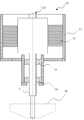
- FIG. 4 is a cross-sectional view of the electric motor 10 to which the rotor according to the first to second embodiments is applied.
- the stator 12 and the first and second bearings 13 and 14 are fixed to the housing 11 forming the outer shell, and the shaft 2 of the rotor 1 protruding outward from the housing 11 is the first and second bearings 13. It is configured to be rotatably supported by 14.
- the stator 12 is arranged on the outer peripheral portion of the magnet portion 3 with a preset gap.
- a rotational load portion 15 such as an impeller is attached to the protruding end of the shaft 2.
- the first and second bearings 13 and 14 are on one end side of the shaft 2 extending in the axial direction from the second balance member 5, from the side closer to the second balance member 5, the first and first bearings 13 and 14.
- a cantilever shaft structure is arranged in the order of 2 and the other end side of the shaft 2 is a free end, but the present disclosure is not limited to this. It may have a double-sided shaft structure in which the first bearing 13 is arranged on one end side of the shaft 2 and the second bearing 14 is arranged on the other end side of the shaft 2.
- FIG. 5 shows a schematic diagram of the swinging motion.
- the balance of each rotor is individually adjusted at the time of manufacturing so that the imbalance of the center of gravity becomes equal to or less than the allowable value.
- the mass balance in the radial direction is changed by partially cutting the first balance member 4 or the second balance member 5 installed at the end of the magnet portion 3.
- the imbalance of the center of gravity cannot be completely eliminated, so that a slight swinging motion actually occurs.
- the radial centrifugal force caused by the imbalance of the center of gravity generates a moment in the direction in which the shaft 2 supported by the first and second bearings 13 and 14 is tilted sideways.
- the distance between the first bearing 13 and the second bearing 14 is determined so that a sufficient reaction force can be obtained with respect to this moment.
- the rotor 1 When a swinging motion occurs in the rotor 1, the rotor 1 receives a load that is pulled toward the free end side in the axial direction. Since this axial load acts so that the position of the center of gravity of the rotor 1 is far from the first bearing 13, it becomes a factor of increasing the swinging motion. Further, the shatterproof member 6, which is a component that is not restrained with respect to the shaft 2, may be displaced in the axial direction when the holding force of the adhesive 7 is reduced.
- FIG. 7 is a diagram showing a positional relationship between the rotor 1 and the stator 12. As shown in FIG. 7, when the midpoint in the axial direction of the magnet portion 3 is A and the midpoint in the axial direction of the stator 12 is B, the stator 12 is closer to the first bearing 13 by the distance d. It is arranged like this. When arranged in this way, the rotor 1 receives a magnetic attraction force attracted in the direction of the first bearing 13 as well as a magnetic force in the circumferential direction in which rotational torque is applied from the stator 12. The magnetic attraction force acting in the axial direction cancels the axial load due to the swing and brings the center of gravity of the rotor 1 closer to the first bearing 13, so that the swing motion can be suppressed.
- the first balance member 4 having a diameter larger than the inner diameter of the shatterproof member 6 is arranged on the free end side of the swinging motion. Therefore, even if the shatterproof member 6 receives an axial load due to swinging, the first balance member 4 restrains the movement toward the free end side, so that the shatterproof member 6 is displaced in the axial direction and the center of gravity of the rotor is rotated. The reliability of the electric motor 10 can be improved without increasing the imbalance of the electric motor 10.
- the axial position of the shatterproof member 6 can be determined without using other positioning means, and the rotor 1 is rotating. Even if the shatterproof member 6 receives an axial load, it does not move to the first balance member 4.
- the shatterproof member 6 is magnetized after the first and second balance members 4 and 5 are press-fitted and fixed to the shaft 2. It can be inserted into 3 and the assemblability of the rotor 1 can be improved.
- the motor 10 according to the third embodiment adopts the cantilever shaft structure, the moment of the swinging motion acting to tilt the shaft 2 can be offset, and the vibration due to the swinging can be suppressed. In addition, it is possible to prevent the scattering prevention member 6 from falling off due to the swinging motion.
- the axial position of the rotor 1 with respect to the stator 12 is arranged so as to cancel the axial load due to the swinging motion by the magnetic attraction force, it is possible to provide the motor 10 having small vibration even when used at high speed rotation. it can.
- FIG. 8 is a cross-sectional view of the blower 30 according to the fourth embodiment.
- This blower applies any of the embodiments described in the first to third embodiments.
- the arrows in FIG. 8 represent the flow of air.
- the blower 30 is composed of a rotary load portion 15 which is a blower blade fixed to one end of a shaft 2 protruding from an electric motor 10 having a housing 11 as an outer shell, and a fan casing forming a blower path with a bracket 31 and a fan cover 34. ing.
- the bracket 31 is fixed to the housing 11, and the fan cover 34 is fixed so as to cover the bracket 31 and the rotational load portion 15.
- a partition plate 32 integrally formed with the stationary blade 33 is installed in the air passage formed between the bracket 31 and the fan cover 34.
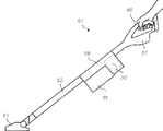
- FIG. 9 is a diagram showing an example of the configuration of the vacuum cleaner 61 using the blower 30 according to the fourth embodiment.
- the vacuum cleaner 61 includes a battery 67 as a DC power source, a blower 30, a dust collecting chamber 65, a sensor 68, a suction port 63, an extension pipe 62, and an operation unit 66. ..
- the vacuum cleaner 61 drives the blower 30 using the battery 67 as a power source, sucks the dust from the suction port 63, and sucks the dust into the dust collecting chamber 65 through the extension pipe 62.
- the operation unit 66 is held to operate the vacuum cleaner 61.
- FIG. 10 is a perspective view showing an example of the configuration of the hand dryer 90 as another application example of the blower 30 in the fourth embodiment.
- the hand dryer 90 includes a casing 91, a hand detection sensor 92, a water receiving portion 93, a drain container 94, a cover 96, a sensor 97, and an intake port 98.
- the sensor 97 is either a gyro sensor or a motion sensor.
- the hand dryer 90 has a blower 30 (not shown) in the casing 91.
- the hand dryer 90 has a structure in which water is blown off by blowing air from a blower by inserting a hand into the hand insertion portion 99 above the water receiving portion 93, and water is stored from the water receiving portion 93 into the drain container 94. There is.
- the blower 30 according to the fourth embodiment since it is composed of the motor 10 using the rotor 1 or 20, it is possible to obtain a blower that can be made smaller and lighter and has less vibration. Therefore, even when the blower 30 is applied to home appliances such as the vacuum cleaner 61 and the hand dryer 90, it is possible to provide products that are compact and lightweight and have low vibration.
- the configuration shown in the above-described embodiment shows an example of the contents of the present disclosure, can be combined with another known technique, and is configured without departing from the gist of the present disclosure. It is also possible to omit or change a part of.
Landscapes
- Engineering & Computer Science (AREA)
- Power Engineering (AREA)
- Connection Of Motors, Electrical Generators, Mechanical Devices, And The Like (AREA)
- Manufacture Of Motors, Generators (AREA)
- Permanent Field Magnets Of Synchronous Machinery (AREA)
Priority Applications (3)
| Application Number | Priority Date | Filing Date | Title |
|---|---|---|---|
| US17/642,435 US11962224B2 (en) | 2019-11-14 | 2019-11-14 | Rotor, motor, fan, and electric vacuum cleaner or hand dryer |
| PCT/JP2019/044691 WO2021095200A1 (ja) | 2019-11-14 | 2019-11-14 | ロータ、電動機、送風機及び電気掃除機又はハンドドライヤー |
| JP2021555720A JP7282200B2 (ja) | 2019-11-14 | 2019-11-14 | ロータ、電動機、送風機及び電気掃除機又はハンドドライヤー |
Applications Claiming Priority (1)
| Application Number | Priority Date | Filing Date | Title |
|---|---|---|---|
| PCT/JP2019/044691 WO2021095200A1 (ja) | 2019-11-14 | 2019-11-14 | ロータ、電動機、送風機及び電気掃除機又はハンドドライヤー |
Publications (1)
| Publication Number | Publication Date |
|---|---|
| WO2021095200A1 true WO2021095200A1 (ja) | 2021-05-20 |
Family
ID=75911530
Family Applications (1)
| Application Number | Title | Priority Date | Filing Date |
|---|---|---|---|
| PCT/JP2019/044691 Ceased WO2021095200A1 (ja) | 2019-11-14 | 2019-11-14 | ロータ、電動機、送風機及び電気掃除機又はハンドドライヤー |
Country Status (3)
| Country | Link |
|---|---|
| US (1) | US11962224B2 (https=) |
| JP (1) | JP7282200B2 (https=) |
| WO (1) | WO2021095200A1 (https=) |
Citations (3)
| Publication number | Priority date | Publication date | Assignee | Title |
|---|---|---|---|---|
| WO2008026268A1 (fr) * | 2006-08-31 | 2008-03-06 | Hitachi, Ltd. | Generateur et installation de production d'energie par turbines a gaz |
| JP2019110680A (ja) * | 2017-12-19 | 2019-07-04 | 三菱電機株式会社 | 回転電機のロータの製造方法及びスリーブ接着装置 |
| WO2019167153A1 (ja) * | 2018-02-28 | 2019-09-06 | 三菱電機株式会社 | 電動送風機、電気掃除機および手乾燥装置 |
Family Cites Families (5)
| Publication number | Priority date | Publication date | Assignee | Title |
|---|---|---|---|---|
| JPS58163255A (ja) * | 1982-03-24 | 1983-09-28 | Okuma Mach Works Ltd | 永久磁石式同期モ−タの回転子 |
| JP2673708B2 (ja) | 1988-08-05 | 1997-11-05 | アイチーエマソン電機株式会社 | 永久磁石型回転子 |
| JP3072851B2 (ja) | 1990-11-19 | 2000-08-07 | 株式会社日立製作所 | 超高速回転機の永久磁石回転子 |
| JP2001234927A (ja) | 1999-12-03 | 2001-08-31 | Nsk Ltd | 情報機器用小型モータ及びその小型モータ用転がり軸受 |
| GB201014073D0 (en) | 2010-08-24 | 2010-10-06 | Dyson Technology Ltd | Rotor core assembly |
-
2019
- 2019-11-14 US US17/642,435 patent/US11962224B2/en active Active
- 2019-11-14 JP JP2021555720A patent/JP7282200B2/ja active Active
- 2019-11-14 WO PCT/JP2019/044691 patent/WO2021095200A1/ja not_active Ceased
Patent Citations (3)
| Publication number | Priority date | Publication date | Assignee | Title |
|---|---|---|---|---|
| WO2008026268A1 (fr) * | 2006-08-31 | 2008-03-06 | Hitachi, Ltd. | Generateur et installation de production d'energie par turbines a gaz |
| JP2019110680A (ja) * | 2017-12-19 | 2019-07-04 | 三菱電機株式会社 | 回転電機のロータの製造方法及びスリーブ接着装置 |
| WO2019167153A1 (ja) * | 2018-02-28 | 2019-09-06 | 三菱電機株式会社 | 電動送風機、電気掃除機および手乾燥装置 |
Also Published As
| Publication number | Publication date |
|---|---|
| US20220345005A1 (en) | 2022-10-27 |
| JP7282200B2 (ja) | 2023-05-26 |
| JPWO2021095200A1 (https=) | 2021-05-20 |
| US11962224B2 (en) | 2024-04-16 |
Similar Documents
| Publication | Publication Date | Title |
|---|---|---|
| JP6783679B2 (ja) | モータ及びブロワ | |
| CN110679062B (zh) | 用于电机的定子 | |
| WO2021095200A1 (ja) | ロータ、電動機、送風機及び電気掃除機又はハンドドライヤー | |
| JP2008196480A (ja) | 軸流送風機 | |
| JP3446373B2 (ja) | 電動送風機のバランス修正方法 | |
| JP2003324893A (ja) | 防振モータの構造 | |
| JP2604038B2 (ja) | 遠心ポンプ | |
| JP2008190328A (ja) | 遠心式圧縮機 | |
| JP2013126267A (ja) | 回転電気機械および圧縮機 | |
| US12424889B2 (en) | Rotor, motor using the rotor, and electronic device | |
| JP4358722B2 (ja) | ブラシレスモータ | |
| WO2018066232A1 (ja) | 遠心送風機 | |
| JP2003199283A (ja) | 磁気結合型モータおよびそれを用いたポンプ | |
| JP2001165189A (ja) | 磁気カップリング | |
| JPH0865983A (ja) | 空気調和機の室内送風機 | |
| JP2000227094A (ja) | モータ及びターボ分子ポンプ | |
| JP2021025411A (ja) | ドライポンプの製造方法 | |
| JP2002039090A (ja) | 圧力発生装置及びターボ分子ポンプ | |
| JPS60125800A (ja) | 電動送風機 | |
| JP4827390B2 (ja) | 回転位置決め装置 | |
| JPH08154365A (ja) | モータ駆動回転機器 | |
| JP2000161291A (ja) | 電動送風機のバランス修正装置 | |
| JP4909720B2 (ja) | 軸方向空隙型電動機 | |
| JPH10117462A (ja) | ファン一体型モータ | |
| WO2021014874A1 (ja) | ブラシレスモータ |
Legal Events
| Date | Code | Title | Description |
|---|---|---|---|
| 121 | Ep: the epo has been informed by wipo that ep was designated in this application |
Ref document number: 19952843 Country of ref document: EP Kind code of ref document: A1 |
|
| ENP | Entry into the national phase |
Ref document number: 2021555720 Country of ref document: JP Kind code of ref document: A |
|
| NENP | Non-entry into the national phase |
Ref country code: DE |
|
| 122 | Ep: pct application non-entry in european phase |
Ref document number: 19952843 Country of ref document: EP Kind code of ref document: A1 |