WO2021095122A1 - 軸流ファン、送風装置、及び、冷凍サイクル装置 - Google Patents
軸流ファン、送風装置、及び、冷凍サイクル装置 Download PDFInfo
- Publication number
- WO2021095122A1 WO2021095122A1 PCT/JP2019/044363 JP2019044363W WO2021095122A1 WO 2021095122 A1 WO2021095122 A1 WO 2021095122A1 JP 2019044363 W JP2019044363 W JP 2019044363W WO 2021095122 A1 WO2021095122 A1 WO 2021095122A1
- Authority
- WO
- WIPO (PCT)
- Prior art keywords
- inner peripheral
- peripheral side
- cross
- edge portion
- straight line
- Prior art date
- Legal status (The legal status is an assumption and is not a legal conclusion. Google has not performed a legal analysis and makes no representation as to the accuracy of the status listed.)
- Ceased
Links
Images








Classifications
-
- F—MECHANICAL ENGINEERING; LIGHTING; HEATING; WEAPONS; BLASTING
- F04—POSITIVE - DISPLACEMENT MACHINES FOR LIQUIDS; PUMPS FOR LIQUIDS OR ELASTIC FLUIDS
- F04D—NON-POSITIVE-DISPLACEMENT PUMPS
- F04D29/00—Details, component parts, or accessories
- F04D29/26—Rotors specially for elastic fluids
- F04D29/32—Rotors specially for elastic fluids for axial flow pumps
- F04D29/38—Blades
- F04D29/384—Blades characterised by form
-
- F—MECHANICAL ENGINEERING; LIGHTING; HEATING; WEAPONS; BLASTING
- F05—INDEXING SCHEMES RELATING TO ENGINES OR PUMPS IN VARIOUS SUBCLASSES OF CLASSES F01-F04
- F05D—INDEXING SCHEME FOR ASPECTS RELATING TO NON-POSITIVE-DISPLACEMENT MACHINES OR ENGINES, GAS-TURBINES OR JET-PROPULSION PLANTS
- F05D2240/00—Components
- F05D2240/20—Rotors
- F05D2240/30—Characteristics of rotor blades, i.e. of any element transforming dynamic fluid energy to or from rotational energy and being attached to a rotor
- F05D2240/305—Characteristics of rotor blades, i.e. of any element transforming dynamic fluid energy to or from rotational energy and being attached to a rotor related to the pressure side of a rotor blade
-
- F—MECHANICAL ENGINEERING; LIGHTING; HEATING; WEAPONS; BLASTING
- F05—INDEXING SCHEMES RELATING TO ENGINES OR PUMPS IN VARIOUS SUBCLASSES OF CLASSES F01-F04
- F05D—INDEXING SCHEME FOR ASPECTS RELATING TO NON-POSITIVE-DISPLACEMENT MACHINES OR ENGINES, GAS-TURBINES OR JET-PROPULSION PLANTS
- F05D2250/00—Geometry
- F05D2250/20—Three-dimensional
- F05D2250/29—Three-dimensional machined; miscellaneous
- F05D2250/291—Three-dimensional machined; miscellaneous hollowed
-
- F—MECHANICAL ENGINEERING; LIGHTING; HEATING; WEAPONS; BLASTING
- F05—INDEXING SCHEMES RELATING TO ENGINES OR PUMPS IN VARIOUS SUBCLASSES OF CLASSES F01-F04
- F05D—INDEXING SCHEME FOR ASPECTS RELATING TO NON-POSITIVE-DISPLACEMENT MACHINES OR ENGINES, GAS-TURBINES OR JET-PROPULSION PLANTS
- F05D2250/00—Geometry
- F05D2250/70—Shape
- F05D2250/71—Shape curved
- F05D2250/711—Shape curved convex
Definitions
- the present invention relates to an axial fan provided with a plurality of blades, a blower provided with the axial fan, and a refrigeration cycle device provided with the blower.
- Patent Document 1 Conventionally, an axial fan having a plurality of thin blades on a cylindrical hub has been proposed (see, for example, Patent Document 1).
- the axial fan of Patent Document 1 is formed so that the outer chord length of the blade is longer than the hub chord length.
- the axial flow fan of Patent Document 1 has a straight outer peripheral blade shape with a curvature point of about 1/3 of the blade length connecting the hub portion and the outer peripheral portion of the blade in the radial cross section of the blade. It is configured in a shape, and the hub side is configured to be convex with respect to the wind side.
- the axial flow fan of Patent Document 1 Since the axial flow fan of Patent Document 1 has this configuration, the linear portion on the outer peripheral side and the convex portion on the hub side promote the inflow of the fluid in the radial direction flowing from the outer circumference of the blade, so that the blade is natural. It is disclosed as optimizing the surrounding fluid state. Therefore, the axial fan of Patent Document 1 can sufficiently exert the effects of improving fan efficiency and reducing noise, which are fan characteristics as a low-pressure propeller fan, and can reduce the period power consumption of the air conditioner. It can be reduced.
- the present invention is for solving the above-mentioned problems, and is an axial fan in which fluid is suppressed from leaking from the blade surface on the positive pressure side at the outer peripheral end of the blade and the growth of the blade end vortex is suppressed. It is an object of the present invention to provide a blower equipped with an axial fan and a refrigeration cycle device equipped with the blower.
- the axial flow fan according to the present invention includes a hub that is rotationally driven to form a rotating shaft, and a wing that is connected to the hub and has a front edge portion and a trailing edge portion. It has a flow control unit that is formed in at least a part between the two and controls the flow of fluid on the positive pressure surface, and the flow control unit has an inner edge portion of a region forming an edge portion on the inner peripheral side and an outer peripheral side.
- the region has a cross section perpendicular to the rotation axis between the region outer edge portion forming the edge portion and the region inner edge portion and the region outer edge portion, and a cross section curved so that the positive pressure surface is recessed.
- the virtual region intermediate line which is an intermediate position between the inner edge portion and the outer edge portion of the region, is formed so as to be located on the outer peripheral side of the virtual blade intermediate line, which is the intermediate position of the blade in the radial direction, and is formed in the cross section.
- the blower according to the present invention includes an axial fan having the above configuration, a drive source for applying a driving force to the axial fan, and a casing for accommodating the axial fan and the drive source.
- the refrigeration cycle device includes a blower having the above configuration and a refrigerant circuit having a condenser and an evaporator, and the blower blows air to at least one of the condenser and the evaporator. ..
- the virtual region intermediate line which is an intermediate position between the inner edge portion of the region and the outer edge portion of the region, is located on the outer peripheral side of the virtual blade intermediate line, which is the intermediate position of the blade in the radial direction.
- the virtual blade intermediate line By being formed so as to be located, it is possible to attract the flow of fluid to the outer peripheral side of the blade that works with high efficiency. Since the amount of protrusion of the cross section of the axial fan increases from the front edge side to the trailing edge side, the fluid on the positive pressure surface side easily flows along the cross section, and the positive pressure surface side is easily flowed along the cross section. Fluid flow is concentrated. Therefore, the axial fan can suppress the leakage of fluid from the blade surface on the positive pressure surface side at the outer peripheral end of the blade, and can suppress the growth of the blade end vortex.
- FIG. 1 It is a front view which shows the schematic structure of the axial flow fan which concerns on Embodiment 1.
- FIG. It is a conceptual diagram which shows the meridional plane of the axial fan which concerns on Embodiment 1.
- FIG. It is a front view which shows the schematic structure of the blade of the axial flow fan which concerns on Embodiment 1.
- FIG. It is a front view which shows the schematic structure of the blade of the axial flow fan which concerns on a comparative example.
- FIG. 1 It is a front view which shows the schematic structure of the blade of the axial fan which concerns on another comparative example.
- FIG. 2 It is a front view which shows the schematic structure of the blade of the axial flow fan which concerns on Embodiment 2.
- FIG. It is a front view which shows the schematic structure of the blade of the axial flow fan which concerns on Embodiment 3.
- FIG. It is a front view which shows the schematic structure of the blade of the axial flow fan which concerns on Embodiment 4.
- FIG. It is a front view which shows the schematic structure of the blade of the axial flow fan which concerns on embodiment 5.
- FIG. It is a conceptual diagram which shows the meridional plane of the axial fan which concerns on Embodiment 6.
- FIG. 5 is a conceptual diagram of an outdoor unit provided with an axial fan according to a tenth embodiment as viewed from the upper surface side.
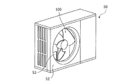
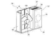
- FIG. 5 is a conceptual diagram of an outdoor unit provided with an axial fan according to the eleventh embodiment as viewed from the upper surface side. It is a schematic diagram of the refrigeration cycle apparatus which concerns on Embodiment 12. It is a perspective view when the outdoor unit which is a blower is seen from the air outlet side. It is a figure for demonstrating the structure of the outdoor unit from the upper surface side. It is a figure which shows the state which the fan grill is removed from the outdoor unit. It is a figure which shows the internal structure by removing a fan grill, a front panel, etc. from an outdoor unit.
- FIG. 1 is a front view showing a schematic configuration of an axial fan 100 according to the first embodiment.
- the rotation direction DR indicated by the arrow in the figure indicates the direction in which the axial fan 100 rotates.
- the circumferential direction CD indicated by the double-headed arrow in the figure indicates the circumferential direction of the axial fan 100.
- the circumferential CD includes a rotation direction DR and a direction opposite to the rotation direction DR.
- the back side with respect to the paper surface is the upstream side in the direction in which the fluid flows with respect to the axial fan 100
- the front side with respect to the paper surface is the downstream side in the direction in which the fluid flows with respect to the axial flow fan 100. ..
- the upstream side with respect to the axial fan 100 is the air suction side with respect to the axial fan 100
- the downstream side with respect to the axial fan 100 is the air outlet side with respect to the axial fan 100.
- the axial fan 100 is a device that forms a fluid flow, and is used in, for example, an air conditioner or a ventilation device.
- the axial flow fan 100 forms a fluid flow by rotating in the rotation direction DR about the rotation axis RA.
- the fluid is, for example, a gas such as air.
- the axial flow fan 100 includes a hub 10 provided on the rotating shaft RA, and a plurality of blades 20 connected to the hub 10.
- the axial fan 100 includes a so-called bossless type fan in which the front edge side and the trailing edge side of adjacent blades 20 of a plurality of blades 20 are connected so as to form a continuous surface without a boss.
- the hub 10 is rotationally driven by a motor (not shown) or the like to form a rotary shaft RA.
- the hub 10 rotates about the rotation axis RA.
- the rotational direction DR of the axial fan 100 is the counterclockwise direction indicated by the arrow in FIG.
- the rotation direction DR of the axial flow fan 100 is not limited to counterclockwise rotation, and can be rotated clockwise by changing the mounting angle of the blade 20 or the direction of the blade 20. You may.
- the hub 10 is connected to a rotating shaft of a drive source such as a motor (not shown).
- the hub 10 may be formed in a cylindrical shape or a plate shape, for example.
- the hub 10 may be connected to the rotation shaft of the drive source as described above, and its shape is not limited.
- the wings 20 are formed so as to extend radially outward from the hub 10.
- the plurality of blades 20 are arranged radially outward from the hub 10.
- the plurality of wings 20 are provided apart from each other in the circumferential direction CD. In the first embodiment, the embodiment in which the number of wings 20 is three is illustrated, but the number of wings 20 is not limited to three.
- the wing 20 has a front edge portion 21, a trailing edge portion 22, an outer peripheral edge portion 23, and an inner peripheral edge portion 24.
- the front edge portion 21 is formed on the wing 20 on the forward side of the rotation direction DR. That is, the front edge portion 21 is located forward with respect to the trailing edge portion 22 in the rotation direction DR.
- the front edge portion 21 is located upstream of the trailing edge portion 22 in the direction in which the generated fluid flows.
- the trailing edge portion 22 is formed on the wing 20 on the reverse side of the rotation direction DR. That is, the trailing edge portion 22 is located rearward with respect to the front edge portion 21 in the rotation direction DR.
- the trailing edge portion 22 is located on the downstream side of the front edge portion 21 in the direction in which the generated fluid flows.
- the axial fan 100 has a front edge portion 21 as a blade end portion facing the rotational direction DR of the axial flow fan 100, and a trailing edge portion 22 as a blade end portion opposite to the front edge portion 21 in the rotational direction DR. have.
- the outer peripheral edge portion 23 is a portion extending back and forth in the rotation direction DR so as to connect the outermost peripheral portion of the front edge portion 21 and the outermost peripheral portion of the trailing edge portion 22.
- the outer peripheral edge portion 23 is formed in an arc shape when viewed in a direction parallel to the rotation axis RA.
- the outer peripheral edge portion 23 is not limited to the configuration formed in an arc shape when viewed in a direction parallel to the rotation axis RA.
- the outer peripheral edge portion 23 is located at the end portion on the outer peripheral side in the radial direction (Y-axis direction) of the axial flow fan 100.
- the inner peripheral edge portion 24 is a portion extending back and forth in the rotation direction DR so as to connect the innermost peripheral portion of the front edge portion 21 and the innermost peripheral portion of the trailing edge portion 22.
- the inner peripheral edge portion 24 is formed in an arc shape when viewed in a direction parallel to the rotation axis RA.
- the inner peripheral edge portion 24 is not limited to the configuration formed in an arc shape when viewed in a direction parallel to the rotation axis RA.
- the inner peripheral edge portion 24 is located at the end portion on the inner peripheral side in the radial direction (Y-axis direction) of the axial flow fan 100.
- the inner peripheral edge portion 24 of the wing 20 is connected to the hub 10, such as being integrally formed with the hub 10.
- the wing 20 is formed so as to be inclined with respect to a plane perpendicular to the rotation axis RA.
- the blade 20 conveys the fluid by pushing the fluid existing between the blades 20 with the blade surface as the axial fan 100 rotates.
- the surface of the blade surface on which the fluid is pushed and the pressure rises is referred to as the positive pressure surface 25, and the surface on the back surface of the positive pressure surface 25 on which the pressure decreases is referred to as the negative pressure surface 26.
- the surface on the upstream side of the blade 20 is the negative pressure surface 26 and the surface on the downstream side is the positive pressure surface 25 with respect to the direction in which the fluid flows.
- the surface of the wing 20 on the front side of the wing 20 is the positive pressure surface 25, and the surface on the back side of the wing 20 is the negative pressure surface 26.
- FIG. 2 is a conceptual diagram showing the meridional plane of the axial fan 100 according to the first embodiment.
- FIG. 2 shows the shape of the axial fan 100 when rotationally projected onto the meridional surface including the rotary shaft RA and the blade 20.
- the blade 20 when rotationally projected onto the meridional plane is indicated by the blade projection portion 20p
- the hub 10 when rotationally projected onto the meridional plane is indicated by the hub projection portion 10p.
- the front edge projection line 21p is a rotation projection of the front edge portion 21 around the rotation axis RA on the meridional surface including the rotation axis RA.
- the trailing edge projection line 22p is obtained by rotationally projecting the trailing edge portion 22 around the rotation axis RA on the meridional surface including the rotation axis RA.
- the outer edge projection line 23p is obtained by rotationally projecting the outer peripheral edge portion 23 around the rotation axis RA on the meridional surface including the rotation axis RA.
- the inner edge projection line 24p is obtained by rotationally projecting the inner peripheral edge portion 24 around the rotation axis RA on the meridional surface including the rotation axis RA.
- the flow direction AF indicated by the vertical striped arrows by hatching in FIG. 2 represents the direction in which the fluid flows with respect to the axial flow fan 100.
- the axial direction AD indicated by the white arrow in FIG. 2 represents the axial direction of the rotation axis RA.
- the viewpoint VP indicated by the horizontal striped arrow by hatching in FIG. 2 represents the direction of the line of sight when viewed in a direction parallel to the rotation axis RA.
- the Y-axis shown in FIGS. 1 and 2 represents the radial direction of the axial flow fan 100 with respect to the rotation axis RA.
- the Y2 side of the axial fan 100 with respect to the Y1 side is the inner peripheral side of the axial fan 100
- the Y1 side of the axial fan 100 with respect to the Y2 side is the outer peripheral side of the axial fan 100.
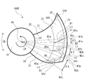
- FIG. 3 is a front view showing a schematic configuration of the blade 20 of the axial fan 100 according to the first embodiment.
- the airflow FL indicated by the white arrow in FIG. 3 indicates the airflow on the downstream side of the blade 20.
- the size of the airflow FL indicated by the white arrow conceptually represents the air volume, and the magnitude of the airflow FL indicated by the white arrow represents the amount of airflow.
- the blade length 27 is the distance between the inner peripheral edge portion 24 and the outer peripheral edge portion 23, and the virtual blade intermediate line 28 indicates the center of the blade length 27 in the radial direction. That is, the virtual wing intermediate line 28 indicates an intermediate position of the distance between the inner peripheral edge portion 24 and the outer peripheral edge portion 23.
- the blade length 27 has the same length at any position of the circumferential CD of the axial fan 100. That is, the blade 20 has a constant blade length 27 in the range between the front edge portion 21 and the trailing edge portion 22, and is the outer peripheral edge when viewed in a direction parallel to the axial direction AD of the rotation axis RA.
- the shape of the portion 23 is formed to be an arc.
- the wing 20 is not limited to a shape in which the length of the wing length 27 is constant in the range between the front edge portion 21 and the trailing edge portion 22.
- the blade 20 may be formed so that the length of the blade length 27 differs depending on the position of the circumferential CD of the axial fan 100. That is, the shape of the outer peripheral edge portion 23 of the blade 20 does not have to be an arc when viewed in a direction parallel to the axial direction AD of the rotation axis RA.
- the position P1, the position P2, and the position P3 represented by the dotted lines represent the positions of the cross sections perpendicular to the rotation axis RA, respectively.
- the position P1, the position P2, and the position P3 are located in the order of the position P1, the position P2, and the position P3 from the upstream side to the downstream side in the direction in which the fluid flows in the axial direction AD of the rotation axis RA.
- the portions located on the cross section represented by the position P1 are the portions located at the same position in the axial direction AD of the rotating shaft RA, respectively.
- the portions located on the cross section represented by the position P2 are portions located at the same position in the axial direction AD of the rotation axis RA, respectively.
- the portions located on the cross section represented by the position P3 are the portions located at the same position in the axial direction AD of the rotation axis RA, respectively.
- the relationship between the portion located on the cross section represented by the position P1, the portion located on the cross section represented by the position P2, and the portion located on the cross section represented by the position P3 is the axis of the rotation axis RA, respectively. It is a part located at a different position in the direction AD.
- the position P1, the position P2, and the position P3 indicate the relative positional relationship between the front edge portion 21 and the trailing edge portion 22 of the position P1, the position P2, and the position P3. Further, in the first embodiment, the configuration of the three positions P1 to P3 is described, but the relationship between the positions P1 to P3 does not apply only to the three positions P1 to P3. It also applies to relationships at four or more locations.
- the blade 20 has a flow control unit 30.
- the flow control unit 30 is a portion of the blade 20 that controls the flow direction of the fluid flowing on the positive pressure surface 25.
- the flow control unit 30 is formed in at least a part between the front edge portion 21 and the trailing edge portion 22, and is formed with a constant width in the radial direction which is the direction perpendicular to the rotation axis RA. Has been done.
- the flow control unit 30 is a region formed in an arc shape when viewed in a direction parallel to the rotation axis RA.
- the flow control unit 30 has a region inner edge portion 31 that forms an inner peripheral side edge portion and a region outer edge portion 32 that forms an outer peripheral side edge portion.
- the region outer edge portion 32 is located on the outer peripheral side of the virtual blade intermediate line 28 in the radial direction of the axial fan 100.
- the region inner edge portion 31 is located on the outer peripheral side of the virtual blade intermediate line 28 in the radial direction of the axial fan 100. However, the region inner edge portion 31 may be located on the inner peripheral side of the virtual blade intermediate line 28 in the radial direction of the axial fan 100.
- the region inner edge portion 31 is formed in an arc shape, and is formed so that the distance from the rotation axis RA is constant in the radial direction of the axial fan 100.
- the region outer edge portion 32 is formed in an arc shape, and is formed so that the distance from the rotation shaft RA is constant in the radial direction of the axial flow fan 100.
- the flow control unit 30 is a region formed between the region inner edge portion 31 and the region outer edge portion 32. Further, the flow control unit 30 is formed along the circumferential direction CD of the axial fan 100 at least in a part between the front edge portion 21 and the trailing edge portion 22. That is, the flow control unit 30 is formed so as to extend in the radial direction of the axial fan 100 and extend in the circumferential direction CD in the blade 20.
- the flow control unit 30 is formed to have a constant radial width at any position of the circumferential CD of the axial fan 100. That is, the flow control unit 30 is formed so that the distance between the region inner edge portion 31 and the region outer edge portion 32 in the radial direction is constant at any position of the circumferential CD of the axial fan 100.
- the region inner edge portion 31 and the region outer edge portion 32 are not limited to the configuration formed so that the distance from the rotation axis RA is constant in the radial direction of the axial flow fan 100.
- the axial flow fan 100 is formed to have a width having a different radial width depending on the position of the circumferential CD of the axial flow fan 100.
- the flow control unit 30 is located relatively on the outer peripheral side in the radial direction of the blade 20.
- the virtual region intermediate line 33 of the flow control unit 30 is formed so as to be located on the outer peripheral side of the virtual blade intermediate line 28 between the outer peripheral edge portion 23 and the inner peripheral edge portion 24. That is, the virtual region intermediate line 33, which is an intermediate position between the region inner edge portion 31 and the region outer edge portion 32, is located on the outer peripheral side of the virtual blade intermediate line 28, which is an intermediate position of the blade 20 in the radial direction. It is formed.
- the flow control unit 30 has a blade cross section in the radial direction in a direction opposite to the rotation direction DR of the axial fan 100.
- the wing plate is curved and warped so as to be convex. Further, the flow control unit 30 is convex to the upstream side in the flow direction of the fluid formed by the blade 20 in at least a part of the circumferential direction CD between the front edge portion 21 and the trailing edge portion 22 of the blade 20.
- the wing plate is curved and warped. That is, the flow control unit 30 is formed so that the positive pressure surface 25 side of the blade 20 is recessed in at least a part of the circumferential CD in the axial fan 100.
- the cross section S shown by the dotted line in FIG. 3 shows the cross section of the blade 20 in the flow control unit 30.
- the cross section S shows a cross section of the flow control unit 30 in a direction perpendicular to the rotation axis RA.
- the flow control unit 30 provides a curved cross section S between the region inner edge portion 31 and the region outer edge portion 32 so that the positive pressure surface 25 side is concave and the negative pressure surface 26 side is convex as a cross section perpendicular to the rotation axis RA. Have.
- the cross-sectional portion S is curved so as to be convex in the direction opposite to the rotation direction DR.
- the cross-sectional portion S is curved so as to be convex toward the upstream side in the direction AF in which the fluid flows.
- the cross-sectional portion S is curved so that the positive pressure surface 25 side is concave and the negative pressure surface 26 side is convex.
- the inner peripheral side end portion which is one end portion of the cross-sectional portion S is the region inner edge portion 31, and the outer peripheral side which is the other end portion of the cross-sectional portion S.
- the end of the region is the outer edge of the region 32.
- the cross section S of the blade 20 may be formed so that the positive pressure surface 25 side is recessed, and the shape of the negative pressure surface 26 side is not limited.
- the cross-sectional portion S of the blade 20 may be formed so that the positive pressure surface 25 side is convex toward the upstream side, and the negative pressure surface 26 side.
- the shape is not limited.
- the cross-sectional portion S1 shown by the dotted line in FIG. 3 shows the cross-sectional portion S of the blade 20 in the flow control unit 30 at the position P1 shown in FIG.
- the cross-sectional portion S2 shown by the dotted line in FIG. 3 shows the cross-sectional portion S of the blade 20 in the flow control unit 30 at the position P2 shown in FIG.
- the cross-sectional portion S3 shown by the dotted line in FIG. 3 shows the cross-sectional portion S of the blade 20 in the flow control unit 30 at the position P3 shown in FIG.
- the cross section S1 shows the cross section of the flow control unit 30 in the direction perpendicular to the rotation axis RA at the position P1 in the axial direction AD.
- the cross section S2 shows the cross section of the flow control unit 30 in the direction perpendicular to the rotation axis RA at the position P2 in the axial direction AD.
- the cross section S3 shows the cross section of the flow control unit 30 in the direction perpendicular to the rotation axis RA at the position P3 in the axial direction AD.
- the end on the inner peripheral side which is one end of the cross section S1, the cross section S2, and the cross section S3 is the region inner edge portion 31, and the cross section S1,
- the outer peripheral edge of the cross section S2 and the other end of the cross section S3 is the region outer edge 32.
- the cross section S1, the cross section S2, and the cross section S3 of the flow control unit 30 are the cross section S1, the cross section S2, and the cross section from the upstream side to the downstream side in the direction in which the fluid flows in the axial direction AD of the rotation axis RA. It is a cross-sectional portion S located in the order of the portion S3.
- the cross-section portion S1, the cross-section portion S2, and the cross-section portion S3 of the flow control unit 30 are the cross-section portion S1 and the cross-section from the front edge portion 21 to the trailing edge portion 22 in the circumferential direction CD of the axial flow fan 100. It is a cross-section portion S located in the order of the portion S2 and the cross-section portion S3.
- the straight line connecting the region inner edge portion 31 and the region outer edge portion 32 is defined as the cross-sectional straight line W.
- the distance from the cross-sectional straight line W connecting the region inner edge portion 31 and the region outer edge portion 32 to the positive pressure surface 25 located at the farthest position in the normal direction is defined as the protrusion amount L.
- the protrusion amount L is the distance from the cross-sectional straight line W to the deepest portion 35 at the position where the blade 20 is most convex in the normal direction in the cross-sectional portion S.
- the deepest portion 35 is a portion of the cross-sectional portion S of the flow control unit 30 where the positive pressure surface 25 side is the most recessed. That is, the deepest portion 35 is a portion of the cross-sectional portion S of the flow control unit 30 where the distance between the cross-sectional straight line W and the positive pressure surface 25 is the longest. In other words, the deepest portion 35 is a portion of the cross-sectional portion S of the flow control unit 30 where the negative pressure surface 26 side is most protruding, and is a convex apex portion constituting the cross-sectional portion S.
- the straight line connecting the region inner edge portion 31 and the region outer edge portion 32 is defined as the cross section straight line W1.
- the distance from the cross-sectional straight line W1 connecting the region inner edge portion 31 and the region outer edge portion 32 to the positive pressure surface 25 located at the farthest position in the normal direction is defined as the protrusion amount L1.
- the protrusion amount L1 is the distance from the cross-sectional straight line W1 to the deepest portion 35a at the position where the blade 20 is most convex in the normal direction in the cross-sectional portion S1.
- the deepest portion 35a is a portion of the cross-sectional portion S1 of the flow control unit 30 where the positive pressure surface 25 side is the most recessed. That is, the deepest portion 35a is a portion in the cross-sectional portion S1 of the flow control unit 30 where the distance between the cross-sectional straight line W1 and the positive pressure surface 25 is the longest. In other words, the deepest portion 35a is a portion of the cross-sectional portion S1 of the flow control unit 30 where the negative pressure surface 26 side is most protruding, and is a convex apex portion constituting the cross-sectional portion S1.
- the straight line connecting the region inner edge portion 31 and the region outer edge portion 32 is defined as the cross section straight line W2.
- the distance from the cross-sectional straight line W2 connecting the region inner edge portion 31 and the region outer edge portion 32 to the positive pressure surface 25 located at the farthest position in the normal direction is defined as the protrusion amount L2.
- the protrusion amount L2 is the distance from the cross-sectional straight line W2 to the deepest portion 35b at the position where the blade 20 is most convex in the normal direction in the cross-sectional portion S2.
- the deepest portion 35b is a portion of the cross-sectional portion S2 of the flow control unit 30 where the positive pressure surface 25 side is the most recessed. That is, the deepest portion 35b is a portion in the cross-sectional portion S2 of the flow control unit 30 where the distance between the cross-sectional straight line W2 and the positive pressure surface 25 is the longest. In other words, the deepest portion 35b is a portion of the cross-sectional portion S2 of the flow control unit 30 where the negative pressure surface 26 side is most protruding, and is a convex apex portion constituting the cross-sectional portion S2.
- the straight line connecting the region inner edge portion 31 and the region outer edge portion 32 is defined as the cross section straight line W3.
- the distance from the cross-sectional straight line W3 connecting the region inner edge portion 31 and the region outer edge portion 32 to the positive pressure surface 25 located at the farthest position in the normal direction is defined as the protrusion amount L3.
- the protrusion amount L3 is the distance from the cross-sectional straight line W3 to the deepest portion 35c at the position where the blade 20 is most convex in the normal direction in the cross-sectional portion S3.
- the deepest portion 35c is a portion of the cross-sectional portion S3 of the flow control unit 30 where the positive pressure surface 25 side is the most recessed. That is, the deepest portion 35c is a portion in the cross-sectional portion S3 of the flow control unit 30 where the distance between the cross-sectional straight line W3 and the positive pressure surface 25 is the longest. In other words, the deepest portion 35c is a portion of the cross-sectional portion S3 of the flow control unit 30 where the negative pressure surface 26 side is most protruding, and is a convex apex portion constituting the cross-sectional portion S3.
- the flow control unit 30 of the wing 20 is curved between the front edge portion 21 and the trailing edge portion 22 so that the protrusion amount L increases from the front edge portion 21 toward the trailing edge portion 22. Is formed. That is, the flow control unit 30 of the wing 20 increases the curvature of the wing 20 toward the upstream side from the front edge portion 21 to the trailing edge portion 22 between the front edge portion 21 and the trailing edge portion 22. It is formed. In other words, in the flow control unit 30 of the wing 20, the depth of the recess on the positive pressure surface 25 side increases from the front edge portion 21 to the trailing edge portion 22 between the front edge portion 21 and the trailing edge portion 22. It is formed to be large.
- the flow control unit 30 of the blade 20 is formed so that the protrusion amount L2 is larger than the protrusion amount L1 and the protrusion amount L3 is larger than the protrusion amount L2.
- the flow control unit 30 of the blade 20 is formed so as to satisfy the relationship of protrusion amount L1 ⁇ protrusion amount L2 ⁇ projection amount L3 between the front edge portion 21 and the trailing edge portion 22.
- the protrusion amount L on the trailing edge portion 22 side is larger than the protrusion amount L on the front edge portion 21 side in the circumferential direction CD. It is formed.
- the virtual region intermediate line 33 which is an intermediate position between the region inner edge portion 31 and the region outer edge portion 32, is located on the outer peripheral side of the virtual blade intermediate line 28, which is the intermediate position of the blade in the radial direction. It is formed to do. Further, the axial flow fan 100 is formed so that the protrusion amount L of the cross-sectional portion S increases from the front edge portion 21 side toward the trailing edge portion 22 side. Therefore, in the axial fan 100, the fluid on the positive pressure surface 25 side easily flows along the cross section S, and the fluid flow MF on the positive pressure surface 25 side is concentrated on the cross section S.
- the axial flow fan 100 can avoid attracting an excessive fluid to the outer peripheral side of the blade 20, suppresses the fluid from leaking from the blade surface on the positive pressure surface 25 side at the outer peripheral end of the blade 20, and the blade.
- the growth of end vortices can be suppressed.
- the blade tip vortex is an air vortex generated at the end of the blade 20 due to the pressure difference generated between the positive pressure surface 25 and the negative pressure surface 26 of the blade 20. Since the generation of the blade tip vortex leads to the consumption of extra energy, the efficiency of the axial fan 100 can be improved and the power consumption can be reduced by suppressing the generation of the blade tip vortex. Further, since the blade tip vortex generates noise, it is possible to suppress the generation of noise due to the rotation of the blade 20 by suppressing the generation of the blade tip vortex.
- the virtual region intermediate line 33 which is an intermediate position between the region inner edge portion 31 and the region outer edge portion 32, is inside the blade 20. It is located on the outer peripheral side of the virtual wing intermediate line 28, which is an intermediate position between the peripheral edge portion 24 and the outer peripheral edge portion 23. Since the axial fan 100 has a cross section S curved so that the positive pressure surface 25 is recessed on the outer peripheral side of the blade 20, as shown in the fluid flow MF of FIG. 3, from the inner peripheral side of the cross section S. The fluid can be attracted to the cross-sectional portion S on the outer peripheral side, which works with high efficiency. As shown in FIG.
- the axial fan 100 in the axial fan 100, the amount of airflow FL flowing on the outer peripheral side of the blade 20 that works with high efficiency is larger than the amount of airflow FL flowing on the inner peripheral side of the blade 20. Therefore, the axial fan 100 can work more efficiently than the axial fan in which a large amount of fluid flows on the inner peripheral side of the blade 20, so that the power consumption required by the axial fan 100 is reduced. can do.
- FIG. 4 is a front view showing a schematic configuration of a blade 20L of an axial fan 100L according to a comparative example.
- the flow control unit 30L of the blade 20L has a cross-sectional portion SL.
- the cross section SL shows a cross section of the flow control unit 30L in a direction perpendicular to the rotation axis RA.
- the cross section SL1 is the cross section SL at the position P1 in FIG. 2
- the cross section SL2 is the cross section SL at the position P2 in FIG. 2
- the cross section SL3 is the cross section SL at the position P3 in FIG. Is.
- the cross-sectional portion SL on the outer peripheral side of the blade is not curved and has a linear shape.
- the cross-sectional portion SL on the outer peripheral side of the blade is not curved and is formed in a linear shape, the flow of fluid toward the outer peripheral side of the blade cannot be drawn to the inner peripheral side, and the outer circumference of the blade 20L. There is a risk of fluid leaking at the edges.
- the fluid flow on the positive pressure surface 25 side of the axial fan 100L gradually moves in the radial direction of the blade 20 with a radial component as it goes from the upstream side to the downstream side in the fluid flow direction. Therefore, by adopting the shape of the blade 20 having the cross-sectional portion S like the axial flow fan 100 according to the first embodiment, the axial flow fan 100 according to the first embodiment is excessive toward the outer peripheral side of the blade 20. It is possible to avoid the attraction of various fluids. Further, in the axial flow fan 100, since the flow is concentrated on the cross section S of the blade 20, fluid is suppressed from leaking from the blade surface on the positive pressure surface 25 side at the outer peripheral end of the blade 20, and the growth of the blade tip vortex is suppressed. can do.
- the cross section SL is not formed in a convex shape in order to suppress the blade tip vortex of the blade 20L, and the axial flow fan 100L is oriented so as to draw the fluid flow toward the inner peripheral edge portion 24 side.
- the front edge portion 21 to the trailing edge portion 22 are formed without any change in unevenness.
- the axial fan 100L may be able to draw the fluid flow toward the inner peripheral edge portion 24 side and suppress the leakage of the fluid generated at the outer peripheral end of the blade 20.
- the axial fan 100L cannot increase the load on the outer peripheral side of the blade 20 that works efficiently, and the power consumption of the axial fan 100 cannot be sufficiently reduced.
- the axial flow fan 100L draws the fluid to the inner peripheral edge portion 24 side, the maximum wind speed region MA in which the fluid flows in a concentrated manner on the positive pressure surface 25 side is generated.
- the amount of the airflow FL that flows out concentrated in the maximum wind speed region MA is larger than the amount of the airflow FL on the inner peripheral edge portion 24 side and the outer peripheral edge portion 23 side of the blade 20. Therefore, the axial fan 100L has a large energy loss due to collision with a structure such as a grill located on the downstream side of the maximum wind speed region MA, causing noise deterioration and deterioration of power consumption of the axial fan 100L. There is a risk of inviting.
- the axial fan 100 according to the first embodiment increases the wind speed of the cross-sectional portion S located on the outer peripheral side in the radial direction. Therefore, the axial fan 100 according to the first embodiment can make the distribution of the wind speed at which the flowing fluid is blown out uniform in the region on the outer peripheral side of the maximum wind speed region ML in the radial direction. Therefore, the axial fan 100 according to the first embodiment can suppress energy loss due to collision with a structure such as a grill located on the downstream side. Further, the axial fan 100 according to the first embodiment can reduce noise due to collision with a structure such as a grill located on the downstream side, and can reduce the required power consumption of the axial fan 100. it can.
- FIG. 5 is a front view showing a schematic configuration of a blade 20R of an axial fan 100R according to another comparative example.
- the flow control unit 30R of the blade 20R has a cross-sectional portion SR.
- the cross section SR shows the cross section of the flow control unit 30R in the direction perpendicular to the rotation axis RA.
- the cross section SR1 is the cross section SR at the position P1 in FIG. 2
- the cross section SR2 is the cross section SR at the position P2 in FIG. 2
- the cross section SR3 is the cross section SR at the position P3 in FIG. Is.
- the cross-sectional portion SR of the axial flow fan 100R according to the comparative example is curved so as to be convex in the direction opposite to the rotation direction DR.
- the cross-sectional portion SR is curved so that the positive pressure surface 25 side is concave and the negative pressure surface 26 side is convex.
- the axial flow fan 100R according to the comparative example has a cross-sectional portion SR that is convex from the downstream side to the upstream side in the fluid flow direction, from the inner peripheral side to the outer peripheral side that works with high efficiency.
- the fluid can be attracted to a certain cross-sectional portion S, and the load on the outer peripheral side that works with high efficiency can be increased.
- the axial flow fan 100R is formed with a uniform protrusion amount L from the front edge portion 21 to the trailing edge portion 22, the attraction of the fluid flow MB to the outer peripheral side becomes excessive.
- the amount of airflow FL flowing on the outer peripheral edge portion 23 side of the wing 20 increases from the inner peripheral edge portion 24 side of the wing 20 toward the outer peripheral edge portion 23 side. It is larger than the amount of airflow FL. Therefore, in the axial flow fan 100R, a fluid flow MB leaks at the outermost periphery of the blade 20, causing noise deterioration due to the growth of the blade tip vortex, or deterioration of power consumption of the axial flow fan 100R. May cause it.
- the protrusion amount L of the cross-sectional portion S increases from the front edge portion 21 side to the trailing edge portion 22 side in the direction in which the fluid flows.
- the fluid on the positive pressure surface 25 side easily flows along the cross section S, and the fluid flow on the positive pressure surface 25 side is concentrated on the cross section S. Therefore, in the axial fan 100 according to the first embodiment, the fluid is suppressed from leaking from the blade surface on the positive pressure surface 25 side at the outer peripheral end of the blade 20, and the growth of the blade end vortex can be suppressed.
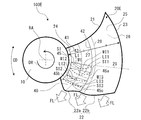
- FIG. 6 is a front view showing a schematic configuration of the blade 20A of the axial fan 100A according to the second embodiment. The detailed configuration of the blade 20A will be described with reference to FIG. The parts having the same configuration as the axial fan 100 of FIGS. 1 to 3 are designated by the same reference numerals, and the description thereof will be omitted.
- the axial fan 100A according to the second embodiment specifies the position of the deepest portion 35 of the flow control unit 30A.
- the deepest portion 35 is the portion of the cross-sectional portion S of the flow control unit 30 where the positive pressure surface 25 side is the most recessed. Further, the deepest portion 35 is a portion of the cross section S of the flow control unit 30 where the negative pressure surface 26 side is most protruding, and is a convex apex portion constituting the cross section S.
- the deepest portion 35a is the deepest portion 35 of the cross-sectional portion S1 in the flow control unit 30A.
- the deepest portion 35b is the deepest portion 35 of the cross-sectional portion S2 in the flow control unit 30A.
- the deepest portion 35c is the deepest portion 35 of the cross-sectional portion S3 in the flow control unit 30A.
- the cross section S1, the cross section S2, and the cross section S3 of the flow control unit 30A are the cross section S1, the cross section S2, and the cross section from the front edge portion 21 to the trailing edge portion 22 in the circumferential direction CD of the axial flow fan 100A. It is a cross-sectional portion S located in the order of the portion S3.
- the distance R1 shown in FIG. 6 is the distance between the rotating shaft RA and the deepest portion 35a in the radial direction of the axial fan 100A.
- the distance R2 is the distance between the rotating shaft RA and the deepest portion 35b in the radial direction of the axial fan 100A.
- the distance R3 is the distance between the rotating shaft RA and the deepest portion 35c in the radial direction of the axial fan 100A.
- the flow control unit 30A of the axial fan 100A is formed so that the distance R2 is larger than the distance R1 and the distance R3 is larger than the distance R2. That is, the axial fan 100A is formed so that the distance R1 ⁇ distance R2 ⁇ distance R3.
- the flow control unit 30A of the axial flow fan 100A is formed so that the position of the deepest portion 35 in the radial direction moves away from the rotation axis RA as it goes from the front edge portion 21 to the trailing edge portion 22 in the circumferential direction.
- the flow control unit 30A is positioned so that the deepest portion 35 is located from the inner peripheral side to the outer peripheral edge portion 23 side which is the outer peripheral edge of the blade 20A in the radial direction as the flow control unit 30A moves from the front edge portion 21 to the trailing edge portion 22 in the circumferential direction. It is formed.
- the flow control unit 30A of the axial flow fan 100 is formed so that the deepest portion 35 is located on the outer peripheral side in the radial direction from the front edge portion 21 to the trailing edge portion 22 in the circumferential direction.
- the flow of the fluid flowing along the positive pressure surface 25 of the blade 20A with the rotation of the axial fan 100 is most concentrated on the deepest portion 35 of the cross section S on the positive pressure surface 25 of the blade 20A. Therefore, in the axial flow fan 100A, the deepest portion 35 is positioned on the outer peripheral side in the radial direction as it goes from the front edge portion 21 to the trailing edge portion 22, so that the fluid flows to the outer peripheral side where the work is performed more efficiently. Can be attracted.
- the axial fan 100A can flow a large amount of fluid to the outer peripheral side of the blade 20A that works with high efficiency, and can reduce the required power consumption. Further, the axial fan 100A can make the distribution of the wind speed of the blown fluid more uniform in the radial direction, and can reduce the generated noise.
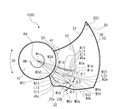
- FIG. 7 is a front view showing a schematic configuration of blades 20B of the axial fan 100B according to the third embodiment.
- the detailed configuration of the blade 20B will be described with reference to FIG. 7.
- the parts having the same configuration as the axial fan 100 and the axial fan 100A of FIGS. 1 to 6 are designated by the same reference numerals, and the description thereof will be omitted.
- the axial fan 100B according to the third embodiment specifies the direction of the cross-sectional portion S of the flow control unit 30B.
- the cross-sectional straight line W1 is a cross-sectional straight line W connecting the region inner edge portion 31 and the region outer edge portion 32 in the cross-section portion S1 of the flow control unit 30B at the position P1 in FIG.
- the intersection of the cross-sectional straight line W1 and the region inner edge portion 31 is defined as the inner peripheral side end portion W1a
- the intersection of the cross-sectional straight line W1 and the region outer edge portion 32 is defined as the outer peripheral side end portion W1b.
- the inner peripheral side end portion W1a is the inner peripheral side end portion of the cross-sectional straight line W1 in the radial direction
- the outer peripheral side end portion W1b is the outer peripheral side end portion of the cross-sectional straight line W1 in the radial direction.
- the outer peripheral side end portion W1b is located on the front edge portion 21 side with respect to the inner peripheral side end portion W1a, and the inner peripheral side end portion W1a is on the trailing edge portion 22 side with respect to the outer peripheral side end portion W1b. Is located in. That is, the flow control unit 30B is formed so that the outer peripheral side end portion W1b is located on the forward side of the axial flow fan 100B in the rotational direction DR with respect to the inner peripheral side end portion W1a.
- the straight line passing through the rotating shaft RA and the inner peripheral side end portion W1a is defined as the straight line M1a
- the straight line passing through the rotating shaft RA and the outer peripheral side end portion W1b is defined as the straight line M1b.
- the angle between the straight line M1a and the straight line M1b in the circumferential direction is defined as the angle ⁇ 1.
- the angle ⁇ 1 is two straight lines M1a and M1b connecting the inner peripheral side end portion W1a and the outer peripheral side end portion W1b in the cross-sectional portion S1 of the flow control unit 30B from the rotation axis RA which is the center of the axial flow fan 100B, respectively. The angle defined between.
- the cross-sectional straight line W2 is a cross-sectional straight line W connecting the region inner edge portion 31 and the region outer edge portion 32 in the cross-section portion S2 of the flow control unit 30B at the position P2 in FIG.
- the intersection of the cross-sectional straight line W2 and the region inner edge portion 31 is defined as the inner peripheral side end portion W2a
- the intersection of the cross-sectional straight line W2 and the region outer edge portion 32 is defined as the outer peripheral side end portion W2b.
- the inner peripheral side end portion W2a is the inner peripheral side end portion of the cross-sectional straight line W2 in the radial direction
- the outer peripheral side end portion W2b is the outer peripheral side end portion of the cross-sectional straight line W2 in the radial direction.
- the outer peripheral side end portion W2b is located on the front edge portion 21 side with respect to the inner peripheral side end portion W2a
- the inner peripheral side end portion W2a is on the trailing edge portion 22 side with respect to the outer peripheral side end portion W2b. Is located in. That is, the flow control unit 30B is formed so that the outer peripheral side end portion W2b is located on the forward side of the axial flow fan 100B in the rotational direction DR with respect to the inner peripheral side end portion W2a.
- the straight line passing through the rotating shaft RA and the inner peripheral side end portion W2a is defined as the straight line M2a
- the straight line passing through the rotating shaft RA and the outer peripheral side end portion W2b is defined as the straight line M2b.
- the angle between the straight line M2a and the straight line M2b in the circumferential direction is defined as the angle ⁇ 2.
- the angle ⁇ 2 is a straight line M2a and a straight line M2b connecting the inner peripheral side end portion W2a and the outer peripheral side end portion W2b in the cross-sectional portion S2 of the flow control unit 30B from the rotation axis RA which is the center of the axial flow fan 100B, respectively.
- the cross-sectional straight line W3 is a cross-sectional straight line W connecting the region inner edge portion 31 and the region outer edge portion 32 in the cross-section portion S3 of the flow control unit 30B at the position P3 in FIG.
- the intersection of the cross-sectional straight line W3 and the region inner edge portion 31 is defined as the inner peripheral side end portion W3a
- the intersection of the cross-sectional straight line W3 and the region outer edge portion 32 is defined as the outer peripheral side end portion W3b.
- the inner peripheral side end portion W3a is the inner peripheral side end portion of the cross-sectional straight line W3 in the radial direction
- the outer peripheral side end portion W3b is the outer peripheral side end portion of the cross-sectional straight line W3 in the radial direction.
- the outer peripheral side end portion W3b is located on the front edge portion 21 side with respect to the inner peripheral side end portion W3a
- the inner peripheral side end portion W3a is on the trailing edge portion 22 side with respect to the outer peripheral side end portion W3b. Is located in. That is, the flow control unit 30B is formed so that the outer peripheral side end portion W3b is located on the forward side of the axial flow fan 100B in the rotational direction DR with respect to the inner peripheral side end portion W3a.
- the straight line passing through the rotating shaft RA and the inner peripheral side end portion W3a is defined as the straight line M3a
- the straight line passing through the rotating shaft RA and the outer peripheral side end portion W3b is defined as the straight line M3b.
- the angle between the straight line M3a and the straight line M3b in the circumferential direction is defined as the angle ⁇ 3.
- the angle ⁇ 3 is a straight line M3a and a straight line M3b connecting the inner peripheral side end portion W3a and the outer peripheral side end portion W3b in the cross-sectional portion S3 of the flow control unit 30B from the rotation axis RA which is the center of the axial flow fan 100B, respectively.
- the inner peripheral side end portion W1a, the inner peripheral side end portion W2a, and the inner peripheral side end portion W3a are the first inner peripheral side end portions, and the outer peripheral side end portion W1b, the outer peripheral side end portion W2b, and the outer peripheral side end portion W3b are , The first outer peripheral side end.
- the straight line M1a, the straight line M2a and the straight line M3a are the first straight lines, and the straight lines M1b, the straight line M2b and the straight line M3b are the second straight lines.
- the angle between the first straight line and the second straight line is the angle ⁇ .
- the flow control unit 30B of the blade 20B is formed so that the angle ⁇ 2 is larger than the angle ⁇ 1 and the angle ⁇ 3 is larger than the angle ⁇ 2.
- the flow control unit 30B of the blade 20B is formed so as to satisfy the relationship of angle ⁇ 1 ⁇ angle ⁇ 2 ⁇ angle ⁇ 3 between the front edge portion 21 and the trailing edge portion 22.
- the angle ⁇ defined between the first straight line and the second straight line connecting the inner peripheral side end portion and the outer peripheral side end portion of the flow control unit 30B from the rotation axis RA, respectively, is the front edge portion 21. It is formed so that the trailing edge 22 side is larger than the side.
- the flow control unit 30B is similarly configured even when the cross-sectional portions S are set at four or more locations. That is, in the flow control unit 30B, the angle ⁇ defined between the first straight line and the second straight line connecting the rotation axis RA to the inner peripheral side end portion and the outer peripheral side end portion of the flow control unit 30B, respectively, is the front. It is formed so that the trailing edge 22 side is larger than the edge 21 side.
- the angle ⁇ defined between the first straight line and the second straight line connecting the rotation axis RA to the inner peripheral side end portion and the outer peripheral side end portion of the flow control unit 30B, respectively, is the front edge portion.
- the trailing edge 22 side is formed to be larger than the 21 side.
- the axial flow fan 100B is formed so that the surface surrounded by the cross-sectional portion S and the cross-sectional straight line W faces the inner peripheral side from the front edge portion 21 side to the trailing edge portion 22 side.
- the axial fan 100B can suppress the radial flow of the fluid toward the outer peripheral side of the flow control unit 30B, and can concentrate the fluid flow toward the outer peripheral side of the blade 20B on the flow control unit 30B. Then, the axial fan 100B can suppress the fluid from leaking from the blade surface on the positive pressure surface 25 side at the end portion on the outer peripheral side of the blade 20B, so that the growth of the blade end vortex can be suppressed. Therefore, the efficiency of the axial fan 100B can be improved, and the required power consumption of the axial fan 100B can be reduced.
- FIG. 8 is a front view showing a schematic configuration of blades 20C of the axial fan 100C according to the fourth embodiment.
- the detailed configuration of the blade 20C will be described with reference to FIG.
- the parts having the same configuration as the axial fan 100 to the axial fan 100B of FIGS. 1 to 7 are designated by the same reference numerals, and the description thereof will be omitted.
- the axial fan 100C according to the fourth embodiment specifies the direction of the cross section S of the flow control unit 30C, and the cross section S of the flow control unit 30C in the axial fan 100B according to the third embodiment is It faces in a different direction.
- the flow control unit 30C of the blade 20C is formed so that the angle ⁇ 2 is smaller than the angle ⁇ 1 and the angle ⁇ 3 is smaller than the angle ⁇ 2.
- the flow control unit 30C of the blade 20C is formed so as to satisfy the relationship of angle ⁇ 3 ⁇ angle ⁇ 2 ⁇ angle ⁇ 1 between the front edge portion 21 and the trailing edge portion 22.
- the angle ⁇ defined between the first straight line and the second straight line connecting the rotation axis RA to the inner peripheral side end portion and the outer peripheral side end portion of the flow control unit 30C, respectively, is the front edge portion 21. It is formed so that the trailing edge 22 side is smaller than the side.
- the flow control unit 30C is similarly configured even when the cross-sectional portions S are set at four or more locations. That is, in the flow control unit 30C, the angle ⁇ defined between the first straight line and the second straight line connecting the inner peripheral side end portion and the outer peripheral side end portion of the flow control unit 30C from the rotation axis RA is set to the front. It is formed so that the trailing edge 22 side is smaller than the edge 21 side.
- the angle ⁇ defined between the first straight line and the second straight line connecting the rotation axis RA to the inner peripheral side end portion and the outer peripheral side end portion of the flow control unit 30C, respectively, is the front edge portion.
- the trailing edge 22 side is formed to be smaller than the 21 side.
- the axial flow fan 100C is formed so that the surface surrounded by the cross-section portion S and the cross-section straight line W faces the rotation direction DR as the axial flow fan 100C is directed from the front edge portion 21 to the trailing edge portion 22.
- the axial flow fan 100C can suppress the flow of the radial component of the fluid toward the inner peripheral side or the outer peripheral side of the flow control unit 30C by the configuration, the fluid flow is concentrated on the cross section S of the flow control unit 30C. Can be done. Then, the axial fan 100C can suppress the fluid from leaking from the blade surface on the positive pressure surface 25 side at the end portion on the outer peripheral side of the blade 20C, so that the growth of the blade end vortex can be suppressed. Therefore, the efficiency of the axial fan 100C can be improved, and the required power consumption of the axial fan 100C can be reduced. Further, the axial fan 100C can make the distribution of the wind speed of the blown fluid more uniform in the radial direction, and can reduce the generated noise.
- FIG. 9 is a front view showing a schematic configuration of the blade 20D of the axial fan 100D according to the fifth embodiment.
- the detailed configuration of the blade 20D will be described with reference to FIG.
- the parts having the same configuration as the axial fan 100 to the axial fan 100C of FIGS. 1 to 8 are designated by the same reference numerals, and the description thereof will be omitted.
- the axial fan 100D according to the fifth embodiment specifies the configuration of the trailing edge portion 22 of the blade 20D.
- the trailing edge portion 22 has a protruding portion 22a formed on the rotation axis RA side of the wing 20, and an outer peripheral side trailing edge portion 22b formed on the outer peripheral edge portion 23 side of the wing 20 with respect to the protruding portion 22a. ..
- the protruding portion 22a is formed on the inner peripheral side of the blade 20 in the radial direction.
- the protruding portion 22a extends the trailing edge in the circumferential direction. That is, the protruding portion 22a projects and extends toward the backward side of the rotation direction DR of the blade 20D as compared with the outer peripheral side trailing edge portion 22b.
- the protruding portion 22a is formed in a flat plate shape, and is formed in a substantially triangular shape when viewed in a direction parallel to the axial direction of the rotating shaft RA.
- the protruding portion 22a is formed so as to be tapered with respect to the protruding direction.
- the shape of the protruding portion 22a is not limited to a substantially triangular shape.
- the shape of the protruding portion 22a may be formed into another shape such as a substantially trapezoidal shape or a shape having a plurality of substantially triangular shapes when viewed in a direction parallel to the axial direction of the rotating shaft RA. ..
- FIG. 10 is another front view showing a schematic configuration of the blade 20D of the axial fan 100D according to the fifth embodiment.
- the axial fan 100D may have a flow control unit 30D on the outer peripheral side in the radial direction of the blade 20D.
- the flow control unit 30D is composed of any one of the flow control unit 30, the flow control unit 30A, the flow control unit 30B, and the flow control unit 30C described above.
- the trailing edge portion 22 has a protruding portion 22a formed on the rotation axis RA side of the wing 20, and an outer peripheral side trailing edge portion 22b formed on the outer peripheral edge portion 23 side of the wing 20 with respect to the protruding portion 22a. ..
- the protruding portion 22a projects and extends to the backward side of the rotation direction DR of the blade 20D as compared with the outer peripheral side trailing edge portion 22b.
- the wind speed on the inner peripheral side in the radial direction can be increased from the maximum wind speed region by the protruding portion 22a forming the trailing edge portion 22 on the inner peripheral side.
- the axial fan 100D can make the distribution of the wind speed of the blown fluid more uniform in the radial direction, and can reduce the generated noise. Further, the axial fan 100D can make the wind speed of the fluid blown out in the entire radial direction uniform by combining with the flow control unit 30D formed on the outer peripheral side of the blade 20 in the radial direction.
- FIG. 11 is a conceptual diagram showing the meridional plane of the axial fan 100E according to the sixth embodiment.
- FIG. 12 is a front view showing a schematic configuration of the blade 20E of the axial fan 100E according to the sixth embodiment.
- FIG. 11 shows the shape of the axial fan 100E when rotationally projected onto the meridional surface including the rotary shaft RA and the blade 20E.
- the blade 20E when rotationally projected onto the meridional plane is indicated by the blade projection portion 20q
- the hub 10 when rotationally projected onto the meridional plane is indicated by the hub projection portion 10p.
- the detailed configuration of the blade 20E will be described with reference to FIGS. 11 and 12.
- the parts having the same configuration as the axial fan 100 to the axial fan 100D of FIGS. 1 to 10 are designated by the same reference numerals, and the description thereof will be omitted.
- the position Q1, the position Q2, and the position Q3 represented by the dotted lines represent the positions of the cross sections perpendicular to the rotation axis RA, respectively.
- the position Q1, the position Q2, and the position Q3 are located in the order of the position Q1, the position Q2, and the position Q3 from the upstream side to the downstream side in the direction in which the fluid flows in the axial direction AD of the rotating shaft RA.
- the portions located on the cross section represented by the position Q1 are portions located at the same position in the axial direction AD of the rotating shaft RA, respectively.
- the portions located on the cross section represented by the position Q2 are portions located at the same position in the axial direction AD of the rotation axis RA, respectively.
- the portions located on the cross section represented by the position Q3 are the portions located at the same position in the axial direction AD of the rotation axis RA, respectively.
- the relationship between the portion located on the cross section represented by the position Q1, the portion located on the cross section represented by the position Q2, and the portion located on the cross section represented by the position Q3 is the axis of the rotation axis RA, respectively. It is a part located at a different position in the direction AD.
- the positions Q1, position Q2, and position Q3 indicate the relative positional relationships between the front edge portion 21 and the trailing edge portion 22, respectively, of the position Q1, the position Q2, and the position Q3.
- the configuration of the three positions of the position Q1 to the position Q3 is described, but the relationship at the position Q1 to the position Q3 is not applied only to the three positions of the position Q1 to the position Q3. It also applies to relationships at four or more locations.
- the blade 20E has an inner peripheral side flow control unit 40.
- the inner peripheral side flow control unit 40 is a portion that controls the flow direction of the fluid flowing on the positive pressure surface 25 on the inner peripheral side of the blade 20E.
- the inner peripheral side flow control unit 40 is formed between the middle edge portion 29 and the trailing edge portion 22, which are at least intermediate positions between the front edge portion 21 and the trailing edge portion 22 in the circumferential direction CD. Further, the inner peripheral side flow control unit 40 is formed with a certain width so that at least a part thereof overlaps the forming region of the protruding portion 22a in the radial direction.
- the inner peripheral side flow control unit 40 is a region formed in an arc shape when viewed in a direction parallel to the rotation axis RA.
- the inner peripheral side flow control unit 40 has an inner peripheral side region inner edge portion 41 forming an inner peripheral side edge portion and an inner peripheral side region outer edge portion 42 forming an outer peripheral side edge portion.
- the inner peripheral edge portion 41 of the inner peripheral side region is located on the inner peripheral side of the virtual blade intermediate line 28 in the radial direction of the axial fan 100E.
- the outer peripheral edge portion 42 of the inner peripheral region region is located on the inner peripheral side of the virtual blade intermediate line 28 in the radial direction of the axial fan 100E.
- the outer peripheral edge portion 42 of the inner peripheral region may be located on the outer peripheral side of the virtual blade intermediate line 28 in the radial direction of the axial fan 100E.
- the inner edge portion 41 of the inner peripheral side region is formed in an arc shape, and is formed so that the distance from the rotation shaft RA is constant in the radial direction of the axial flow fan 100E.
- the outer peripheral edge portion 42 of the inner peripheral side region is formed in an arc shape, and is formed so that the distance from the rotation shaft RA is constant in the radial direction of the axial flow fan 100E.
- the inner peripheral side flow control unit 40 is a region formed between the inner peripheral side region inner edge portion 41 and the inner peripheral side region outer edge portion 42. Further, the inner peripheral side flow control unit 40 is formed along the circumferential direction CD of the axial fan 100E at least in a part between the front edge portion 21 and the trailing edge portion 22. That is, the inner peripheral side flow control unit 40 is formed so as to extend in the radial direction of the axial fan 100E and extend in the circumferential direction CD in the blade 20E.
- the inner peripheral side flow control unit 40 is formed to have a constant radial width at any position of the circumferential CD of the axial fan 100E. That is, in the inner peripheral side flow control unit 40, the distance between the inner peripheral side region inner edge portion 41 and the inner peripheral side region outer edge portion 42 in the radial direction is constant at any position of the circumferential direction CD of the axial flow fan 100E. Is formed in. However, the inner peripheral region inner edge 41 and the inner peripheral region outer edge 42 are limited to a configuration in which the distance from the rotation axis RA is constant in the radial direction of the axial fan 100E. is not it. In this case, the axial fan 100E is formed to have a width having a different radial width depending on the position of the circumferential CD of the axial fan 100E.
- the inner peripheral side flow control unit 40 is located relatively on the inner peripheral side in the radial direction of the blade 20E.
- the inner peripheral side virtual region intermediate line 43 of the inner peripheral side flow control unit 40 is the virtual blade intermediate line 28 between the outer peripheral edge portion 23 and the inner peripheral edge portion 24, that is, the intermediate position in the radial direction of the blade 20E. It is located on the inner peripheral side of the virtual wing intermediate line 28. It is desirable that the inner peripheral side flow control unit 40 is formed in a range equal to the region where the protruding portion 22a of the trailing edge portion 22 is formed in the radial direction.
- the inner peripheral side flow control unit 40 is not limited to a configuration in which the protrusion 22a of the trailing edge portion 22 is formed in the same range as the region formed in the radial direction.
- the inner peripheral flow control unit 40 may be formed in a range smaller than the region where the protruding portion 22a of the trailing edge portion 22 is formed in the radial direction, and the protruding portion 22a of the trailing edge portion 22 is formed. It may be formed in a range larger than the area where it is formed. At least a part of the inner peripheral side flow control unit 40 may be formed in a region where the protruding portion 22a of the trailing edge portion 22 is formed in the radial direction.
- the blade cross section in the radial direction is the rotational direction DR of the axial fan 100E.
- the wing plate is curved and warped so that it is convex in the opposite direction.
- the inner peripheral side flow control unit 40 is provided so that at least a part of the circumferential CD between the front edge portion 21 and the trailing edge portion 22 of the blade 20E is convex to the upstream side in the fluid flow direction.
- the board is curved and warped.
- the inner peripheral side flow control unit 40 is formed so that the positive pressure surface 25 side of the blade 20E is recessed in at least a part of the circumferential direction CD in the axial flow fan 100E, and the negative pressure surface of the blade 20E corresponding to the portion. It is formed so that the 26 side is convex.
- the inner peripheral side cross section SI shown by the dotted line in FIG. 12 shows the cross section of the blade 20E in the inner peripheral side flow control unit 40.
- the inner peripheral side cross section SI has a positive pressure surface 25 side recessed and a negative pressure surface 26 side convex as a cross section perpendicular to the rotation axis RA between the inner peripheral side region inner edge portion 41 and the inner peripheral side region outer edge portion 42. It is a curved part like this.
- the inner peripheral side cross-sectional portion SI shows a cross section of the inner peripheral side flow control unit 40 in a direction perpendicular to the rotation axis RA.
- the inner peripheral side cross-sectional portion SI is curved so as to be convex in the direction opposite to the rotation direction DR.
- the inner peripheral side cross-sectional portion SI is curved so as to be convex toward the upstream side in the direction AF in which the fluid flows.
- the inner peripheral side cross-sectional portion SI is curved so that the positive pressure surface 25 side is concave and the negative pressure surface 26 side is convex.
- the inner peripheral side end portion which is one end portion of the inner peripheral side cross-sectional portion SI, is the inner peripheral side region inner edge portion 41, and the other end portion of the cross-sectional portion S.
- the outer peripheral end, which is the end, is the inner peripheral region outer edge 42.
- the inner peripheral side cross-sectional portion SI1 shown by the dotted line in FIG. 12 shows the inner peripheral side cross-sectional portion SI of the blade 20E in the inner peripheral side flow control unit 40 at the position Q1 shown in FIG.
- the inner peripheral side cross-sectional portion SI2 shown by the dotted line in FIG. 12 shows the inner peripheral side cross-sectional portion SI of the blade 20E in the inner peripheral side flow control unit 40 at the position Q2 shown in FIG.
- the inner peripheral side cross-sectional portion SI3 shown by the dotted line in FIG. 12 shows the inner peripheral side cross-sectional portion SI of the blade 20E in the inner peripheral side flow control unit 40 at the position Q3 shown in FIG.
- the inner peripheral side cross section SI1 shows the cross section of the inner peripheral side flow control unit 40 in the direction perpendicular to the rotation axis RA at the position Q1 in the axial direction AD.
- the inner peripheral side cross-sectional portion SI2 shows the cross section of the inner peripheral side flow control unit 40 in the direction perpendicular to the rotation axis RA at the position Q2 in the axial direction AD.
- the inner peripheral side cross-sectional portion SI3 shows the cross section of the inner peripheral side flow control unit 40 in the direction perpendicular to the rotation axis RA at the position Q3 in the axial direction AD.
- the inner peripheral side end portion which is one end of the inner peripheral side cross-sectional portion SI1, the inner peripheral side cross-sectional portion SI2, and the inner peripheral side cross-sectional portion SI3, is the inner peripheral side region inner edge portion 41.
- the outer peripheral side end portion which is the other end portion of the inner peripheral side cross-sectional portion SI1, the inner peripheral side cross-sectional portion SI2, and the inner peripheral side cross-sectional portion SI3, is the inner peripheral side region outer edge portion 42.
- the inner peripheral side cross-sectional portion SI1, the inner peripheral side cross-sectional portion SI2, and the inner peripheral side cross-sectional portion SI3 are the inner peripheral side cross-sectional portions from the upstream side to the downstream side in the direction in which the fluid flows in the axial direction AD of the rotating shaft RA.
- the inner peripheral side cross-sectional portion SI is located in the order of SI1, the inner peripheral side cross-sectional portion SI2, and the inner peripheral side cross-sectional portion SI3.
- the inner peripheral side cross-sectional portion SI1, the inner peripheral side cross-sectional portion SI2, and the inner peripheral side cross-sectional portion SI3 are the inner peripheral side cross-sectional portions toward the trailing edge portion 22 from the front edge portion 21 in the circumferential direction CD of the axial flow fan 100E.
- the inner peripheral side cross-sectional portion SI is located in the order of SI1, the inner peripheral side cross-sectional portion SI2, and the inner peripheral side cross-sectional portion SI3.
- the inner peripheral side region inner edge portion 41 and the inner peripheral side region outer edge portion 42 are connected.
- the straight line be the inner peripheral side straight line WI.
- the inner peripheral side cross-sectional portion SI from the inner peripheral side straight line WI connecting the inner peripheral side region inner edge portion 41 and the inner peripheral side region outer edge portion 42 to the positive pressure surface 25 located at the farthest position in the normal direction.
- the distance of be the inner peripheral side protrusion amount LI.
- the inner peripheral side protrusion amount LI is the distance from the inner peripheral side straight line WI to the inner peripheral side deepest portion 45 at the position where the blade 20E is most convex in the normal direction in the inner peripheral side cross-sectional portion SI.
- the innermost deepest portion 45 is a portion in which the positive pressure surface 25 side is the most recessed in the inner peripheral side cross-sectional portion SI of the inner peripheral side flow control unit 40. That is, the innermost deepest portion 45 is a portion in the inner peripheral side cross-sectional portion SI of the inner peripheral side flow control unit 40 where the distance between the inner peripheral side straight line WI and the positive pressure surface 25 is the longest.
- the innermost deepest portion 45 is a portion of the inner peripheral side flow control unit 40 where the negative pressure surface 26 side protrudes most in the inner peripheral side cross-sectional portion SI, and has a convex shape constituting the inner peripheral side cross-sectional portion SI. It is the apex part of.
- the inner peripheral side region inner edge portion 41 and the inner peripheral side region outer edge portion 42 are separated.
- the connected straight line is defined as the inner peripheral side straight line WI1.
- the inner peripheral side straight line WI1 connecting the inner peripheral side region inner edge portion 41 and the inner peripheral side region outer edge portion 42 to the positive pressure surface 25 located at the farthest position in the normal direction. Let the distance be the inner peripheral side protrusion amount LI1.
- the inner peripheral side protrusion amount LI1 is the distance from the inner peripheral side straight line WI1 to the inner peripheral side deepest portion 45a at the position where the blade 20E is most convex in the normal direction in the inner peripheral side cross-sectional portion SI1.
- the innermost deepest portion 45a is a portion in which the positive pressure surface 25 side is the most recessed in the inner peripheral side cross-sectional portion SI1 of the inner peripheral side flow control unit 40. That is, the innermost deepest portion 45a is a portion of the inner peripheral side cross-sectional portion SI1 of the inner peripheral side flow control unit 40 where the distance between the inner peripheral side straight line WI1 and the positive pressure surface 25 is the longest.
- the innermost deepest portion 45a is a portion of the inner peripheral side cross-sectional portion SI1 of the inner peripheral side flow control unit 40 where the negative pressure surface 26 side is most protruding, and has a convex shape constituting the inner peripheral side cross-sectional portion SI1. It is the apex part of.
- the inner peripheral side region inner edge portion 41 and the inner peripheral side region outer edge portion 42 are separated.
- the connected straight line is defined as the inner peripheral side straight line WI2.
- the inner peripheral side protrusion amount LI2 is the distance from the inner peripheral side straight line WI2 to the inner peripheral side deepest portion 45b at the position where the blade 20E is most convex in the normal direction in the inner peripheral side cross-sectional portion SI2.
- the innermost deepest portion 45b is a portion in which the positive pressure surface 25 side is the most recessed in the inner peripheral side cross-sectional portion SI2 of the inner peripheral side flow control unit 40. That is, the innermost deepest portion 45b is a portion in the inner peripheral side cross-sectional portion SI2 of the inner peripheral side flow control unit 40 where the distance between the inner peripheral side straight line WI2 and the positive pressure surface 25 is the longest.
- the innermost deepest portion 45b is a portion of the inner peripheral side cross-sectional portion SI2 of the inner peripheral side flow control unit 40 where the negative pressure surface 26 side is most protruding, and has a convex shape constituting the inner peripheral side cross-sectional portion SI2. It is the apex part of.
- the inner peripheral side region inner edge portion 41 and the inner peripheral side region outer edge portion 42 are separated.
- the connected straight line is defined as the inner peripheral side straight line WI3.
- the inner peripheral side straight line WI3 connecting the inner peripheral side region inner edge portion 41 and the inner peripheral side region outer edge portion 42 to the positive pressure surface 25 located at the farthest position in the normal direction. Let the distance be the inner peripheral side protrusion amount LI3.
- the inner peripheral side protrusion amount LI3 is the distance from the inner peripheral side straight line WI3 to the inner peripheral side deepest portion 45c at the position where the blade 20E is most convex in the normal direction in the inner peripheral side cross-sectional portion SI3.
- the innermost deepest portion 45c is a portion in which the positive pressure surface 25 side is the most recessed in the inner peripheral side cross-sectional portion SI3 of the inner peripheral side flow control unit 40. That is, the innermost deepest portion 45c is a portion in the inner peripheral side cross-sectional portion SI3 of the inner peripheral side flow control unit 40 where the distance between the inner peripheral side straight line WI3 and the positive pressure surface 25 is the longest.
- the innermost deepest portion 45c is a portion of the inner peripheral side cross-sectional portion SI3 of the inner peripheral side flow control unit 40 where the negative pressure surface 26 side is most protruding, and has a convex shape constituting the inner peripheral side cross-sectional portion SI3. It is the apex part of.
- the inner peripheral side flow control unit 40 of the wing 20E is formed so that the inner peripheral side protrusion amount LI decreases from the front edge portion 21 to the trailing edge portion 22 between the front edge portion 21 and the trailing edge portion 22.
- the curvature of the blade 20E toward the upstream side becomes smaller from the front edge portion 21 toward the trailing edge portion 22 between the front edge portion 21 and the trailing edge portion 22. It is formed to be.
- the inner peripheral flow control unit 40 of the blade 20E is formed so that the depth of the recess on the positive pressure surface 25 side decreases from the front edge portion 21 to the trailing edge portion 22.
- the region where the inner peripheral side protrusion amount LI becomes smaller is at least the middle abdomen 29 and the trailing edge portion of the wing 20E. It exists in the area between 22 and 22.
- the middle abdomen 29 of the wing 20E is an intermediate position between the front edge 21 and the trailing edge 22 in the axial direction of the rotation axis RA.
- the inner peripheral side flow control unit 40 of the blade 20E is formed so that the inner peripheral side protrusion amount LI2 is smaller than the inner peripheral side protrusion amount LI1 and is smaller than the inner peripheral side protrusion amount LI2. Is also formed so that the amount of protrusion LI3 on the inner peripheral side is small.
- the inner peripheral flow control unit 40 of the blade 20E satisfies the relationship of the inner peripheral side protrusion amount LI3 ⁇ inner peripheral side protrusion amount LI2 ⁇ inner peripheral side protrusion amount LI1 between the front edge portion 21 and the trailing edge portion 22. It is formed like this.
- the inner peripheral side flow control unit 40 is on the trailing edge portion 22 side of the inner peripheral side protrusion amount LI on the front edge portion 21 side in the circumferential direction CD. It is formed so that the amount of protrusion LI on the inner peripheral side of the above is small.
- the inner peripheral side flow control unit 40 of the wing 20E is formed so that the inner peripheral side protrusion amount LI decreases from the front edge portion 21 to the trailing edge portion 22 between the front edge portion 21 and the trailing edge portion 22. It is not limited to the configuration that is used.
- the inner peripheral side flow control unit 40 of the blade 20E does not have to increase the inner peripheral side protrusion amount LI from the front edge portion 21 to the trailing edge portion 22 between the front edge portion 21 and the trailing edge portion 22. , There may be a region where the inner peripheral side protrusion amount LI is equal from the front edge portion 21 toward the trailing edge portion 22.
- the regions having the same inner peripheral side protrusion amount LI may be a partial region or all regions from the front edge portion 21 to the trailing edge portion 22. Further, in the inner peripheral side flow control unit 40 of the wing 20E, when there is a region where the inner peripheral side protrusion amount LI is equal, the region where the inner peripheral side protrusion amount LI is equal is at least the middle abdomen 29 and the trailing edge portion of the wing 20E. It exists in the area between 22 and 22.
- the wing 20E has the same inner peripheral side protrusion amount LI from the middle abdomen 29 to the trailing edge 22 of the wing 20E between at least the front edge 21 and the trailing edge, or at least the rear of the wing 20E from the middle 29. It has a region where the inner peripheral side protrusion amount LI becomes smaller toward the edge portion 22. That is, the wing 20E has a region in which the protrusion amount LI on the inner peripheral side does not change from the front edge 21 side toward the trailing edge 22 side, or the inner peripheral side as it goes from the front edge 21 side to the trailing edge 22 side. It is formed so as to have a region where the protrusion amount LI becomes small.
- FIG. 13 is a front view showing a schematic configuration of the blade 20F of the axial fan 100F according to the sixth embodiment of the modified example.
- the axial fan 100F has an inner peripheral side flow control unit 40 on the inner peripheral side of the blade 20F and a flow control unit 30 on the outer peripheral side of the blade 20F.
- the flow control unit 30 may be any one of the flow control unit 30A to the flow control unit 30D.
- the positions Q1, the position Q2, and the position Q3 shown in FIG. 2 have relative positional relationships between the front edge portion 21 and the trailing edge portion 22, respectively, of the position Q1, the position Q2, and the position Q3. It is shown.
- the positions Q1, position Q2, and position Q3 of the inner peripheral side cross-sectional portion SI in the inner peripheral side flow control unit 40 shown in FIG. 13 are the same positions as the positions P1, position P2, and position P3 of the cross-sectional portion S in the flow control unit 30. It may be in a different position.
- the wing 20E has a region in which the inner peripheral side protrusion amount LI does not change from the front edge 21 side to the trailing edge 22 side, or an inner peripheral side protrusion amount from the front edge 21 side toward the trailing edge 22 side. It is formed so as to have a region where the LI becomes small. Therefore, in the radial direction, the axial flow fan 100E controls the inner peripheral side flow from the outer peripheral side outside the blade 20E, which works more efficiently than the inner peripheral side flow control unit 40 formed on the inner peripheral side of the blade 20E. The wind speed on the inner peripheral side can be increased while avoiding the attraction of the fluid flow to the portion 40. Therefore, the axial fan 100E can make the distribution of the wind speed of the blown airflow FL more uniform and reduce the generated noise without requiring an increase in the power consumption required for the axial fan 100E.
- the amount of protrusion on the inner peripheral side does not change from the front edge 21 side toward the trailing edge 22, or the amount of protrusion on the inner peripheral side from the front edge 21 side toward the trailing edge 22. It is formed so as to have a region where the LI becomes small. Therefore, in the radial direction, the axial flow fan 100F controls the inner peripheral side flow from the outer peripheral side outside the blade 20F, which works more efficiently than the inner peripheral side flow control unit 40 formed on the inner peripheral side of the blade 20F. The wind speed on the inner peripheral side can be increased while avoiding the attraction of the fluid flow to the portion 40. Therefore, the axial fan 100F can make the distribution of the wind speed of the blown airflow FL more uniform and reduce the generated noise without requiring an increase in the power consumption required for the axial fan 100F.
- the virtual region intermediate line 33 which is an intermediate position between the region inner edge portion 31 and the region outer edge portion 32, is the wing 20. It is located on the outer peripheral side of the virtual wing intermediate line 28, which is an intermediate position between the inner peripheral edge portion 24 and the outer peripheral edge portion 23 of the above.
- the axial fan 100F has a cross-sectional portion S on the outer peripheral side of the blade 20F that is convex from the downstream side to the upstream side in the flow direction of the fluid formed by the blade 20. Therefore, as shown in the fluid flow MF of FIG.
- the fluid can be attracted from the inner peripheral side of the cross-sectional portion S to the cross-sectional portion S on the outer peripheral side where the work is performed with high efficiency. Therefore, the axial fan 100F can reduce the power consumption required for the axial fan 100F. Further, in the axial flow fan 100F, since the protrusion amount L of the cross-sectional portion S increases from the front edge portion 21 side to the trailing edge portion 22 side in the fluid flow direction, the positive pressure surface 25 side is along the cross section S. The fluid easily flows, and the flow of the fluid on the positive pressure surface 25 side is concentrated on the cross section S. Therefore, the axial flow fan 100F can suppress the leakage of fluid from the blade surface on the positive pressure surface 25 side at the outer peripheral end of the blade 20F, and can suppress the growth of the blade tip vortex.
- FIG. 14 is a front view showing a schematic configuration of the blade 20G of the axial fan 100G according to the seventh embodiment.
- the detailed configuration of the blade 20G will be described with reference to FIG.
- the parts having the same configuration as the axial fan 100 to the axial fan 100F of FIGS. 1 to 13 are designated by the same reference numerals, and the description thereof will be omitted.
- the flow control unit 30 is not shown in FIG. 14, the axial fan 100G is located on the outer peripheral side of the axial fan 100G as in the axial fan 100F according to the sixth embodiment shown in FIG. It may have a flow control unit 30.
- the flow control unit 30 may be any one of the flow control unit 30 and the flow control unit 30D.
- the blade 20G has an inner peripheral side flow control unit 40G.
- the inner peripheral side flow control unit 40G is a portion that controls the flow direction of the fluid flowing along the positive pressure surface 25 on the inner peripheral side of the blade 20G.
- the inner peripheral side flow control unit 40G is a region formed in an arc shape when viewed in a direction parallel to the rotation axis RA.
- the inner peripheral side flow control unit 40G has an inner peripheral side region inner edge portion 41 forming an inner peripheral side edge portion and an inner peripheral side region outer edge portion 42 forming an outer peripheral side edge portion.
- At least a part of the inner peripheral side flow control unit 40G is formed in a region where the protruding portion 22a of the trailing edge portion 22 is formed in the radial direction. It is desirable that the inner peripheral side flow control unit 40G is formed in a region equal to the region where the protruding portion 22a of the trailing edge portion 22 is formed in the radial direction.
- the inner peripheral side flow control unit 40G is different from the inner peripheral side flow control unit 40 in the configuration of forming the inner peripheral side protrusion amount LI.
- the inner peripheral side flow control unit 40G of the wing 20G is formed so that the inner peripheral side protrusion amount LI increases from the front edge portion 21 to the trailing edge portion 22 between the front edge portion 21 and the trailing edge portion 22.
- the curvature of the blade 20G toward the upstream side increases from the front edge portion 21 toward the trailing edge portion 22 between the front edge portion 21 and the trailing edge portion 22. It is formed to be.
- the inner peripheral flow control unit 40G of the blade 20G has a positive pressure surface 25 with respect to the region of the outer portion of the inner peripheral flow control unit 40G in the radial direction as it goes from the front edge portion 21 to the trailing edge portion 22.
- the region where the inner peripheral side protrusion amount LI is large exists at least in the region between the middle abdomen 29 and the trailing edge 22 of the wing 20G.
- the inner peripheral side flow control unit 40G of the blade 20G is formed so that the inner peripheral side protrusion amount LI2 is larger than the inner peripheral side protrusion amount LI1 and is larger than the inner peripheral side protrusion amount LI2. Is also formed so that the amount of protrusion LI3 on the inner peripheral side is large.
- the inner peripheral flow control unit 40G of the blade 20G satisfies the relationship of the inner peripheral side protrusion amount LI1 ⁇ inner peripheral side protrusion amount LI2 ⁇ inner peripheral side protrusion amount LI3 between the front edge portion 21 and the trailing edge portion 22. It is formed like this.
- the inner peripheral side flow control unit 40G has a trailing edge portion 22 side of the inner peripheral side protrusion amount LI on the front edge portion 21 side in the circumferential direction CD even when the inner peripheral side cross-sectional portion SI is set to four or more points. It is formed so that the amount of protrusion LI on the inner peripheral side of the above is large.
- FIG. 15 is a conceptual diagram for explaining the configuration of the outdoor unit 50L including the axial fan 100G according to the seventh embodiment.
- the outdoor unit 50L has a heat exchanger 68, a compressor 64, and an axial fan 100G.
- the inside of the outdoor unit 50L is divided into a blower chamber 56 in which a heat exchanger 68 and an axial fan 100G are installed and a machine room 57 in which a compressor 64 is installed by a partition plate 51g which is a wall body.
- the axial fan 100G is connected to the fan motor 61, and the fan motor 61 is attached to the motor support portion 69.
- the outdoor unit 50L by designing the heat exchanger 68 to have a high pressure loss, the contribution of work on the outer peripheral side of the axial fan 100G is increased, so that the inflow of fluid to the inner peripheral side of the axial fan 100G is hindered. In that case, the inflow of the fluid on the inner peripheral side of the axial fan 100G may decrease. Further, the outdoor unit 50L has a shaft when the inflow of fluid to the inner peripheral side of the axial fan 100G is obstructed by a structure such as a motor support portion 69 arranged on the upstream side of the axial fan 100G. There is a risk that the inflow of fluid on the inner peripheral side of the flow fan 100G will decrease. In FIG.
- the flow FL2 represents an example of the flow of the fluid affected by the motor support portion 69.
- the outdoor unit 50L has a shaft due to a decrease in the inflow of fluid on the inner peripheral side of the axial fan 100G. A large load may be generated on the flow fan 100G, and the power consumption may increase.
- the inner peripheral side flow control unit 40G of the wing 20G is formed so that the inner peripheral side protrusion amount LI increases from the front edge portion 21 to the trailing edge portion 22 between the front edge portion 21 and the trailing edge portion 22.
- the axial fan 100G has an inner peripheral side flow control unit 40G, the fluid flow F3 can be attracted from the outer peripheral side of the blade 20G to the inner peripheral side of the blade 20G, and the efficiency of the axial fan 100G is improved. Can be planned.
- the inner peripheral side flow control unit 40G is formed so that the inner peripheral side protrusion amount LI increases from the front edge portion 21 toward the trailing edge portion 22.
- the inner peripheral side flow control unit 40G can effectively work on the front edge portion 21 side in the outer peripheral side region of the inner peripheral side flow control unit 40G, and then gradually attract the fluid flow to the inner peripheral side. ..
- the axial flow fan 100G can secure the amount of work in the region on the outer peripheral side of the flow control unit 40G on the inner peripheral side, and can reduce the load on the inner peripheral side by increasing the inflow on the inner peripheral side. Therefore, the axial fan 100G can improve the efficiency of the axial fan 100G and reduce the required power consumption. Further, the axial fan 100G can make the distribution of the wind speed of the blown airflow FL more uniform, and can reduce the generated noise.
- FIG. 16 is a front view showing a schematic configuration of blades 20H of the axial fan 100H according to the eighth embodiment.
- the detailed configuration of the blade 20H will be described with reference to FIG.
- the parts having the same configuration as the axial fan 100 to the axial fan 100G of FIGS. 1 to 15 are designated by the same reference numerals, and the description thereof will be omitted.
- the axial fan 100H according to the eighth embodiment specifies the position of the innermost deepest portion 45 of the inner peripheral side flow control unit 40H.
- the flow control unit 30 is not shown in FIG. 16, the axial fan 100H is located on the outer peripheral side of the axial fan 100H as in the axial fan 100F according to the sixth embodiment shown in FIG. It may have a flow control unit 30.
- the flow control unit 30 may be any one of the flow control unit 30 to the flow control unit 30D.
- the innermost deepest portion 45 is the portion where the positive pressure surface 25 side is the most recessed in the inner peripheral side cross-sectional portion SI of the inner peripheral side flow control unit 40. Further, the deepest portion 45 on the inner peripheral side is a portion in which the negative pressure surface 26 side protrudes most in the inner peripheral side cross-sectional portion SI of the inner peripheral side flow control unit 40, and is a convex apex constituting the inner peripheral side cross-sectional portion SI. It is a part.
- the innermost deepest portion 45a is the innermost deepest portion 45 of the inner peripheral side cross-sectional portion SI1 in the inner peripheral side flow control unit 40H.
- the innermost deepest portion 45b is the innermost deepest portion 45 of the inner peripheral side cross-sectional portion SI2 in the inner peripheral side flow control unit 40H.
- the innermost deepest portion 45c is the innermost deepest portion 45 of the inner peripheral side cross-sectional portion SI3 in the inner peripheral side flow control unit 40H.
- the inner peripheral side cross-sectional portion SI1, the inner peripheral side cross-sectional portion SI2, and the inner peripheral side cross-sectional portion SI3 are the inner peripheral side cross-sectional portions from the front edge portion 21 to the trailing edge portion 22 in the circumferential direction CD of the axial flow fan 100H.
- the inner peripheral side cross-sectional portion SI is located in the order of SI1, the inner peripheral side cross-sectional portion SI2, and the inner peripheral side cross-sectional portion SI3.
- the distance RI1 shown in FIG. 16 is the distance between the rotating shaft RA and the deepest portion 45a on the inner peripheral side in the radial direction of the axial fan 100H.
- the distance RI2 is the distance between the rotary shaft RA and the innermost deepest portion 45b in the radial direction of the axial fan 100H.
- the distance RI3 is the distance between the rotating shaft RA and the innermost deepest portion 45c in the radial direction of the axial fan 100H.
- the inner peripheral side flow control unit 40H of the axial fan 100H is formed so that the distance RI2 is smaller than the distance RI1 and the distance RI3 is smaller than the distance RI2.
- the axial fan 100H is formed so that the distance RI3 ⁇ distance RI2 ⁇ distance RI1.
- the inner peripheral side flow control unit 40H of the axial flow fan 100H is formed so that the position of the inner peripheral side deepest portion 45 approaches the rotation axis RA in the radial direction from the front edge portion 21 to the trailing edge portion 22 in the circumferential direction.
- the inner peripheral side flow control unit 40H is formed so that the innermost deepest portion 45 is located from the outer peripheral side to the inner peripheral side in the radial direction from the front edge portion 21 to the trailing edge portion 22 in the circumferential direction CD.
- the inner peripheral flow control unit 40H of the axial flow fan 100H is such that the innermost deepest portion 45 is located from the outer peripheral side to the inner peripheral side in the radial direction as it goes from the front edge portion 21 to the trailing edge portion 22 in the circumferential direction. Is formed in.
- the flow of the fluid flowing along the positive pressure surface 25 of the blade 20 with the rotation of the axial fan 100 is most concentrated on the innermost deepest portion 45 of the inner peripheral side cross-sectional portion SI on the positive pressure surface 25 of the blade 20.
- the axial fan 100H moves toward the inner peripheral side of the axial fan 100H by locating the deepest portion 45 on the inner peripheral side toward the inner peripheral side in the radial direction as it goes from the front edge portion 21 to the trailing edge portion 22. It can induce the flow of fluid. As a result, the axial flow fan 100H can be made more efficient by increasing the inflow of fluid to the inner peripheral side, and the required power consumption can be reduced. Further, the axial fan 100H can make the distribution of the wind speed of the blown fluid more uniform in the radial direction, and can reduce the generated noise.
- FIG. 17 is a front view showing a schematic configuration of the blade 20I of the axial fan 100I according to the ninth embodiment.
- the detailed configuration of the blade 20I will be described with reference to FIG.
- the parts having the same configuration as the axial fan 100 to the axial fan 100G of FIGS. 1 to 16 are designated by the same reference numerals, and the description thereof will be omitted.
- the axial fan 100I according to the ninth embodiment specifies the direction of the inner peripheral side cross-sectional portion SI of the inner peripheral side flow control unit 40I.
- the inner peripheral side straight line WI1 is an inner circumference connecting the inner peripheral side region inner edge portion 41 and the inner peripheral side region outer edge portion 42 in the inner peripheral side cross-sectional portion SI1 of the inner peripheral side flow control unit 40I at the position Q1 in FIG. It is a side straight line WI.
- the intersection of the inner peripheral straight line WI1 and the inner peripheral region inner edge 41 is defined as the inner peripheral end W1d
- the intersection of the inner peripheral straight line WI1 and the inner peripheral region outer edge 42 is the outer peripheral end. It is defined as part W1e.
- the inner peripheral side end portion W1d is the inner peripheral side end portion of the inner peripheral side straight line WI1 in the radial direction
- the outer peripheral side end portion W1e is the outer peripheral side end portion of the inner peripheral side straight line WI1 in the radial direction.
- the outer peripheral side end portion W1e is located on the front edge portion 21 side with respect to the inner peripheral side end portion W1d
- the inner peripheral side end portion W1d is on the trailing edge portion 22 side with respect to the outer peripheral side end portion W1e. Is located in. That is, the inner peripheral side flow control unit 40I is formed so that the outer peripheral side end portion W1e is located on the forward side of the axial flow fan 100I in the rotational direction DR with respect to the inner peripheral side end portion W1d.
- the straight line passing through the rotating shaft RA and the inner peripheral side end portion W1d is defined as the straight line M1d
- the straight line passing through the rotating shaft RA and the outer peripheral side end portion W1e is defined as the straight line M1e.
- the angle between the straight line M1d and the straight line M1e in the circumferential direction is defined as the angle ⁇ 1.
- the angle ⁇ 1 is a straight line M1d connecting the rotation axis RA, which is the center of the axial flow fan 100I, with the inner peripheral side end portion W1d and the outer peripheral side end portion W1e in the inner peripheral side cross-sectional portion SI1 of the inner peripheral side flow control unit 40I, respectively.
- the angle defined between the two straight lines of the straight line M1e is a straight line M1d connecting the rotation axis RA, which is the center of the axial flow fan 100I, with the inner peripheral side end portion W1d and the outer peripheral side end portion W1e in the inner peripheral side cross-sectional portion SI1
- the inner peripheral side straight line WI2 connects the inner peripheral side region inner edge portion 41 and the inner peripheral side region outer edge portion 42 in the inner peripheral side cross-sectional portion SI2 of the inner peripheral side flow control unit 40I at the position Q2 in FIG. It is a straight line WI on the inner peripheral side.
- the intersection of the inner peripheral straight line WI2 and the inner peripheral region inner edge 41 is defined as the inner peripheral end W2d
- the intersection of the inner peripheral straight line WI2 and the inner peripheral region outer edge 42 is the outer peripheral end. It is defined as part W2e.
- the inner peripheral side end portion W2d is the inner peripheral side end portion of the inner peripheral side straight line WI2 in the radial direction
- the outer peripheral side end portion W2e is the outer peripheral side end portion of the inner peripheral side straight line WI2 in the radial direction.
- the outer peripheral side end portion W2e is located on the front edge portion 21 side with respect to the inner peripheral side end portion W2d
- the inner peripheral side end portion W2d is on the trailing edge portion 22 side with respect to the outer peripheral side end portion W2e. Is located in. That is, the inner peripheral side flow control unit 40I is formed so that the outer peripheral side end portion W2e is located on the forward side of the axial flow fan 100I in the rotational direction DR with respect to the inner peripheral side end portion W2d.
- the straight line passing through the rotating shaft RA and the inner peripheral side end portion W2d is defined as the straight line M2d
- the straight line passing through the rotating shaft RA and the outer peripheral side end portion W2e is defined as the straight line M2e.
- the angle between the straight line M2d and the straight line M2e in the circumferential direction is defined as the angle ⁇ 2.
- the angle ⁇ 2 is a straight line M2d connecting the rotation axis RA, which is the center of the axial flow fan 100I, with the inner peripheral side end portion W2d and the outer peripheral side end portion W2e in the inner peripheral side cross-sectional portion SI2 of the inner peripheral side flow control unit 40I, respectively.
- the angle defined between the two straight lines of the straight line M2e is a straight line M2d connecting the rotation axis RA, which is the center of the axial flow fan 100I, with the inner peripheral side end portion W2d and the outer peripheral side end portion W2e in the inner peripheral side cross-sectional portion SI2
- the inner peripheral side straight line WI3 connects the inner peripheral side region inner edge portion 41 and the inner peripheral side region outer edge portion 42 in the inner peripheral side cross-sectional portion SI3 of the inner peripheral side flow control unit 40I at the position Q3 in FIG. It is a straight line WI on the inner peripheral side.
- the intersection of the inner peripheral straight line WI3 and the inner peripheral region inner edge 41 is defined as the inner peripheral end W3d
- the intersection of the inner peripheral straight line WI3 and the inner peripheral region outer edge 42 is the outer peripheral end. It is defined as part W3e.
- the inner peripheral side end portion W3d is the inner peripheral side end portion of the inner peripheral side straight line WI3 in the radial direction
- the outer peripheral side end portion W3e is the outer peripheral side end portion of the inner peripheral side straight line WI3 in the radial direction.
- the outer peripheral side end portion W3e is located on the front edge portion 21 side with respect to the inner peripheral side end portion W3d
- the inner peripheral side end portion W3d is on the trailing edge portion 22 side with respect to the outer peripheral side end portion W3e. Is located in. That is, the inner peripheral side flow control unit 40I is formed so that the outer peripheral side end portion W3e is located on the forward side of the axial flow fan 100I in the rotational direction DR with respect to the inner peripheral side end portion W3d.
- the straight line passing through the rotating shaft RA and the inner peripheral side end portion W3d is defined as the straight line M3d
- the straight line passing through the rotating shaft RA and the outer peripheral side end portion W3e is defined as the straight line M3e.
- the angle between the straight line M3d and the straight line M3e in the circumferential direction is defined as the angle ⁇ 3.
- the angle ⁇ 3 is a straight line M3d connecting the rotation axis RA, which is the center of the axial flow fan 100I, with the inner peripheral side end portion W3d and the outer peripheral side end portion W3e in the inner peripheral side cross-sectional portion SI3 of the inner peripheral side flow control unit 40I, respectively.
- the angle defined between the two straight lines of the straight line M3e is a straight line M3d connecting the rotation axis RA, which is the center of the axial flow fan 100I, with the inner peripheral side end portion W3d and the outer peripheral side end portion W3e in the inner peripheral side cross-sectional portion SI3
- the inner peripheral side end portion W1d, the inner peripheral side end portion W2d, and the inner peripheral side end portion W3d are the second inner peripheral side end portions, and the outer peripheral side end portion W1e, the outer peripheral side end portion W2e, and the outer peripheral side end portion W3e are , The second outer peripheral side end.
- the straight line M1d, the straight line M2d and the straight line M3d are the first straight lines on the inner peripheral side, and the straight lines M1e, the straight line M2e and the straight line M3e are the second straight lines on the inner peripheral side.
- the angle between the inner peripheral side first straight line and the inner peripheral side second straight line is the angle ⁇ .
- the inner peripheral side flow control unit 40I of the blade 20I is formed so that the angle ⁇ 2 is larger than the angle ⁇ 1 and the angle ⁇ 3 is larger than the angle ⁇ 2.
- the inner peripheral flow control unit 40I of the blade 20I is formed so as to satisfy the relationship of angle ⁇ 1 ⁇ angle ⁇ 2 ⁇ angle ⁇ 3 between the front edge portion 21 and the trailing edge portion 22.
- it is defined between the inner peripheral side first straight line and the inner peripheral side second straight line connecting the inner peripheral side end portion and the outer peripheral side end portion of the inner peripheral side flow control unit 40I from the rotation axis RA, respectively.
- the angle ⁇ is formed so as to be larger on the trailing edge 22 side than on the front edge 21 side.
- the inner peripheral side flow control unit 40I has the same relationship of angles ⁇ in the circumferential direction even when the inner peripheral side cross-sectional portion SI is set to four or more points. That is, the angle ⁇ defined between the inner peripheral side first straight line and the inner peripheral side second straight line connecting the inner peripheral side end portion and the outer peripheral side end portion of the inner peripheral side flow control unit 40I from the rotation axis RA, respectively. Is formed so that the trailing edge 22 side is larger than the front edge 21 side.
- the inner peripheral side flow control unit 40I is composed of an inner peripheral side first straight line and an inner peripheral side second straight line connecting the rotation shaft RA to the inner peripheral side end portion and the outer peripheral side end portion of the inner peripheral side flow control unit 40I, respectively.
- the angle ⁇ defined between the two is formed so as to be larger on the trailing edge 22 side than on the front edge 21 side.
- the axial fan 100I is formed so that the surface surrounded by the inner peripheral side cross-sectional portion SI and the inner peripheral side straight line WI faces the inner peripheral side as it goes from the front edge portion 21 to the trailing edge portion 22. ing.
- the axial flow fan 100I can attract the flow of the fluid to the inner peripheral side, the efficiency can be improved by increasing the inflow of the fluid to the inner peripheral side, and the required power consumption can be reduced. Further, the axial fan 100I can make the distribution of the wind speed of the blown fluid more uniform in the radial direction, and can reduce the generated noise.
- FIG. 18 is a conceptual diagram of the outdoor unit 50 provided with the axial fan 100J according to the tenth embodiment as viewed from the upper surface side. A detailed configuration of the blade 20J of the axial fan 100J will be described with reference to FIG. The parts having the same configuration as the axial fan 100 and the like shown in FIGS. 1 to 17 are designated by the same reference numerals, and the description thereof will be omitted.
- the axial fan 100J according to the tenth embodiment further specifies the configuration of the trailing edge portion 22. As shown in FIG. 18, when the axial fan 100J operates, the fluid F flows from the upstream UA of the axial fan 100J toward the downstream DA in the blower chamber 56.
- the axial fan 100J has a flow control unit 30.
- the flow control unit 30D is composed of any one of the flow control unit 30, the flow control unit 30A, the flow control unit 30B, and the flow control unit 30C described above.
- the trailing edge portion 22 of the blade 20J is located so that the outer peripheral side in the radial direction is located on the downstream side in the direction of the fluid flowing by the rotation of the blade 20J rather than the inner peripheral side in the radial direction. It is formed. More specifically, the outer peripheral side end portion 22g of the trailing edge portion 22 is located downstream of the inner peripheral side end portion 22f of the trailing edge portion 22 in the direction of the fluid flowing by the rotation of the blade 20J.
- the outer peripheral side end portion 22g is an outer peripheral side end portion in the radial direction of the trailing edge portion 22, and is a trailing edge portion 22 of the outer peripheral edge portion 23.
- the inner peripheral side end portion 22f is an end portion on the inner peripheral side in the radial direction in the trailing edge portion 22, and is a trailing edge portion 22 in the inner peripheral edge portion 24.
- the axial flow fan 100J is formed so that the outer peripheral side in the radial direction is located on the downstream side with respect to the direction of the fluid flowing by the rotation of the blade 20J, rather than the inner peripheral side in the radial direction. Therefore, the axial fan 100J can attract the fluid flow FL4 from the inner peripheral side of the blade 20J to the flow control unit 30 located on the outer peripheral side where the work is performed with high efficiency. Therefore, the axial fan 100J can reduce the required power consumption. Further, the axial fan 100J can make the distribution of the wind speed of the blown fluid more uniform in the radial direction, and can reduce the generated noise.
- FIG. 19 is a conceptual diagram of the outdoor unit 50 provided with the axial fan 100K according to the eleventh embodiment as viewed from the upper surface side.
- the detailed configuration of the blade 20K of the axial fan 100K will be described with reference to FIG.
- the parts having the same configuration as the axial fan 100 and the like shown in FIGS. 1 to 18 are designated by the same reference numerals, and the description thereof will be omitted.
- the axial fan 100K according to the eleventh embodiment further specifies the forming position in the flow control unit 30. As shown in FIG. 19, when the axial fan 100K is operated, the fluid F flows from the upstream UA of the axial fan 100J toward the downstream DA in the blower chamber 56.
- the axial fan 100K has a flow control unit 30.
- the flow control unit 30D is composed of any one of the flow control unit 30, the flow control unit 30A, the flow control unit 30B, and the flow control unit 30C described above.
- the flow control unit 30 of the wing 20K is formed between the middle abdomen 29 and the trailing edge 22. More specifically, in a cross section perpendicular to the rotation axis RA, a cross section S curved so that the positive pressure surface 25 side is concave and the negative pressure surface 26 side is convex is formed between the middle abdomen 29 and the trailing edge 22. It is formed. As described above, the middle abdomen 29 is an intermediate position between the front edge 21 and the trailing edge 22 in the axial direction of the rotation axis RA.
- the flow control unit 30 of the wing 20K is formed so that the protrusion amount L shown in FIG. 3 increases from the middle abdomen 29 to the trailing edge 22 between the middle abdomen 29 and the trailing edge 22. That is, the flow control unit 30 of the wing 20K is formed so that the curvature of the wing 20 toward the upstream side increases from the middle abdomen 29 to the trailing edge 22 between the middle abdomen 29 and the trailing edge 22. ing. In other words, in the flow control unit 30 of the wing 20K, the depth of the recess on the positive pressure surface 25 side increases from the middle abdomen 29 to the trailing edge 22 between the middle abdomen 29 and the trailing edge 22. It is formed like this.
- the flow control unit 30 of the blade 20K is formed so that the protrusion amount L2 is larger than the protrusion amount L1 and the protrusion amount L3 is larger than the protrusion amount L2.
- the flow control unit 30 of the wing 20K is formed so as to satisfy the relationship of protrusion amount L1 ⁇ protrusion amount L2 ⁇ projection amount L3 between the middle abdomen portion 29 and the trailing edge portion 22.
- the axial fan 100K is arranged so that the upstream side of the axial fan 100K is open in the radial direction and the downstream side of the axial fan 100K is a semi-open type surrounded by the bell mouth 63 in the radial direction. Has been done. Since the downstream side of the axial flow fan 100K is surrounded by the bell mouth 63, there is little flow of fluid leaking at the outer peripheral edge portion 23 of the blade 20.
- the axial fan 100K can further exert the effect of suppressing the flow of the fluid leaking by the flow control unit 30, which is necessary for the axial fan 100J. The power consumption can be further reduced.
- Embodiment 12 [Refrigeration cycle device 70]
- the twelfth embodiment describes a case where the axial fan 100 and the like of the first to eleventh embodiments are applied to the outdoor unit 50 of the refrigeration cycle device 70 as a blower.
- FIG. 20 is a schematic view of the refrigeration cycle apparatus 70 according to the twelfth embodiment.
- the refrigeration cycle device 70 will be described when it is used for air conditioning, but the refrigeration cycle device 70 is not limited to the one used for air conditioning.
- the refrigerating cycle device 70 is used for refrigerating or air-conditioning applications such as refrigerators or freezers, vending machines, air conditioners, refrigerating devices, and water heaters.
- the refrigerating cycle device 70 includes a refrigerant circuit 71 in which a compressor 64, a condenser 72, an expansion valve 74, and an evaporator 73 are connected in order by a refrigerant pipe.
- a condenser fan 72a that blows heat exchange air to the condenser 72 is arranged in the condenser 72.
- the evaporator 73 is provided with an evaporator fan 73a that blows heat exchange air to the evaporator 73.
- At least one of the condenser fan 72a and the evaporator fan 73a is composed of the axial flow fan 100 or the like according to any one of the above-described embodiments 1 to 10.
- the refrigerating cycle device 70 may be configured to provide a flow path switching device such as a four-way valve for switching the flow of the refrigerant in the refrigerant circuit 71 to switch between the heating operation and the cooling operation.
- FIG. 21 is a perspective view of the outdoor unit 50, which is a blower, when viewed from the outlet side.
- FIG. 22 is a diagram for explaining the configuration of the outdoor unit 50 from the upper surface side.
- FIG. 23 is a diagram showing a state in which the fan grill is removed from the outdoor unit 50.
- FIG. 24 is a diagram showing the internal configuration by removing the fan grill, the front panel, and the like from the outdoor unit 50.
- the outdoor unit main body 51 which is a casing, is configured as a housing having a pair of left and right side surfaces 51a and 51c, a front surface 51b, a back surface 51d, an upper surface 51e, and a bottom surface 51f.
- An opening for sucking air from the outside is formed on the side surface 51a and the back surface 51d.
- the front panel 52 is formed with an outlet 53 as an opening for blowing air to the outside.
- the air outlet 53 is covered with a fan grill 54, thereby preventing contact between an external object or the like of the outdoor unit main body 51 and the axial fan 100 to ensure safety.
- the arrow AR in FIG. 22 indicates the flow of air.
- An axial fan 100 and a fan motor 61 are housed in the outdoor unit main body 51.
- the axial flow fan 100 is connected to a fan motor 61, which is a drive source on the back surface 51d side, via a rotating shaft 62, and is rotationally driven by the fan motor 61.
- the fan motor 61 applies a driving force to the axial fan 100.
- the fan motor 61 is attached to the motor support portion 69.
- the motor support portion 69 is arranged between the fan motor 61 and the heat exchanger 68.
- the inside of the outdoor unit main body 51 is divided into a blower chamber 56 in which the axial fan 100 is installed and a machine room 57 in which the compressor 64 and the like are installed by a partition plate 51 g which is a wall body.
- Heat exchangers 68 that extend in a substantially L shape in a plan view are provided on the side surface 51a side and the back surface 51d side in the blower chamber 56.
- the heat exchanger 68 functions as an evaporator 73 during the heating operation and as a condenser 72 during the cooling operation.
- a bell mouth 63 is arranged on the radial outer side of the axial flow fan 100 arranged in the blower chamber 56.
- the bell mouth 63 surrounds the outer peripheral side of the axial fan 100 and regulates the flow of gas formed by the axial fan 100 and the like.
- the bell mouth 63 is located outside the outer peripheral end of the blade 20 and forms an annular shape along the rotation direction of the axial fan 100.
- the partition plate 51g is located on one side of the bell mouth 63, and a part of the heat exchanger 68 is located on the other side.
- the front end of the bell mouth 63 is connected to the front panel 52 of the outdoor unit 50 so as to surround the outer circumference of the air outlet 53.
- the bell mouth 63 may be integrally configured with the front panel 52, or may be separately prepared so as to be connected to the front panel 52.
- the flow path between the suction side and the blow side of the bell mouth 63 is configured as an air passage near the air outlet 53. That is, the air passage in the vicinity of the air outlet 53 is separated from other spaces in the air blowing chamber 56 by the bell mouth 63.
- the heat exchanger 68 provided on the suction side of the axial flow fan 100 includes a plurality of fins arranged side by side so that the plate-shaped surfaces are parallel to each other, and a heat transfer tube penetrating each fin in the parallel arrangement direction. It has. Refrigerant circulating in the refrigerant circuit circulates in the heat transfer tube.
- the heat exchanger 68 of the present embodiment is configured such that a heat transfer tube extends in an L shape from the side surface 51a and the back surface 51d of the outdoor unit main body 51, and a plurality of stages of heat transfer tubes meander while penetrating the fins. ..
- the heat exchanger 68 is connected to the compressor 64 via a pipe 65 or the like, and further connected to an indoor heat exchanger, an expansion valve or the like (not shown) to form a refrigerant circuit 71 of the air conditioner.
- a board box 66 is arranged in the machine room 57, and the equipment mounted in the outdoor unit is controlled by the control board 67 provided in the board box 66.
- the axial flow fan 100 can suppress the leakage of fluid from the blade surface on the positive pressure surface 25 side at the outer peripheral end of the blade 20 and suppress the growth of the blade tip vortex. Further, the axial fan 100 can reduce the required power consumption. Therefore, the refrigeration cycle device 70 and the outdoor unit 50, which is a blower, can reduce the required power consumption. Further, the axial fan 100 can make the distribution of the wind speed of the blown fluid more uniform in the radial direction, and can reduce the generated noise. Therefore, the refrigeration cycle device 70 and the outdoor unit 50, which is a blower, can reduce the generated noise.
- the configuration shown in the above embodiment is an example, and can be combined with another known technique, or a part of the configuration may be omitted or changed without departing from the gist. It is possible.
- Control unit 30A flow control unit, 30B flow control unit, 30C flow control unit, 30D flow control unit, 30L flow control unit, 30R flow control unit, 31 area inner edge, 32 area outer edge, 33 virtual area intermediate line, 35 Deepest part, 35a deepest part, 35b deepest part, 35c deepest part, 40 inner peripheral side flow control unit, 40G inner peripheral side flow control unit, 40H inner peripheral side flow control unit, 40I inner peripheral side flow control unit, 41 inner circumference Inner edge of side area, 42 outer edge of inner peripheral area, 43 middle line of virtual area on inner peripheral side, 45 deepest part on inner peripheral side, 45a deepest part on inner peripheral side, 45b deepest part on inner peripheral side, 45c deepest part on inner peripheral side, 50 outdoor unit, 50L outdoor unit, 51 outdoor unit body, 51a side, 51b front, 51c side, 51d back, 51e top, 51f bottom, 51g partition plate, 52 front panel, 53 outlet, 54 fan grill, 56 air blower , 57 Machine room, 61 fan motor, 62 rotary
Landscapes
- Engineering & Computer Science (AREA)
- Mechanical Engineering (AREA)
- General Engineering & Computer Science (AREA)
- Structures Of Non-Positive Displacement Pumps (AREA)
Priority Applications (4)
| Application Number | Priority Date | Filing Date | Title |
|---|---|---|---|
| PCT/JP2019/044363 WO2021095122A1 (ja) | 2019-11-12 | 2019-11-12 | 軸流ファン、送風装置、及び、冷凍サイクル装置 |
| CN201980102072.8A CN114641619B (zh) | 2019-11-12 | 2019-11-12 | 轴流风扇、送风装置及制冷循环装置 |
| EP19952815.9A EP4060196B1 (en) | 2019-11-12 | 2019-11-12 | Axial flow fan, blowing device, and refrigeration cycle device |
| JP2021555659A JP7292405B2 (ja) | 2019-11-12 | 2019-11-12 | 軸流ファン、送風装置、及び、冷凍サイクル装置 |
Applications Claiming Priority (1)
| Application Number | Priority Date | Filing Date | Title |
|---|---|---|---|
| PCT/JP2019/044363 WO2021095122A1 (ja) | 2019-11-12 | 2019-11-12 | 軸流ファン、送風装置、及び、冷凍サイクル装置 |
Publications (1)
| Publication Number | Publication Date |
|---|---|
| WO2021095122A1 true WO2021095122A1 (ja) | 2021-05-20 |
Family
ID=75911997
Family Applications (1)
| Application Number | Title | Priority Date | Filing Date |
|---|---|---|---|
| PCT/JP2019/044363 Ceased WO2021095122A1 (ja) | 2019-11-12 | 2019-11-12 | 軸流ファン、送風装置、及び、冷凍サイクル装置 |
Country Status (4)
| Country | Link |
|---|---|
| EP (1) | EP4060196B1 (https=) |
| JP (1) | JP7292405B2 (https=) |
| CN (1) | CN114641619B (https=) |
| WO (1) | WO2021095122A1 (https=) |
Citations (3)
| Publication number | Priority date | Publication date | Assignee | Title |
|---|---|---|---|---|
| JP2011179330A (ja) * | 2010-02-26 | 2011-09-15 | Panasonic Corp | 羽根車と送風機及びそれを用いた空気調和機 |
| JP2011236860A (ja) | 2010-05-13 | 2011-11-24 | Panasonic Corp | プロペラファンとそのプロペラファンを用いた空気調和機 |
| WO2016071948A1 (ja) * | 2014-11-04 | 2016-05-12 | 三菱電機株式会社 | プロペラファン、プロペラファン装置および空気調和装置用室外機 |
Family Cites Families (7)
| Publication number | Priority date | Publication date | Assignee | Title |
|---|---|---|---|---|
| JPS56143594U (https=) * | 1980-03-31 | 1981-10-29 | ||
| JP5259919B2 (ja) * | 2005-07-21 | 2013-08-07 | ダイキン工業株式会社 | 軸流ファン |
| WO2014024305A1 (ja) * | 2012-08-10 | 2014-02-13 | 三菱電機株式会社 | プロペラファン、並びに、それを備えた送風機、空気調和機及び給湯用室外機 |
| WO2017077564A1 (ja) * | 2015-11-02 | 2017-05-11 | 三菱電機株式会社 | 軸流ファン、及び、その軸流ファンを有する空気調和装置 |
| JP6068720B2 (ja) * | 2016-07-29 | 2017-01-25 | シャープ株式会社 | 扇風機またはサーキュレータ用プロペラファン、扇風機またはサーキュレータ、および成形用金型 |
| JP6719641B2 (ja) * | 2017-02-28 | 2020-07-08 | 三菱電機株式会社 | プロペラファン、送風機及び空気調和機 |
| CN111033055B (zh) * | 2017-08-09 | 2021-02-26 | 三菱电机株式会社 | 螺旋桨式风扇、送风装置以及制冷循环装置 |
-
2019
- 2019-11-12 CN CN201980102072.8A patent/CN114641619B/zh active Active
- 2019-11-12 JP JP2021555659A patent/JP7292405B2/ja active Active
- 2019-11-12 EP EP19952815.9A patent/EP4060196B1/en active Active
- 2019-11-12 WO PCT/JP2019/044363 patent/WO2021095122A1/ja not_active Ceased
Patent Citations (3)
| Publication number | Priority date | Publication date | Assignee | Title |
|---|---|---|---|---|
| JP2011179330A (ja) * | 2010-02-26 | 2011-09-15 | Panasonic Corp | 羽根車と送風機及びそれを用いた空気調和機 |
| JP2011236860A (ja) | 2010-05-13 | 2011-11-24 | Panasonic Corp | プロペラファンとそのプロペラファンを用いた空気調和機 |
| WO2016071948A1 (ja) * | 2014-11-04 | 2016-05-12 | 三菱電機株式会社 | プロペラファン、プロペラファン装置および空気調和装置用室外機 |
Non-Patent Citations (1)
| Title |
|---|
| See also references of EP4060196A4 |
Also Published As
| Publication number | Publication date |
|---|---|
| CN114641619B (zh) | 2024-10-29 |
| EP4060196B1 (en) | 2025-02-26 |
| CN114641619A (zh) | 2022-06-17 |
| JPWO2021095122A1 (https=) | 2021-05-20 |
| EP4060196A1 (en) | 2022-09-21 |
| EP4060196A4 (en) | 2022-11-23 |
| JP7292405B2 (ja) | 2023-06-16 |
Similar Documents
| Publication | Publication Date | Title |
|---|---|---|
| JP7062139B2 (ja) | 軸流ファン、送風装置、及び、冷凍サイクル装置 | |
| JP6811866B2 (ja) | プロペラファン、送風装置、及び冷凍サイクル装置 | |
| WO2020261379A1 (ja) | 軸流ファン、送風装置、及び、冷凍サイクル装置 | |
| JP7387012B2 (ja) | 軸流ファン、及び、空気調和機の室外機 | |
| JP7292405B2 (ja) | 軸流ファン、送風装置、及び、冷凍サイクル装置 | |
| JP7378611B2 (ja) | 軸流ファン、送風装置、及び、冷凍サイクル装置 | |
| CN107614981A (zh) | 制冷循环装置用室外单元以及制冷循环装置 | |
| JP7258136B2 (ja) | 軸流ファン、送風装置、及び、冷凍サイクル装置 | |
| US20230349390A1 (en) | Propeller fan and air conditioner | |
| JPWO2018216164A1 (ja) | プロペラファン及び冷凍サイクル装置 | |
| JP7275312B2 (ja) | 軸流ファン、送風装置、及び、冷凍サイクル装置 | |
| JP7258225B2 (ja) | 軸流ファン、送風装置、及び、冷凍サイクル装置 | |
| WO2022091225A1 (ja) | 軸流ファン、送風装置および冷凍サイクル装置 | |
| WO2022130519A1 (ja) | 送風機、室内機および空気調和装置 | |
| WO2024089808A1 (ja) | 軸流ファン、送風機、及び、空気調和機 | |
| JP7360823B2 (ja) | 空気調和機 | |
| WO2024009490A1 (ja) | 軸流ファン、送風機、及び、空気調和機 | |
| WO2024247249A1 (ja) | 軸流ファン、送風機、空気調和機及び冷凍サイクル装置 | |
| WO2024209504A1 (ja) | 送風機、空気調和機及び冷凍サイクル装置 | |
| WO2025013132A1 (ja) | 空気調和機の室外機 | |
| WO2021255882A1 (ja) | 空気調和機の室外機 |
Legal Events
| Date | Code | Title | Description |
|---|---|---|---|
| 121 | Ep: the epo has been informed by wipo that ep was designated in this application |
Ref document number: 19952815 Country of ref document: EP Kind code of ref document: A1 |
|
| ENP | Entry into the national phase |
Ref document number: 2021555659 Country of ref document: JP Kind code of ref document: A |
|
| NENP | Non-entry into the national phase |
Ref country code: DE |
|
| ENP | Entry into the national phase |
Ref document number: 2019952815 Country of ref document: EP Effective date: 20220613 |