WO2021094802A1 - 車両制御方法及び車両制御装置 - Google Patents
車両制御方法及び車両制御装置 Download PDFInfo
- Publication number
- WO2021094802A1 WO2021094802A1 PCT/IB2019/001272 IB2019001272W WO2021094802A1 WO 2021094802 A1 WO2021094802 A1 WO 2021094802A1 IB 2019001272 W IB2019001272 W IB 2019001272W WO 2021094802 A1 WO2021094802 A1 WO 2021094802A1
- Authority
- WO
- WIPO (PCT)
- Prior art keywords
- vehicle
- traffic light
- camera
- lane
- imageable
- Prior art date
- Legal status (The legal status is an assumption and is not a legal conclusion. Google has not performed a legal analysis and makes no representation as to the accuracy of the status listed.)
- Ceased
Links
Images


Classifications
-
- B—PERFORMING OPERATIONS; TRANSPORTING
- B60—VEHICLES IN GENERAL
- B60W—CONJOINT CONTROL OF VEHICLE SUB-UNITS OF DIFFERENT TYPE OR DIFFERENT FUNCTION; CONTROL SYSTEMS SPECIALLY ADAPTED FOR HYBRID VEHICLES; ROAD VEHICLE DRIVE CONTROL SYSTEMS FOR PURPOSES NOT RELATED TO THE CONTROL OF A PARTICULAR SUB-UNIT
- B60W30/00—Purposes of road vehicle drive control systems not related to the control of a particular sub-unit, e.g. of systems using conjoint control of vehicle sub-units
- B60W30/14—Adaptive cruise control
- B60W30/16—Control of distance between vehicles, e.g. keeping a distance to preceding vehicle
- B60W30/165—Automatically following the path of a preceding lead vehicle, e.g. "electronic tow-bar"
-
- B—PERFORMING OPERATIONS; TRANSPORTING
- B60—VEHICLES IN GENERAL
- B60W—CONJOINT CONTROL OF VEHICLE SUB-UNITS OF DIFFERENT TYPE OR DIFFERENT FUNCTION; CONTROL SYSTEMS SPECIALLY ADAPTED FOR HYBRID VEHICLES; ROAD VEHICLE DRIVE CONTROL SYSTEMS FOR PURPOSES NOT RELATED TO THE CONTROL OF A PARTICULAR SUB-UNIT
- B60W30/00—Purposes of road vehicle drive control systems not related to the control of a particular sub-unit, e.g. of systems using conjoint control of vehicle sub-units
- B60W30/14—Adaptive cruise control
- B60W30/16—Control of distance between vehicles, e.g. keeping a distance to preceding vehicle
-
- G—PHYSICS
- G06—COMPUTING OR CALCULATING; COUNTING
- G06V—IMAGE OR VIDEO RECOGNITION OR UNDERSTANDING
- G06V20/00—Scenes; Scene-specific elements
- G06V20/50—Context or environment of the image
- G06V20/56—Context or environment of the image exterior to a vehicle by using sensors mounted on the vehicle
- G06V20/58—Recognition of moving objects or obstacles, e.g. vehicles or pedestrians; Recognition of traffic objects, e.g. traffic signs, traffic lights or roads
- G06V20/584—Recognition of moving objects or obstacles, e.g. vehicles or pedestrians; Recognition of traffic objects, e.g. traffic signs, traffic lights or roads of vehicle lights or traffic lights
-
- B—PERFORMING OPERATIONS; TRANSPORTING
- B60—VEHICLES IN GENERAL
- B60W—CONJOINT CONTROL OF VEHICLE SUB-UNITS OF DIFFERENT TYPE OR DIFFERENT FUNCTION; CONTROL SYSTEMS SPECIALLY ADAPTED FOR HYBRID VEHICLES; ROAD VEHICLE DRIVE CONTROL SYSTEMS FOR PURPOSES NOT RELATED TO THE CONTROL OF A PARTICULAR SUB-UNIT
- B60W2420/00—Indexing codes relating to the type of sensors based on the principle of their operation
- B60W2420/40—Photo, light or radio wave sensitive means, e.g. infrared sensors
- B60W2420/403—Image sensing, e.g. optical camera
-
- B—PERFORMING OPERATIONS; TRANSPORTING
- B60—VEHICLES IN GENERAL
- B60W—CONJOINT CONTROL OF VEHICLE SUB-UNITS OF DIFFERENT TYPE OR DIFFERENT FUNCTION; CONTROL SYSTEMS SPECIALLY ADAPTED FOR HYBRID VEHICLES; ROAD VEHICLE DRIVE CONTROL SYSTEMS FOR PURPOSES NOT RELATED TO THE CONTROL OF A PARTICULAR SUB-UNIT
- B60W2552/00—Input parameters relating to infrastructure
- B60W2552/10—Number of lanes
-
- B—PERFORMING OPERATIONS; TRANSPORTING
- B60—VEHICLES IN GENERAL
- B60W—CONJOINT CONTROL OF VEHICLE SUB-UNITS OF DIFFERENT TYPE OR DIFFERENT FUNCTION; CONTROL SYSTEMS SPECIALLY ADAPTED FOR HYBRID VEHICLES; ROAD VEHICLE DRIVE CONTROL SYSTEMS FOR PURPOSES NOT RELATED TO THE CONTROL OF A PARTICULAR SUB-UNIT
- B60W2554/00—Input parameters relating to objects
- B60W2554/40—Dynamic objects, e.g. animals, windblown objects
- B60W2554/404—Characteristics
- B60W2554/4041—Position
-
- B—PERFORMING OPERATIONS; TRANSPORTING
- B60—VEHICLES IN GENERAL
- B60W—CONJOINT CONTROL OF VEHICLE SUB-UNITS OF DIFFERENT TYPE OR DIFFERENT FUNCTION; CONTROL SYSTEMS SPECIALLY ADAPTED FOR HYBRID VEHICLES; ROAD VEHICLE DRIVE CONTROL SYSTEMS FOR PURPOSES NOT RELATED TO THE CONTROL OF A PARTICULAR SUB-UNIT
- B60W2554/00—Input parameters relating to objects
- B60W2554/40—Dynamic objects, e.g. animals, windblown objects
- B60W2554/404—Characteristics
- B60W2554/4048—Field of view, e.g. obstructed view or direction of gaze
-
- B—PERFORMING OPERATIONS; TRANSPORTING
- B60—VEHICLES IN GENERAL
- B60W—CONJOINT CONTROL OF VEHICLE SUB-UNITS OF DIFFERENT TYPE OR DIFFERENT FUNCTION; CONTROL SYSTEMS SPECIALLY ADAPTED FOR HYBRID VEHICLES; ROAD VEHICLE DRIVE CONTROL SYSTEMS FOR PURPOSES NOT RELATED TO THE CONTROL OF A PARTICULAR SUB-UNIT
- B60W2554/00—Input parameters relating to objects
- B60W2554/80—Spatial relation or speed relative to objects
- B60W2554/801—Lateral distance
-
- B—PERFORMING OPERATIONS; TRANSPORTING
- B60—VEHICLES IN GENERAL
- B60W—CONJOINT CONTROL OF VEHICLE SUB-UNITS OF DIFFERENT TYPE OR DIFFERENT FUNCTION; CONTROL SYSTEMS SPECIALLY ADAPTED FOR HYBRID VEHICLES; ROAD VEHICLE DRIVE CONTROL SYSTEMS FOR PURPOSES NOT RELATED TO THE CONTROL OF A PARTICULAR SUB-UNIT
- B60W2554/00—Input parameters relating to objects
- B60W2554/80—Spatial relation or speed relative to objects
- B60W2554/802—Longitudinal distance
-
- B—PERFORMING OPERATIONS; TRANSPORTING
- B60—VEHICLES IN GENERAL
- B60W—CONJOINT CONTROL OF VEHICLE SUB-UNITS OF DIFFERENT TYPE OR DIFFERENT FUNCTION; CONTROL SYSTEMS SPECIALLY ADAPTED FOR HYBRID VEHICLES; ROAD VEHICLE DRIVE CONTROL SYSTEMS FOR PURPOSES NOT RELATED TO THE CONTROL OF A PARTICULAR SUB-UNIT
- B60W2555/00—Input parameters relating to exterior conditions, not covered by groups B60W2552/00, B60W2554/00
- B60W2555/60—Traffic rules, e.g. speed limits or right of way
-
- B—PERFORMING OPERATIONS; TRANSPORTING
- B60—VEHICLES IN GENERAL
- B60W—CONJOINT CONTROL OF VEHICLE SUB-UNITS OF DIFFERENT TYPE OR DIFFERENT FUNCTION; CONTROL SYSTEMS SPECIALLY ADAPTED FOR HYBRID VEHICLES; ROAD VEHICLE DRIVE CONTROL SYSTEMS FOR PURPOSES NOT RELATED TO THE CONTROL OF A PARTICULAR SUB-UNIT
- B60W2556/00—Input parameters relating to data
- B60W2556/40—High definition maps
-
- B—PERFORMING OPERATIONS; TRANSPORTING
- B60—VEHICLES IN GENERAL
- B60W—CONJOINT CONTROL OF VEHICLE SUB-UNITS OF DIFFERENT TYPE OR DIFFERENT FUNCTION; CONTROL SYSTEMS SPECIALLY ADAPTED FOR HYBRID VEHICLES; ROAD VEHICLE DRIVE CONTROL SYSTEMS FOR PURPOSES NOT RELATED TO THE CONTROL OF A PARTICULAR SUB-UNIT
- B60W2754/00—Output or target parameters relating to objects
- B60W2754/10—Spatial relation or speed relative to objects
- B60W2754/20—Lateral distance
-
- B—PERFORMING OPERATIONS; TRANSPORTING
- B60—VEHICLES IN GENERAL
- B60W—CONJOINT CONTROL OF VEHICLE SUB-UNITS OF DIFFERENT TYPE OR DIFFERENT FUNCTION; CONTROL SYSTEMS SPECIALLY ADAPTED FOR HYBRID VEHICLES; ROAD VEHICLE DRIVE CONTROL SYSTEMS FOR PURPOSES NOT RELATED TO THE CONTROL OF A PARTICULAR SUB-UNIT
- B60W2754/00—Output or target parameters relating to objects
- B60W2754/10—Spatial relation or speed relative to objects
- B60W2754/30—Longitudinal distance
Definitions
- the present invention relates to a vehicle control method and a vehicle control device.
- Patent Document 1 describes a technique for identifying a traffic light by analyzing an image taken in front of the own vehicle, determining the lighting color of the traffic light, and controlling automatic driving of the own vehicle based on the determination result. There is.
- An object of the present invention is to reduce unnecessary control for avoiding the traffic light from being shielded from the angle of view range of the camera by the preceding vehicle in automatic driving based on the recognition result of the traffic light based on the captured image. To do.
- a vehicle control method in which a camera that captures a predetermined angle of view range in front of the own vehicle is mounted and a traffic light is recognized based on the image captured by the camera.
- the traffic light is set on the lane by the camera based on the map information including the information on the installation position of the traffic light and the information on the lane regulated by the traffic light and the angle range of the camera mounted on the own vehicle.
- the imageable area that can be imaged is calculated, it is determined whether or not the own vehicle is located in the imageable area, and if the own vehicle is located in the imageable area, the traffic light is determined by the preceding vehicle of the own vehicle. Controls its own vehicle so that it is not shielded from the camera's viewing angle range.
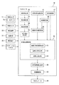
- the own vehicle 1 includes a vehicle control device 10 that automatically controls the traveling of the own vehicle 1.
- the vehicle control device 10 supports the driving of the own vehicle 1 by detecting the self-position which is the current position of the own vehicle 1 and controlling the traveling of the own vehicle 1 based on the detected self-position.
- the vehicle control device 10 supports driving by performing autonomous driving control that automatically drives the own vehicle 1 without the driver's involvement, based on the detected self-position and the surrounding driving environment.
- the vehicle control device 10 may support driving by controlling only acceleration / deceleration based on the estimated self-position and the surrounding traveling environment. For example, the vehicle control device 10 maintains a set speed when there is no preceding vehicle, and travels so as to follow the preceding vehicle when there is a preceding vehicle traveling at a speed lower than the set speed. Constant speed running control may be performed. The vehicle control device 10 may control the inter-vehicle distance from the preceding vehicle according to the vehicle speed of the own vehicle 1.
- the vehicle control device 10 includes an object sensor 11, a vehicle sensor 12, a positioning device 13, a map database 14, a communication device 15, a navigation system 17, a controller 18, and an actuator 19.
- the map database is referred to as "map DB".
- the object sensor 11 includes a plurality of different types of sensors that detect objects around the own vehicle 1.
- the object sensor 11 includes a camera 20 mounted on the own vehicle 1.
- the camera 20 captures an image of a predetermined angle of view range (imaging range) in front of the own vehicle 1 and outputs the captured image to the controller 18.
- imaging is also referred to as “shooting”, and is treated as having the same meaning in the present specification.
- the object sensor 11 may include a range finder such as a laser radar, a millimeter wave radar, or a LIDAR (Light Detection and Ranger, Laser Imaging Detection and Ranger).
- the vehicle sensor 12 is mounted on the own vehicle 1 and detects various information (vehicle signals) obtained from the own vehicle 1.
- the vehicle sensor 12 includes, for example, a vehicle speed sensor that detects the traveling speed (vehicle speed) of the own vehicle 1, a wheel speed sensor that detects the rotation speed of each tire included in the own vehicle 1, and an acceleration in the three axial directions of the own vehicle 1.
- G sensor 3-axis accelerometer
- steering angle sensor that detects steering angle (including steering angle)
- gyro sensor that detects angular speed generated in own vehicle 1
- yaw rate that detects yaw rate It includes a sensor, an accelerator sensor that detects the accelerator opening of the own vehicle, and a brake sensor that detects the amount of brake operation by the driver.
- the positioning device 13 includes a global positioning system (GNSS) receiver, receives radio waves from a plurality of navigation satellites, and measures the current position of the own vehicle 1.
- the GNSS receiver may be, for example, a Global Positioning System (GPS) receiver or the like.
- the positioning device 13 may be, for example, an inertial navigation system.
- the map database 14 may store high-precision map data (hereinafter, simply referred to as “high-precision map”) suitable as map information for automatic driving.
- the high-precision map is map data with higher accuracy than the map data for navigation (hereinafter, simply referred to as "navigation map”), and includes lane-based information that is more detailed than road-based information.
- the information for each lane included in the high-precision map data may be referred to as "lane information”.
- a high-precision map provides lane information such as lane node information indicating a reference point on a lane reference line (for example, a central line in a lane) and lane link information indicating a lane section mode between lane nodes.
- the lane node information includes the identification number of the lane node, the position coordinates, the number of connected lane links, and the identification number of the connected lane links.
- the lane link information includes the identification number of the lane link, the type of lane, the width of the lane, the type of the lane boundary line, the shape of the lane, the slope of the lane, the shape of the lane dividing line, and the shape of the lane reference line.
- the high-precision map also identifies the types and position coordinates of features such as stop lines, signs, buildings, utility poles, curbs, and pedestrian crossings that exist on or near the lane, and the lane nodes that correspond to the position coordinates of the features. Includes feature information such as numbers and lane link identification numbers.
- High-precision maps also include information on traffic lights that are on or near the lane.
- Traffic light information included in high-precision map data may be referred to as "traffic light information".
- the traffic light information includes information on the installation position of each traffic light and identification information of the stop line corresponding to the traffic light.
- the traffic light information identifies the lane in which traffic is regulated by this traffic light through the identification information of the stop line corresponding to the traffic light.
- the traffic light information may include, for example, information on a lane node at an intersection provided with a traffic light and information on a pedestrian crossing provided with a traffic light.
- the traffic light information identifies the lane in which traffic is regulated by this traffic light through this information.
- the lane where traffic is restricted by a traffic light is a lane where it is permitted or prohibited by the display of the traffic light to proceed ahead of the stop line provided corresponding to the traffic light, or the traffic light. It is a lane that is permitted or prohibited by the display of the traffic light to enter the intersection or pedestrian crossing provided with.
- the information on the installation position of the traffic light includes at least the two-dimensional coordinates of the map coordinate system (or the world coordinate system) of the position where the traffic light is installed.
- the information on the installation position of the traffic light may include the height information of the traffic light in addition to the two-dimensional coordinates of the position where the traffic light is installed. However, since the installation height of the traffic light is set within a predetermined range by law, the height of the traffic light does not necessarily have to be included in the high-precision map data.
- the communication device 15 performs wireless communication with an external communication device of the own vehicle 1.
- the communication method by the communication device 15 may be, for example, wireless communication by a public mobile phone network, vehicle-to-vehicle communication, road-to-vehicle communication, or satellite communication.
- the navigation system 17 recognizes the current position of the own vehicle 1 by the positioning device 13, and acquires the map information at the current position from the map database 14.
- the navigation system 17 sets a travel route to the destination input by the occupant, and guides the occupant according to the travel route. Further, the navigation system 17 outputs the information of the set traveling route to the controller 18.
- the controller 18 automatically drives the own vehicle 1 so as to travel along the traveling route set by the navigation system 17.
- the controller 18 is an electronic control unit (ECU: Electronic Control Unit) that controls the vehicle of the own vehicle 1.
- the controller 18 includes a processor 21 and peripheral components such as a storage device 22.
- the processor 21 may be, for example, a CPU (Central Processing Unit) or an MPU (Micro-Processing Unit).
- the storage device 22 may include a semiconductor storage device, a magnetic storage device, an optical storage device, and the like.
- the storage device 22 may include a memory such as a register, a cache memory, a ROM (Read Only Memory) and a RAM (Random Access Memory) used as a main storage device.
- the function of the controller 18 described below is realized, for example, by the processor 21 executing a computer program stored in the storage device 22.
- the controller 18 may be formed by dedicated hardware for executing each information processing described below.
- the controller 18 may include a functional logic circuit set in a general-purpose semiconductor integrated circuit.
- the controller 18 may have a programmable logic device (PLD: Programmable Logic Device) such as a field programmable gate array (FPGA: Field-Programmable Gate Array).
- PLD Programmable Logic Device
- FPGA Field-Programmable Gate Array
- the actuator 19 operates the steering wheel, accelerator opening degree, and brake device of the own vehicle 1 in response to the control signal from the controller 18 to generate the vehicle behavior of the own vehicle 1.
- the actuator 19 includes a steering actuator, an accelerator opening actuator, and a brake control actuator.
- the steering actuator controls the steering direction and steering amount of the steering of the own vehicle 1.
- the accelerator opening actuator controls the accelerator opening of the own vehicle 1.
- the brake control actuator controls the braking operation of the brake device of the own vehicle 1.
- the controller 18 recognizes a traffic light that regulates traffic in the lane in which the own vehicle 1 travels from the image captured by the camera 20.
- the controller 18 runs or stops the own vehicle 1 according to the indication of the recognized traffic light. As described above, if the angle of view range of the camera 20 is obstructed by the preceding vehicle traveling in front of the own vehicle 1, the traffic light may not be recognized from the captured image.
- the controller 18 determines the camera 20 based on the optical information of the camera 20 (for example, the angle of view information of the camera 20) and the installation information of the camera 20 (for example, the mounting position of the camera on the own vehicle 1 and the orientation of the optical system). Calculate the angle of view range (shooting range) of.
- the optical information and the installation information of the camera 20 are set in advance and stored in the storage device 22. If the installation information of the camera 20 (the mounting position of the camera with respect to the own vehicle 1 and the orientation of the optical system, etc.) does not change, that is, if the installation state of the camera with respect to the own vehicle 1 is fixed, the camera 20 with respect to the own vehicle Since the angle of view range is fixed, the installation information of the camera 20 is not always necessary. Based on the angle of view range of the camera 20 and the map information, the controller 18 calculates an imageable area in which the camera 20 can take a picture of a traffic light on the lane when the preceding vehicle does not exist.
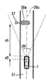
- the traffic light 30 is a traffic light that regulates traffic in a plurality of lanes 31 and 32.
- the traffic directions of the lanes 31 and 32 are the same, the lane 31 is the traveling lane of the own vehicle 1, and the lane 32 is an adjacent lane to the lane 31.
- the controller 18 photographs the traffic light 30 on the lane 31 by the camera 20 when there is no other vehicle on the road based on the traffic light information of the traffic light 30, the lane information of the lane 31, and the angle of view range of the camera 20.
- the imageable region 33 that can be imaged is calculated.
- the imageable region 33 is an region where it can be expected that the traffic light 30 can be photographed by the camera 20 on the lane 31 if the angle of view range of the camera 20 is not obstructed by the preceding vehicle 2.
- the area on the lane 31 outside the imageable area 33 is an area where the traffic light 30 cannot be photographed even if the angle of view range of the camera 20 is not obstructed.
- the controller 18 similarly calculates the imageable region 34 for the lane 32. That is, the controller 18 uses the traffic light 30 on the lane 32 by the camera 20 when there is no other vehicle on the road based on the traffic light information of the traffic light 30, the lane information of the lane 32, and the angle of view range of the camera 20.
- the imageable area 34 in which the image can be photographed is calculated.
- the controller 18 determines whether or not the own vehicle 1 is located in the imageable area 33 or 34. When the own vehicle 1 is located in the imageable region 33 or 34, it can be expected that the traffic light 30 can be photographed unless the angle of view range of the camera 20 is obstructed by the preceding vehicle. Therefore, in this case, the controller 18 controls the own vehicle 1 so that the traffic light 30 is not shielded from the angle of view range of the camera 20 by the preceding vehicle 2.
- the controller 18 calculates the inter-vehicle distance at which the traffic light 30 is not shielded by the preceding vehicle 2, and decelerates the own vehicle 1 according to the inter-vehicle distance. As a result, the distance between the preceding vehicle 2 and the own vehicle 1 is increased. In addition to or instead of this, the controller 18 increases the lateral position deviation between the own vehicle 1 and the preceding vehicle 2 in the direction in which the traffic light 30 deviates from the center of the lane 31. You may steer.
- the controller 18 maintains the distance between the preceding vehicle 2 and the own vehicle 1 at a distance at which the traffic light 30 is not shielded by the preceding vehicle 2.
- the speed of the own vehicle 1 is controlled so as to do so.
- the traveling control of the own vehicle 1 that prevents the traffic light 30 from being shielded from the angle of view range of the camera 20 by the preceding vehicle 2 is hereinafter referred to as "shielding avoidance control".
- the controller 18 is set to a target value set regardless of whether or not the traffic light 30 is shielded from the angle of view range of the camera 20 by the preceding vehicle 2. , Control the distance between the preceding vehicle 2 and the own vehicle 1.
- the controller 18 may set a target value of the inter-vehicle distance from the preceding vehicle according to the vehicle speed of the own vehicle 1.
- the controller 18 controls the lateral position of the own vehicle 1 so that the lateral position of the own vehicle 1 in the lane 31 which is the traveling lane of the own vehicle 1 becomes a predetermined initial value (for example, the center of the lane). You can.
- the controller 18 includes an object detection unit 40, an own vehicle position estimation unit 41, a map acquisition unit 42, a detection integration unit 43, an object tracking unit 44, a preceding vehicle detection unit 45, and a map position calculation unit 46.
- the signal recognition unit 47, the shielding avoidance control unit 48, the own vehicle route generation unit 49, and the vehicle control unit 50 are provided.
- the object detection unit 40 detects the position, posture, size, speed, and the like of objects around the own vehicle 1, such as a vehicle, a motorcycle, a pedestrian, and an obstacle, based on the detection signal of the object sensor 11.
- the object detection unit 40 outputs a detection result representing a two-dimensional position, posture, size, speed, etc. of an object in, for example, a zenith view (also referred to as a plan view) in which the own vehicle 1 is viewed from the air.
- the own vehicle position estimation unit 41 determines the absolute position of the own vehicle 1, that is, the position of the own vehicle 1 with respect to a predetermined reference point, based on the measurement result by the positioning device 13 and the odometry using the detection result from the vehicle sensor 12. , Measure posture and speed.
- the map acquisition unit 42 acquires map information of the road on which the own vehicle 1 travels from the map database 14.
- the map acquisition unit 42 may acquire map information from an external map data server by the communication device 15.
- the map information acquired by the map acquisition unit 42 includes traffic signal information of a traffic light existing in front of the course of the own vehicle 1, lane information of a lane whose traffic is regulated by this traffic light, and existing on or near the lane. Includes feature information.
- the detection integration unit 43 integrates a plurality of detection results obtained by the object detection unit 40 from each of the plurality of object detection sensors, and outputs one two-dimensional position, posture, size, speed, etc. for each object. To do. Specifically, from the behavior of the object obtained from each of the object detection sensors, the most rational behavior of the object with the least error is calculated in consideration of the error characteristics of each object detection sensor. Specifically, by using a known sensor fusion technique, the detection results acquired by a plurality of types of sensors are comprehensively evaluated to obtain more accurate detection results.
- the object tracking unit 44 tracks the object detected by the object detecting unit 40. Specifically, based on the detection result integrated by the detection integration unit 43, the identity of the object between different times is verified (associated) from the behavior of the objects output at different times, and the same is performed. Based on the association, the behavior such as the velocity of the object is predicted.
- the preceding vehicle detection unit 45 detects the preceding vehicle in front of the own vehicle 1 from the objects existing around the own vehicle 1 detected by the detection integration unit 43 and the object tracking unit 44, and shields and avoids the detection result. Output to the control unit 48.
- the position calculation unit 46 in the map estimates the position and posture of the own vehicle 1 on the map from the absolute position of the own vehicle 1 obtained by the own vehicle position estimation unit 41 and the map information acquired by the map acquisition unit 42. To do. Further, the position calculation unit 46 in the map identifies the road on which the own vehicle 1 is traveling and the lane in which the own vehicle 1 is traveling on the road. The position calculation unit 46 in the map outputs the position and posture of the own vehicle 1 on the map and the information of the lane in which the own vehicle 1 travels to the shielding avoidance control unit 48.
- the signal recognition unit 47 analyzes the image captured by the camera 20 and recognizes the traffic light and its lighting color. The signal recognition unit 47 outputs the recognition result of the traffic light to the shielding avoidance control unit 48.
- the shielding avoidance control unit 48 is based on the map information acquired by the map acquisition unit 42, the detection result of the preceding vehicle detection unit 45, the position of the own vehicle 1 specified by the position calculation unit 46 in the map, and the recognition result of the signal recognition unit 47. Therefore, the shielding avoidance control for preventing the traffic light in front of the own vehicle 1 from being shielded from the angle of view range of the camera 20 by the preceding vehicle is executed.
- the shading avoidance control unit 48 includes an imageable area calculation unit 51, a shooting possibility determination unit 52, and a control amount setting unit 53.
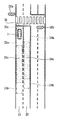
- the imageable area calculation unit 51 can photograph the traffic light in front of the own vehicle 1 with the camera 20 from the lane regulated by the traffic light based on the optical information and installation information of the camera 20 and the map information. Is calculated. See FIG. It is assumed that the traffic lights 30a and 30b are present in front of the own vehicle 1.
- the traffic lights 30a and 30b are traffic lights that regulate traffic in a plurality of lanes 31 and 32.
- the traffic directions of lanes 31 and 32 are the same and adjacent lanes.
- the imageable area calculation unit 51 calculates an imageable area for each of the plurality of lanes 31 and 32. First, the calculation of the imageable area on the lane 31 will be described. First, the image-capable area calculation unit 51 calculates an image-capable area 33a of the plurality of traffic lights 30a and 30b in which the traffic light 30a can be photographed. The imageable area calculation unit 51 calculates the imageable area 33a based on the installation position and height information of the traffic light 30a, the road structure and slope of the lane 31, and the optical information and installation information of the camera 20.
- the imageable area calculation unit 51 may calculate the imageable area 33a by searching for a point on the lane 31 where the traffic light 30a can be photographed. At this time, the imageable area calculation unit 51 determines that the camera 20 can shoot the signal 30a when the signal 30a is located in both the vertical and horizontal angles of view of the camera 20, and determines that the camera 20 can shoot the signal 30a. When the signal device 30a deviates from any of the angle-of-view ranges in the direction, it may be determined that the camera 20 cannot shoot the signal device 30a. See FIG. 5A. The imageable region calculation unit 51 determines that the traffic light 30a is located in the vertical angle of view range of the camera 20, for example, when the following equations (1) and (2) are satisfied.
- xb is the horizontal distance from the own vehicle 1 to the traffic light 30a
- x0 is the front-rear distance from the front end of the own vehicle 1 to the mounting position of the camera 20
- yc is the height of the mounting position of the camera 20
- ys1 is the height of the upper end of the traffic light 30a
- ys2 is the height of the lower end of the traffic light 30a.
- ⁇ 1 is the elevation angle of the upper limit 35 of the angle of view range of the camera 20, and ⁇ 2 is the elevation angle of the lower limit 36 of the angle of view range of the camera 20.
- a value assumed as the height of a general traffic light based on the installation standard set by an administrative agency or the like is used as the height of the traffic light 30a. You may. For example, ys1 may be assumed to be 5.7 m and ys2 may be assumed to be 4.7 m.
- the distance (x0) in the front-rear direction from the front end of the own vehicle 1 to the mounting position of the camera 20 is the height of the mounting position of the camera 20 (x0).
- the elevation angle ( ⁇ 1) of the upper limit 35 of the angle of view range of the camera 20, and the elevation angle ( ⁇ 2) of the lower limit 36 of the angle of view range of the camera 20 do not change. That is, when the camera 20 is fixed to the own vehicle 1, the vertical angle of view range of the camera 20 with respect to the own vehicle 1 does not change. Therefore, the vertical angle of view range of the camera 20 with respect to the own vehicle 1 is stored in advance.
- the camera 20 by detecting only the horizontal distance (xb) from the own vehicle 1 to the signal 30a, it can be determined that the signal 30a is located in the vertical angle of view range of the camera 20.
- the camera 20 is not fixed to the own vehicle 1 but is movable, or when the change in the angle of view range due to the pitching operation of the own vehicle 1 is taken into consideration, the camera is naturally taken from the front end of the actual own vehicle 1.
- the elevation angle ( ⁇ 2) may be detected, and it may be determined whether or not the signal 30a is located in the vertical angle of view range of the camera 20 by using the above equations (1) and (2).
- the imageable region calculation unit 51 is based on the lateral deviation of the signal 30a with respect to the optical center 20c of the camera 20, the horizontal distance (xb + x0) from the camera 20 to the signal 30a, and the horizontal angle of view ⁇ h of the camera 20. It is determined whether or not the signal 30a is located in the horizontal angle of view range of the camera 20. At this time, it may be assumed that the own vehicle 1 is located in the center of the lane 31. Further, when the installation position information of the traffic light 30a included in the map information is the two-dimensional coordinates of the support column 37 of the signal device 30a, the coordinates of the support column 37 may be used as the coordinates of the signal device 30a.
- the point closest to the traffic light in the imageable area is referred to as the "near end” of the imageable area
- the point farthest to the traffic light in the imageable area is referred to as the "far end” of the imageable area.
- the near end of the imageable region 33a is indicated by reference numeral 33c
- the far end of the imageable region 33a is indicated by reference numeral 33d.
- the upper limit of the distance between the far end 33d of the imageable region 33a and the traffic light 30a may be determined in consideration of the performance of the optical system of the camera 20.
- the far end 33d may be set according to the minimum number of pixels required to recognize the traffic light 30a on the captured image.
- the far end 33d may be set so that the distance from the traffic light 30a to the far end 33d is equal to or less than the threshold value.
- the image-capable area calculation unit 51 calculates the image-capable area 33b for the traffic light 30b so that the traffic light 30b can be photographed on the lane 31. In this way, the imageable area calculation unit 51 calculates the imageable areas 33a and 33b at which the traffic lights 30a and 30b can be photographed on the lane 31 for each of the traffic lights 30a and 30b that regulate the lane 31.
- the imageable region calculation unit 51 sets the sum region of the imageable regions 33a and 33b (that is, the region included in at least one of the imageable regions 33a or 33b) at least in the traffic light 30a or 30b that regulates the lane 31. One is calculated as an imageable area that can be photographed on the lane 31. Further, the image-capable area calculation unit 51 calculates the overlapping area 33e of the image-capable area 33a and 33b.
- the imageable area calculation unit 51 calculates the imageable area on the adjacent lane 32 of the lane 31. Similar to the case of the lane 31, the image-capable area calculation unit 51 calculates an image-capable area 34a in which the traffic light 30a can be photographed on the lane 32 and an image-capable area 34b in which the traffic light 30b can be photographed on the lane 32.
- the imageable region calculation unit 51 calculates the sum region of the imageable regions 34a and 34b as an imageable region in which at least one of the traffic lights 30a or 30b that regulates the lane 32 can be photographed on the lane 32. Further, the image-capable area calculation unit 51 calculates the overlapping area 34c of the image-capable area 34a and 34b.
- the shooting possibility determination unit 52 determines whether or not the own vehicle 1 is located in the imageable area calculated by the imageable area calculation unit 51 (for example, whether or not the own vehicle 1 is traveling in the imageable area). judge. In the examples of FIGS. 4 and 6, the photographing possibility determination unit 52 determines whether or not the own vehicle 1 is located in either the sum region of the imageable regions 33a and 33b or the sum region of the imageable regions 34a and 34b. judge. That is, the shooting possibility determination unit 52 determines whether or not the own vehicle 1 is located in any of the imageable regions 33a, 33b, 34a, or 34b.
- the control amount setting unit 53 shields the traffic light according to the recognition state of the traffic light by the signal recognition unit 47 and the detection result of the preceding vehicle by the preceding vehicle detection unit 45.
- the target control amount of the traveling control of the own vehicle 1 for avoidance control is set.
- the control amount setting unit 53 sets, for example, the target inter-vehicle distance between the own vehicle 1 and the preceding vehicle as the target control amount, or the target lateral position of the own vehicle 1 in the traveling lane. See FIG. 7. It is assumed that the shooting possibility determination unit 52 determines that the own vehicle 1 is located in the imageable region, and the preceding vehicle detection unit 45 detects the preceding vehicle 2.
- the control amount setting unit 53 determines whether or not the signal recognition unit 47 recognizes the traffic light 30a or 30b. When the signal recognition unit 47 determines that the traffic light 30a or 30b is recognized, the control amount setting unit 53 determines that the current inter-vehicle distance is the image of the camera 20 by the preceding vehicle 2 at least one of the traffic lights 30a or 30b. Judge that the inter-vehicle distance is not shielded from the angle range, and set the current inter-vehicle distance as the target inter-vehicle distance.
- the control amount setting unit 53 does not shield at least one of the traffic light 30a or 30b from the angle of view range of the camera 20 by the preceding vehicle 2. As such, the target control amount is set. For example, when it is determined that the own vehicle 1 is located within the imageable region 33a, the control amount setting unit 53 calculates the inter-vehicle distance at which the traffic light 30a is not shielded by the preceding vehicle 2 and sets it as the target inter-vehicle distance.
- the preceding vehicle 2 and the signal recognition unit 47 are regarded as the preceding vehicle 2. It is determined that the inter-vehicle distance from the own vehicle 1 is short and the traffic light 30a is shielded by the preceding vehicle 2, and the inter-vehicle distance between the preceding vehicle 2 and the own vehicle 1 is set to the inter-vehicle distance where the traffic light 30a is not shielded by the preceding vehicle 2. Increase.
- control amount setting unit 53 calculates the inter-vehicle distance x1 in which the traffic light 30a is not shielded by the preceding vehicle 2 by the following equation (3).
- x1 (xb + x0) x (yt-yc) / (ys-yc) -x0 ...
- yy indicates the height of the preceding vehicle 2
- ys indicates the height of the traffic light 30a.
- control amount setting unit 53 calculates the inter-vehicle distance at which the traffic light 30b is not shielded by the preceding vehicle 2 and sets it as the target inter-vehicle distance.
- the control amount setting unit 53 determines the inter-vehicle distance in which the traffic light 30a is not shielded by the preceding vehicle 2 and the traffic light 30b is shielded by the preceding vehicle 2.
- One of the inter-vehicle distances that are not set may be calculated and set as the target inter-vehicle distance.
- the control amount setting unit 53 calculates both the inter-vehicle distance in which the traffic light 30a is not shielded by the preceding vehicle 2 and the inter-vehicle distance in which the traffic light 30b is not shielded by the preceding vehicle 2, and sets a shorter inter-vehicle distance among these inter-vehicle distances as the target inter-vehicle distance. It may be set to, or a longer inter-vehicle distance may be set as the target inter-vehicle distance.
- the control amount setting unit 53 may set a target lateral position of the own vehicle 1 in the traveling lane 31. That is, the control amount setting unit 53 may set the lateral position in the traveling lane 31 that increases the deviation between the lateral positions of the own vehicle 1 and the preceding vehicle 2 as the target lateral position. For example, when it is determined that the own vehicle 1 is located within the imageable region 33a, the control amount setting unit 53 determines whether or not the traffic light 30a is deviated from the center of the lane 31.
- the control amount setting unit 53 determines that the traffic light 30a is deviated from the center of the lane 31.
- the target lateral position is set so that the deviation ⁇ of the lateral position between the own vehicle 1 and the preceding vehicle 2 increases in the direction of deviation. Since the traffic light 30a is deviated from the center of the lane 31 to the left, the control amount setting unit 53 sets the target lateral position so that the deviation ⁇ increases to the left.
- the control amount setting unit 53 determines whether or not the traffic light 30b is deviated from the center of the lane 31.
- the control amount setting unit 53 determines the deviation ⁇ of the lateral position between the own vehicle 1 and the preceding vehicle 2 in the direction in which the traffic light 30b deviates from the center of the lane 31. Set the target horizontal position to increase.
- the control amount setting unit 53 sets the target lateral position so that the deviation ⁇ increases to the right.
- the control amount setting unit 53 may set the target lateral position so that the deviation ⁇ increases in the left direction.
- the target lateral position may be set so that the deviation ⁇ increases in the direction.
- the shooting possibility determination unit 52 determines that the own vehicle 1 is located in the imageable region, and the preceding vehicle detection unit 45 does not detect the preceding vehicle 2. Even in such a case, the signal recognition unit 47 may not be able to recognize the traffic light 30a or 30b depending on the shooting conditions such as the direction of the sun's rays and the device state of the camera 20. Therefore, the control amount setting unit 53 determines whether or not the signal recognition unit 47 recognizes the traffic light 30a or 30b.
- the control amount setting unit 53 sets the position far from the traffic light 30a of the stop line 38 or the near end 33c of the imageable region 33a as the target stop position.
- the control amount setting unit 53 suppresses the above-mentioned occlusion avoidance control. For example, even if the control amount setting unit 53 determines that the signal recognition unit 47 does not recognize the traffic light 30a or the traffic light 30b, the traffic light 30a or 30b is camerad by the preceding vehicle 2 in the autonomous driving control or the constant speed driving control. The target inter-vehicle distance and the target lateral position are not changed regardless of whether or not the vehicle is shielded from the 20 angle of view range.
- the target control amount for avoidance control can be set.
- the own vehicle route generation unit 49 follows the traveling lane of the own vehicle 1 based on the detection result of the object around the own vehicle 1 by the detection integration unit 43 and the object tracking unit 44 and the vehicle signal from the vehicle sensor 12.
- the target traveling track and speed profile of the own vehicle 1 are generated so that the vehicle travels according to the traffic rules without colliding with other vehicles.
- the own vehicle route generation unit 49 generates a speed profile so that the inter-vehicle distance between the own vehicle 1 and the preceding vehicle becomes the target inter-vehicle distance set by the shielding avoidance control unit 48.
- the own vehicle route generation unit 49 generates a target traveling track that changes the lateral position of the own vehicle 1 in the lane to the target lateral position set by the shielding avoidance control unit 48.
- the lateral position of the own vehicle 1 and the preceding vehicle is located in the direction in which the traffic light deviates from the center of the traveling lane of the own vehicle 1.
- a target driving track that increases the deviation is generated.
- the own vehicle route generation unit 49 generates a target traveling track and a speed profile for stopping the own vehicle at the target stop position set by the shielding avoidance control unit 48.
- the vehicle control unit 50 drives the actuator 19 so that the vehicle 1 travels on the target travel track at a speed according to the speed profile generated by the vehicle route generation unit 49.
- the vehicle control unit 50 controls the brake control actuator to control the own vehicle 1. Decelerate.
- the vehicle control unit 50 controls the accelerator opening actuator and the brake control actuator to maintain the inter-vehicle distance from the preceding vehicle. To do.
- the vehicle control unit 50 controls the steering actuator to steer the own vehicle 1 and changes the lateral position of the own vehicle 1 to the set target lateral position. Let me.
- the vehicle control unit 50 stops the own vehicle at the set target stop position.
- the control amount setting unit 53 determines. It is determined whether or not the signal recognition unit 47 recognizes the traffic light. Even if the inter-vehicle distance between the own vehicle 1 and the preceding vehicle becomes the target inter-vehicle distance, if the signal recognition unit 47 determines that the traffic light is not recognized, a factor other than the preceding vehicle (for example, shooting conditions or the camera 20) It is considered that the traffic light cannot be recognized because of the device state).
- the control amount setting unit 53 targets the stop line 38 or the near end 33c of the imageable region 33a at a position farther from the traffic light 30a. Set to position.
- the signal recognition unit 47 cannot recognize the traffic light 30a or 30b even if the lateral position of the own vehicle 1 becomes the maximum allowable lateral position as a result of the increase in the lateral position deviation ⁇ between the own vehicle 1 and the preceding vehicle 2. is there.
- step S1 the controller 18 sets the target inter-vehicle distance and the target lateral position in autonomous travel control and constant speed travel control.
- the controller 18 may set the target inter-vehicle distance according to the vehicle speed of the own vehicle 1. Further, for example, the controller 18 may set the center of the traveling lane of the own vehicle 1 to the target lateral position.
- step S2 the map acquisition unit 42 acquires map information of the road on which the own vehicle 1 travels.
- step S3 the signal recognition unit 47 acquires an image captured by the camera 20. The signal recognition unit 47 analyzes the image captured by the camera 20 and recognizes the traffic light and its lighting color.
- step S4 the own vehicle position estimation unit 41 estimates the current position of the own vehicle 1.
- step S5 the preceding vehicle detection unit 45 detects the preceding vehicle in front of the own vehicle 1.
- step S6 the imageable area calculation unit 51 calculates an imageable area in which the camera 20 can image a traffic light on the lane.
- step S7 the shooting possibility determination unit 52 determines whether or not the own vehicle 1 is located in the imageable region. When it is determined that the own vehicle 1 is not located in the imageable region (step S7: N), the process proceeds to step S8.
- step S8 the own vehicle route generation unit 49 and the vehicle control unit 50 control the traveling of the own vehicle according to the target inter-vehicle distance and the target lateral position set in step S1. Therefore, the shielding avoidance control by the shielding avoidance control unit 48 is suppressed. After that, the process ends.
- step S7 when it is determined in step S7 that the own vehicle 1 is located in the imageable region (step S7: Y), the process proceeds to step S9.
- step S9 the control amount setting unit 53 determines whether or not the signal recognition unit 47 recognizes the traffic light.
- step S9: Y the process proceeds to step S10.
- step S9: N the process proceeds to step S12.
- step S10 the control amount setting unit 53 determines whether or not the preceding vehicle detection unit 45 has detected the preceding vehicle 2.
- step S11 the control amount setting unit 53 determines that the current inter-vehicle distance is the inter-vehicle distance at which the traffic light is not shielded from the angle of view range of the camera 20 by the preceding vehicle, and the target inter-vehicle distance is maintained so as to maintain the current inter-vehicle distance. Set as. After that, the process proceeds to step S8. In step S8, the own vehicle route generation unit 49 and the vehicle control unit 50 control the vehicle speed of the own vehicle 1 so as to maintain the current inter-vehicle distance set as the target inter-vehicle distance. After that, the process ends.
- step S10 when it is determined in step S10 that the preceding vehicle detection unit 45 has not detected the preceding vehicle 2 (step S10: N), the process proceeds to step S8.
- step S8 the own vehicle route generation unit 49 and the vehicle control unit 50 control the traveling of the own vehicle according to the target inter-vehicle distance and the target lateral position set in step S1. After that, the process ends.
- step S12 the control amount setting unit 53 determines whether or not the preceding vehicle detection unit 45 has detected the preceding vehicle 2. When it is determined that the preceding vehicle detection unit 45 has detected the preceding vehicle 2 (step S12: Y), the process proceeds to step S13.
- step S13 the control amount setting unit 53 calculates the inter-vehicle distance at which the traffic light 3 is not shielded by the preceding vehicle, and sets the target inter-vehicle distance. This increases the target inter-vehicle distance.
- step S8 the own vehicle route generation unit 49 and the vehicle control unit 50 decelerate the own vehicle 1 so that the inter-vehicle distance between the own vehicle 1 and the preceding vehicle becomes the target inter-vehicle distance set by the control amount setting unit 53.
- the own vehicle route generation unit 49 and the vehicle control unit 50 steer the own vehicle 1 so that the lateral position of the own vehicle 1 changes to the target lateral position. After that, the process ends.
- step S12 determines whether the preceding vehicle detection unit 45 has not detected the preceding vehicle 2 (step S12: N). If it is determined in step S12 that the preceding vehicle detection unit 45 has not detected the preceding vehicle 2 (step S12: N), the process proceeds to step S14.
- step S14 the control amount setting unit 53 sets the position far from the traffic light at the near end of the imageable region or the stop line as the target stop position. After that, the process proceeds to step S8.
- step S8 the own vehicle route generation unit 49 and the vehicle control unit 50 stop the own vehicle 1 at the target stop position. After that, the process ends.
- the signal recognition unit 47 recognizes a traffic light based on an image captured by a camera 20 that captures a predetermined angle of view range in front of the own vehicle 1.
- the map acquisition unit 42 acquires map information including information on the installation position of the traffic light and information on the lane regulated by the traffic light.
- the imageable area calculation unit 51 calculates an imageable area in which the camera 20 can image a traffic light on the lane based on the angle of view range of the camera 20 mounted on the own vehicle 1 and the map information.
- the shooting possibility determination unit 52 determines whether or not the own vehicle 1 is located within the imageable region.
- the control amount setting unit 53, the own vehicle route generation unit 49, and the vehicle control unit 50 have the angle of view of the camera 20 as a traffic light depending on the preceding vehicle of the own vehicle 1.
- the own vehicle 1 is controlled so as not to be shielded from the range. As a result, it is possible to prevent unnecessary shielding avoidance control from being executed in an area where the camera 20 cannot capture a traffic light in the first place even if no other vehicle is present in the lane. As a result, it is possible to suppress unnecessary discomfort to the occupants of the own vehicle 1 by the shielding avoidance control.
- the control amount setting unit 53 determines whether or not the traffic light is recognized from the image captured by the camera 20, and when the traffic light is recognized from the captured image, the own vehicle route generation unit 49 and the vehicle control unit 50. Controls the own vehicle so that the inter-vehicle distance between the preceding vehicle and the own vehicle is maintained at an inter-vehicle distance in which the traffic light is not shielded by the preceding vehicle. This makes it possible to control the own vehicle 1 so that the traffic light is not blocked by the preceding vehicle.
- the control amount setting unit 53 determines whether or not the traffic light is recognized from the image captured by the camera 20, and determines whether or not the preceding vehicle exists.
- the control amount setting unit 53 and the own vehicle route generation unit 49 The vehicle control unit 50 controls the own vehicle 1 so as to increase the inter-vehicle distance between the preceding vehicle and the own vehicle 1. This makes it possible to control the own vehicle 1 so that the traffic light is not blocked by the preceding vehicle.
- the control amount setting unit 53 calculates the inter-vehicle distance at which the traffic light is not shielded by the preceding vehicle.
- the own vehicle route generation unit 49 and the vehicle control unit 50 increase the inter-vehicle distance between the preceding vehicle and the own vehicle by decelerating the own vehicle 1 according to the inter-vehicle distance. This makes it possible to control the speed of the own vehicle 1 so that the traffic light is not blocked by the preceding vehicle.
- the control amount setting unit 53, the own vehicle route generation unit 49, and the vehicle control unit 50 increase the deviation of the lateral position between the own vehicle 1 and the preceding vehicle in the direction in which the traffic light deviates from the center of the lane. Steer the own vehicle 1. This makes it possible to steer the own vehicle 1 so that the traffic light is not blocked by the preceding vehicle.
- the control amount setting unit 53, the own vehicle route generation unit 49, and the vehicle control unit 50 stop corresponding to the traffic light.
- the own vehicle 1 is stopped at a position closest to the traffic light in the line or the imageable area, which is farther from the traffic light.
- the own vehicle 1 can be stopped at a point where the traffic light is located within the angle of view range of the camera 20 without crossing the stop line. ..
- the own vehicle 1 can be stopped at a position where the traffic light can be photographed when the situation improves.
- the control amount setting unit 53 determines whether or not the traffic light is recognized from the image captured by the camera 20, and determines whether or not the preceding vehicle exists. When the traffic light is not recognized from the captured image and the preceding vehicle does not exist, the control amount setting unit 53, the own vehicle route generation unit 49, and the vehicle control unit 50 are within the stop line corresponding to the traffic light or the imageable region. The own vehicle 1 is stopped at a position closest to the traffic light, which is farther from the traffic light. As a result, when the traffic light cannot be recognized due to factors other than the preceding vehicle such as shooting conditions and device state, the own vehicle 1 can be stopped at a point where the traffic light is located within the angle of view range of the camera 20 without crossing the stop line. .. As a result, the own vehicle 1 can be stopped at a position where the traffic light can be photographed when the situation improves.
- the map acquisition unit 42 acquires information on the installation positions of a plurality of traffic lights that regulate lanes from the map information.
- the imageable area calculation unit 51 calculates the imageable area for each of the plurality of traffic lights.
- the traffic light is the angle of view of the camera 20 by the preceding vehicle.
- the own vehicle 1 is controlled so as not to be shielded from the range. Since it is sufficient to control the own vehicle 1 so that one of the plurality of traffic lights is not shielded, the options for the traveling control of the own vehicle 1 increase.
- the imageable area calculation unit 51 calculates an imageable area for each of a plurality of lanes controlled by a traffic light. Since it is sufficient to control the own vehicle 1 so that the traffic light is not shielded in any one of the plurality of lanes, the options for the traveling control of the own vehicle 1 increase.
Landscapes
- Engineering & Computer Science (AREA)
- Automation & Control Theory (AREA)
- Transportation (AREA)
- Mechanical Engineering (AREA)
- Physics & Mathematics (AREA)
- General Physics & Mathematics (AREA)
- Multimedia (AREA)
- Theoretical Computer Science (AREA)
- Traffic Control Systems (AREA)
- Control Of Driving Devices And Active Controlling Of Vehicle (AREA)
Priority Applications (7)
| Application Number | Priority Date | Filing Date | Title |
|---|---|---|---|
| BR112022009416A BR112022009416A2 (pt) | 2019-11-15 | 2019-11-15 | Método para controlar veículo e dispositivo de controle de veículo |
| CN201980102251.1A CN114728657B (zh) | 2019-11-15 | 2019-11-15 | 车辆控制方法及车辆控制装置 |
| EP19952758.1A EP4059795B1 (en) | 2019-11-15 | 2019-11-15 | Method for controlling vehicle and vehicle control device |
| US17/776,489 US11987245B2 (en) | 2019-11-15 | 2019-11-15 | Method for controlling vehicle and vehicle control device |
| MX2022005699A MX2022005699A (es) | 2019-11-15 | 2019-11-15 | Metodo para controlar vehiculo y dispositivo de control de vehiculo. |
| PCT/IB2019/001272 WO2021094802A1 (ja) | 2019-11-15 | 2019-11-15 | 車両制御方法及び車両制御装置 |
| JP2021555895A JP7334795B2 (ja) | 2019-11-15 | 2019-11-15 | 車両制御方法及び車両制御装置 |
Applications Claiming Priority (1)
| Application Number | Priority Date | Filing Date | Title |
|---|---|---|---|
| PCT/IB2019/001272 WO2021094802A1 (ja) | 2019-11-15 | 2019-11-15 | 車両制御方法及び車両制御装置 |
Publications (1)
| Publication Number | Publication Date |
|---|---|
| WO2021094802A1 true WO2021094802A1 (ja) | 2021-05-20 |
Family
ID=75912060
Family Applications (1)
| Application Number | Title | Priority Date | Filing Date |
|---|---|---|---|
| PCT/IB2019/001272 Ceased WO2021094802A1 (ja) | 2019-11-15 | 2019-11-15 | 車両制御方法及び車両制御装置 |
Country Status (7)
| Country | Link |
|---|---|
| US (1) | US11987245B2 (https=) |
| EP (1) | EP4059795B1 (https=) |
| JP (1) | JP7334795B2 (https=) |
| CN (1) | CN114728657B (https=) |
| BR (1) | BR112022009416A2 (https=) |
| MX (1) | MX2022005699A (https=) |
| WO (1) | WO2021094802A1 (https=) |
Cited By (3)
| Publication number | Priority date | Publication date | Assignee | Title |
|---|---|---|---|---|
| WO2023072478A1 (de) * | 2021-10-26 | 2023-05-04 | Mercedes-Benz Group AG | Verfahren zur automatischen regelung einer längsbewegung eines fahrzeuges |
| JP2024108541A (ja) * | 2023-01-31 | 2024-08-13 | ダイハツ工業株式会社 | 運転支援装置 |
| JP2024108542A (ja) * | 2023-01-31 | 2024-08-13 | ダイハツ工業株式会社 | 運転支援装置 |
Families Citing this family (11)
| Publication number | Priority date | Publication date | Assignee | Title |
|---|---|---|---|---|
| JP7431108B2 (ja) * | 2020-06-02 | 2024-02-14 | 株式会社Soken | 画像認識装置 |
| US12005926B2 (en) * | 2020-12-31 | 2024-06-11 | Waymo Llc | Traffic light viewsheds |
| DE102021003918A1 (de) * | 2021-07-30 | 2023-02-02 | Mercedes-Benz Group AG | Verfahren zur Bestimmung einer Aktionsstrategie eines im automatisierten Fahrbetrieb fahrenden Fahrzeuges |
| DE102021209977A1 (de) * | 2021-09-09 | 2023-03-09 | Robert Bosch Gesellschaft mit beschränkter Haftung | Verfahren und Steuergerät |
| US12248325B2 (en) * | 2021-10-18 | 2025-03-11 | Y.E. Hub Armenia LLC | Mobile robot and a method for controlling the mobile robot |
| JP7442948B2 (ja) * | 2021-10-18 | 2024-03-05 | 矢崎総業株式会社 | 車外表示装置 |
| KR20230168859A (ko) * | 2022-06-08 | 2023-12-15 | 현대모비스 주식회사 | 자동차 조명 장치 및 그 작동 방법 |
| US12526517B2 (en) * | 2022-07-28 | 2026-01-13 | Ricoh Company, Ltd. | Method for capturing image, method for processing image, image capturing system, and information processing system |
| KR20240068861A (ko) | 2022-11-09 | 2024-05-20 | 삼성전자주식회사 | 자율 주행 계획 장치 및 방법 |
| US12260749B2 (en) * | 2023-01-31 | 2025-03-25 | GM Global Technology Operations LLC | Methods and systems for sensor fusion for traffic intersection assist |
| DE102023130485B3 (de) * | 2023-11-03 | 2025-01-23 | Bayerische Motoren Werke Aktiengesellschaft | Fahrassistenzsystem und Fahrassistenzverfahren für ein Fahrzeug |
Citations (8)
| Publication number | Priority date | Publication date | Assignee | Title |
|---|---|---|---|---|
| JP2007320458A (ja) * | 2006-06-01 | 2007-12-13 | Toyota Motor Corp | 車間距離制御装置 |
| JP2009001245A (ja) * | 2007-06-25 | 2009-01-08 | Hitachi Ltd | 車両走行支援制御装置 |
| JP2015125708A (ja) * | 2013-12-27 | 2015-07-06 | 富士重工業株式会社 | 信号機認識装置 |
| JP2016501408A (ja) * | 2012-12-03 | 2016-01-18 | コンティ テミック マイクロエレクトロニック ゲゼルシャフト ミットベシュレンクテル ハフツングConti Temic microelectronic GmbH | 信号を認識する車両の信号フェーズ・アシスタントをサポートするための方法 |
| JP2016049933A (ja) * | 2014-09-02 | 2016-04-11 | アイシン・エィ・ダブリュ株式会社 | 走行支援システム、走行支援方法及びコンピュータプログラム |
| JP2017154512A (ja) * | 2016-02-29 | 2017-09-07 | 日立オートモティブシステムズ株式会社 | 車両制御装置 |
| JP2019046136A (ja) * | 2017-09-01 | 2019-03-22 | 株式会社デンソー | 衝突回避支援装置 |
| JP2019079398A (ja) * | 2017-10-26 | 2019-05-23 | トヨタ自動車株式会社 | 走行制御装置 |
Family Cites Families (6)
| Publication number | Priority date | Publication date | Assignee | Title |
|---|---|---|---|---|
| JP5970858B2 (ja) * | 2012-02-29 | 2016-08-17 | 日産自動車株式会社 | 車両制御装置及び車両制御方法 |
| US8793046B2 (en) * | 2012-06-01 | 2014-07-29 | Google Inc. | Inferring state of traffic signal and other aspects of a vehicle's environment based on surrogate data |
| EP3306589B1 (en) | 2015-06-05 | 2019-01-09 | Nissan Motor Co., Ltd. | Traffic signal detection device and traffic signal detection method |
| CN110325421B (zh) * | 2017-03-03 | 2022-07-15 | 日立安斯泰莫株式会社 | 移动体行驶辅助装置及方法 |
| JP2019079126A (ja) | 2017-10-20 | 2019-05-23 | トヨタ自動車株式会社 | 車両 |
| JP7067067B2 (ja) * | 2018-01-11 | 2022-05-16 | トヨタ自動車株式会社 | 信号機認識装置、及び自動運転システム |
-
2019
- 2019-11-15 JP JP2021555895A patent/JP7334795B2/ja active Active
- 2019-11-15 WO PCT/IB2019/001272 patent/WO2021094802A1/ja not_active Ceased
- 2019-11-15 CN CN201980102251.1A patent/CN114728657B/zh active Active
- 2019-11-15 EP EP19952758.1A patent/EP4059795B1/en active Active
- 2019-11-15 BR BR112022009416A patent/BR112022009416A2/pt not_active Application Discontinuation
- 2019-11-15 MX MX2022005699A patent/MX2022005699A/es unknown
- 2019-11-15 US US17/776,489 patent/US11987245B2/en active Active
Patent Citations (8)
| Publication number | Priority date | Publication date | Assignee | Title |
|---|---|---|---|---|
| JP2007320458A (ja) * | 2006-06-01 | 2007-12-13 | Toyota Motor Corp | 車間距離制御装置 |
| JP2009001245A (ja) * | 2007-06-25 | 2009-01-08 | Hitachi Ltd | 車両走行支援制御装置 |
| JP2016501408A (ja) * | 2012-12-03 | 2016-01-18 | コンティ テミック マイクロエレクトロニック ゲゼルシャフト ミットベシュレンクテル ハフツングConti Temic microelectronic GmbH | 信号を認識する車両の信号フェーズ・アシスタントをサポートするための方法 |
| JP2015125708A (ja) * | 2013-12-27 | 2015-07-06 | 富士重工業株式会社 | 信号機認識装置 |
| JP2016049933A (ja) * | 2014-09-02 | 2016-04-11 | アイシン・エィ・ダブリュ株式会社 | 走行支援システム、走行支援方法及びコンピュータプログラム |
| JP2017154512A (ja) * | 2016-02-29 | 2017-09-07 | 日立オートモティブシステムズ株式会社 | 車両制御装置 |
| JP2019046136A (ja) * | 2017-09-01 | 2019-03-22 | 株式会社デンソー | 衝突回避支援装置 |
| JP2019079398A (ja) * | 2017-10-26 | 2019-05-23 | トヨタ自動車株式会社 | 走行制御装置 |
Cited By (8)
| Publication number | Priority date | Publication date | Assignee | Title |
|---|---|---|---|---|
| WO2023072478A1 (de) * | 2021-10-26 | 2023-05-04 | Mercedes-Benz Group AG | Verfahren zur automatischen regelung einer längsbewegung eines fahrzeuges |
| JP2024540023A (ja) * | 2021-10-26 | 2024-10-31 | メルセデス・ベンツ グループ アクチェンゲゼルシャフト | 車両の前後方向運動を自動的にコントロールする方法 |
| JP7734278B2 (ja) | 2021-10-26 | 2025-09-04 | メルセデス・ベンツ グループ アクチェンゲゼルシャフト | 車両の前後方向運動を自動的にコントロールする方法 |
| US12612045B2 (en) | 2021-10-26 | 2026-04-28 | Mercedes-Benz Group AG | Method for automatically regulating a longitudinal movement of a vehicle |
| JP2024108541A (ja) * | 2023-01-31 | 2024-08-13 | ダイハツ工業株式会社 | 運転支援装置 |
| JP2024108542A (ja) * | 2023-01-31 | 2024-08-13 | ダイハツ工業株式会社 | 運転支援装置 |
| JP7611950B2 (ja) | 2023-01-31 | 2025-01-10 | ダイハツ工業株式会社 | 運転支援装置 |
| JP7614239B2 (ja) | 2023-01-31 | 2025-01-15 | ダイハツ工業株式会社 | 運転支援装置 |
Also Published As
| Publication number | Publication date |
|---|---|
| CN114728657B (zh) | 2025-07-01 |
| JP7334795B2 (ja) | 2023-08-29 |
| US11987245B2 (en) | 2024-05-21 |
| MX2022005699A (es) | 2022-06-08 |
| CN114728657A (zh) | 2022-07-08 |
| JPWO2021094802A1 (https=) | 2021-05-20 |
| EP4059795A1 (en) | 2022-09-21 |
| US20220402492A1 (en) | 2022-12-22 |
| BR112022009416A2 (pt) | 2022-08-09 |
| EP4059795A4 (en) | 2022-12-21 |
| EP4059795B1 (en) | 2024-01-10 |
Similar Documents
| Publication | Publication Date | Title |
|---|---|---|
| JP7334795B2 (ja) | 車両制御方法及び車両制御装置 | |
| JP7251611B2 (ja) | 移動体の挙動予測方法、挙動予測装置及び車両 | |
| CN108688660B (zh) | 运行范围确定装置 | |
| US20180273031A1 (en) | Travel Control Method and Travel Control Apparatus | |
| KR20190008292A (ko) | 물체 검출 방법 및 물체 검출 장치 | |
| CN112513955A (zh) | 行驶轨道生成方法及行驶轨道生成装置 | |
| US12036978B2 (en) | Driving assistance method and driving assistance device | |
| JP7435513B2 (ja) | 車両制御装置及び車両制御方法 | |
| WO2021205193A1 (ja) | 地図情報補正方法、運転支援方法及び地図情報補正装置 | |
| JP7458743B2 (ja) | 車両制御方法及び車両制御装置 | |
| JP7038610B2 (ja) | 運転支援方法及び運転支援装置 | |
| JP7593380B2 (ja) | 車両制御装置、車両制御用コンピュータプログラム及び車両制御方法 | |
| JP2020160878A (ja) | 運転支援方法及び運転支援装置 | |
| JP2018185156A (ja) | 物標位置推定方法及び物標位置推定装置 | |
| US12204342B2 (en) | Self-location estimation method and self-location estimation device | |
| US20230150534A1 (en) | Vehicle control system and vehicle driving method using the vehicle control system | |
| JP2021068316A (ja) | 物体認識方法及び物体認識システム | |
| JP7458797B2 (ja) | 走行支援方法及び走行支援装置 | |
| JP7236279B2 (ja) | 走行支援方法及び走行支援装置 | |
| RU2788556C1 (ru) | Способ управления транспортным средством и устройство управления транспортным средством | |
| US12600356B2 (en) | Vehicle control method and vehicle control device | |
| JP7800262B2 (ja) | 先行車両判定方法及び先行車両判定装置 | |
| CN114987528B (zh) | 地图生成装置 | |
| RU2773761C1 (ru) | Способ прогнозирования поведения и устройство прогнозирования поведения для мобильного субъекта и транспортное средство | |
| WO2021074659A1 (ja) | 運転支援方法及び運転支援装置 |
Legal Events
| Date | Code | Title | Description |
|---|---|---|---|
| 121 | Ep: the epo has been informed by wipo that ep was designated in this application |
Ref document number: 19952758 Country of ref document: EP Kind code of ref document: A1 |
|
| ENP | Entry into the national phase |
Ref document number: 2021555895 Country of ref document: JP Kind code of ref document: A |
|
| REG | Reference to national code |
Ref country code: BR Ref legal event code: B01A Ref document number: 112022009416 Country of ref document: BR |
|
| NENP | Non-entry into the national phase |
Ref country code: DE |
|
| ENP | Entry into the national phase |
Ref document number: 2019952758 Country of ref document: EP Effective date: 20220615 |
|
| ENP | Entry into the national phase |
Ref document number: 112022009416 Country of ref document: BR Kind code of ref document: A2 Effective date: 20220513 |
|
| WWG | Wipo information: grant in national office |
Ref document number: 201980102251.1 Country of ref document: CN |