WO2021090430A1 - 車載機器 - Google Patents
車載機器 Download PDFInfo
- Publication number
- WO2021090430A1 WO2021090430A1 PCT/JP2019/043623 JP2019043623W WO2021090430A1 WO 2021090430 A1 WO2021090430 A1 WO 2021090430A1 JP 2019043623 W JP2019043623 W JP 2019043623W WO 2021090430 A1 WO2021090430 A1 WO 2021090430A1
- Authority
- WO
- WIPO (PCT)
- Prior art keywords
- cover
- housing
- vehicle device
- rotation axis
- fixed
- Prior art date
- Legal status (The legal status is an assumption and is not a legal conclusion. Google has not performed a legal analysis and makes no representation as to the accuracy of the status listed.)
- Ceased
Links
Images












Classifications
-
- B—PERFORMING OPERATIONS; TRANSPORTING
- B61—RAILWAYS
- B61D—BODY DETAILS OR KINDS OF RAILWAY VEHICLES
- B61D17/00—Construction details of vehicle bodies
-
- B—PERFORMING OPERATIONS; TRANSPORTING
- B61—RAILWAYS
- B61C—LOCOMOTIVES; MOTOR RAILCARS
- B61C17/00—Arrangement or disposition of parts; Details or accessories not otherwise provided for; Use of control gear and control systems
- B61C17/04—Arrangement or disposition of driving cabins, footplates or engine rooms; Ventilation thereof
-
- H—ELECTRICITY
- H02—GENERATION; CONVERSION OR DISTRIBUTION OF ELECTRIC POWER
- H02B—BOARDS, SUBSTATIONS OR SWITCHING ARRANGEMENTS FOR THE SUPPLY OR DISTRIBUTION OF ELECTRIC POWER
- H02B1/00—Frameworks, boards, panels, desks, casings; Details of substations or switching arrangements
- H02B1/26—Casings; Parts thereof or accessories therefor
- H02B1/30—Cabinet-type casings; Parts thereof or accessories therefor
- H02B1/38—Hinged covers or doors
-
- E—FIXED CONSTRUCTIONS
- E05—LOCKS; KEYS; WINDOW OR DOOR FITTINGS; SAFES
- E05D—HINGES OR SUSPENSION DEVICES FOR DOORS, WINDOWS OR WINGS
- E05D7/00—Hinges or pivots of special construction
- E05D7/12—Hinges or pivots of special construction to allow easy detachment of the hinge from the wing or the frame
- E05D2007/128—Hinges or pivots of special construction to allow easy detachment of the hinge from the wing or the frame in a radial direction
Definitions
- Electronic devices such as power converters, circuit breakers, and transformers are stored in the housings of in-vehicle devices mounted on vehicles.
- An opening is provided in the housing to allow inspection and maintenance of internal electronics.
- the opening is covered with an openable cover to prevent damage to internal electronics.
- An example of a vehicle having this type of cover is disclosed in Patent Document 1.
- the Z axis indicates the vertical direction
- the Y axis indicates the penetrating direction of the opening formed in the housing 10
- the X axis extends horizontally along the surface on which the opening of the housing 10 is formed.
- the X-axis, Y-axis, and Z-axis are orthogonal to each other.
- the in-vehicle device 1 does not have a hinge that requires a rod-shaped shaft member as in the conventional in-vehicle device, but the cover 11 is opened and closed only by the first member 12 and the second member 13. Is possible. Therefore, the structure of the in-vehicle device 1 for opening and closing the cover 11 is simpler than the conventional structure using a hinge that requires a rod-shaped shaft member.
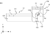
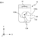
- the first member 12 rotates around the rotation axis AX in a state where the protruding portion 122 is engaged with the notch portion 133 of the second member 13. Although the details will be described later, the position where the first member 12 is in contact with the first surface 133a of the edge of the notch portion 133 and the position where the first member 12 is in contact with the second surface 133b of the edge of the notch portion 133. Rotates around the axis of rotation AX between. Further, the first member 12 is formed with a through hole into which the fastening member 14 is inserted, and the fastening member 14 inserted into the through hole is fixed to the cover 11 to fix the first member 12 to the cover 11. Will be done.
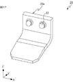
- the first member 12 preferably has a plate-shaped mounting portion 121 and a plate-shaped protruding portion 122. Further, it is preferable that the first member 12 has an extension portion 123 that is continuous with the attachment portion 121 and extends in a direction away from the main surface 11a of the cover 11. In this case, the first member 12 may be supported by the second member 13 coming into contact with the lower surface of the stretched portion 123 in the vertical direction.
- the first member 12 includes an extension portion 123 whose main surface is orthogonal to the rotation axis AX.
- the notch portion 133 is a notch having a shape extending in the positive direction of the Y axis and then extending in the positive direction of the X axis on the XY plane.
- the edge of the cutout portion 133 has a first surface 133a extending in the X-axis direction and a second surface 133b extending in the Y-axis direction.
- the first surface 133a and the second surface 133b are orthogonal to each other.
- the rotation range of the first member 12 is a range of 90 degrees between the position where the main surface of the first member 12 is parallel to the X axis and the position where the main surface of the first member 12 is parallel to the Y axis. Limited to.
- a part of the edge of the notch portion 133 is arcuate in the XY plane.
- FIG. 3 is a view of the first member 12 and the second member 13 at this time in the negative direction of the Z axis.
- the description of the housing 10 and the cover 11 is omitted in order to avoid complication of the drawing.
- the first member 12 rotates counterclockwise.
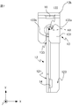
- An example of the state where the cover 11 is opened is shown in FIGS. 4 and 5. Note that in FIGS. 4 and 5, the description of the housing 10 and the cover 11 is omitted in order to avoid complication of the drawings.
- the first member 12 rotates counterclockwise around the rotation axis AX with the protruding portion 122 engaged with the notch portion 133. Specifically, the first member 12 rotates around the rotation axis AX in a state where the first surface 133a and the second surface 133b are in contact with a continuous portion.
- the cover 11 can be opened and closed only by the first member 12 and the second member 13.
- the first member 12 and the second member 13 do not require a rod-shaped shaft member unlike a conventional hinge, and therefore have a simple structure.
- the first member 12 and the second member 13 can be formed only by sheet metal processing, and the manufacturing process is simple because processing such as caulking and welding, which is required in the conventional manufacturing of hinges, is not required.
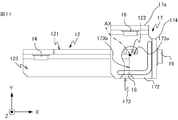
- the second member 17 shown in FIGS. 9 and 10 includes a first member support portion 171 that supports the first member 12, and a rotation range limiting portion 172 that has a shape that limits the rotation range of the first member 12. ..
- the rotation range limiting portion 172 has a notch portion 173 as in the first embodiment.
- the second member 17 includes a connecting portion 174 that is continuous with each of the first member support portion 171 and the rotation range limiting portion 172 and to which the movement limiting portion 18 is fixed.
- FIG. 11 shows a view of the first member 12 and the second member 17 at this time in the negative direction of the Z axis.
- the description of the housing 10 and the cover 11 is omitted in order to avoid complication of the drawing.
- the first member 12 rotates counterclockwise.
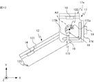
- An example of the state where the cover 11 is opened is shown in FIGS. 12 and 13. Note that in FIGS. 12 and 13, the description of the housing 10 and the cover 11 is omitted in order to avoid complication of the drawings.
- the first member 12 rotates counterclockwise around the rotation axis AX with the protruding portion 122 engaged with the notch portion 173.
- the first member 12 rotates counterclockwise and moves to the position shown in FIGS. 14 and 15.
- the description of the housing 10 and the cover 11 is omitted in order to avoid complication of the drawings.
- the first member 12 rotates counterclockwise around the rotation axis AX with the protruding portion 122 engaged with the notch portion 173.
- the first member 12 is in contact with the second surface 173b extending in the Y-axis direction of the edge of the notch 173 extending in the Y-axis direction. Therefore, the first member 12 cannot be further rotated counterclockwise from the states shown in FIGS. 14 and 15.
- the first member 12 can rotate about the rotation axis AX between the positions shown in FIGS. 8, 9 and 11 and the positions shown in FIGS. 14 and 15. Specifically, the first surface 173a extending in the X-axis direction of the edge of the notch 173 and the second surface 173b extending in the Y-axis direction of the edge of the notch 173 make the rotation range of the first member 12 90. Limit to the degree. As a result, the cover 11 to which the first member 12 is fixed rotates around the rotation axis AX within a range of 90 degrees and can be opened and closed.
- the vehicle-mounted device 3 includes a cover support portion 20 that supports the cover 11 in a state where the cover 11 is closed.
- the number and mounting position of the first member 12 and the second members 13, 17 included in the in-vehicle device 1-3 can be arbitrarily determined according to the material, weight, and the like of the cover 11.
- the method of fixing the first member 12 to the cover 11 is not limited to the method of using the fastening member 14, and is arbitrary.
- the first member 12 may be fixed to the cover 11 by welding.
- the first member 12 may be fixed to the cover 11 in a state of being in direct contact with the main surface 11a of the cover 11, or may be fixed to the cover 11 in a state of sandwiching another member between the first member 12 and the main surface 11a. May be done.
- the method of fixing the second members 13 and 17 to the housing 10 is not limited to the method of using the fastening members 15 and 16, and is arbitrary.
- the second members 13 and 17 may be fixed to the housing 10 by welding.
- the second members 13 and 17 may be fixed to the housing 10 in a state of being in direct contact with the housing 10, or may be fixed to the housing 10 with another member sandwiched between the second members 13 and 17 and the housing 10. It may be fixed.
- the first surface 133a and the second surface 133b may be continuous as in the above-described embodiment, or may be continuous via other members. The same applies to the first surface 134a and the second surface 134b, and the first surface 173a and the second surface 173b.
- An example of the case where the first surface 134a and the second surface 134b are continuous via another member is shown in FIG. As shown in FIG. 21, the first surface 134a and the second surface 134b may be smoothly connected by a curved surface. In FIG.
- the description of the rotation axis AX is omitted in order to show the shape of the rotation range limiting portion 132, but the rotation axis AX corresponds to the straight line corresponding to the first surface 134a and the second surface 134b on the XY plane. It passes through the curved part that connects with the straight line.
- the direction in which the rotation axis AX extends is not limited to the Z-axis direction, and may extend in a direction intersecting the Z-axis.
Landscapes
- Engineering & Computer Science (AREA)
- Mechanical Engineering (AREA)
- Power Engineering (AREA)
- Automation & Control Theory (AREA)
- Transportation (AREA)
- Pivots And Pivotal Connections (AREA)
- Casings For Electric Apparatus (AREA)
- General Engineering & Computer Science (AREA)
Priority Applications (4)
| Application Number | Priority Date | Filing Date | Title |
|---|---|---|---|
| PCT/JP2019/043623 WO2021090430A1 (ja) | 2019-11-07 | 2019-11-07 | 車載機器 |
| JP2021554493A JP7170900B2 (ja) | 2019-11-07 | 2019-11-07 | 車載機器 |
| DE112019007873.9T DE112019007873B4 (de) | 2019-11-07 | 2019-11-07 | Bordeinrichtung |
| US17/770,101 US12344285B2 (en) | 2019-11-07 | 2019-11-07 | In-vehicle device |
Applications Claiming Priority (1)
| Application Number | Priority Date | Filing Date | Title |
|---|---|---|---|
| PCT/JP2019/043623 WO2021090430A1 (ja) | 2019-11-07 | 2019-11-07 | 車載機器 |
Publications (1)
| Publication Number | Publication Date |
|---|---|
| WO2021090430A1 true WO2021090430A1 (ja) | 2021-05-14 |
Family
ID=75848827
Family Applications (1)
| Application Number | Title | Priority Date | Filing Date |
|---|---|---|---|
| PCT/JP2019/043623 Ceased WO2021090430A1 (ja) | 2019-11-07 | 2019-11-07 | 車載機器 |
Country Status (4)
| Country | Link |
|---|---|
| US (1) | US12344285B2 (https=) |
| JP (1) | JP7170900B2 (https=) |
| DE (1) | DE112019007873B4 (https=) |
| WO (1) | WO2021090430A1 (https=) |
Families Citing this family (1)
| Publication number | Priority date | Publication date | Assignee | Title |
|---|---|---|---|---|
| USD853970S1 (en) * | 2017-02-10 | 2019-07-16 | Eaton Intelligent Power Limited | Electrical apparatus with a line side isolation safety switch |
Citations (3)
| Publication number | Priority date | Publication date | Assignee | Title |
|---|---|---|---|---|
| JPS3930928Y1 (https=) * | 1962-10-15 | 1964-10-20 | ||
| JPS4996447A (https=) * | 1973-01-24 | 1974-09-12 | ||
| JPH03125496A (ja) * | 1989-10-09 | 1991-05-28 | Fujitsu Ltd | 回動扉の着脱構造 |
Family Cites Families (19)
| Publication number | Priority date | Publication date | Assignee | Title |
|---|---|---|---|---|
| DE7013777U (de) | 1970-04-15 | 1970-08-13 | Saba Schwarswilder App Bau Ans | Scharnier fuer deckel von gehaeusen fuer ten- und bildwiedergabegeraete wie z.b. schallplattenabspiel- tonband- und video-geraete |
| US3889992A (en) * | 1973-11-23 | 1975-06-17 | Shur Lok Manufacturing Co Inc | Latch assembly |
| US4378948A (en) * | 1976-06-15 | 1983-04-05 | Reliance Products Corporation | Safety closure latch |
| US4717184A (en) * | 1985-06-10 | 1988-01-05 | Phil Boyce | Safety latch for drawers and the like |
| US4715628A (en) * | 1985-11-21 | 1987-12-29 | Brink Satya S | Child resistant cabinet lock combination finger lock |
| CH677244A5 (https=) * | 1988-07-05 | 1991-04-30 | Von Roll Ag | |
| US4881298A (en) * | 1988-07-21 | 1989-11-21 | General Motors Corporation | Separable door hinge for vehicle body |
| US5054723A (en) * | 1990-04-19 | 1991-10-08 | Augustine Medical, Inc. | Hinged tube support |
| US5008975A (en) * | 1990-06-08 | 1991-04-23 | Wang Rong W | Hinge device |
| US6173593B1 (en) * | 1999-04-02 | 2001-01-16 | Christopher John Liermann | Concealed locking mechanism and method for use with drawers or cabinet doors or the like |
| DE10021899C1 (de) * | 2000-05-08 | 2001-12-13 | Draeger Medical Ag | Scharnier für einen Behälter |
| JP4576361B2 (ja) | 2006-08-02 | 2010-11-04 | 日本車輌製造株式会社 | 車両 |
| FR2940986B1 (fr) * | 2009-01-15 | 2011-01-07 | Saint Gobain Pont A Mousson | Ensemble d'articulation et dispositif de voirie correspondant |
| JP5444395B2 (ja) | 2012-03-06 | 2014-03-19 | タキゲン製造株式会社 | 扉の掛金装置 |
| JP5925386B2 (ja) * | 2013-04-24 | 2016-05-25 | 三菱電機株式会社 | 車両用制御装置 |
| CN207253260U (zh) * | 2017-03-01 | 2018-04-20 | 张仲智 | 一种烤炉盖简易铰链 |
| TWM553440U (zh) * | 2017-08-08 | 2017-12-21 | 連展科技股份有限公司 | 機架式箱體 |
| US11932287B2 (en) | 2018-03-23 | 2024-03-19 | Mitsubishi Electric Corporation | Control device for railway vehicle |
| US10851570B2 (en) * | 2018-06-29 | 2020-12-01 | Austin Hardware And Supply, Inc. | Interlocking hinge |
-
2019
- 2019-11-07 DE DE112019007873.9T patent/DE112019007873B4/de active Active
- 2019-11-07 WO PCT/JP2019/043623 patent/WO2021090430A1/ja not_active Ceased
- 2019-11-07 US US17/770,101 patent/US12344285B2/en active Active
- 2019-11-07 JP JP2021554493A patent/JP7170900B2/ja active Active
Patent Citations (3)
| Publication number | Priority date | Publication date | Assignee | Title |
|---|---|---|---|---|
| JPS3930928Y1 (https=) * | 1962-10-15 | 1964-10-20 | ||
| JPS4996447A (https=) * | 1973-01-24 | 1974-09-12 | ||
| JPH03125496A (ja) * | 1989-10-09 | 1991-05-28 | Fujitsu Ltd | 回動扉の着脱構造 |
Also Published As
| Publication number | Publication date |
|---|---|
| JPWO2021090430A1 (https=) | 2021-05-14 |
| DE112019007873T5 (de) | 2022-09-01 |
| DE112019007873B4 (de) | 2023-07-06 |
| JP7170900B2 (ja) | 2022-11-14 |
| US12344285B2 (en) | 2025-07-01 |
| US20220389954A1 (en) | 2022-12-08 |
Similar Documents
| Publication | Publication Date | Title |
|---|---|---|
| CN118774510A (zh) | 冷藏库的铰链结构 | |
| JP5366650B2 (ja) | 電気機器収納用キャビネット | |
| WO2021090430A1 (ja) | 車載機器 | |
| CN116111533A (zh) | 电连接箱 | |
| JP7132278B2 (ja) | 電気接続箱 | |
| US20160037919A1 (en) | Secure Rack-Based Storage Enclosure | |
| CN101317123A (zh) | 显示装置 | |
| WO2018079327A1 (ja) | 端末装置 | |
| CN114026753A (zh) | 配电柜及电力转换装置 | |
| JP3062727B2 (ja) | 開閉蓋取付構造 | |
| WO2013059318A2 (en) | Double hinge assembly | |
| JP3225003B2 (ja) | カバー付きケース | |
| JP7766554B2 (ja) | 錠装置 | |
| JPH06296088A (ja) | 電子機器 | |
| WO2025052532A1 (ja) | 電子機器 | |
| JP6388970B2 (ja) | 携帯用情報機器 | |
| JPS6338646Y2 (https=) | ||
| JPS5927109Y2 (ja) | プリント配線基板収納装置 | |
| JPWO2019180918A1 (ja) | 鉄道車両用制御装置 | |
| KR200140922Y1 (ko) | 버스의 사이드 엔진도어용 힌지 | |
| JP3185919B2 (ja) | 電磁遮蔽ロッカー | |
| JPH0632985U (ja) | 庫内扉板開閉機構 | |
| JP2025187285A (ja) | スイッチギヤ | |
| JPH056702Y2 (https=) | ||
| JP2690273B2 (ja) | 点検口装置 |
Legal Events
| Date | Code | Title | Description |
|---|---|---|---|
| 121 | Ep: the epo has been informed by wipo that ep was designated in this application |
Ref document number: 19951579 Country of ref document: EP Kind code of ref document: A1 |
|
| ENP | Entry into the national phase |
Ref document number: 2021554493 Country of ref document: JP Kind code of ref document: A |
|
| 122 | Ep: pct application non-entry in european phase |
Ref document number: 19951579 Country of ref document: EP Kind code of ref document: A1 |
|
| WWG | Wipo information: grant in national office |
Ref document number: 17770101 Country of ref document: US |