WO2021085487A1 - 非水電解液二次電池、これに用いるセパレータ、及び非水電解液二次電池の製造方法 - Google Patents
非水電解液二次電池、これに用いるセパレータ、及び非水電解液二次電池の製造方法 Download PDFInfo
- Publication number
- WO2021085487A1 WO2021085487A1 PCT/JP2020/040485 JP2020040485W WO2021085487A1 WO 2021085487 A1 WO2021085487 A1 WO 2021085487A1 JP 2020040485 W JP2020040485 W JP 2020040485W WO 2021085487 A1 WO2021085487 A1 WO 2021085487A1
- Authority
- WO
- WIPO (PCT)
- Prior art keywords
- secondary battery
- separator
- electrolyte secondary
- aqueous electrolyte
- heat
- Prior art date
- Legal status (The legal status is an assumption and is not a legal conclusion. Google has not performed a legal analysis and makes no representation as to the accuracy of the status listed.)
- Ceased
Links
Images


Classifications
-
- H—ELECTRICITY
- H01—ELECTRIC ELEMENTS
- H01M—PROCESSES OR MEANS, e.g. BATTERIES, FOR THE DIRECT CONVERSION OF CHEMICAL ENERGY INTO ELECTRICAL ENERGY
- H01M50/00—Constructional details or processes of manufacture of the non-active parts of electrochemical cells other than fuel cells, e.g. hybrid cells
- H01M50/40—Separators; Membranes; Diaphragms; Spacing elements inside cells
- H01M50/409—Separators, membranes or diaphragms characterised by the material
- H01M50/449—Separators, membranes or diaphragms characterised by the material having a layered structure
-
- H—ELECTRICITY
- H01—ELECTRIC ELEMENTS
- H01M—PROCESSES OR MEANS, e.g. BATTERIES, FOR THE DIRECT CONVERSION OF CHEMICAL ENERGY INTO ELECTRICAL ENERGY
- H01M10/00—Secondary cells; Manufacture thereof
- H01M10/05—Accumulators with non-aqueous electrolyte
- H01M10/056—Accumulators with non-aqueous electrolyte characterised by the materials used as electrolytes, e.g. mixed inorganic/organic electrolytes
- H01M10/0564—Accumulators with non-aqueous electrolyte characterised by the materials used as electrolytes, e.g. mixed inorganic/organic electrolytes the electrolyte being constituted of organic materials only
- H01M10/0566—Liquid materials
- H01M10/0569—Liquid materials characterised by the solvents
-
- H—ELECTRICITY
- H01—ELECTRIC ELEMENTS
- H01M—PROCESSES OR MEANS, e.g. BATTERIES, FOR THE DIRECT CONVERSION OF CHEMICAL ENERGY INTO ELECTRICAL ENERGY
- H01M10/00—Secondary cells; Manufacture thereof
- H01M10/05—Accumulators with non-aqueous electrolyte
- H01M10/052—Li-accumulators
-
- H—ELECTRICITY
- H01—ELECTRIC ELEMENTS
- H01M—PROCESSES OR MEANS, e.g. BATTERIES, FOR THE DIRECT CONVERSION OF CHEMICAL ENERGY INTO ELECTRICAL ENERGY
- H01M10/00—Secondary cells; Manufacture thereof
- H01M10/05—Accumulators with non-aqueous electrolyte
- H01M10/052—Li-accumulators
- H01M10/0525—Rocking-chair batteries, i.e. batteries with lithium insertion or intercalation in both electrodes; Lithium-ion batteries
-
- H—ELECTRICITY
- H01—ELECTRIC ELEMENTS
- H01M—PROCESSES OR MEANS, e.g. BATTERIES, FOR THE DIRECT CONVERSION OF CHEMICAL ENERGY INTO ELECTRICAL ENERGY
- H01M10/00—Secondary cells; Manufacture thereof
- H01M10/05—Accumulators with non-aqueous electrolyte
- H01M10/058—Construction or manufacture
- H01M10/0585—Construction or manufacture of accumulators having only flat construction elements, i.e. flat positive electrodes, flat negative electrodes and flat separators
-
- H—ELECTRICITY
- H01—ELECTRIC ELEMENTS
- H01M—PROCESSES OR MEANS, e.g. BATTERIES, FOR THE DIRECT CONVERSION OF CHEMICAL ENERGY INTO ELECTRICAL ENERGY
- H01M10/00—Secondary cells; Manufacture thereof
- H01M10/42—Methods or arrangements for servicing or maintenance of secondary cells or secondary half-cells
- H01M10/4235—Safety or regulating additives or arrangements in electrodes, separators or electrolyte
-
- H—ELECTRICITY
- H01—ELECTRIC ELEMENTS
- H01M—PROCESSES OR MEANS, e.g. BATTERIES, FOR THE DIRECT CONVERSION OF CHEMICAL ENERGY INTO ELECTRICAL ENERGY
- H01M50/00—Constructional details or processes of manufacture of the non-active parts of electrochemical cells other than fuel cells, e.g. hybrid cells
- H01M50/40—Separators; Membranes; Diaphragms; Spacing elements inside cells
- H01M50/403—Manufacturing processes of separators, membranes or diaphragms
-
- H—ELECTRICITY
- H01—ELECTRIC ELEMENTS
- H01M—PROCESSES OR MEANS, e.g. BATTERIES, FOR THE DIRECT CONVERSION OF CHEMICAL ENERGY INTO ELECTRICAL ENERGY
- H01M50/00—Constructional details or processes of manufacture of the non-active parts of electrochemical cells other than fuel cells, e.g. hybrid cells
- H01M50/40—Separators; Membranes; Diaphragms; Spacing elements inside cells
- H01M50/409—Separators, membranes or diaphragms characterised by the material
-
- H—ELECTRICITY
- H01—ELECTRIC ELEMENTS
- H01M—PROCESSES OR MEANS, e.g. BATTERIES, FOR THE DIRECT CONVERSION OF CHEMICAL ENERGY INTO ELECTRICAL ENERGY
- H01M50/00—Constructional details or processes of manufacture of the non-active parts of electrochemical cells other than fuel cells, e.g. hybrid cells
- H01M50/40—Separators; Membranes; Diaphragms; Spacing elements inside cells
- H01M50/409—Separators, membranes or diaphragms characterised by the material
- H01M50/411—Organic material
- H01M50/414—Synthetic resins, e.g. thermoplastics or thermosetting resins
-
- H—ELECTRICITY
- H01—ELECTRIC ELEMENTS
- H01M—PROCESSES OR MEANS, e.g. BATTERIES, FOR THE DIRECT CONVERSION OF CHEMICAL ENERGY INTO ELECTRICAL ENERGY
- H01M50/00—Constructional details or processes of manufacture of the non-active parts of electrochemical cells other than fuel cells, e.g. hybrid cells
- H01M50/40—Separators; Membranes; Diaphragms; Spacing elements inside cells
- H01M50/409—Separators, membranes or diaphragms characterised by the material
- H01M50/411—Organic material
- H01M50/414—Synthetic resins, e.g. thermoplastics or thermosetting resins
- H01M50/417—Polyolefins
-
- H—ELECTRICITY
- H01—ELECTRIC ELEMENTS
- H01M—PROCESSES OR MEANS, e.g. BATTERIES, FOR THE DIRECT CONVERSION OF CHEMICAL ENERGY INTO ELECTRICAL ENERGY
- H01M50/00—Constructional details or processes of manufacture of the non-active parts of electrochemical cells other than fuel cells, e.g. hybrid cells
- H01M50/40—Separators; Membranes; Diaphragms; Spacing elements inside cells
- H01M50/409—Separators, membranes or diaphragms characterised by the material
- H01M50/443—Particulate material
-
- H—ELECTRICITY
- H01—ELECTRIC ELEMENTS
- H01M—PROCESSES OR MEANS, e.g. BATTERIES, FOR THE DIRECT CONVERSION OF CHEMICAL ENERGY INTO ELECTRICAL ENERGY
- H01M50/00—Constructional details or processes of manufacture of the non-active parts of electrochemical cells other than fuel cells, e.g. hybrid cells
- H01M50/40—Separators; Membranes; Diaphragms; Spacing elements inside cells
- H01M50/409—Separators, membranes or diaphragms characterised by the material
- H01M50/449—Separators, membranes or diaphragms characterised by the material having a layered structure
- H01M50/451—Separators, membranes or diaphragms characterised by the material having a layered structure comprising layers of only organic material and layers containing inorganic material
-
- H—ELECTRICITY
- H01—ELECTRIC ELEMENTS
- H01M—PROCESSES OR MEANS, e.g. BATTERIES, FOR THE DIRECT CONVERSION OF CHEMICAL ENERGY INTO ELECTRICAL ENERGY
- H01M50/00—Constructional details or processes of manufacture of the non-active parts of electrochemical cells other than fuel cells, e.g. hybrid cells
- H01M50/40—Separators; Membranes; Diaphragms; Spacing elements inside cells
- H01M50/409—Separators, membranes or diaphragms characterised by the material
- H01M50/449—Separators, membranes or diaphragms characterised by the material having a layered structure
- H01M50/457—Separators, membranes or diaphragms characterised by the material having a layered structure comprising three or more layers
-
- H—ELECTRICITY
- H01—ELECTRIC ELEMENTS
- H01M—PROCESSES OR MEANS, e.g. BATTERIES, FOR THE DIRECT CONVERSION OF CHEMICAL ENERGY INTO ELECTRICAL ENERGY
- H01M50/00—Constructional details or processes of manufacture of the non-active parts of electrochemical cells other than fuel cells, e.g. hybrid cells
- H01M50/40—Separators; Membranes; Diaphragms; Spacing elements inside cells
- H01M50/46—Separators, membranes or diaphragms characterised by their combination with electrodes
-
- H—ELECTRICITY
- H01—ELECTRIC ELEMENTS
- H01M—PROCESSES OR MEANS, e.g. BATTERIES, FOR THE DIRECT CONVERSION OF CHEMICAL ENERGY INTO ELECTRICAL ENERGY
- H01M50/00—Constructional details or processes of manufacture of the non-active parts of electrochemical cells other than fuel cells, e.g. hybrid cells
- H01M50/40—Separators; Membranes; Diaphragms; Spacing elements inside cells
- H01M50/489—Separators, membranes, diaphragms or spacing elements inside the cells, characterised by their physical properties, e.g. swelling degree, hydrophilicity or shut down properties
-
- H—ELECTRICITY
- H01—ELECTRIC ELEMENTS
- H01M—PROCESSES OR MEANS, e.g. BATTERIES, FOR THE DIRECT CONVERSION OF CHEMICAL ENERGY INTO ELECTRICAL ENERGY
- H01M50/00—Constructional details or processes of manufacture of the non-active parts of electrochemical cells other than fuel cells, e.g. hybrid cells
- H01M50/40—Separators; Membranes; Diaphragms; Spacing elements inside cells
- H01M50/489—Separators, membranes, diaphragms or spacing elements inside the cells, characterised by their physical properties, e.g. swelling degree, hydrophilicity or shut down properties
- H01M50/491—Porosity
-
- Y—GENERAL TAGGING OF NEW TECHNOLOGICAL DEVELOPMENTS; GENERAL TAGGING OF CROSS-SECTIONAL TECHNOLOGIES SPANNING OVER SEVERAL SECTIONS OF THE IPC; TECHNICAL SUBJECTS COVERED BY FORMER USPC CROSS-REFERENCE ART COLLECTIONS [XRACs] AND DIGESTS
- Y02—TECHNOLOGIES OR APPLICATIONS FOR MITIGATION OR ADAPTATION AGAINST CLIMATE CHANGE
- Y02E—REDUCTION OF GREENHOUSE GAS [GHG] EMISSIONS, RELATED TO ENERGY GENERATION, TRANSMISSION OR DISTRIBUTION
- Y02E60/00—Enabling technologies; Technologies with a potential or indirect contribution to GHG emissions mitigation
- Y02E60/10—Energy storage using batteries
-
- Y—GENERAL TAGGING OF NEW TECHNOLOGICAL DEVELOPMENTS; GENERAL TAGGING OF CROSS-SECTIONAL TECHNOLOGIES SPANNING OVER SEVERAL SECTIONS OF THE IPC; TECHNICAL SUBJECTS COVERED BY FORMER USPC CROSS-REFERENCE ART COLLECTIONS [XRACs] AND DIGESTS
- Y02—TECHNOLOGIES OR APPLICATIONS FOR MITIGATION OR ADAPTATION AGAINST CLIMATE CHANGE
- Y02P—CLIMATE CHANGE MITIGATION TECHNOLOGIES IN THE PRODUCTION OR PROCESSING OF GOODS
- Y02P70/00—Climate change mitigation technologies in the production process for final industrial or consumer products
- Y02P70/50—Manufacturing or production processes characterised by the final manufactured product
Definitions
- the present invention relates to a non-aqueous electrolyte secondary battery, a separator used for the non-aqueous electrolyte secondary battery, and a method for manufacturing the non-aqueous electrolyte secondary battery.
- Non-aqueous electrolyte secondary batteries represented by lithium-ion secondary batteries have high energy density, excellent storage performance, low-temperature operability, etc., and are widely used in portable electronic devices such as mobile phones and laptop computers. There is. In addition, the size of batteries has been increased so that they can be used in transportation equipment such as automobiles, and they are also being used as storage devices for nighttime electric power and electric power generated by natural energy power generation.
- Patent Document 1 states that in a lithium ion battery, a thermal expansion (sex) capsule is added to a separator infiltrated with an electrolytic solution arranged between a positive electrode and a negative electrode.
- a thermal expansion (sex) capsule is added to a separator infiltrated with an electrolytic solution arranged between a positive electrode and a negative electrode.
- the thermally expandable capsule expands when the battery temperature rises, and a space without an electrolytic solution is formed in the separator arranged between the electrodes to physically shut out the movement of lithium ions.
- Patent Document 2 contains a gas generating agent on the surface or inside of at least one of the positive electrode active material layer, the electrolyte layer, and the negative electrode active material layer, and the temperature of the secondary battery reaches 60 ° C. or higher and lower than 300 ° C.
- a non-aqueous electrolyte secondary battery characterized in that gas is generated from the gas generating agent is described, and a 1H-tetrazole (gas generating agent) sandwiched between two separators is used instead of the separator.
- the battery form that was used is also disclosed.
- the present inventors have made extensive studies in view of the above problems.
- a heat-expandable capsule is placed between two separators that are in close contact with each other by the action of the electrolytic solution.
- the heat-expandable capsule can be quickly expanded and shut down in a two-dimensional (planar) manner along the space between the two separators when the battery temperature rises. It was found that even if the thermal melting of the above progresses, it can be sufficiently maintained.
- a non-aqueous electrolyte secondary battery having a positive electrode, a negative electrode, and a composite separator arranged between the positive electrode and the negative electrode.
- the composite separator is a non-aqueous electrolyte secondary battery in which a heat-expandable capsule is sandwiched between layers of a laminate composed of at least two separator sheets.
- the thermal expansion start temperature of the thermal expansion capsule in the non-aqueous electrolyte secondary battery is 5 ° C. or more lower than the thermal melting temperature of the separator sheet sandwiching the thermal expansion capsule, according to [1].
- Non-aqueous electrolyte secondary battery is 5 ° C. or more lower than the thermal melting temperature of the separator sheet sandwiching the thermal expansion capsule.
- Secondary battery [5]
- the composite separator is any one of [1] to [4], wherein the ratio of the total area of the portion where the heat-expandable capsule is arranged to the total area of the composite separator is 50% or less in a plan view.
- [6] The non-aqueous electrolyte secondary battery according to any one of [1] to [5], wherein the composite separator is in a state of being pressurized in the stacking direction of the separator sheets in the non-aqueous electrolyte secondary battery.
- the separator sheet constituting the composite separator is a microporous film, and the separator sheets constituting the composite separator are in close contact with each other by the action of the electrolytic solution.
- the non-aqueous electrolyte secondary battery according to any one of [1] to [7], wherein the separator sheets are adhered to each other around and / or in the vicinity of the composite separator.
- a composite separator for a non-aqueous electrolyte secondary battery in which a heat-expandable capsule is sandwiched between layers of a laminate composed of at least two separator sheets.
- a method for producing a non-aqueous electrolyte secondary battery which comprises arranging the composite separator for a non-aqueous electrolyte secondary battery according to [9] between the positive electrode and the negative electrode.
- the numerical range represented by using “-” means a range including the numerical values before and after "-" as the lower limit value and the upper limit value.
- the “non-aqueous electrolytic solution” means an electrolytic solution that does not substantially contain water. That is, the “non-aqueous electrolytic solution” may contain a small amount of water as long as the effect of the present invention is not impaired.
- the “non-aqueous electrolytic solution” has a water concentration of 200 ppm (mass basis) or less, preferably 100 ppm or less, and more preferably 20 ppm or less.
- the "non-aqueous electrolyte secondary battery” broadly includes a secondary battery using a non-aqueous electrolyte.
- the non-aqueous electrolyte secondary battery of the present invention can quickly and more reliably shut down the movement of ions between the positive and negative electrodes when the battery temperature rises, even if the amount of the heat-expandable capsule used is suppressed, and it can be shut down at high temperatures. But this shutdown state can be sustained.
- the composite separator for a non-aqueous electrolyte secondary battery of the present invention is suitable as a separator for the non-aqueous electrolyte secondary battery of the present invention.
- the method for manufacturing a non-aqueous electrolyte secondary battery of the present invention even if the amount of the heat-expandable capsule used is suppressed, the exchange of ions between the positive and negative electrodes is quickly and more reliably shut down when the battery temperature rises. It is possible to obtain a non-aqueous electrolyte secondary battery capable of sustaining this shut-down state even at a high temperature.
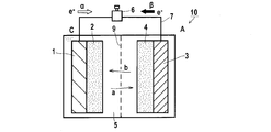
- FIG. 1 is an explanatory view (longitudinal sectional view) showing an operating mechanism of a lithium ion secondary battery, which is a form of a non-aqueous electrolyte secondary battery.
- FIG. 2 is a vertical cross-sectional view showing an example of a specific structure of a non-aqueous electrolyte secondary battery.
- FIG. 3 is an explanatory view (longitudinal sectional view) schematically showing a state of the composite separator arranged in the non-aqueous electrolytic solution secondary battery of the present invention.
- FIG. 1 is an explanatory view (longitudinal sectional view) showing an operating mechanism of a lithium ion secondary battery, which is a form of a non-aqueous electrolyte secondary battery.
- FIG. 2 is a vertical cross-sectional view showing an example of a specific structure of a non-aqueous electrolyte secondary battery.
- FIG. 3 is an explanatory view (longitudinal sectional view)
- FIG. 4 is an explanatory view (longitudinal sectional view) schematically showing a state in which the heat-expandable capsule of the composite separator is thermally expanded when the non-aqueous electrolyte secondary battery of the present invention is exposed to a high temperature.
- FIG. 5 is a vertical cross-sectional view schematically showing the structure of a lamicelle battery, which is a non-aqueous electrolyte secondary battery produced in the examples.
- the non-aqueous electrolytic solution secondary battery of the present invention has a positive electrode, a negative electrode, and a composite separator arranged between the positive electrode and the negative electrode.
- This composite separator is a laminate composed of at least two separator sheets, and a heat-expandable capsule is sandwiched between layers of the laminate.
- the composite separator is a laminate of three or more separator sheets, the laminate has two or more layers.
- the heat-expandable capsule may be present between any layers. That is, the heat-expandable capsule may be present between one of the two or more layers, or the heat-expandable capsule may be present between the two or more layers.
- the constituent materials of the plurality of separator sheets constituting one composite separator may be the same or different. From the viewpoint of thinning the obtained non-aqueous electrolytic solution secondary battery, it is preferable that the number of separator sheets constituting the composite separator is two.
- FIG. 1 is an explanatory diagram (conceptual diagram) showing an operating mechanism of a lithium ion secondary battery, which is a form of a non-aqueous electrolyte secondary battery.
- the lithium ion secondary battery 10 is capable of inserting and releasing or dissolving and precipitating a non-aqueous electrolyte solution 5, a positive electrode C (positive electrode current collector 1, positive electrode active material layer 2) capable of inserting and releasing lithium ions, and lithium ions.
- a negative electrode A negative electrode current collector 3, negative electrode active material layer 4) is provided.
- a separator 9 is arranged between the positive electrode C and the negative electrode A.
- ⁇ electrons (e ⁇ ) are supplied from the positive electrode side to the negative electrode side via the circuit wiring 7, and lithium ions are emitted from the positive electrode active material layer 2.
- This lithium ion moves to the negative electrode side through the non-aqueous electrolytic solution 5 and is accumulated in the negative electrode active material layer (a).
- ⁇ lithium ions accumulated in the negative electrode active material layer are released, and these lithium ions are accumulated in the positive electrode active material layer through the non-aqueous electrolytic solution 5 (b), and at the same time via the circuit wiring 7.
- Electrons are supplied to the operating mechanism 6. This is the operating mechanism of the lithium-ion secondary battery.
- the operating mechanism of the non-aqueous electrolyte secondary battery has been conceptually described by taking a lithium ion secondary battery as an example.
- a specific shape of the non-aqueous electrolyte secondary battery will be described.
- Specific battery shapes of the non-aqueous electrolyte secondary battery include a bottomed tubular shape, a bottomed square shape, a thin shape, a sheet shape, a paper shape, and the like.
- the secondary battery may have any shape as long as it functions as a battery by the above-mentioned operating mechanism. Further, it may be a variant such as a horseshoe shape or a comb shape in consideration of the shape of the system or device to be incorporated.
- FIG. 2 is an example of a bottomed tubular non-aqueous electrolyte secondary battery 100.
- This battery is a bottomed tubular non-aqueous electrolysis battery in which a positive electrode sheet 14 and a negative electrode sheet 16 stacked via a separator 12 are wound and stored in an outer can 18 (the outer can 18 also serves as a negative electrode current collector). It is a liquid secondary battery 100.
- 20 in the figure is an insulating plate
- 22 is a sealing plate
- 24 is a positive electrode current collector
- 26 is a gasket
- 28 is a pressure sensitive valve body
- 30 is a current blocking element.
- the hatching is changed in consideration of visibility, but each member corresponds to the overall view by a code.
- Each material, electrolytic solution, member, etc. used in the non-aqueous electrolytic solution secondary battery of the present invention is not particularly limited except for the structure of the separator. As these materials, members and the like, those used for ordinary non-aqueous electrolyte secondary batteries can be appropriately applied. Further, as for the method for producing the non-aqueous electrolytic solution secondary battery of the present invention, a normal method can be appropriately adopted except for the configuration of the separator. For example, Japanese Patent Application Laid-Open No. 2016-201308, Japanese Patent Application Laid-Open No. 2008-226807, and the like can be appropriately referred to.
- the composite separator which is a characteristic configuration of the non-aqueous electrolyte secondary battery of the present invention, will be described below.
- the composite separator used in the non-aqueous electrolyte secondary battery of the present invention is a laminate composed of at least two separator sheets, and a heat-expandable capsule is sandwiched between the layers of the laminate. There is.
- the composite separator used in the present invention has holes like a normal separator used in a non-aqueous electrolyte secondary battery, and in a normal battery use state, it insulates between the positive and negative electrodes while allowing the electrolytic solution and ions to permeate. Functions as a positive / negative electrode separation membrane.
- the composite separator of the present invention when the battery temperature rises due to some kind of battery abnormality, a normal separator is thermally melted, and the thermal melting closes the vacancies and blocks the ion conduction between the positive and negative electrodes to function the battery.
- the heat-expandable capsule When stopped, in the composite separator of the present invention, the heat-expandable capsule rapidly thermally expands prior to the thermal melting of the separator, and the exchange of ions between the positive and negative electrodes is shut down more quickly and more reliably. In addition, this shutdown state can be maintained even under high temperature.
- the form in which the composite separator used in the present invention has a heat-expandable capsule sandwiched between layers of a laminate composed of two separator sheets will be described below. However, the composite separator used in the present invention is not limited to these forms except as specified in the present invention.
- FIG. 3 is a vertical cross-sectional view schematically showing one form of a composite separator in a state of being arranged in the non-aqueous electrolyte secondary battery of the present invention.
- the composite separator 40 has a structure in which two separator sheets 41 and 42 are laminated, and a heat-expandable capsule 43 is sandwiched between layers of the laminated body.
- the two separator sheets 41 and 42 are usually microporous membranes (microporous membranes) and are in close contact with each other due to the action of the electrolytic solution. That is, in the separator sheet infiltrated with the electrolytic solution, the electrolytic solution acts like an adhesive, and the separator sheets adhere to each other in a laminated state.
- the composite separator infiltrated with the electrolytic solution is in a state where the two separator sheets 41 and 42 are in close contact with each other by the action of the electrolytic solution in the portion where the heat-expandable capsule 43 is not arranged. is there.
- the constituent materials of the two separator sheets 41 and 42 may be the same or different.
- the composite separator 40 arranged in the state shown in FIG. 3 has two separator sheets 41 and 42 along the interface when the battery temperature rises above a predetermined temperature. It expands dimensionally.
- the state after this thermal expansion is schematically shown in FIG.
- the composite separator of the non-aqueous electrolyte secondary battery of the present invention creates a state in which there is no electrolyte between the laminated separator sheets when the battery temperature rises for some reason. Stop the battery function.
- the thermal expansion start temperature (foaming start temperature in the atmosphere (1 atm)) of the heat-expandable capsule is higher than the heat-melting temperature of the separator sheet sandwiching the heat-expandable capsule. It is preferably low, and more preferably 5 ° C. or more lower than the thermal melting temperature of the separator sheet. With such a relationship, it is possible to quickly and more reliably shut down the movement of ions between the positive and negative electrodes when the battery temperature rises.
- the thermal expansion start temperature of the thermally expandable capsule is usually 70 to 140 ° C., preferably 70 to 120 ° C.
- the hot melting temperature of the separator sheet is usually 120 to 160 ° C, preferably 120 to 130 ° C.
- the thermal expansion start temperature of the thermal expansion capsule is a temperature at which the volume of the thermal expansion capsule expands more than twice under 1 atm (1 atm) due to thermal expansion.
- the hot melting temperature of the separator sheet is synonymous with the melting point of the constituent material of the separator sheet.
- the melting point of the material having the lowest melting point is defined as the thermal melting temperature of the separator sheet in relation to the thermal expansion start temperature of the heat-expandable capsule.
- the particle size of the heat-expandable capsule constituting the composite separator is preferably larger than the pore size of the separator sheet sandwiching the heat-expandable capsule, and the heat-expandable capsule of the heat-expandable capsule.
- the particle size is more preferably 1.5 times or more the pore size of the separator sheet that sandwiches the heat-expandable capsule.
- the layers of the laminate in which the separator sheets are in close contact with each other are expanded two-dimensionally (in the plane direction) so that the expanding heat-expandable capsule cuts through the layers, and the state where there is no electrolytic solution in the heat generating portion and its surroundings is quickly obtained. Can be created.
- the non-aqueous electrolytic solution secondary battery usually applies a constant pressure (usually “atmospheric pressure” + “0.05 to 0.1 MPa") in the stacking direction of the composite separator, it is thermally expandable.
- the capsule does not easily expand in the stacking direction of the separator sheet.
- the above-mentioned "particle size of the heat-expandable capsule” is the average particle size of the heat-expandable capsule used.
- the "particle size of the heat-expandable capsule” shall be the volume-based median diameter (d50).
- the "hole diameter of the separator sheet” 20 holes (entrances of holes) observed on the surface of the separator sheet are randomly observed using an electron microscope, and each of the 20 holes on the surface of the separator sheet is observed. For each, the maximum value of the hole width in the direction perpendicular to the maximum radial direction is measured, and the 20 measured values are arithmetically averaged.
- the "maximum diameter" of a hole means this distance when the distance from one point on the inner circumference of the hole on the surface of the separator sheet to another point on the inner circumference is maximum.
- the pore size of the separator sheet is determined in a state where the separator sheet is dried.
- the particle size of the heat-expandable capsule used in the present invention is preferably 1 to 20 ⁇ m, more preferably 1 to 15 ⁇ m, and even more preferably 1 to 12 ⁇ m. Further, the particle size may be 1 to 10 ⁇ m, may be 1 to 5 ⁇ m, and is preferably 1 to 3 ⁇ m.
- the pore size of the separator sheet is preferably 1 ⁇ m or less. For example, it can be 0.01 to 1 ⁇ m, may be 0.01 to 0.8 ⁇ m, preferably 0.01 to 0.5 ⁇ m, more preferably 0.02 to 0.2 ⁇ m, and 0.03 to 0. .1 ⁇ m is more preferable.
- a separator sheet constituting the composite separator a separator usually used in a non-aqueous electrolyte secondary battery can be used without particular limitation as long as the effect of the present invention is not impaired.
- the constituent material of the separator sheet include a porous polymer material, an inorganic material, an organic-inorganic hybrid material, and glass fiber.
- the volume ratio occupied by the gaps in the separator sheet, that is, the porosity is preferably 20% to 90%, more preferably 35% to 80%.
- Examples of the polymer material include cellulose non-woven fabric, polyethylene, polypropylene and the like, and a separator sheet in which these are used in combination can also be used. It is also preferable to laminate two or more kinds of microporous films having different pore diameters, porosities, pore closing temperatures, and the like.
- Examples of the inorganic material include oxides such as alumina and silicon dioxide; nitrides such as aluminum nitride and silicon nitride; and sulfates such as barium sulfate and calcium sulfate.
- the heat-expandable capsule is usually formed of a thermoplastic resin containing a foaming agent inside.
- the foaming agent is not particularly limited as long as it expands at a target temperature.
- Chemical foaming agents; as well as physical foaming agents such as butane, pentane, hexane, dichloroethane, dichloromethane, freon, air, carbonate gas, nitrogen gas and the like.
- the thermally expandable capsule used in the present invention is preferably one that expands in volume when the internal pressure becomes sufficient to expand the capsule due to vaporization of the low boiling point liquid inside.
- a method of controlling the temperature of volume expansion it can be controlled by selecting a liquid whose boiling point is close to a target temperature as the low boiling point liquid to be sealed inside.
- a known method such as a core selvation method can be adopted for forming the capsule.
- heat-expandable capsule examples include Expanders 051DU, 007WU, 053WU, 053DU, 054WU, 091DU, 091-080DU, 091-140-DU, 092-120DU, 093-120DU, 820WU, 642WU manufactured by Nippon Ferrite Co., Ltd. , 551WU, 551DU, 551-20WU, 551-20DU, 551-80WU, 551-80DU, 461WU, 461DU, 461-20; Microcapsules F-20, F-30, F-40, manufactured by Matsumoto Oil & Fat Co., Ltd.
- F-50, F-80S, F-82, F-85, F-100, FN-100 SSD and the like are commercially available. These are composed of an outer shell of a copolymer and a foaming agent composed of a low boiling point hydrocarbon inside the outer shell, and when a predetermined temperature between about 70 ° C. and 200 ° C. is reached, the outer shell portion of the outer shell portion. Due to softening and vaporization of the contents, its own volume expands to, for example, about 40 to 60 times.
- the thermal expansion start temperature is higher in the electrolytic solution of the non-aqueous electrolytic solution secondary battery (in the electrolytic solution arranged under 1 atm) than the measured value in the atmosphere (1 atm). ) Is preferably 10 ° C. or higher.
- the thermal expansion response to the rise in battery temperature is enhanced, and it becomes possible to shut down more quickly when a battery abnormality occurs.
- the thermal expansion start temperature drops in the electrolytic solution of the above-mentioned non-aqueous electrolytic solution secondary battery, the cause is the polarity contained in the electrolytic solution when the thermal expansion microcapsules are immersed in the non-aqueous electrolytic solution. It is conceivable that the solvent will plasticize the capsule wall. The lower the boiling point of the polar solvent contained in the electrolytic solution, the more the decrease in the thermal expansion start temperature tends to become more apparent.
- the total ratio of the area of the portion where the heat-expandable capsule is arranged (the area of the heat-expandable capsule horizontally projected onto the separator sheet) to the total area of the composite separator is , 50% or less is preferable.
- this ratio is preferably as small as the range in which the effect of the present invention is exhibited, more preferably 40% or less, further preferably 30% or less, and may be 20% or less.
- the non-aqueous electrolyte secondary battery of the present invention capable of two-dimensionally controlling the thermal expansion of the heat-expandable capsule can realize a quick shutdown effect. ..
- the composite separator used in the present invention is preferably in a form in which the separator sheets are adhered to each other around and / or in the vicinity of the composite separator.
- Adhesion between the separator sheets can be performed by applying heat sealing or the like, and it is preferable to apply heat sealing or the like linearly along the periphery of the composite separator.
- the composite separator has been described with respect to a state in which it is arranged between the positive electrode and the negative electrode of the non-aqueous electrolyte secondary battery.
- the above-mentioned composite separator can be independently distributed as a composite separator for a non-aqueous electrolyte secondary battery in a state before being incorporated into the non-aqueous electrolyte secondary battery. That is, according to the present invention, there is provided a composite separator for a non-aqueous electrolyte secondary battery in which a heat-expandable capsule is sandwiched between layers of a laminate composed of at least two separator sheets.
- the composite separator for a non-aqueous electrolytic solution secondary battery may be in a dry state without being infiltrated with an electrolytic solution or the like, or may be in a wet state by being infiltrated with an electrolytic solution or the like.
- the size of the composite separator for the non-aqueous electrolyte secondary battery of the present invention is not particularly limited. When a large-sized composite separator is produced and incorporated into a non-aqueous electrolyte secondary battery, it can be cut into a desired size and used.
- the composite separator of the present invention can be produced by dispersing (sprinkling) heat-expandable capsules substantially uniformly between desired layers when at least two separator sheets are superposed. It is also preferable that after forming a laminate of separator sheets formed by arranging heat-expandable capsules between desired layers, the separator sheets are adhered to each other around and / or in the vicinity thereof. For example, a heat seal having a width of 1 to 10 mm can be applied along the periphery of the composite separator to bond adjacent separator sheets to each other along the periphery of the composite separator.
- a non-aqueous electrolyte secondary battery can be manufactured using the composite sheet of the present invention. That is, according to the present invention, there is provided a method for manufacturing a non-aqueous electrolyte secondary battery, which comprises arranging the composite separator for the non-aqueous electrolyte secondary battery of the present invention between the positive electrode and the negative electrode. The arrangement of the composite separator for the non-aqueous electrolyte secondary battery between the positive electrode and the negative electrode can be performed in the same manner as the arrangement of the separator in the normal non-aqueous electrolyte secondary battery.
- the non-aqueous electrolyte secondary battery of the present invention includes, for example, a notebook computer, a pen input computer, a mobile computer, an electronic book player, a mobile phone, a cordless phone slave unit, a pager, a handy terminal, a mobile fax, a mobile copy, a mobile printer, and the like.
- a non-aqueous electrolytic solution was prepared by dissolving LiPF 6 as a lithium salt at a concentration of 1 M in a non-aqueous solvent containing 40% by mass of ethylene carbonate and 60% by mass of ethyl methyl carbonate.
- positive electrode active material layer forming material 85% by mass of lithium nickel manganate (LiNi 0.5 Mn 1.5 O 4 ) as the positive electrode active material, 7% by mass of carbon black as the conductive auxiliary agent, and 8% by mass of PVDF (polyvinylidene fluoride) as the binder.
- the composition to be contained was prepared and used as a positive electrode active material layer forming material.
- Matsumoto Microsphere-FN-100 SSD manufactured by Matsumoto Yushi Pharmaceutical Co., Ltd., the thermal expansion start temperature is 120 to 130 ° C in the atmosphere (under 1 atm), the average particle size is 6 to 6 to 11 ⁇ m (value published by the manufacturer) was sprinkled substantially uniformly and arranged in a single layer to prepare a composite separator composed of a heat-expandable capsule and two separator sheets sandwiching the same.
- the ratio of the total area of the portion where the heat-expandable capsules were arranged to the total area of the composite separator was 40 to 48%.
- the obtained composite separator was used in the non-aqueous electrolyte secondary battery of Example 2. Further, the obtained composite separator was heat-sealed with a width of 5 mm on four sides around the composite separator using a heat sealer, and used in the non-aqueous electrolyte secondary battery of Example 1. Further, two separator sheets were laminated without sandwiching the heat-expandable capsule, and the four sides around the laminate were heat-sealed with a width of 5 mm, which was used for the non-aqueous electrolyte secondary battery of the comparative example. The production of the non-aqueous electrolyte secondary battery will be described below.
- the laminated cell battery (Lamicelle battery) shown in FIG. 5 was produced as follows (FIG. 5 schematically shows a form in which the composite separator has a heat-expandable capsule).
- the positive electrode active material layer forming material was applied onto an aluminum current collector foil (length 3.8 cm ⁇ width 5.3 cm ⁇ thickness 80 ⁇ m), dried and pressed to prepare a positive electrode.
- the negative electrode active material layer forming material was applied onto a copper current collector foil (length 4 cm ⁇ width 5.5 cm ⁇ thickness 80 ⁇ m), dried and pressed to prepare a negative electrode.
- the battery With the composite separator sandwiched between the positive electrode and the negative electrode, the battery was placed in a bag made of an Al laminated film, an electrolytic solution was injected, and the battery was vacuum-sealed to prepare a lamicelle battery.
- the obtained lamicelle battery was sandwiched between SUS plates (length 5 cm ⁇ width 7 cm ⁇ thickness 1 mm), restrained at atmospheric pressure + 0.05 MPa, and used in the following test.
- the shutdown function is exhibited even when the temperature rise is lower by using the composite separator of the present invention. It was also found that by sealing the periphery of the composite separator, the shutdown function begins to appear even in the low temperature range. Further, even if the hot melting state of the separator sheet progresses due to a high temperature (180 ° C. or higher) and the separator sheet itself cannot maintain a high shutdown state, the above-mentioned high temperature state can be obtained by using the composite separator of the present invention. So, I also found that the shutdown state can be further enhanced.
Landscapes
- Chemical & Material Sciences (AREA)
- Chemical Kinetics & Catalysis (AREA)
- Electrochemistry (AREA)
- General Chemical & Material Sciences (AREA)
- Engineering & Computer Science (AREA)
- Manufacturing & Machinery (AREA)
- Inorganic Chemistry (AREA)
- Materials Engineering (AREA)
- Physics & Mathematics (AREA)
- Condensed Matter Physics & Semiconductors (AREA)
- General Physics & Mathematics (AREA)
- Secondary Cells (AREA)
- Cell Separators (AREA)
Abstract
正極と、負極と、該正極と該負極との間に配された複合セパレータとを有する非水電解液二次電池であって、 上記複合セパレータは、少なくとも2枚のセパレータシートで構成された積層体の層間に熱膨張性カプセルを挟持してなる非水電解液二次電池、この非水電解液二次電池に好適な複合セパレータ、及びこの非水電解液二次電池の製造方法。
Description
本発明は、非水電解液二次電池、これに用いるセパレータ、及び非水電解液二次電池の製造方法に関する。
リチウムイオン二次電池に代表される非水電解液二次電池は、高エネルギー密度であり、貯蔵性能、低温動作性等にも優れ、携帯電話、ノートパソコン等のポータブル電子機器に広く利用されている。また、電池を大型化して、自動車をはじめとした輸送機器にも使用されるようになり、また夜間電力、自然エネルギー発電による電力等の貯蔵装置としての利用も進められている。
非水電解液二次電池は、電極中に含まれる不純物金属などが原因で内部短絡が生じると、電池の温度が局所的に上昇する。この局所的な温度上昇は、いわゆる熱暴走の引き金となる。
この熱暴走に対処する技術として、特許文献1には、リチウムイオン電池において、正極と負極との間に配される電解液に浸潤されたセパレータに、熱膨張(性)カプセルを添加することが記載されている。特許文献1記載の技術によれば、電池温度上昇時に熱膨張性カプセルが膨張し、電極間に配されたセパレータ内で電解液のない空間が形成されてリチウムイオンの移動を物理的にシャットアウトし、熱暴走を抑制できるとされる。
また、特許文献2には、正極活物質層、電解質層、及び負極活物質層の少なくとも1層の表面又は内部にガス発生剤を含み、二次電池の温度が60℃以上300℃未満に達したときに、ガス発生剤からガスが発生することを特徴とする非水電解質二次電池が記載され、1H-テトラゾール(ガス発生剤)を2枚のセパレータで挟持したものをセパレータの代わりに用いた電池形態も開示されている。特許文献2記載の技術によれば、非水電解質二次電池の温度が上昇した際にガス発生剤からガスが発生して拡散する。この拡散ガスが正極活物質層、セパレータ、負極活物質層などの空孔に入り込み、正極活物質層と負極活物質層との間を行き来するイオンの移動経路を狭めたり、遮断したりして内部抵抗を増大させて、さらなる温度上昇、過電流等の発生を抑えることができるとされる。
この熱暴走に対処する技術として、特許文献1には、リチウムイオン電池において、正極と負極との間に配される電解液に浸潤されたセパレータに、熱膨張(性)カプセルを添加することが記載されている。特許文献1記載の技術によれば、電池温度上昇時に熱膨張性カプセルが膨張し、電極間に配されたセパレータ内で電解液のない空間が形成されてリチウムイオンの移動を物理的にシャットアウトし、熱暴走を抑制できるとされる。
また、特許文献2には、正極活物質層、電解質層、及び負極活物質層の少なくとも1層の表面又は内部にガス発生剤を含み、二次電池の温度が60℃以上300℃未満に達したときに、ガス発生剤からガスが発生することを特徴とする非水電解質二次電池が記載され、1H-テトラゾール(ガス発生剤)を2枚のセパレータで挟持したものをセパレータの代わりに用いた電池形態も開示されている。特許文献2記載の技術によれば、非水電解質二次電池の温度が上昇した際にガス発生剤からガスが発生して拡散する。この拡散ガスが正極活物質層、セパレータ、負極活物質層などの空孔に入り込み、正極活物質層と負極活物質層との間を行き来するイオンの移動経路を狭めたり、遮断したりして内部抵抗を増大させて、さらなる温度上昇、過電流等の発生を抑えることができるとされる。
上記各特許文献に記載された熱膨張性カプセル及びガス発生剤は異物であり、通常時の電池性能の向上においては不利に働く。そのため、これらの使用量は極力抑えることが要求される。
しかし、特許文献1記載の方法では、熱膨張性カプセルの熱膨張方向を制御することができず、熱膨張性カプセルの使用量の低減と、シャットダウン機能の向上(シャットダウン機能の高速化、効率化等)との両立には制約がある。
また、特許文献2記載の技術では、ガス発生剤から生じたガスは電池内に制限なく拡散するため、シャットダウンには多量のガスが必要となり、シャットダウンの高速化にも制約がある。
さらに、特許文献1及び2のいずれの方法でも、電池が高温状態となりセパレータ自体の熱溶融が進行した場合には、形成されたシャットダウン状態を安定に維持することは難しい。
本発明は、熱膨張性カプセルの使用量を抑えても、電池温度上昇時に正負極間のイオンの行き来を、素早く、より確実にシャットダウンすることができ、高温下でもこのシャットダウン状態を持続することができる非水電解液二次電池、この非水電解液二次電池に好適な複合セパレータ、及びこの非水電解液二次電池の製造方法を提供することを課題とする。
しかし、特許文献1記載の方法では、熱膨張性カプセルの熱膨張方向を制御することができず、熱膨張性カプセルの使用量の低減と、シャットダウン機能の向上(シャットダウン機能の高速化、効率化等)との両立には制約がある。
また、特許文献2記載の技術では、ガス発生剤から生じたガスは電池内に制限なく拡散するため、シャットダウンには多量のガスが必要となり、シャットダウンの高速化にも制約がある。
さらに、特許文献1及び2のいずれの方法でも、電池が高温状態となりセパレータ自体の熱溶融が進行した場合には、形成されたシャットダウン状態を安定に維持することは難しい。
本発明は、熱膨張性カプセルの使用量を抑えても、電池温度上昇時に正負極間のイオンの行き来を、素早く、より確実にシャットダウンすることができ、高温下でもこのシャットダウン状態を持続することができる非水電解液二次電池、この非水電解液二次電池に好適な複合セパレータ、及びこの非水電解液二次電池の製造方法を提供することを課題とする。
本発明者らは上記課題に鑑み鋭意検討を重ねた。その結果、非水電解液二次電池において、正極活物質層と負極活物質層との間に配するセパレータとして、電解液の作用で互いに密着した2枚のセパレータの間に熱膨張性カプセルを挟持したものを採用することにより、電池温度上昇時には2枚のセパレータ間に沿って、二次元的(平面的)に、熱膨張性カプセルが素早く膨張してシャットダウンできること、このシャットダウン状態を、セパレータ自身の熱溶融が進行しても十分に維持できることを見い出した。さらに、上記の熱膨張性カプセルの膨張方向は二次元的に制御されるために、電池性能の向上には不利な異物である熱膨張性カプセルを少量としても、上記の効果が得られることも明らかとなってきた。
本発明はこれらの知見に基づきさらに検討を重ねて完成されるに至ったものである。
本発明はこれらの知見に基づきさらに検討を重ねて完成されるに至ったものである。
上記の課題は以下の手段により解決された。
〔1〕
正極と、負極と、正極と負極との間に配された複合セパレータとを有する非水電解液二次電池であって、
上記複合セパレータは、少なくとも2枚のセパレータシートで構成された積層体の層間に熱膨張性カプセルを挟持してなる、非水電解液二次電池。
〔2〕
上記非水電解液二次電池中において、上記熱膨張性カプセルの熱膨張開始温度が、熱膨張性カプセルを挟持する上記セパレータシートの熱溶融温度よりも5℃以上低い、〔1〕に記載の非水電解液二次電池。
〔3〕
上記熱膨張性カプセルの粒径が、熱膨張性カプセルを挟持する上記セパレータシートの孔径の1.5倍以上である、〔1〕又は〔2〕に記載の非水電解液二次電池。
〔4〕
上記熱膨張性カプセルの熱膨張開始温度が、大気中における測定値よりも、上記電解液中における測定値が10℃以上低い、〔1〕~〔3〕のいずれかに記載の非水電解液二次電池。
〔5〕
上記複合セパレータは、平面視において、複合セパレータ全体の面積に占める、熱膨張性カプセルが配された部分の面積の合計の割合が、50%以下である、〔1〕~〔4〕のいずれかに記載の非水電解液二次電池。
〔6〕
上記非水電解液二次電池において、上記複合セパレータは、セパレータシートの積層方向に加圧された状態にある、〔1〕~〔5〕のいずれかに記載の非水電解液二次電池。
〔7〕
上記非水電解液二次電池において、上記複合セパレータを構成するセパレータシートが微多孔膜であり、上記複合セパレータを構成するセパレータシート同士が電解液の作用により密着している、〔1〕~〔6〕のいずれかに記載の非水電解液二次電池。
〔8〕
上記複合セパレータの周囲及び/又はその近傍において、セパレータシート同士が接着されている、〔1〕~〔7〕のいずれかに記載の非水電解液二次電池。
〔9〕
少なくとも2枚のセパレータシートで構成された積層体の層間に熱膨張性カプセルを挟持してなる、非水電解液二次電池用複合セパレータ。
〔10〕
〔9〕に記載の非水電解液二次電池用複合セパレータを正極と負極との間に配することを含む、非水電解液二次電池の製造方法。
〔1〕
正極と、負極と、正極と負極との間に配された複合セパレータとを有する非水電解液二次電池であって、
上記複合セパレータは、少なくとも2枚のセパレータシートで構成された積層体の層間に熱膨張性カプセルを挟持してなる、非水電解液二次電池。
〔2〕
上記非水電解液二次電池中において、上記熱膨張性カプセルの熱膨張開始温度が、熱膨張性カプセルを挟持する上記セパレータシートの熱溶融温度よりも5℃以上低い、〔1〕に記載の非水電解液二次電池。
〔3〕
上記熱膨張性カプセルの粒径が、熱膨張性カプセルを挟持する上記セパレータシートの孔径の1.5倍以上である、〔1〕又は〔2〕に記載の非水電解液二次電池。
〔4〕
上記熱膨張性カプセルの熱膨張開始温度が、大気中における測定値よりも、上記電解液中における測定値が10℃以上低い、〔1〕~〔3〕のいずれかに記載の非水電解液二次電池。
〔5〕
上記複合セパレータは、平面視において、複合セパレータ全体の面積に占める、熱膨張性カプセルが配された部分の面積の合計の割合が、50%以下である、〔1〕~〔4〕のいずれかに記載の非水電解液二次電池。
〔6〕
上記非水電解液二次電池において、上記複合セパレータは、セパレータシートの積層方向に加圧された状態にある、〔1〕~〔5〕のいずれかに記載の非水電解液二次電池。
〔7〕
上記非水電解液二次電池において、上記複合セパレータを構成するセパレータシートが微多孔膜であり、上記複合セパレータを構成するセパレータシート同士が電解液の作用により密着している、〔1〕~〔6〕のいずれかに記載の非水電解液二次電池。
〔8〕
上記複合セパレータの周囲及び/又はその近傍において、セパレータシート同士が接着されている、〔1〕~〔7〕のいずれかに記載の非水電解液二次電池。
〔9〕
少なくとも2枚のセパレータシートで構成された積層体の層間に熱膨張性カプセルを挟持してなる、非水電解液二次電池用複合セパレータ。
〔10〕
〔9〕に記載の非水電解液二次電池用複合セパレータを正極と負極との間に配することを含む、非水電解液二次電池の製造方法。
本発明の説明において、「~」を用いて表される数値範囲は、「~」の前後に記載される数値を下限値及び上限値として含む範囲を意味する。
本発明において「非水電解液」とは、水を実質的に含まない電解液を意味する。すなわち、「非水電解液」は本発明の効果を妨げない範囲で微量の水を含んでいてもよい。本発明において「非水電解液」は、水の濃度が200ppm(質量基準)以下であり、100ppm以下が好ましく20ppm以下がより好ましい。なお、非水電解液を完全に無水とすることは現実的に困難であり、通常は水が1ppm以上含まれる。
本発明において「非水電解液二次電池」には、非水電解液を用いた二次電池が広く包含される。
本発明において「非水電解液」とは、水を実質的に含まない電解液を意味する。すなわち、「非水電解液」は本発明の効果を妨げない範囲で微量の水を含んでいてもよい。本発明において「非水電解液」は、水の濃度が200ppm(質量基準)以下であり、100ppm以下が好ましく20ppm以下がより好ましい。なお、非水電解液を完全に無水とすることは現実的に困難であり、通常は水が1ppm以上含まれる。
本発明において「非水電解液二次電池」には、非水電解液を用いた二次電池が広く包含される。
本発明の非水電解液二次電池は、熱膨張性カプセルの使用量を抑えても、電池温度上昇時に正負極間のイオンの行き来を、素早く、より確実にシャットダウンすることができ、高温下でもこのシャットダウン状態を持続することができる。また、本発明の非水電解液二次電池用複合セパレータは、本発明の非水電解液二次電池のセパレータとして好適である。また、本発明の非水電解液二次電池の製造方法によれば、熱膨張性カプセルの使用量を抑えても、電池温度上昇時に正負極間のイオンの行き来を素早く、より確実にシャットダウンすることができ、高温下でもこのシャットダウン状態を持続することができる非水電解液二次電池を得ることができる。
本発明の非水電解液二次電池の好ましい実施形態を説明するが、本発明は、本発明で規定すること以外は、これらの形態に限定されるものではない。
[非水電解液二次電池]
本発明の非水電解液二次電池は、正極と、負極と、正極と負極との間に配された複合セパレータとを有する。この複合セパレータは、少なくとも2枚のセパレータシートで構成された積層体であり、この積層体の層間には熱膨張性カプセルが挟持されている。
複合セパレータが3枚以上のセパレータシートの積層体の場合、この積層体は層間を2つ以上有する。この場合、熱膨張性カプセルはいずれの層間に存在していてもよい。すなわち、2つ以上の層間のうち1つの層間に熱膨張性カプセルが存在する形態でもよく、2つ以上の層間に熱膨張性カプセルが存在していてもよい。
1つの複合セパレータを構成する複数のセパレータシートの構成材料は、同一でもよく、異なってもよい。
得られる非水電解液二次電池の薄膜化の観点から、複合セパレータを構成するセパレータシートは2枚であることが好ましい。
本発明の非水電解液二次電池は、正極と、負極と、正極と負極との間に配された複合セパレータとを有する。この複合セパレータは、少なくとも2枚のセパレータシートで構成された積層体であり、この積層体の層間には熱膨張性カプセルが挟持されている。
複合セパレータが3枚以上のセパレータシートの積層体の場合、この積層体は層間を2つ以上有する。この場合、熱膨張性カプセルはいずれの層間に存在していてもよい。すなわち、2つ以上の層間のうち1つの層間に熱膨張性カプセルが存在する形態でもよく、2つ以上の層間に熱膨張性カプセルが存在していてもよい。
1つの複合セパレータを構成する複数のセパレータシートの構成材料は、同一でもよく、異なってもよい。
得られる非水電解液二次電池の薄膜化の観点から、複合セパレータを構成するセパレータシートは2枚であることが好ましい。
本発明の非水電解液二次電池は、セパレータの構成以外は、通常の非水電解液二次電池の構成を採用することができる。
図1は、非水電解液二次電池の一形態であるリチウムイオン二次電池の作動機構を示す説明図(概念図)である。リチウムイオン二次電池10は、非水電解液5と、リチウムイオンの挿入放出が可能な正極C(正極集電体1、正極活物質層2)と、リチウムイオンの挿入放出または溶解析出が可能な負極A(負極集電体3,負極活物質層4)とを備える。正極Cと負極Aの間にはセパレータ9が配される。このような電池構成とすることにより、充電(α)時には正極側から負極側へと回路配線7を介して電子(e-)が供給され、正極活物質層2からはリチウムイオンが放出されて、このリチウムイオンは非水電解液5を通じて負極側へと移動し、負極活物質層へと蓄積される(a)。また、放電(β)時には負極活物質層に蓄積されたリチウムイオンが放出されて、このリチウムイオンは非水電解液5を通じて正極活物質層へと蓄積され(b)、同時に回路配線7を介して動作機構6に電子が供給される。これが、リチウムイオン二次電池の作動機構である。
図1は、非水電解液二次電池の一形態であるリチウムイオン二次電池の作動機構を示す説明図(概念図)である。リチウムイオン二次電池10は、非水電解液5と、リチウムイオンの挿入放出が可能な正極C(正極集電体1、正極活物質層2)と、リチウムイオンの挿入放出または溶解析出が可能な負極A(負極集電体3,負極活物質層4)とを備える。正極Cと負極Aの間にはセパレータ9が配される。このような電池構成とすることにより、充電(α)時には正極側から負極側へと回路配線7を介して電子(e-)が供給され、正極活物質層2からはリチウムイオンが放出されて、このリチウムイオンは非水電解液5を通じて負極側へと移動し、負極活物質層へと蓄積される(a)。また、放電(β)時には負極活物質層に蓄積されたリチウムイオンが放出されて、このリチウムイオンは非水電解液5を通じて正極活物質層へと蓄積され(b)、同時に回路配線7を介して動作機構6に電子が供給される。これが、リチウムイオン二次電池の作動機構である。
上記ではリチウムイオン二次電池を例として非水電解液二次電池の作動機構を概念的に説明した。続いて非水電解液二次電池の具体的な形状について説明する。非水電解液二次電池の具体的な電池形状としては、有底筒型形状、有底角型形状、薄型形状、シート形状およびペーパー形状などが知られており、本発明の非水電解液二次電池は、上記作動機構により電池として機能すれば、いずれの形状であってもよい。また、組み込まれるシステム、機器等の形を考慮した馬蹄形や櫛型形状等の異型のものであってもよい。
図2は、有底筒型非水電解液二次電池100の一例である。この電池は、セパレータ12を介して重ね合わせた正極シート14、負極シート16を巻回して外装缶18(この外装缶18は負極集電体を兼ねる)内に収納した有底筒型非水電解液二次電池100となっている。その他、図中の20が絶縁板、22が封口板、24が正極集電体、26がガスケット、28が圧力感応弁体、30が電流遮断素子である。なお、拡大した円内の図示は視認性を考慮しハッチングを変えているが、各部材は符号により全体図と対応している。
図2は、有底筒型非水電解液二次電池100の一例である。この電池は、セパレータ12を介して重ね合わせた正極シート14、負極シート16を巻回して外装缶18(この外装缶18は負極集電体を兼ねる)内に収納した有底筒型非水電解液二次電池100となっている。その他、図中の20が絶縁板、22が封口板、24が正極集電体、26がガスケット、28が圧力感応弁体、30が電流遮断素子である。なお、拡大した円内の図示は視認性を考慮しハッチングを変えているが、各部材は符号により全体図と対応している。
本発明の非水電解液二次電池に用いる各材料、電解液、部材等は、セパレータの構成を除いて特に制限されない。これらの材料、部材等は、通常の非水電解液二次電池に用いられるものを適宜に適用することができる。また、本発明の非水電解液二次電池の作製方法についても、セパレータの構成を除いては、通常の方法を適宜に採用することができる。例えば、特開2016-201308号公報、特開2008-226807号公報等を適宜に参照することができる。
本発明の非水電解液二次電池の特徴的な構成である複合セパレータについて以下に説明する。
本発明の非水電解液二次電池の特徴的な構成である複合セパレータについて以下に説明する。
<複合セパレータ>
本発明の非水電解液二次電池に用いる複合セパレータは、上記の通り、少なくとも2枚のセパレータシートで構成された積層体であり、この積層体の層間には熱膨張性カプセルが挟持されている。本発明に用いる複合セパレータは、非水電解液二次電池に用いる通常のセパレータと同様、空孔を有し、通常の電池の使用状態では電解液及びイオンを透過しながら正負極間を絶縁する正負極分離膜として機能する。また、何らかの電池異常が生じて電池温度が上昇した際には、通常のセパレータであれば熱溶融し、この熱溶融により空孔を閉塞して正負極間のイオン伝導を遮断して電池機能を停止するところ、本発明の複合セパレータは、セパレータの熱溶融に先んじて熱膨張性カプセルが素早く熱膨張し、正負極間のイオンの行き来を、素早く、より確実にシャットダウンする。また、高温下でもこのシャットダウン状態を持続することができる。
本発明に用いる複合セパレータが、2枚のセパレータシートからなる積層体の層間に熱膨張性カプセルを挟持した形態について以下に説明する。ただし、本発明に用いる複合セパレータは、本発明で規定すること以外はこれらの形態に限定されるものではない。
本発明の非水電解液二次電池に用いる複合セパレータは、上記の通り、少なくとも2枚のセパレータシートで構成された積層体であり、この積層体の層間には熱膨張性カプセルが挟持されている。本発明に用いる複合セパレータは、非水電解液二次電池に用いる通常のセパレータと同様、空孔を有し、通常の電池の使用状態では電解液及びイオンを透過しながら正負極間を絶縁する正負極分離膜として機能する。また、何らかの電池異常が生じて電池温度が上昇した際には、通常のセパレータであれば熱溶融し、この熱溶融により空孔を閉塞して正負極間のイオン伝導を遮断して電池機能を停止するところ、本発明の複合セパレータは、セパレータの熱溶融に先んじて熱膨張性カプセルが素早く熱膨張し、正負極間のイオンの行き来を、素早く、より確実にシャットダウンする。また、高温下でもこのシャットダウン状態を持続することができる。
本発明に用いる複合セパレータが、2枚のセパレータシートからなる積層体の層間に熱膨張性カプセルを挟持した形態について以下に説明する。ただし、本発明に用いる複合セパレータは、本発明で規定すること以外はこれらの形態に限定されるものではない。
図3は、本発明の非水電解液二次電池に配された状態の複合セパレータの一形態を模式的に示す縦断面図である。図3に示すように、複合セパレータ40は、2枚のセパレータシート41、42が積層された構成を有し、この積層体の層間には熱膨張性カプセル43が挟持されている。2枚のセパレータシート41、42は、通常は微多孔質の膜(微多孔膜)であり、電解液の作用で密着している。すなわち、電解液に浸潤したセパレータシートは、電解液が接着剤のように作用して、積層状態でセパレータシート同士が密着する。これは、たとえるなら、ティッシュペーパーに水を吸わせると密着性が高まる現象と同じである。したがって、非水電解液二次電池において、電解液に浸潤した複合セパレータは、熱膨張性カプセル43が配されていない部分において2枚のセパレータシート41、42が電解液の作用で密着した状態にある。なお、2枚のセパレータシート41、42の構成材料は同一でもよく、異なってもよい。
本発明の非水電解液二次電池において図3に示す状態で配された複合セパレータ40は、電池温度が所定温度以上にまで上昇すると、2枚のセパレータシート41、42の界面に沿って二次元的に膨張する。この熱膨張後の状態を図4に模式的に示す。図4に示すように、本発明の非水電解液二次電池が有する複合セパレータは、何らかの原因で電池温度が上昇した際に、積層されたセパレータシートの間に電解液のない状態を作り出し、電池機能を停止する。
本発明の非水電解液二次電池において、熱膨張性カプセルの熱膨張開始温度(大気中(1気圧)における発泡開始温度)は、熱膨張性カプセルを挟持するセパレータシートの熱溶融温度よりも低いことが好ましく、セパレータシートの熱溶融温度よりも5℃以上低いことがより好ましい。このような関係とすることにより、電池温度上昇時に正負極間のイオンの行き来を、素早く、より確実にシャットダウンすることができる。熱膨張性カプセルの上記熱膨張開始温度は、通常は70~140℃であり、70~120℃が好ましい。また、セパレータシートの熱溶融温度は通常は120~160℃であり、120~130℃が好ましい。
ここで、熱膨張性カプセルの熱膨張開始温度とは、熱膨張により熱膨張性カプセルの体積が、1気圧(1atm)下で、2倍以上に膨張する温度である。また、セパレータシートの熱溶融温度とは、セパレータシートの構成材料の融点と同義である。セパレータシートの構成材料が2種以上の場合、上記の熱膨張性カプセルの熱膨張開始温度との関係については、最も融点の低い材料の融点を、セパレータシートの熱溶融温度とする。
ここで、熱膨張性カプセルの熱膨張開始温度とは、熱膨張により熱膨張性カプセルの体積が、1気圧(1atm)下で、2倍以上に膨張する温度である。また、セパレータシートの熱溶融温度とは、セパレータシートの構成材料の融点と同義である。セパレータシートの構成材料が2種以上の場合、上記の熱膨張性カプセルの熱膨張開始温度との関係については、最も融点の低い材料の融点を、セパレータシートの熱溶融温度とする。
本発明の非水電解液二次電池において、複合セパレータを構成する熱膨張性カプセルの粒径は、この熱膨張性カプセルを挟持するセパレータシートの孔径よりも大きいことが好ましく、熱膨張性カプセルの粒径は熱膨張性カプセルを挟持するセパレータシートの孔径の1.5倍以上であることがより好ましい。このような関係とすることにより、熱膨張性カプセルがセパレータシート内に入り込みにくく、熱膨張性カプセルが熱膨張した際に、その膨張方向を、積層されたセパレータシート同士の界面に沿った方向へとより確実に制御できる。つまり、セパレータシート同士が密着した積層体の層間を、膨張する熱膨張性カプセルが層間を切り開くように二次元的(平面方向)に膨張し、発熱部位とその周辺に電解液がない状態を素早く作り出すことができる。なお、非水電解液二次電池は、複合セパレータの積層方向には通常、一定の圧(通常は「大気圧」+「0.05~0.1MPa」)がかかっているため、熱膨張性カプセルはセパレータシートの積層方向には膨張しにくい。
上記の「熱膨張性カプセルの粒径」は、使用する熱膨張性カプセルの平均粒子径である。この平均粒子径は、熱膨張性カプセルの製造メーカーないし販売メーカーが公表している。メーカー公表の平均粒子径が不明の場合には、「熱膨張性カプセルの粒径」は体積基準のメディアン径(d50)とする。
また、「セパレータシートの孔径」は、セパレータシートを、電子顕微鏡を用いてその表面に観察される20個の孔(孔の入口)を無作為に観察し、セパレータシート表面における20個の各孔それぞれについて、最大径方向に対して垂直方向の孔の幅の最大値を測定し、20個の測定値を算術平均した値とする。孔の「最大径」とは、セパレータシート表面における孔の内周のある一点から、この内周の他の点までの距離が最大となるとき、この距離を意味する。セパレータシートの孔径は、セパレータシートを乾燥させた状態で行う。
上記の「熱膨張性カプセルの粒径」は、使用する熱膨張性カプセルの平均粒子径である。この平均粒子径は、熱膨張性カプセルの製造メーカーないし販売メーカーが公表している。メーカー公表の平均粒子径が不明の場合には、「熱膨張性カプセルの粒径」は体積基準のメディアン径(d50)とする。
また、「セパレータシートの孔径」は、セパレータシートを、電子顕微鏡を用いてその表面に観察される20個の孔(孔の入口)を無作為に観察し、セパレータシート表面における20個の各孔それぞれについて、最大径方向に対して垂直方向の孔の幅の最大値を測定し、20個の測定値を算術平均した値とする。孔の「最大径」とは、セパレータシート表面における孔の内周のある一点から、この内周の他の点までの距離が最大となるとき、この距離を意味する。セパレータシートの孔径は、セパレータシートを乾燥させた状態で行う。
本発明に用いる熱膨張性カプセルの粒径は、1~20μmが好ましく、1~15μmがより好ましく、1~12μmがさらに好ましい。また、この粒径は1~10μmでもよく、1~5μmでもよく、1~3μmとすることも好ましい。また、セパレータシートの孔径は、1μm以下が好ましい。例えば、0.01~1μmとすることができ、0.01~0.8μmとしてもよく、0.01~0.5μmが好ましく、0.02~0.2μmがより好ましく、0.03~0.1μmがさらに好ましい。
続いて、本発明に用いる複合セパレータの構成材料について、好ましい形態を説明する。
<セパレータシート>
複合セパレータを構成するセパレータシートとしては、非水電解液二次電池において通常用いられるセパレータを、本発明の効果を損なわない範囲で特に制限なく用いることができる。例えば、セパレータシートの構成材料として、多孔質のポリマー材料、無機材料、有機無機ハイブリッド材料またはガラス繊維などが挙げられる。セパレータシートの隙間の占める体積比率、すなわち気孔率は、20%~90%が好ましく、35%~80%がより好ましい。
複合セパレータを構成するセパレータシートとしては、非水電解液二次電池において通常用いられるセパレータを、本発明の効果を損なわない範囲で特に制限なく用いることができる。例えば、セパレータシートの構成材料として、多孔質のポリマー材料、無機材料、有機無機ハイブリッド材料またはガラス繊維などが挙げられる。セパレータシートの隙間の占める体積比率、すなわち気孔率は、20%~90%が好ましく、35%~80%がより好ましい。
上記ポリマー材料としては、例えば、セルロース不織布、ポリエチレン、ポリプロピレンなどが挙げられ、これらを併用したセパレータシートを用いることもできる。孔径、気孔率や孔の閉塞温度などを変えた2種以上の微多孔フィルムを積層したものも好ましい。
上記無機材料としては、例えば、アルミナ、二酸化珪素等の酸化物; 窒化アルミ、窒化珪素等の窒化物; 硫酸バリウム、硫酸カルシウム等の硫酸塩が挙げられる。
上記無機材料としては、例えば、アルミナ、二酸化珪素等の酸化物; 窒化アルミ、窒化珪素等の窒化物; 硫酸バリウム、硫酸カルシウム等の硫酸塩が挙げられる。
<熱膨張性カプセル>
熱膨張性カプセルは、通常は、内部に発泡剤を含んだ熱可塑性樹脂で形成されている。発泡剤は目的の温度で膨張すれば特に制限されない。例えば、アゾ化合物、ニトロソ化合物、ヒドラジン誘導体、セミカルバジド化合物、テトラゾール化合物、イソシアネート化合物、重炭酸塩、炭酸塩、亜硝酸塩、水素化物、重炭酸ナトリウムと酸、過酸化水素とイースト菌、亜鉛粉末と酸などの化学発泡剤;並びに、ブタン、ペンタン、ヘキサン、ジクロルエタン、ジクロルメタン、フロン、空気、炭酸ガス、窒素ガスなどの物理発泡剤が挙げられる。
本発明に用いる熱膨張性カプセルは、内部の低沸点液体が気化すること等により、内部圧力がカプセルを膨張させるのに充分な圧力となることで体積膨張するものが好ましい。体積膨張する温度を制御する方法としては、内部に封入する低沸点液体として、その沸点が目的の温度付近の液体を選択することにより制御できる。また、体積膨張をより素早く進行させるために、カプセルの外殻部分を所定温度以下に軟化点をもつ熱可塑性樹脂等により形成することも好ましい。カプセルの形成は、コアセルベーション法等の公知の方法等が採用できる。
熱膨張性カプセルは、通常は、内部に発泡剤を含んだ熱可塑性樹脂で形成されている。発泡剤は目的の温度で膨張すれば特に制限されない。例えば、アゾ化合物、ニトロソ化合物、ヒドラジン誘導体、セミカルバジド化合物、テトラゾール化合物、イソシアネート化合物、重炭酸塩、炭酸塩、亜硝酸塩、水素化物、重炭酸ナトリウムと酸、過酸化水素とイースト菌、亜鉛粉末と酸などの化学発泡剤;並びに、ブタン、ペンタン、ヘキサン、ジクロルエタン、ジクロルメタン、フロン、空気、炭酸ガス、窒素ガスなどの物理発泡剤が挙げられる。
本発明に用いる熱膨張性カプセルは、内部の低沸点液体が気化すること等により、内部圧力がカプセルを膨張させるのに充分な圧力となることで体積膨張するものが好ましい。体積膨張する温度を制御する方法としては、内部に封入する低沸点液体として、その沸点が目的の温度付近の液体を選択することにより制御できる。また、体積膨張をより素早く進行させるために、カプセルの外殻部分を所定温度以下に軟化点をもつ熱可塑性樹脂等により形成することも好ましい。カプセルの形成は、コアセルベーション法等の公知の方法等が採用できる。
熱膨張性カプセルとしては、例えば日本フェライト株式会社製のエクスパンセル051DU、007WU、053WU、053DU、054WU、091DU、091-080DU、091-140-DU、092-120DU、093-120DU、820WU、642WU、551WU、551DU、551-20WU、551-20DU、551-80WU、551-80DU、461WU、461DU、461-20; 松本油脂製株式会社製のマイクロカプセルF-20、F-30、F-40、F-50、F-80S、F-82、F-85、F-100、FN-100SSDなどが市販されている。これらは、共重合体の外殻と、その内部にある低沸点の炭化水素からなる発泡剤により構成されており、約70℃から200℃の間の所定の温度に達すると、外殻部分の軟化及び内容物の気化によって、自身の体積が、例えば40~60倍程度にまで膨張する。
本発明に用いる熱膨張性カプセルは、熱膨張開始温度が、大気中(1気圧)における測定値よりも、非水電解液二次電池の電解液中(1気圧下に配された電解液中)における測定値が10℃以上低いことが好ましい。これにより、非水電解液二次電池において、電池温度上昇に対する熱膨張応答性が高められ、電池異常が生じた際のシャットダウンを、より素早く行うことが可能となる。
上記の非水電解液二次電池の電解液中において熱膨張開始温度が低下する場合、その要因としては、非水電解液に熱膨張マイクロカプセルが浸漬された際に、電解液に含まれる極性溶媒がカプセル壁を可塑化することが考えられる。電解液に含まれる極性溶媒の沸点が低いほど、熱膨張開始温度の低下がより顕在化する傾向にある。
上記の非水電解液二次電池の電解液中において熱膨張開始温度が低下する場合、その要因としては、非水電解液に熱膨張マイクロカプセルが浸漬された際に、電解液に含まれる極性溶媒がカプセル壁を可塑化することが考えられる。電解液に含まれる極性溶媒の沸点が低いほど、熱膨張開始温度の低下がより顕在化する傾向にある。
本発明に用いる複合セパレータは、平面視において、複合セパレータ全体の面積に占める、熱膨張性カプセルが配された部分の面積(熱膨張性カプセルをセパレータシートに水平投影した面積)の合計の割合が、50%以下であることが好ましい。このように、熱膨張性カプセルをまばらに、事実上単層に、セパレータシートの間にまぶしても、本発明の目的の効果を得ることができる。また、この割合は、本発明の効果を奏する範囲で小さいほど好ましく、40%以下がより好ましく、30%以下がさらに好ましく、20%以下とすることもできる。このように熱膨張性カプセルの使用量を減らしても、熱膨張性カプセルの熱膨張を二次元的に制御できる本発明の非水電解液二次電池では、素早いシャットダウン効果を実現することができる。
本発明に用いる複合セパレータは、複合セパレータの周囲及び/又はその近傍において、セパレータシート同士が接着されている形態とすることが好ましい。このような形態とすることにより、熱膨張性カプセルが熱膨張した際などに外殻が破れてカプセルからガスが漏れた場合でも、セパレータシート同士の積層界面からのガスの散逸を遅らせることができ、シャットダウン状態のより安定的な維持にも寄与する。セパレータシート同士の接着は、ヒートシール等を施して行うことができ、複合セパレータの周囲に沿って、線状にヒートシール等を施すことが好ましい。
上記では、複合セパレータについて、非水電解液二次電池の正極と負極との間に配された状態に関して説明してきた。他方、上述した複合セパレータは、非水電解液二次電池用の複合セパレータとして、非水電解液二次電池に組み込む前の状態で独立して流通し得るものである。
すなわち、本発明によれば、少なくとも2枚のセパレータシートで構成された積層体の層間に熱膨張性カプセルを挟持してなる非水電解液二次電池用複合セパレータが提供される。この非水電解液二次電池用複合セパレータは、電解液等に浸潤させていない乾燥状態であってもよく、電解液等に浸潤させて湿潤状態にあってもよい。また、本発明の非水電解液二次電池用複合セパレータのサイズは特に制限されない。サイズの大きな複合セパレータを作製し、非水電解液二次電池に組み込む際に、所望のサイズに切り取り、使用することもできる。
すなわち、本発明によれば、少なくとも2枚のセパレータシートで構成された積層体の層間に熱膨張性カプセルを挟持してなる非水電解液二次電池用複合セパレータが提供される。この非水電解液二次電池用複合セパレータは、電解液等に浸潤させていない乾燥状態であってもよく、電解液等に浸潤させて湿潤状態にあってもよい。また、本発明の非水電解液二次電池用複合セパレータのサイズは特に制限されない。サイズの大きな複合セパレータを作製し、非水電解液二次電池に組み込む際に、所望のサイズに切り取り、使用することもできる。
本発明の複合セパレータは、少なくとも2枚のセパレータシートを重ね合せる際に、所望の層間に、熱膨張性カプセルを略均一に分散して(まぶして)配することにより製造することができる。
また、所望の層間に熱膨張性カプセルを配してなるセパレータシートの積層体を形成後、セパレータシート同士を、それらの周囲及び/又はその近傍において互いに接着することも好ましい。例えば、複合セパレータの周囲に沿って、1~10mm幅のヒートシールを施して、隣接するセパレータシート同士を、複合セパレータの周囲に沿って互いに接着することができる。
また、所望の層間に熱膨張性カプセルを配してなるセパレータシートの積層体を形成後、セパレータシート同士を、それらの周囲及び/又はその近傍において互いに接着することも好ましい。例えば、複合セパレータの周囲に沿って、1~10mm幅のヒートシールを施して、隣接するセパレータシート同士を、複合セパレータの周囲に沿って互いに接着することができる。
本発明の複合シートを用いて、非水電解液二次電池を製造することができる。すなわち本発明によれば、本発明の非水電解液二次電池用複合セパレータを正極と負極との間に配することを含む、非水電解液二次電池の製造方法が提供される。非水電解液二次電池用複合セパレータの、正極と負極との間への配設は、通常の非水電解液二次電池におけるセパレータの配設と同様にして行うことができる。
本発明の非水電解液二次電池は、例えば、ノートパソコン、ペン入力パソコン、モバイルパソコン、電子ブックプレーヤー、携帯電話、コードレスフォン子機、ページャー、ハンディーターミナル、携帯ファックス、携帯コピー、携帯プリンター、ヘッドフォンステレオ、ビデオムービー、液晶テレビ、ハンディークリーナー、ポータブルCD、ミニディスク、電気シェーバー、トランシーバー、電子手帳、電卓、メモリーカード、携帯テープレコーダー、ラジオ、バックアップ電源、メモリーカードなどの電子機器に搭載することができる。また、民生用として、自動車、電動車両、モーター、照明器具、玩具、ゲーム機器、ロードコンディショナー、時計、ストロボ、カメラ、医療機器(ペースメーカー、補聴器、肩もみ機など)などに搭載することができる。さらに、各種軍需用、宇宙用として用いることができる。また、太陽電池と組み合わせることもできる。
以下に、実施例に基づき本発明についてさらに詳細に説明する。なお、本発明がこれにより限定して解釈されるものではない。
[非水電解液の調製]
エチレンカーボネートを40質量%、エチルメチルカーボネートを60質量%含有する非水溶媒中に、リチウム塩としてLiPF6を1M濃度となるように溶解し、非水電解液を調製した。
エチレンカーボネートを40質量%、エチルメチルカーボネートを60質量%含有する非水溶媒中に、リチウム塩としてLiPF6を1M濃度となるように溶解し、非水電解液を調製した。
[正極活物質層形成材料の調製]
正極活物質としてニッケルマンガン酸リチウム(LiNi0.5Mn1.5O4)を85質量%、導電助剤としてカーボンブラックを7質量%、結着剤としてPVDF(ポリフッ化ビニリデン)を8質量%含有する組成物を調製し、正極活物質層形成材料とした。
正極活物質としてニッケルマンガン酸リチウム(LiNi0.5Mn1.5O4)を85質量%、導電助剤としてカーボンブラックを7質量%、結着剤としてPVDF(ポリフッ化ビニリデン)を8質量%含有する組成物を調製し、正極活物質層形成材料とした。
[負極活物質層形成材料の調製]
負極活物質としてGr(天然黒鉛)を92質量%、結着剤としてPVDFを8質量%含有する組成物を調製し、負極活物質層形成材料とした。
負極活物質としてGr(天然黒鉛)を92質量%、結着剤としてPVDFを8質量%含有する組成物を調製し、負極活物質層形成材料とした。
[複合セパレータ]
縦5cm×横6cm×厚み20μmのサイズで、孔径1μm以下、熱溶融温度が160℃のポリプロピレン製セパレータシート2枚を用意した。2枚のセパレータシート間に、熱膨張性カプセルとしてマツモトマイクロスフェア-FN-100SSD(松本油脂製薬社製、熱膨張開始温度が大気中(1気圧下)で120~130℃、平均粒子径6~11μm(メーカー公表値))を略均一にまぶして単層に配し、熱膨張性カプセルとそれを挟持する2枚のセパレータシートからなる複合セパレータを調製した。この複合セパレータは、平面視において、複合セパレータ全体の面積に占める、熱膨張性カプセルが配された部分の面積の合計の割合が、40~48%であった。
得られた複合セパレータを実施例2の非水電解液二次電池に用いた。また、得られた複合セパレータを、ヒートシーラーを用いてその周囲4辺を5mm幅でヒートシールしたものを実施例1の非水電解液二次電池に用いた。また、熱膨張性カプセルを挟持させずに2枚のセパレータシートを積層し、この積層体の周囲4辺を5mm幅でヒートシールしたものを比較例の非水電解液二次電池に用いた。非水電解液二次電池の作製について以下に説明する。
縦5cm×横6cm×厚み20μmのサイズで、孔径1μm以下、熱溶融温度が160℃のポリプロピレン製セパレータシート2枚を用意した。2枚のセパレータシート間に、熱膨張性カプセルとしてマツモトマイクロスフェア-FN-100SSD(松本油脂製薬社製、熱膨張開始温度が大気中(1気圧下)で120~130℃、平均粒子径6~11μm(メーカー公表値))を略均一にまぶして単層に配し、熱膨張性カプセルとそれを挟持する2枚のセパレータシートからなる複合セパレータを調製した。この複合セパレータは、平面視において、複合セパレータ全体の面積に占める、熱膨張性カプセルが配された部分の面積の合計の割合が、40~48%であった。
得られた複合セパレータを実施例2の非水電解液二次電池に用いた。また、得られた複合セパレータを、ヒートシーラーを用いてその周囲4辺を5mm幅でヒートシールしたものを実施例1の非水電解液二次電池に用いた。また、熱膨張性カプセルを挟持させずに2枚のセパレータシートを積層し、この積層体の周囲4辺を5mm幅でヒートシールしたものを比較例の非水電解液二次電池に用いた。非水電解液二次電池の作製について以下に説明する。
[非水電解液二次電池の作製]
図5に示すラミネート型セル電池(ラミセル電池)を下記の通り作製した(図5は、複合セパレータが熱膨張性カプセルを有する形態を模式的に示す。)。
上記正極活物質層形成材料を、アルミ集電箔(縦3.8cm×横5.3cm×厚み80μm)上に塗布し、乾燥後プレスして、正極を作製した。また、上記負極活物質層形成材料を、銅集電箔(縦4cm×横5.5cm×厚み80μm)上に塗布し、乾燥後プレスして、負極を作製した。上記複合セパレータを正極と負極との間に挟んだ状態で、Alラミネートフィルムで作製した袋にいれ、電解液を注入し、真空封止してラミセル電池を作製した。得られたラミセル電池をSUS板(縦5cm×横7cm×厚み1mm)で挟み、大気圧+0.05MPaで拘束し、下記試験に用いた。
図5に示すラミネート型セル電池(ラミセル電池)を下記の通り作製した(図5は、複合セパレータが熱膨張性カプセルを有する形態を模式的に示す。)。
上記正極活物質層形成材料を、アルミ集電箔(縦3.8cm×横5.3cm×厚み80μm)上に塗布し、乾燥後プレスして、正極を作製した。また、上記負極活物質層形成材料を、銅集電箔(縦4cm×横5.5cm×厚み80μm)上に塗布し、乾燥後プレスして、負極を作製した。上記複合セパレータを正極と負極との間に挟んだ状態で、Alラミネートフィルムで作製した袋にいれ、電解液を注入し、真空封止してラミセル電池を作製した。得られたラミセル電池をSUS板(縦5cm×横7cm×厚み1mm)で挟み、大気圧+0.05MPaで拘束し、下記試験に用いた。
[試験例] シャットダウン性能の評価
上記で作製した非水電解液二次電池(ラミセル電池)を用いて、電池温度上昇時にシャットダウン性能を下記のように評価した。
50℃に設定したホットプレート上に電池を静置し、ホットプレートの温度を5℃/分の昇温速度で上昇させながら、1kHzの交流法で内部抵抗を測定した。50℃の抵抗値(Ω)を「1」としたとき、温度上昇に伴う抵抗値の上昇率を調べた。
結果を下表に示す。
上記で作製した非水電解液二次電池(ラミセル電池)を用いて、電池温度上昇時にシャットダウン性能を下記のように評価した。
50℃に設定したホットプレート上に電池を静置し、ホットプレートの温度を5℃/分の昇温速度で上昇させながら、1kHzの交流法で内部抵抗を測定した。50℃の抵抗値(Ω)を「1」としたとき、温度上昇に伴う抵抗値の上昇率を調べた。
結果を下表に示す。

上記表に示されるように、本発明の複合セパレータを用いることにより、温度上昇がより低い状態でもシャットダウン機能が発現することがわかる。また、複合セパレータの周囲をシールしておくことにより、さらに低温域においてシャットダウン機能が発現し始めることもわかった。
また、高温(180℃以上)によってセパレータシートの熱溶融状態が進行してセパレータシート自体では高度なシャットダウン状態を維持できない状態となっても、本発明の複合セパレータを用いることにより、上記の高温状態で、むしろシャットダウン状態をさらに高めることができることもわかった。これは、2枚のセパレータシートの熱溶融状態がかなり進行しても、これらのシートはその間に挟まれて存在する熱膨張したカプセル(樹脂)ないしガスにより保持され、2枚の熱溶融セパレータシートと熱膨張したカプセルないしガスとが一体に作用して、安定的なシャットダウンに寄与しているものと推定される。
また、高温(180℃以上)によってセパレータシートの熱溶融状態が進行してセパレータシート自体では高度なシャットダウン状態を維持できない状態となっても、本発明の複合セパレータを用いることにより、上記の高温状態で、むしろシャットダウン状態をさらに高めることができることもわかった。これは、2枚のセパレータシートの熱溶融状態がかなり進行しても、これらのシートはその間に挟まれて存在する熱膨張したカプセル(樹脂)ないしガスにより保持され、2枚の熱溶融セパレータシートと熱膨張したカプセルないしガスとが一体に作用して、安定的なシャットダウンに寄与しているものと推定される。
本発明をその実施態様とともに説明したが、我々は特に指定しない限り我々の発明を説明のどの細部においても限定しようとするものではなく、添付の請求の範囲に示した発明の精神と範囲に反することなく幅広く解釈されるべきであると考える。
本願は、2019年10月30日に日本国で特許出願された特願2019-197747に基づく優先権を主張するものであり、これはここに参照してその内容を本明細書の記載の一部として取り込む。
C 正極
1 正極導電材(集電体)
2 正極活物質層
A 負極
3 負極導電材(集電体)
4 負極活物質層
5 非水電解液
6 動作機構
7 回路配線
9 セパレータ
10 リチウムイオン二次電池
12 セパレータ
14 正極シート
16 負極シート
18 負極集電体を兼ねる外装缶
20 絶縁板
22 封口板
24 正極集電体
26 ガスケット
28 圧力感応弁体
30 電流遮断素子
100 有底筒型形状リチウムイオン二次電池
40 複合セパレータ
41、42 セパレータシート
43 熱膨張性カプセル(膨張前後)
44 正極活物質層
45 アルミ集電箔
46 負極活物質層
47 銅集電箔
48 Alラミネートフィルム
49、50 回路配線
1 正極導電材(集電体)
2 正極活物質層
A 負極
3 負極導電材(集電体)
4 負極活物質層
5 非水電解液
6 動作機構
7 回路配線
9 セパレータ
10 リチウムイオン二次電池
12 セパレータ
14 正極シート
16 負極シート
18 負極集電体を兼ねる外装缶
20 絶縁板
22 封口板
24 正極集電体
26 ガスケット
28 圧力感応弁体
30 電流遮断素子
100 有底筒型形状リチウムイオン二次電池
40 複合セパレータ
41、42 セパレータシート
43 熱膨張性カプセル(膨張前後)
44 正極活物質層
45 アルミ集電箔
46 負極活物質層
47 銅集電箔
48 Alラミネートフィルム
49、50 回路配線
Claims (10)
- 正極と、負極と、該正極と該負極との間に配された複合セパレータとを有する非水電解液二次電池であって、
前記複合セパレータは、少なくとも2枚のセパレータシートで構成された積層体の層間に熱膨張性カプセルを挟持してなる、非水電解液二次電池。 - 前記非水電解液二次電池中において、前記熱膨張性カプセルの熱膨張開始温度が、該熱膨張性カプセルを挟持する前記セパレータシートの熱溶融温度よりも5℃以上低い、請求項1に記載の非水電解液二次電池。
- 前記熱膨張性カプセルの粒径が、該熱膨張性カプセルを挟持する前記セパレータシートの孔径の1.5倍以上である、請求項1又は2に記載の非水電解液二次電池。
- 前記熱膨張性カプセルの熱膨張開始温度が、大気中における測定値よりも、前記電解液中における測定値が10℃以上低い、請求項1~3のいずれか1項に記載の非水電解液二次電池。
- 前記複合セパレータは、平面視において、該複合セパレータ全体の面積に占める、熱膨張性カプセルが配された部分の面積の合計の割合が、50%以下である、請求項1~4のいずれか1項に記載の非水電解液二次電池。
- 前記非水電解液二次電池において、前記複合セパレータは、セパレータシートの積層方向に加圧された状態にある、請求項1~5のいずれか1項に記載の非水電解液二次電池。
- 前記非水電解液二次電池において、前記複合セパレータを構成するセパレータシートが微多孔膜であり、前記複合セパレータを構成するセパレータシート同士が電解液の作用により密着している、請求項1~6のいずれか1項に記載の非水電解液二次電池。
- 前記複合セパレータの周囲及び/又はその近傍において、セパレータシート同士が接着されている、請求項1~7のいずれか1項に記載の非水電解液二次電池。
- 少なくとも2枚のセパレータシートで構成された積層体の層間に熱膨張性カプセルを挟持してなる、非水電解液二次電池用複合セパレータ。
- 請求項9に記載の非水電解液二次電池用複合セパレータを正極と負極との間に配することを含む、非水電解液二次電池の製造方法。
Priority Applications (3)
| Application Number | Priority Date | Filing Date | Title |
|---|---|---|---|
| JP2021553660A JP7314296B2 (ja) | 2019-10-30 | 2020-10-28 | 非水電解液二次電池、これに用いるセパレータ、及び非水電解液二次電池の製造方法 |
| US17/699,186 US12463290B2 (en) | 2019-10-30 | 2022-03-21 | Non-aqueous electrolytic solution secondary battery, separator formed of non-aqueous electrolytic solution secondary battery, and method of manufacturing non-aqueous electrolytic solution secondary battery |
| JP2023114337A JP7609933B2 (ja) | 2019-10-30 | 2023-07-12 | 非水電解液二次電池、これに用いるセパレータ、及び非水電解液二次電池の製造方法 |
Applications Claiming Priority (2)
| Application Number | Priority Date | Filing Date | Title |
|---|---|---|---|
| JP2019197747 | 2019-10-30 | ||
| JP2019-197747 | 2019-10-30 |
Related Child Applications (1)
| Application Number | Title | Priority Date | Filing Date |
|---|---|---|---|
| US17/699,186 Continuation US12463290B2 (en) | 2019-10-30 | 2022-03-21 | Non-aqueous electrolytic solution secondary battery, separator formed of non-aqueous electrolytic solution secondary battery, and method of manufacturing non-aqueous electrolytic solution secondary battery |
Publications (1)
| Publication Number | Publication Date |
|---|---|
| WO2021085487A1 true WO2021085487A1 (ja) | 2021-05-06 |
Family
ID=75716308
Family Applications (1)
| Application Number | Title | Priority Date | Filing Date |
|---|---|---|---|
| PCT/JP2020/040485 Ceased WO2021085487A1 (ja) | 2019-10-30 | 2020-10-28 | 非水電解液二次電池、これに用いるセパレータ、及び非水電解液二次電池の製造方法 |
Country Status (3)
| Country | Link |
|---|---|
| US (1) | US12463290B2 (ja) |
| JP (2) | JP7314296B2 (ja) |
| WO (1) | WO2021085487A1 (ja) |
Cited By (1)
| Publication number | Priority date | Publication date | Assignee | Title |
|---|---|---|---|---|
| JP2023134622A (ja) * | 2019-10-30 | 2023-09-27 | 富士フイルム株式会社 | 非水電解液二次電池、これに用いるセパレータ、及び非水電解液二次電池の製造方法 |
Citations (4)
| Publication number | Priority date | Publication date | Assignee | Title |
|---|---|---|---|---|
| JP2006002134A (ja) * | 2004-05-19 | 2006-01-05 | Sekisui Chem Co Ltd | 熱膨張性マイクロカプセル及び熱膨張性マイクロカプセルの製造方法 |
| JP2008226807A (ja) * | 2007-02-14 | 2008-09-25 | Nissan Motor Co Ltd | 非水電解質二次電池 |
| JP2013004305A (ja) * | 2011-06-16 | 2013-01-07 | Toyota Motor Corp | 二次電池 |
| WO2018086095A1 (zh) * | 2016-11-14 | 2018-05-17 | 上海顶皓新材料科技有限公司 | 一种锂离子电池用多层复合功能隔膜 |
Family Cites Families (11)
| Publication number | Priority date | Publication date | Assignee | Title |
|---|---|---|---|---|
| JP4929540B2 (ja) * | 2001-07-10 | 2012-05-09 | 株式会社デンソー | 非水電解液二次電池 |
| JP2004111157A (ja) | 2002-09-17 | 2004-04-08 | Matsushita Electric Ind Co Ltd | 二次電池およびその製造方法 |
| CN100466369C (zh) * | 2004-08-06 | 2009-03-04 | 株式会社Lg化学 | 内部构造中含有容纳相变材料的胶囊的电池系统 |
| JP4686182B2 (ja) | 2004-12-29 | 2011-05-18 | 恵和株式会社 | 電池用セパレータ及び製造方法、並びに二次電池 |
| JP2009026674A (ja) | 2007-07-23 | 2009-02-05 | Hitachi Vehicle Energy Ltd | リチウムイオン電池 |
| JP2010086728A (ja) | 2008-09-30 | 2010-04-15 | Toyota Motor Corp | リチウムイオン電池 |
| CN103718336B (zh) * | 2011-08-25 | 2017-05-17 | 株式会社Lg化学 | 包含微囊的隔膜以及含有该隔膜的电化学器件 |
| US8951654B2 (en) * | 2011-12-02 | 2015-02-10 | GM Global Technology Operations LLC | Materials and methods for retarding or preventing thermal runaway in batteries |
| JP6372680B2 (ja) | 2013-12-06 | 2018-08-15 | 三星エスディアイ株式会社Samsung SDI Co., Ltd. | 非水電解質二次電池用マイクロカプセル(microcapsule)、非水電解質二次電池用セパレータ(separator)、非水電解質二次電池用電極、非水電解質二次電池用電極活物質層、及び非水電解質二次電池 |
| JP6349080B2 (ja) | 2013-12-09 | 2018-06-27 | 三星エスディアイ株式会社Samsung SDI Co., Ltd. | 非水電解質二次電池用微粒子混合物、非水電解質二次電池用電極、及び非水電解質二次電池 |
| JP7314296B2 (ja) | 2019-10-30 | 2023-07-25 | 富士フイルム株式会社 | 非水電解液二次電池、これに用いるセパレータ、及び非水電解液二次電池の製造方法 |
-
2020
- 2020-10-28 JP JP2021553660A patent/JP7314296B2/ja active Active
- 2020-10-28 WO PCT/JP2020/040485 patent/WO2021085487A1/ja not_active Ceased
-
2022
- 2022-03-21 US US17/699,186 patent/US12463290B2/en active Active
-
2023
- 2023-07-12 JP JP2023114337A patent/JP7609933B2/ja active Active
Patent Citations (4)
| Publication number | Priority date | Publication date | Assignee | Title |
|---|---|---|---|---|
| JP2006002134A (ja) * | 2004-05-19 | 2006-01-05 | Sekisui Chem Co Ltd | 熱膨張性マイクロカプセル及び熱膨張性マイクロカプセルの製造方法 |
| JP2008226807A (ja) * | 2007-02-14 | 2008-09-25 | Nissan Motor Co Ltd | 非水電解質二次電池 |
| JP2013004305A (ja) * | 2011-06-16 | 2013-01-07 | Toyota Motor Corp | 二次電池 |
| WO2018086095A1 (zh) * | 2016-11-14 | 2018-05-17 | 上海顶皓新材料科技有限公司 | 一种锂离子电池用多层复合功能隔膜 |
Cited By (2)
| Publication number | Priority date | Publication date | Assignee | Title |
|---|---|---|---|---|
| JP2023134622A (ja) * | 2019-10-30 | 2023-09-27 | 富士フイルム株式会社 | 非水電解液二次電池、これに用いるセパレータ、及び非水電解液二次電池の製造方法 |
| US12463290B2 (en) | 2019-10-30 | 2025-11-04 | Fujifilm Corporation | Non-aqueous electrolytic solution secondary battery, separator formed of non-aqueous electrolytic solution secondary battery, and method of manufacturing non-aqueous electrolytic solution secondary battery |
Also Published As
| Publication number | Publication date |
|---|---|
| US12463290B2 (en) | 2025-11-04 |
| JP7314296B2 (ja) | 2023-07-25 |
| JP7609933B2 (ja) | 2025-01-07 |
| JPWO2021085487A1 (ja) | 2021-05-06 |
| JP2023134622A (ja) | 2023-09-27 |
| US20220209362A1 (en) | 2022-06-30 |
Similar Documents
| Publication | Publication Date | Title |
|---|---|---|
| JP5328034B2 (ja) | 電気化学素子用セパレータ、電気化学素子およびその製造方法 | |
| JP5093882B2 (ja) | 電気化学素子用セパレータ、電気化学素子および電気化学素子の製造方法 | |
| US7442465B2 (en) | Jelly-roll type electrode assembly, lithium secondary battery having the same, and method for manufacturing the same | |
| JP4173674B2 (ja) | 電気化学デバイスモジュール | |
| CN102244221A (zh) | 电化学元件用隔板 | |
| JP2002208442A (ja) | 電気化学デバイス | |
| JP2009283273A (ja) | 電池用セパレータおよび電池 | |
| JP2014007089A (ja) | 電気化学素子用セパレータおよび電気化学素子 | |
| CN103258979A (zh) | 电化学元件用隔膜、电化学元件用电极和电化学元件 | |
| KR20140071951A (ko) | 내열성 다공질막, 비수전지용 세퍼레이터 및 비수전지 | |
| CN105830251A (zh) | 非水系二次电池用隔膜及非水系二次电池 | |
| JP2007294437A (ja) | 電池用セパレータおよびリチウム二次電池 | |
| JP2016181324A (ja) | 電気化学素子用セパレータ | |
| JPWO2015178351A1 (ja) | 非水系二次電池用セパレータ、その製造方法及び非水系二次電池 | |
| JP2007048738A (ja) | 電子部品用セパレータおよびその製造方法 | |
| JP2004111157A (ja) | 二次電池およびその製造方法 | |
| JP2011100602A (ja) | 非水電解液電池 | |
| JP5804712B2 (ja) | 非水電解質二次電池 | |
| JP2008027839A (ja) | ライナー付き多孔質膜、多孔質膜の製造方法、およびリチウム二次電池の製造方法 | |
| WO1999034469A1 (fr) | Pile secondaire a ions de lithium | |
| WO2012053286A1 (ja) | 電気化学素子用セパレータとその製造方法、電気化学素子用電極および電気化学素子 | |
| JP2012003938A (ja) | 電池用セパレータおよびリチウム二次電池 | |
| JP2003272595A (ja) | 電気化学デバイスの製造方法、製造装置、および電気化学デバイス | |
| JP7609933B2 (ja) | 非水電解液二次電池、これに用いるセパレータ、及び非水電解液二次電池の製造方法 | |
| JP2012199253A (ja) | 電池用セパレータおよび非水電解液電池 |
Legal Events
| Date | Code | Title | Description |
|---|---|---|---|
| 121 | Ep: the epo has been informed by wipo that ep was designated in this application |
Ref document number: 20880886 Country of ref document: EP Kind code of ref document: A1 |
|
| ENP | Entry into the national phase |
Ref document number: 2021553660 Country of ref document: JP Kind code of ref document: A |
|
| NENP | Non-entry into the national phase |
Ref country code: DE |
|
| 122 | Ep: pct application non-entry in european phase |
Ref document number: 20880886 Country of ref document: EP Kind code of ref document: A1 |