WO2021080002A1 - 放射温度計、温度測定方法及び温度測定プログラム - Google Patents
放射温度計、温度測定方法及び温度測定プログラム Download PDFInfo
- Publication number
- WO2021080002A1 WO2021080002A1 PCT/JP2020/039962 JP2020039962W WO2021080002A1 WO 2021080002 A1 WO2021080002 A1 WO 2021080002A1 JP 2020039962 W JP2020039962 W JP 2020039962W WO 2021080002 A1 WO2021080002 A1 WO 2021080002A1
- Authority
- WO
- WIPO (PCT)
- Prior art keywords
- measurement
- temperature
- infrared
- measurement target
- infrared rays
- Prior art date
- Legal status (The legal status is an assumption and is not a legal conclusion. Google has not performed a legal analysis and makes no representation as to the accuracy of the status listed.)
- Ceased
Links
Images




Classifications
-
- G—PHYSICS
- G01—MEASURING; TESTING
- G01J—MEASUREMENT OF INTENSITY, VELOCITY, SPECTRAL CONTENT, POLARISATION, PHASE OR PULSE CHARACTERISTICS OF INFRARED, VISIBLE OR ULTRAVIOLET LIGHT; COLORIMETRY; RADIATION PYROMETRY
- G01J5/00—Radiation pyrometry, e.g. infrared or optical thermometry
- G01J5/02—Constructional details
- G01J5/08—Optical arrangements
- G01J5/0801—Means for wavelength selection or discrimination
- G01J5/0802—Optical filters
-
- G—PHYSICS
- G01—MEASURING; TESTING
- G01J—MEASUREMENT OF INTENSITY, VELOCITY, SPECTRAL CONTENT, POLARISATION, PHASE OR PULSE CHARACTERISTICS OF INFRARED, VISIBLE OR ULTRAVIOLET LIGHT; COLORIMETRY; RADIATION PYROMETRY
- G01J5/00—Radiation pyrometry, e.g. infrared or optical thermometry
- G01J5/10—Radiation pyrometry, e.g. infrared or optical thermometry using electric radiation detectors
- G01J5/12—Radiation pyrometry, e.g. infrared or optical thermometry using electric radiation detectors using thermoelectric elements, e.g. thermocouples
-
- G—PHYSICS
- G01—MEASURING; TESTING
- G01J—MEASUREMENT OF INTENSITY, VELOCITY, SPECTRAL CONTENT, POLARISATION, PHASE OR PULSE CHARACTERISTICS OF INFRARED, VISIBLE OR ULTRAVIOLET LIGHT; COLORIMETRY; RADIATION PYROMETRY
- G01J5/00—Radiation pyrometry, e.g. infrared or optical thermometry
- G01J5/02—Constructional details
- G01J5/07—Arrangements for adjusting the solid angle of collected radiation, e.g. adjusting or orienting field of view, tracking position or encoding angular position
-
- G—PHYSICS
- G01—MEASURING; TESTING
- G01J—MEASUREMENT OF INTENSITY, VELOCITY, SPECTRAL CONTENT, POLARISATION, PHASE OR PULSE CHARACTERISTICS OF INFRARED, VISIBLE OR ULTRAVIOLET LIGHT; COLORIMETRY; RADIATION PYROMETRY
- G01J5/00—Radiation pyrometry, e.g. infrared or optical thermometry
- G01J5/02—Constructional details
- G01J5/08—Optical arrangements
- G01J5/0831—Masks; Aperture plates; Spatial light modulators
-
- G—PHYSICS
- G01—MEASURING; TESTING
- G01J—MEASUREMENT OF INTENSITY, VELOCITY, SPECTRAL CONTENT, POLARISATION, PHASE OR PULSE CHARACTERISTICS OF INFRARED, VISIBLE OR ULTRAVIOLET LIGHT; COLORIMETRY; RADIATION PYROMETRY
- G01J5/00—Radiation pyrometry, e.g. infrared or optical thermometry
- G01J5/02—Constructional details
- G01J5/08—Optical arrangements
- G01J5/0871—Beam switching arrangements; Photodetection involving different fields of view for a single detector
-
- G—PHYSICS
- G01—MEASURING; TESTING
- G01J—MEASUREMENT OF INTENSITY, VELOCITY, SPECTRAL CONTENT, POLARISATION, PHASE OR PULSE CHARACTERISTICS OF INFRARED, VISIBLE OR ULTRAVIOLET LIGHT; COLORIMETRY; RADIATION PYROMETRY
- G01J5/00—Radiation pyrometry, e.g. infrared or optical thermometry
- G01J5/80—Calibration
Definitions
- the present invention relates to a non-contact radiation thermometer or the like that receives infrared rays emitted from a measurement target area with an infrared sensor (for example, a thermopile) and measures the temperature of the measurement target area by the amount of the received infrared rays.
- an infrared sensor for example, a thermopile
- the measurement target area is included in the measurement field, which is the measurement area of this type of radiation thermometer, or a part of the measurement field is covered between the measurement target area and the radiation thermometer. If there is another member (the field of view is lacking), in addition to the infrared rays emitted from the measurement target area, infrared rays from non-objects such as the background and other members are also incident on the infrared sensor. , There is a problem that the temperature of the measurement target area cannot be measured accurately.
- Patent Document 1 a method is adopted in which the temperature of a non-object and the proportion of the non-object in the measurement field are measured in advance, and the temperature effect of the non-object is subtracted from the temperature measured by an infrared sensor.
- the measurement field of view may be narrowed by adjusting the optical system provided in front of the infrared sensor so that only the measurement target area is included in the measurement field of view.
- it cannot meet the demand that exceeds the limit of visual field adjustment, such as when the size of the measurement target area is very small or when the measurement target area is set at the deep hole bottom.
- the temperature measurement accuracy of the measurement target area is adversely affected.
- the object to be measured has a low emissivity (high transmittance) in the measurement infrared wavelength band, the amount of infrared rays transmitted through the measurement target region increases, and the temperature measurement accuracy is greatly deteriorated.
- the present invention has been made in view of the above-mentioned problems, and the main desired problem is to cancel the influence of infrared rays incident from a non-object other than the measurement target and accurately adjust the temperature of the measurement target region.
- the purpose is to provide a radiation thermometer that can measure.
- the radiation thermometer measures the temperature of the measurement target region of the object by infrared rays emitted from the measurement target region.
- Two infrared detectors having a predetermined measurement field and detecting the amount of infrared rays incident from the measurement field, and a temperature for calculating the temperature of the measurement target region based on the amount of infrared rays detected by each infrared detector. It is provided with a calculation unit, and the measurement target area is included in the measurement field of each infrared detection unit, and the size of each measurement field when the measurement target area is used as a reference is set to be different from each other. It is characterized by being done.
- two infrared detection units are used, which both include the amount of infrared rays from the same measurement target area but different amounts of infrared rays from other areas. Therefore, for example, each infrared ray detection If the ratio of the measurement target region to the measurement field of the unit is known, the influence of the temperature in the other region can be canceled and the amount of infrared rays from the measurement target region can be specified. Further, since the influence of the temperature in the other region can be canceled, the temperature can be measured with high accuracy without being affected by the temporal temperature change in the other region, the local temperature gradient, and the like.
- each infrared detection unit is arranged in an infrared sensor and an infrared sensor in front of the infrared sensor, and is a three-dimensional infrared ray incident on the infrared sensor.
- Each infrared detection unit is provided with an optical system that defines a viewing angle, which is an angle, and the distance between each infrared detection unit and the measurement target area is set to be equal to each other. The viewing angles may be set so as to be different from each other.
- the viewing angles of the infrared detection units are set to be equal to each other, while the separation distance between each infrared detection unit and the measurement target area is set to be different from each other. You can list what has been done.
- the present invention is a temperature measuring method for measuring the temperature of a measurement target region of an object in a non-contact manner.
- a first measurement field of view including the measurement target area is set, and the amount of infrared rays incident from the first measurement field of view is detected.
- the second measurement is performed by setting a second measurement field of view in which the measurement target area is included and the size of the measurement field of view with respect to the measurement target area is different from that of the first measurement field of view. Detects the amount of infrared rays incident from the field of view,
- a temperature measuring method characterized by calculating the temperature of the measurement target region based on each of the infrared rays may be used.
- the present invention is a temperature measurement program used when measuring the temperature of a measurement target region in an object in a non-contact manner.
- the amount of infrared rays detected by the first infrared detector having the first measurement field of view including the measurement target area, and the measurement field of view when the measurement target area is included and the measurement target area is used as a reference.
- the temperature of the measurement target region is calculated based on two infrared detection units having a predetermined measurement field and detecting the amount of infrared rays incident from the measurement field and the amount of infrared rays detected by each infrared detection unit.
- a radiation thermometer that is provided with a temperature calculation unit and has different detection infrared wavelength bands that can be detected by each infrared detection unit is preferable.
- the temperature calculation unit calculates the temperature of the measurement target region based on the ratio of the emissivity and the transmittance of infrared rays in the measurement target region.
- a predetermined measurement field including the measurement target region is set, and the amount of infrared rays incident from the measurement field is set in a predetermined first detection infrared wavelength band.
- the infrared ray amount is detected in the second detection infrared ray wavelength band different from the first detection infrared ray wavelength band, and the temperature of the measurement target region is calculated based on each detected infrared ray amount.
- the amount of infrared rays incident from a predetermined measurement field including the measurement target region is set to a predetermined first detection infrared wavelength band. Based on the first detected infrared amount, which is the result of detection in, and the second detected infrared amount, which is the result of detecting the infrared amount in the second detected infrared wavelength band, which is different from the first detected infrared wavelength band. Therefore, a computer can be used to function as a temperature calculation unit for calculating the temperature of the measurement target region.
- the temperature of the measurement target area on the object is measured and has a predetermined measurement field of view. It is provided with two infrared detection units that detect the amount of infrared rays incident from the measurement field of view, and a temperature calculation unit that calculates the temperature of the measurement target region based on the amount of infrared rays detected by each infrared detection unit. Therefore, a radiation thermometer characterized in that the measurement target region is included in the measurement field of each infrared detection unit and the infrared reflectances in the measurement target region are set to be different from each other is preferable. ..
- each infrared detection unit has a predetermined measurement optical axis and the angles of the measurement optical axes with respect to the surface of the object are different from each other. I just need to let you.
- the temperature calculation unit calculates the temperature of the measurement target region based on either or both of the emissivity and the reflectance of the infrared rays in the measurement target region.
- a predetermined measurement target area is included.
- the measurement field is set so that infrared rays are reflected in the measurement target region at the first reflectance, the amount of infrared rays incident from the measurement field is detected, and the second reflectance is different from the first reflectance.
- Infrared rays are reflected in the measurement target area by the reflectance, the amount of infrared rays incident from the measurement field is detected, and the temperature of the measurement target area is calculated based on the detected infrared rays.
- the characteristic method can be mentioned.
- the measurement optical axis is set to form a first angle with respect to the surface of the object.
- the first reflectance allows infrared rays to be reflected in the measurement target area.
- the measurement optical axis is set to form a second angle different from the first angle with respect to the surface of the object so that infrared rays are reflected in the measurement target region at the second reflectance. Just do it.
- infrared rays are reflected in the measurement target area at a first reflectance with respect to the surface of the object.
- the amount of infrared rays detected in this state the amount of infrared rays detected in a state where infrared rays are reflected in the measurement target area with a second reflectance different from the first reflectance, and the above. Examples thereof include those that allow a computer to exert a function as a temperature calculation unit that calculates the temperature of a measurement target area.
- the temperature of the temperature measurement target region can be accurately measured without contact regardless of how the temperature of the region other than the measurement target region changes. .. Further, in the background of the measurement target area, there is a non-object that emits infrared rays that pass through the measurement visual field region, and even if the temperature of the non-object changes, the influence can be surely eliminated. Can be done.
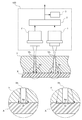
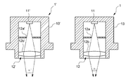
- the whole schematic diagram which shows the radiation thermometer in the 1st Embodiment of this invention The schematic diagram which shows the internal structure of the infrared ray detection part in the same embodiment.
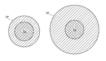
- the visual field view which shows the measurement target area and other area (non-object) in the measurement visual field in the same embodiment.
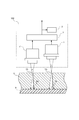
- the whole schematic diagram which shows the radiation thermometer in the modification of the same embodiment The whole schematic diagram which shows the radiation thermometer in still another modification of this embodiment.
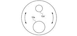
- the schematic diagram which shows the diaphragm in still another modification of this embodiment.
- the radiation thermometer 100 measures the temperature of the measurement target region Xa in the object X as shown in FIG. 1 in a non-contact manner, and detects infrared rays emitted from the object X.
- the object X has a flat plate shape, and a heat transfer block Y for controlling the temperature of the object X is attached to one surface of the object X. ..
- the radiation thermometer 100 is arranged on one surface side of the object X, and as it is, the heat transfer block Y interferes with the temperature of the object X, so that the temperature of the object X cannot be measured.
- Pore Yh having the same diameter is formed in two places, and the temperature of the object X can be measured through the pore Yh. Therefore, in the object X, the region exposed through the pores Yh is the measurement target region Xa.
- pores Yh are provided at two places of the heat transfer block 7, and the measurement target area Xa is apparently provided.
- these two measurement target regions Xa have substantially the same area, the same shape, and the same temperature, and can be regarded as the same measurement target region Xa.
- the heat transfer blocks 7 around each pore Yh have the same temperature and shape, it can be considered that the ambient conditions of these two measurement target regions Xa are also the same.
- two measurement target areas Xa that are substantially the same in all including the surrounding conditions are provided so that it can be regarded that one and the same measurement target area Xa is being measured.
- the pair of infrared detection units 1, 1' are a sensor element 11, 11'such as a thermopile that detects infrared rays, and an optical system 12 arranged in front of the sensor elements 11, 11', respectively. , 12', and housings 13, 13' for accommodating these sensor elements 11, 11'and optical systems 12, 12'.
- a sensor element 11, 11' such as a thermopile that detects infrared rays
- an optical system 12 arranged in front of the sensor elements 11, 11', respectively.
- 12', and housings 13, 13' for accommodating these sensor elements 11, 11'and optical systems 12, 12'.
- each of these infrared detection units 1, 1' are arranged side by side so as to face the pore Yh, and infrared rays from the measurement target region Xa at the bottom of one pore Yh are detected by one infrared detection unit.
- 1 first infrared detection unit 1
- the other infrared detection unit 1' receives infrared rays from the measurement target region Xa at the bottom of the other pore Yh. It is configured.
- the distances between the infrared detection units 1 and 1'and the corresponding measurement target areas Xa are set to be equal.
- the sensor elements 11 and 11' are of a thermal type that detects a temperature change when absorbing infrared rays as a change in electromotive force, and here, a thermopile in which a large number of thermocouples are arranged in series to form a thin film is used.
- a thermopile in which a large number of thermocouples are arranged in series to form a thin film is used.
- the sensor element another thermal type such as a poromometer or a pyroelectric type may be used, or a quantum type sensor element may be used instead of the thermal type.
- the optical systems 12 and 12' are composed of lenses 12b and 12b' and diaphragms 12a and 12a' provided in front of the sensor elements 11 and 11', and the sensor elements 11 and 11'are externally provided. It defines the solid angles (viewing angles) ⁇ and ⁇ 'of the infrared rays incident on the lens, and thus defines the measurement fields of view Vf and Vf'.
- the measurement visual fields Vf and Vf'of each infrared detection unit 1, 1' are set to include all the corresponding measurement target areas Xa and also include the peripheral area of the measurement target area Xa.
- the first infrared ray detection unit 1 and the second infrared ray detection unit 1' are different only in their viewing angles ⁇ and ⁇ 'and are based on the measurement target region Xa.
- the sizes of the measurement visual fields Vf and Vf' are different from each other, in other words, the ratio of the area occupied by the measurement target region Xa in each measurement visual field Vf and Vf' is different.
- only the lens curvatures of the optical systems 12 and 12'are different, and the other configurations are the same.
- FIG. 3 illustrates the size of each measurement field of view Vf, Vf'when the measurement target area Xa is used as a reference.
- the regions other than the measurement target region Xa in each measurement field of view Vf, Vf' are the inner wall of the pore Yh, and the infrared rays from the inner wall of the pore Yh are each. It is incident on the infrared detectors 1, 1'.
- the temperature calculation unit 2 is composed of electric circuits (not shown) such as a buffer, an amplifier, an AD converter, a CPU, and a memory, and the CPU cooperates with peripheral devices according to a program stored in the memory. , The function of calculating the temperature of the temperature measurement target region Xa based on the value of the detection signal output from each of the sensor elements 11 and 11'is exhibited. The temperature calculated by the temperature calculation unit 2 is output as a temperature signal.
- the temperature display unit 3 is provided with a display or the like, receives the temperature signal, and displays the temperature on the display.
- the temperature calculation unit 2 and the temperature display unit 4 do not need to be in the vicinity of the infrared detection units 1 and 1', and their arrangement positions do not matter as long as they are connected by wire or wirelessly.
- a temperature control device (not shown) that receives the temperature signal and controls the temperature of the object may be provided, and the temperature measurement control system may be configured by the radiation thermometer 100 and the temperature control device. ..
- the value of the detection signal output from each of the sensor elements 11 and 11' (hereinafter, also referred to as the amount of detected infrared rays) is the temperature of the measurement target area Xa and the area occupied by the measurement target area Xa in the measurement fields Vf and Vf'. It is the sum of the value obtained by multiplying the ratio and the value obtained by multiplying the temperature of the surroundings (heat transfer block Y) by the ratio of the area occupied by the surroundings in the measurement fields Vf and Vf'.
- the measurement field of view is one of the field of view characteristics (the field of view characteristic is composed of various indexes indicating what kind of field of view the radiation thermometer has), and radiation is emitted at a certain measurement distance. It is the size of the target size set by the thermometer as the measurement target. Generally, the measurement field of view has a diameter corresponding to 90% of the total incident energy.
- E ( ⁇ , T) be the spectral radiant energy for the wavelength ⁇ of the blackbody at temperature T.
- the temperature of the measurement target area Xa is T 1
- the ambient temperature is T 2
- the measurement target area Xa in the measurement field Vf of the infrared detector 1 occupies.
- the ratio (area ratio) is R 2 , the spectral radiant energy incident on the sensor element 11 of the first infrared detector 1 is W 1 , and the spectral radiant energy incident on the sensor element 11'of the second infrared detector 1'is W 1.
- the temperature calculation unit 2 stores the equations (3) and (4) and the known values of R 1 and R 2 in the memory, and the detection signal obtained by each infrared detection unit 1, 1'.
- the temperature T 1 of the measurement target region Xa is calculated by applying the values W 1 and W 2 and the values of R 1 and R 2 to the above equations (3) and (4).
- the measurement target region Xa of the measurement target region Xa is irrespective of the temperature of the region other than the measurement target region Xa. Since the temperature can be measured, accurate temperature measurement is possible without being affected by temporal temperature changes in other regions or local temperature gradients.
- the viewing angle of each infrared detection unit 1,1' may be set, and the separation distance between the temperature measurement target region Xa and each infrared detection unit 1, 1'may be different. ..
- both the viewing angle and the separation distance may be different from each other.
- the same measurement target region Xa is provided in the above embodiment including the ambient conditions.
- a beam splitter 31 may be provided to divide the infrared rays into two, and each of them may be introduced into each infrared detection unit 1, 1'.
- the viewing angles of the infrared detection units 1, 1' are the same, but the separation distance (optical path length) between the temperature measurement target region Xa and each infrared detection unit 1, 1'is different as described above.
- Reference numeral 32 is a mirror.
- the present invention can be realized even with a single infrared detector.
- a zoom mechanism capable of adjusting the lens position of the optical system is provided, and measurement is performed twice with a predetermined time interval.
- the scaling factor by the zoom mechanism (the area occupied by the temperature measurement target area in the measurement field in each measurement). Percentage of) may be different.
- the first measurement field of view including the measurement target area is set by adjusting the zoom mechanism, and the amount of infrared rays incident from the first measurement field of view is detected.
- the zoom mechanism zooms in on the second measurement field of view in which the measurement target area is included and the size of the measurement field of view when the measurement target area is used as a reference is different from that of the first measurement field of view. Is adjusted and set, and the amount of infrared rays incident from the second measurement field of view may be detected.
- the temperature of the measurement target region may be calculated by the same method as in the above embodiment.
- This method can be realized not only by providing an optical system but also by providing, for example, a distance adjusting mechanism capable of adjusting the distance between the infrared detection unit and the temperature measurement target area and changing the distance.
- the radiation thermometer 100 as shown in FIG. 6 may be used.
- two sensor elements 11 and 11' (here, these correspond to the infrared detection unit referred to in the claim) are provided in a single housing, and the lens 12b is shared from the lens 12b. It is configured so that either the mirror 12c or the light transmitting plate 12d can be selectively arranged on the light path of the incident infrared rays. More specifically, in this example, the mirror 12c and the translucent plate 12d are alternately formed on one disk as shown in FIG. 7, and by rotating this disk, any one of them is formed. Can be placed on the optical path.
- one sensor element 11 becomes effective, that is, infrared rays from the measurement target region are incident on the sensor element 11, and when the mirror is selected, the other sensor is used.
- the element 11' is effective, that is, the sensor element 11'is incident with infrared light from the measurement target region.
- the optical path lengths from the lens 12b to the sensor elements 11 and 11' are different from each other, and the size of the measurement field of view by the sensor element 11 and the measurement field of view by the sensor element 11'(more accurately, the temperature in the measurement field of view).
- the ratio of the area occupied by the measurement target area) is different. It should be noted that the measurement procedure in this example needs to be performed in two steps of the mirror 12c and the translucent plate 12d, as in the case of the zoom mechanism.
- the measurement field of view can be changed by changing the diameter of the diaphragm in the optical system.
- the measurement field of view can be changed by changing the diameter of each diaphragm without changing the lens power or the optical path length.
- two diaphragms having different diameters may be provided so that they can be moved so that either one can be used.
- two diaphragms having different diameters are provided on the disk so that the disk can be rotated and one of them can be selectively used.
- the aperture may be selected by sliding movement, or the aperture diameter may be changed by a variable aperture mechanism.
- the temperature calculation routine by the temperature calculation unit is not limited to the above embodiment, for example, the temperature of the measurement target region is obtained by using simultaneous equations, a temperature map is created in advance by an experiment, and measurement is performed based on the temperature map. The temperature of the target area may be obtained.
- the object X may be a linear object such as a wire.
- a pair of infrared detection units 1, 1' are provided as in the above embodiment to provide two places of the object X.
- Each is regarded as the same temperature and measured.
- the measurement fields of view Vf and Vf'of the infrared detection units 1 and 1' are different from each other, and the ratio of the object X (measurement target area) in each measurement field of view Vf and Vf' is set to be different. There is.
- the radiation thermometer 100 measures the temperature of the measurement target region Xa in the object X in a non-contact manner, and detects infrared rays emitted from the object X.
- the object X has a low emissivity (high transmittance) in an infrared wavelength band (hereinafter, detected infrared wavelength band) that can be detected by the infrared detection units 1, 1', and has a background.
- Infrared rays that pass through the object X from the object Z and enter the infrared sensor can also exist.
- the pair of infrared detection units 1, 1' are a sensor element 11, 11'such as a thermopile that detects infrared rays, and a pre-stage of the sensor elements 11, 11', respectively, as shown in FIG.
- the optical system 12, 12' arranged in the above, and the housings 13, 13' accommodating the sensor elements 11, 11'and the optical system 12, 12'are provided.
- the sensor elements 11, 11', the optical systems 12, 12', and the housings 13, 13' are the same, and the viewing angles are also the same. Further, the distance between the temperature measurement target region Xa and each infrared detection unit 1, 1'is also set to be equal.
- optical filters 14, 14'in which the transmitted infrared wavelength bands are different from each other are provided in the front stage or the rear stage of the optical system.
- the detection infrared wavelength bands (first detection infrared wavelength band and second detection infrared wavelength band), which are the wavelength bands that can be detected by each infrared detection unit 1, 1', are configured to be different from each other. ..
- “different from each other” includes those in which the wavelength bands partially overlap. The point is that it does not have to be exactly the same.
- each infrared detection unit 1, 1' is the same (in FIG. 10, they are different points in the object X, but can be regarded as the same).
- the temperature calculation unit 2 determines the temperature of the measurement target region Xa based on the values of the detection signals (first detected infrared amount and second detected infrared amount) output from the infrared detection units 1 and 1', respectively. It is to be calculated.
- the calculation principle is as follows.
- the total amount of infrared rays in the predetermined wavelength band incident on each infrared detection unit 1, 1' is the sum of the infrared rays A1 from the measurement target area Xa, the infrared rays A2 from behind the infrared rays A2, and the infrared rays A3 reflected by the measurement target area Xa. is there.
- the spectral radiant energy from the measurement target area Xa of the infrared detection unit 1 is E 1 (Tx)
- the spectral radiant energy from the background of the measurement target area Xa of the infrared detection unit 1 is E 1 (T background )
- the infrared detection unit 1' If the spectral radiant energy from the measurement target region Xa of is E 2 (Tx) and the spectral radiant energy from the background of the measurement target region Xa of the second infrared detection unit 1'is E 2 (T background ), the first infrared detection is detected.
- the second embodiment having such a configuration, in the background of the measurement target region Xa, there is a non-object that emits infrared rays transmitted through the measurement visual field region, and the temperature of the non-object changes. However, the influence can be surely eliminated.
- Japanese Patent Application Laid-Open No. 10-38696 describes a configuration in which an infrared sensor in two wavelength bands is used to eliminate the temperature effect of a non-object.
- this document does not exclude the influence of infrared rays transmitted through the measurement target area in the first place, and calculates the temperature influence of non-objects based only on the ratio of the outputs of each infrared sensor. Therefore, if the temperature of the non-object fluctuates, an error will occur in the temperature measurement of the measurement target area.
- the dichotomy method as in the first embodiment may be used, or a correlation equation may be created in advance by an experiment and the temperature of the measurement target region may be obtained based on the correlation equation. ..
- the present invention can be realized even with a single infrared detector 1.
- a moving mechanism for selectively moving any of the optical filters 14 and 14'in which the transmitted infrared wavelength bands are different from each other on the optical path is provided, and in the first measurement, the first measurement is performed.
- the optical filter 14 may be used, and the second optical filter 14'may be used in the second measurement at intervals of a predetermined time. After acquiring the amount of infrared rays in each of the two measurements in this way, the temperature of the measurement target region may be calculated by the same method as in the above embodiment.
- a rotating disk is used as the moving mechanism, but a slide mechanism or the like may be used.
- the number of optical filters is not limited to two, and may be three or more. Similarly, three or more infrared detection units having different detection infrared wavelength bands may be used.
- the radiation thermometer 100 measures the temperature of the measurement target region Xa in the object X in a non-contact manner, and detects infrared rays emitted from the object X.
- the object X has a transmittance of 0.
- the measurement field of view is the size of the target size set as the measurement target by the radiation thermometer defined based on the measurement optical axis ⁇ .
- the sensor elements 11, 11', the optical systems 12, 12', and the housings 13, 13' are the same, and the viewing angles are also the same.
- the optical path lengths of the temperature measurement target region Xa and the infrared detection units 1, 1'on the measurement optical axis ⁇ are also set to be equal.
- the intersection of the measurement optical axis ⁇ of each infrared detection unit 1, 1'on the surface of the measurement target region Xa is also matched.
- the angles of the measurement optical axes ⁇ of the infrared detection units 1, 1'with respect to the object surface Xs are set to be different from each other.
- the temperature calculation unit 2 sets the values of the detection signals (first detected infrared amount and second detected infrared amount) output from the infrared detection units 1 and 1', and the reflectance or emissivity at each angle. Based on this, the temperature of the measurement target region Xa is calculated.
- the calculation principle is as follows. When the angle ⁇ of the measurement optical axis ⁇ with respect to the object surface Xs changes, the reflectance R and the emissivity ⁇ also change, so that the spectral radiant energies W incident on the infrared detection units 1, 1'are different from each other.
- the data from different angles that is, the first detected infrared amount and the second detected infrared amount, and the known reflectances R ( ⁇ 1 ), R ( ⁇ 2 ) or emissivity at each of the angles ⁇ 1 and ⁇ 2.
- the object temperature is calculated from one or both of ⁇ ( ⁇ 1 ) and ⁇ ( ⁇ 2) by a simultaneous equation or a dichotomy.
- the spectral radiant energy (second detected infrared amount) W 2 detected by the second infrared detection unit 1' is
- definitive is unknown, E (T X ), since it is two of E (T R), by using (8) and (9)
- T X E -1 ((( 1- ⁇ ( ⁇ 2)) ⁇ W 1 - (1- ⁇ ( ⁇ 1)) ⁇ W 2) / ( ⁇ 1 + ⁇ 2)) ⁇ (10)
- T X E -1 ((( 1- ⁇ ( ⁇ 2)) ⁇ W 1 - (1- ⁇ ( ⁇ 1)) ⁇ W 2) / ( ⁇ 1 + ⁇ 2)) ⁇ (10)
- T X E -1 ((( 1- ⁇ ( ⁇ 2)) ⁇ W 1 - (1- ⁇ ( ⁇ 1)) ⁇ W 2) / ( ⁇ 1 + ⁇ 2)) ⁇ (10)
- T X E -1 ((( 1- ⁇ ( ⁇ 2)) ⁇ W 1 - (1- ⁇ ( ⁇ 1)) ⁇ W 2) / ( ⁇ 1
- the equation (10) As is apparent from the absence of T R, regardless of the temperature of the region other than the measurement target region Xa, the measurement target region Xa Since it is possible to measure the temperature of the above, it is possible to measure the temperature with high accuracy without being affected by the temporal temperature change in other regions and the local temperature gradient.
- the dichotomy method as in the first embodiment may be used, or a correlation equation may be created in advance by an experiment and the temperature of the measurement target region may be obtained based on the correlation equation. ..
- the present invention can be realized even with a single infrared detector 1.
- the infrared detection unit 1 is mechanically moved to provide an angle adjustment mechanism for adjusting the angle of the measurement optical axis ⁇ with respect to the object surface Xs, and the first measurement is performed at an arbitrary angle.
- the second measurement may be performed at a different angle from.
- the temperature of the measurement target region may be calculated by the same method as in the above embodiment.
- the intersection of the measurement optical axis ⁇ and the surface of the object Xs does not have to be exactly the same.
- the intersection of the measurement optical axis ⁇ and the object Xs may be set so that the measurement target region Xa is included in the measurement field of view when each angle ⁇ is set.
- each infrared detection unit may be different for each detection unit.
- the infrared optical path length detected by each infrared detection unit does not have to be the same. That is, it is sufficient that each infrared detection unit can detect infrared rays in a state where the reflectance of infrared rays reflected in the measurement target region is different.
- each infrared detection unit may be able to detect different wavelengths. In such a case, the temperature can be accurately calculated by the temperature calculation method described in the third embodiment even if the angle formed by the measurement optical axis of each infrared detection unit and the measurement target region is the same.
- infrared detection units having different angles may be provided. It is also possible to combine some or all of the first to third embodiments.
- thermometer capable of accurately measuring the temperature of a temperature measurement target region in a non-contact manner regardless of how the temperature of a region other than the measurement target region changes.
Landscapes
- Physics & Mathematics (AREA)
- General Physics & Mathematics (AREA)
- Spectroscopy & Molecular Physics (AREA)
- Radiation Pyrometers (AREA)
Priority Applications (5)
| Application Number | Priority Date | Filing Date | Title |
|---|---|---|---|
| JP2021553573A JP7785539B2 (ja) | 2019-10-25 | 2020-10-23 | 放射温度計、温度測定方法及び温度測定プログラム |
| EP26151326.1A EP4707759A1 (en) | 2019-10-25 | 2020-10-23 | Radiation thermometer, temperature measurement method, and temperature measurement program |
| US17/770,736 US12523532B2 (en) | 2019-10-25 | 2020-10-23 | Radiation thermometer, temperature measurement method, and temperature measurement program |
| EP20878512.1A EP4040122B1 (en) | 2019-10-25 | 2020-10-23 | Radiation thermometer, temperature measurement method, and temperature measurement program |
| JP2025226291A JP2026026307A (ja) | 2019-10-25 | 2025-12-03 | 放射温度計、温度測定方法及び温度測定プログラム |
Applications Claiming Priority (4)
| Application Number | Priority Date | Filing Date | Title |
|---|---|---|---|
| JP2019-194134 | 2019-10-25 | ||
| JP2019194134 | 2019-10-25 | ||
| JP2020-071243 | 2020-04-10 | ||
| JP2020071243 | 2020-04-10 |
Publications (1)
| Publication Number | Publication Date |
|---|---|
| WO2021080002A1 true WO2021080002A1 (ja) | 2021-04-29 |
Family
ID=75620149
Family Applications (1)
| Application Number | Title | Priority Date | Filing Date |
|---|---|---|---|
| PCT/JP2020/039962 Ceased WO2021080002A1 (ja) | 2019-10-25 | 2020-10-23 | 放射温度計、温度測定方法及び温度測定プログラム |
Country Status (4)
| Country | Link |
|---|---|
| US (1) | US12523532B2 (https=) |
| EP (2) | EP4040122B1 (https=) |
| JP (2) | JP7785539B2 (https=) |
| WO (1) | WO2021080002A1 (https=) |
Cited By (1)
| Publication number | Priority date | Publication date | Assignee | Title |
|---|---|---|---|---|
| WO2024241674A1 (ja) | 2023-05-25 | 2024-11-28 | 株式会社堀場製作所 | 放射温度測定装置、放射温度測定方法及び放射温度測定装置用プログラム |
Families Citing this family (1)
| Publication number | Priority date | Publication date | Assignee | Title |
|---|---|---|---|---|
| CN115711730A (zh) * | 2022-11-29 | 2023-02-24 | 北京航天长征飞行器研究所 | 一种运动、能量、尺度连续可控的红外目标模拟系统 |
Citations (8)
| Publication number | Priority date | Publication date | Assignee | Title |
|---|---|---|---|---|
| JPS62106328A (ja) | 1985-11-01 | 1987-05-16 | Tokyo Electric Power Co Inc:The | 放射温度計 |
| JPS6375629A (ja) * | 1986-09-19 | 1988-04-06 | Minolta Camera Co Ltd | 放射温度計 |
| JPS63285429A (ja) * | 1987-05-18 | 1988-11-22 | Teijin Ltd | 走行糸温度計 |
| JPH08320258A (ja) * | 1995-05-25 | 1996-12-03 | Matsushita Electric Ind Co Ltd | 熱画像情報と位置情報を利用した物体検出方法およびその装置 |
| JPH1038696A (ja) | 1996-07-18 | 1998-02-13 | Sony Corp | 赤外線検出装置 |
| JP2002188962A (ja) * | 2000-12-19 | 2002-07-05 | Tokyo Electron Ltd | 放射温度測定装置と放射温度測定方法及び半導体製造装置 |
| JP2013200137A (ja) * | 2012-03-23 | 2013-10-03 | Omron Corp | 赤外線温度測定装置、赤外線温度測定方法、および、赤外線温度測定装置の制御プログラム |
| JP2014169924A (ja) * | 2013-03-04 | 2014-09-18 | Mikuni Corp | 温度測定装置 |
Family Cites Families (11)
| Publication number | Priority date | Publication date | Assignee | Title |
|---|---|---|---|---|
| JPS61231422A (ja) * | 1985-04-06 | 1986-10-15 | Horiba Ltd | 放射温度計 |
| JPH0756471B2 (ja) * | 1988-09-27 | 1995-06-14 | 登 中谷 | レーザ多焦点法による粒子の速度、径、屈折率の同時測定方法 |
| US5249142A (en) * | 1989-03-31 | 1993-09-28 | Tokyo Electron Kyushu Limited | Indirect temperature-measurement of films formed on semiconductor wafers |
| JP2832456B2 (ja) | 1989-06-02 | 1998-12-09 | 株式会社加藤製作所 | 特殊車両のアウトリガ |
| JP2001249050A (ja) | 2000-03-07 | 2001-09-14 | Toshiba Corp | 温度測定装置、成膜装置、エッチング装置および温度測定方法、エッチング方法 |
| JP2005207997A (ja) | 2004-01-26 | 2005-08-04 | Dainippon Screen Mfg Co Ltd | 基板処理装置 |
| JP2007183207A (ja) | 2006-01-10 | 2007-07-19 | Yamatake Corp | 放射温度センサおよび放射温度計測装置 |
| US8254767B2 (en) | 2008-08-29 | 2012-08-28 | Applied Materials, Inc. | Method and apparatus for extended temperature pyrometry |
| KR101500965B1 (ko) * | 2011-07-06 | 2015-03-17 | 가부시키가이샤 무라타 세이사쿠쇼 | 적층형 전자부품의 적층방향 판정방법, 적층형 전자부품의 적층방향 판정장치, 연속 적층형 전자부품의 제조방법, 및 연속 적층형 전자부품의 제조장치 |
| KR20170099157A (ko) * | 2016-02-23 | 2017-08-31 | 삼성전자주식회사 | 온도 정보를 제공하는 방법 및 이를 지원하는 전자 장치 |
| JPWO2022215417A1 (https=) * | 2021-04-09 | 2022-10-13 |
-
2020
- 2020-10-23 EP EP20878512.1A patent/EP4040122B1/en active Active
- 2020-10-23 US US17/770,736 patent/US12523532B2/en active Active
- 2020-10-23 WO PCT/JP2020/039962 patent/WO2021080002A1/ja not_active Ceased
- 2020-10-23 JP JP2021553573A patent/JP7785539B2/ja active Active
- 2020-10-23 EP EP26151326.1A patent/EP4707759A1/en active Pending
-
2025
- 2025-12-03 JP JP2025226291A patent/JP2026026307A/ja active Pending
Patent Citations (8)
| Publication number | Priority date | Publication date | Assignee | Title |
|---|---|---|---|---|
| JPS62106328A (ja) | 1985-11-01 | 1987-05-16 | Tokyo Electric Power Co Inc:The | 放射温度計 |
| JPS6375629A (ja) * | 1986-09-19 | 1988-04-06 | Minolta Camera Co Ltd | 放射温度計 |
| JPS63285429A (ja) * | 1987-05-18 | 1988-11-22 | Teijin Ltd | 走行糸温度計 |
| JPH08320258A (ja) * | 1995-05-25 | 1996-12-03 | Matsushita Electric Ind Co Ltd | 熱画像情報と位置情報を利用した物体検出方法およびその装置 |
| JPH1038696A (ja) | 1996-07-18 | 1998-02-13 | Sony Corp | 赤外線検出装置 |
| JP2002188962A (ja) * | 2000-12-19 | 2002-07-05 | Tokyo Electron Ltd | 放射温度測定装置と放射温度測定方法及び半導体製造装置 |
| JP2013200137A (ja) * | 2012-03-23 | 2013-10-03 | Omron Corp | 赤外線温度測定装置、赤外線温度測定方法、および、赤外線温度測定装置の制御プログラム |
| JP2014169924A (ja) * | 2013-03-04 | 2014-09-18 | Mikuni Corp | 温度測定装置 |
Non-Patent Citations (1)
| Title |
|---|
| See also references of EP4040122A4 |
Cited By (2)
| Publication number | Priority date | Publication date | Assignee | Title |
|---|---|---|---|---|
| WO2024241674A1 (ja) | 2023-05-25 | 2024-11-28 | 株式会社堀場製作所 | 放射温度測定装置、放射温度測定方法及び放射温度測定装置用プログラム |
| EP4692742A1 (en) | 2023-05-25 | 2026-02-11 | HORIBA, Ltd. | Radiation temperature measurement device, radiation temperature measurement method, and program for radiation temperature measurement device |
Also Published As
| Publication number | Publication date |
|---|---|
| JP7785539B2 (ja) | 2025-12-15 |
| US20220364930A1 (en) | 2022-11-17 |
| JP2026026307A (ja) | 2026-02-16 |
| EP4040122B1 (en) | 2026-02-18 |
| EP4040122A1 (en) | 2022-08-10 |
| EP4707759A1 (en) | 2026-03-11 |
| US12523532B2 (en) | 2026-01-13 |
| JPWO2021080002A1 (https=) | 2021-04-29 |
| EP4040122A4 (en) | 2023-11-22 |
Similar Documents
| Publication | Publication Date | Title |
|---|---|---|
| JP2026026307A (ja) | 放射温度計、温度測定方法及び温度測定プログラム | |
| TW440687B (en) | Radiation thermometer and radiation sensor with multiple sensor elements and method for determining a temperature | |
| US8830473B2 (en) | Device for referenced measurements of reflected light and a method for calibrating such a device | |
| CN106768855B (zh) | 一种大口径辐射计的光谱响应度测量装置及方法 | |
| US8240912B2 (en) | Multi-zone non-contact spot thermometer | |
| KR20230025483A (ko) | 광학 장치, 색채 휘도계 및 색채계 | |
| WO2015002964A1 (en) | Infrared contrasting color temperature measurement system, | |
| US4605314A (en) | Spectral discrimination pyrometer | |
| EP2920563B1 (en) | Medical radiation thermometer having an improved optics system | |
| KR101164640B1 (ko) | 동일시계 및 영상을 갖는 적외선 열화상 카메라 장치 | |
| CN207515908U (zh) | 一种多光路自定标偏振探测装置及系统 | |
| RU2622239C1 (ru) | Устройство для бесконтактного измерения температуры объекта | |
| US7518113B2 (en) | Pressure sensor | |
| EP1729102B1 (en) | Detector with miniature optics for constant energy collection from different distances | |
| JP3325700B2 (ja) | 光ファイバ放射温度計 | |
| EP4328555A1 (en) | Pyrometer with high spatial resolution | |
| JP7350672B2 (ja) | ミラー間の多重反射を利用した放射測温装置 | |
| JP2002333370A (ja) | 赤外線検出器およびこれを用いた放射体温計 | |
| JP2000139849A (ja) | 赤外線検出器およびこれを用いた放射体温計 | |
| IL110549A (en) | Multipoint temperature monitoring apparatus for semiconductor wafers during processing | |
| JP2026506867A (ja) | 2つのledとオープンポート較正の組み合わせ | |
| CN111562019A (zh) | 一种多光谱辐射测温方法及系统 | |
| JPH0342531A (ja) | 赤外線計測装置 | |
| JP2002333369A (ja) | 赤外線検出器およびこれを用いた放射体温計 | |
| JPS62261933A (ja) | 放射温度計及びその使用方法 |
Legal Events
| Date | Code | Title | Description |
|---|---|---|---|
| 121 | Ep: the epo has been informed by wipo that ep was designated in this application |
Ref document number: 20878512 Country of ref document: EP Kind code of ref document: A1 |
|
| ENP | Entry into the national phase |
Ref document number: 2021553573 Country of ref document: JP Kind code of ref document: A |
|
| NENP | Non-entry into the national phase |
Ref country code: DE |
|
| ENP | Entry into the national phase |
Ref document number: 2020878512 Country of ref document: EP Effective date: 20220502 |
|
| WWG | Wipo information: grant in national office |
Ref document number: 17770736 Country of ref document: US |
|
| WWG | Wipo information: grant in national office |
Ref document number: 2020878512 Country of ref document: EP |