WO2021075387A1 - 水力発電システム - Google Patents
水力発電システム Download PDFInfo
- Publication number
- WO2021075387A1 WO2021075387A1 PCT/JP2020/038364 JP2020038364W WO2021075387A1 WO 2021075387 A1 WO2021075387 A1 WO 2021075387A1 JP 2020038364 W JP2020038364 W JP 2020038364W WO 2021075387 A1 WO2021075387 A1 WO 2021075387A1
- Authority
- WO
- WIPO (PCT)
- Prior art keywords
- flow path
- fluid
- flow rate
- pressure
- control
- Prior art date
Links
- 238000010248 power generation Methods 0.000 title claims description 85
- 239000012530 fluid Substances 0.000 claims abstract description 389
- XLYOFNOQVPJJNP-UHFFFAOYSA-N water Substances O XLYOFNOQVPJJNP-UHFFFAOYSA-N 0.000 claims description 186
- 239000007788 liquid Substances 0.000 claims description 99
- 238000013459 approach Methods 0.000 claims description 60
- 230000007246 mechanism Effects 0.000 claims description 26
- 238000009795 derivation Methods 0.000 description 45
- 238000000034 method Methods 0.000 description 37
- 230000008569 process Effects 0.000 description 32
- 230000004048 modification Effects 0.000 description 25
- 238000012986 modification Methods 0.000 description 25
- 230000007423 decrease Effects 0.000 description 20
- 238000004364 calculation method Methods 0.000 description 19
- 238000001514 detection method Methods 0.000 description 17
- 230000001276 controlling effect Effects 0.000 description 15
- 238000010586 diagram Methods 0.000 description 9
- 238000009434 installation Methods 0.000 description 9
- 230000000694 effects Effects 0.000 description 7
- 230000008859 change Effects 0.000 description 6
- 230000006870 function Effects 0.000 description 2
- 229910001141 Ductile iron Inorganic materials 0.000 description 1
- 230000001133 acceleration Effects 0.000 description 1
- 239000003990 capacitor Substances 0.000 description 1
- 230000003247 decreasing effect Effects 0.000 description 1
- 230000005611 electricity Effects 0.000 description 1
- 238000009499 grossing Methods 0.000 description 1
- 239000002184 metal Substances 0.000 description 1
- 229910052751 metal Inorganic materials 0.000 description 1
- 230000001105 regulatory effect Effects 0.000 description 1
- 230000004044 response Effects 0.000 description 1
- 230000004043 responsiveness Effects 0.000 description 1
- 229920006395 saturated elastomer Polymers 0.000 description 1
Images


Classifications
-
- F—MECHANICAL ENGINEERING; LIGHTING; HEATING; WEAPONS; BLASTING
- F03—MACHINES OR ENGINES FOR LIQUIDS; WIND, SPRING, OR WEIGHT MOTORS; PRODUCING MECHANICAL POWER OR A REACTIVE PROPULSIVE THRUST, NOT OTHERWISE PROVIDED FOR
- F03B—MACHINES OR ENGINES FOR LIQUIDS
- F03B15/00—Controlling
- F03B15/02—Controlling by varying liquid flow
- F03B15/04—Controlling by varying liquid flow of turbines
- F03B15/06—Regulating, i.e. acting automatically
- F03B15/08—Regulating, i.e. acting automatically by speed, e.g. by measuring electric frequency or liquid flow
-
- F—MECHANICAL ENGINEERING; LIGHTING; HEATING; WEAPONS; BLASTING
- F03—MACHINES OR ENGINES FOR LIQUIDS; WIND, SPRING, OR WEIGHT MOTORS; PRODUCING MECHANICAL POWER OR A REACTIVE PROPULSIVE THRUST, NOT OTHERWISE PROVIDED FOR
- F03B—MACHINES OR ENGINES FOR LIQUIDS
- F03B15/00—Controlling
- F03B15/02—Controlling by varying liquid flow
- F03B15/04—Controlling by varying liquid flow of turbines
- F03B15/06—Regulating, i.e. acting automatically
- F03B15/16—Regulating, i.e. acting automatically by power output
-
- H—ELECTRICITY
- H02—GENERATION; CONVERSION OR DISTRIBUTION OF ELECTRIC POWER
- H02K—DYNAMO-ELECTRIC MACHINES
- H02K7/00—Arrangements for handling mechanical energy structurally associated with dynamo-electric machines, e.g. structural association with mechanical driving motors or auxiliary dynamo-electric machines
- H02K7/18—Structural association of electric generators with mechanical driving motors, e.g. with turbines
- H02K7/1807—Rotary generators
- H02K7/1823—Rotary generators structurally associated with turbines or similar engines
-
- F—MECHANICAL ENGINEERING; LIGHTING; HEATING; WEAPONS; BLASTING
- F05—INDEXING SCHEMES RELATING TO ENGINES OR PUMPS IN VARIOUS SUBCLASSES OF CLASSES F01-F04
- F05B—INDEXING SCHEME RELATING TO WIND, SPRING, WEIGHT, INERTIA OR LIKE MOTORS, TO MACHINES OR ENGINES FOR LIQUIDS COVERED BY SUBCLASSES F03B, F03D AND F03G
- F05B2220/00—Application
- F05B2220/20—Application within closed fluid conduits, e.g. pipes
-
- F—MECHANICAL ENGINEERING; LIGHTING; HEATING; WEAPONS; BLASTING
- F05—INDEXING SCHEMES RELATING TO ENGINES OR PUMPS IN VARIOUS SUBCLASSES OF CLASSES F01-F04
- F05B—INDEXING SCHEME RELATING TO WIND, SPRING, WEIGHT, INERTIA OR LIKE MOTORS, TO MACHINES OR ENGINES FOR LIQUIDS COVERED BY SUBCLASSES F03B, F03D AND F03G
- F05B2220/00—Application
- F05B2220/70—Application in combination with
- F05B2220/706—Application in combination with an electrical generator
-
- F—MECHANICAL ENGINEERING; LIGHTING; HEATING; WEAPONS; BLASTING
- F05—INDEXING SCHEMES RELATING TO ENGINES OR PUMPS IN VARIOUS SUBCLASSES OF CLASSES F01-F04
- F05B—INDEXING SCHEME RELATING TO WIND, SPRING, WEIGHT, INERTIA OR LIKE MOTORS, TO MACHINES OR ENGINES FOR LIQUIDS COVERED BY SUBCLASSES F03B, F03D AND F03G
- F05B2270/00—Control
- F05B2270/30—Control parameters, e.g. input parameters
- F05B2270/301—Pressure
-
- F—MECHANICAL ENGINEERING; LIGHTING; HEATING; WEAPONS; BLASTING
- F05—INDEXING SCHEMES RELATING TO ENGINES OR PUMPS IN VARIOUS SUBCLASSES OF CLASSES F01-F04
- F05B—INDEXING SCHEME RELATING TO WIND, SPRING, WEIGHT, INERTIA OR LIKE MOTORS, TO MACHINES OR ENGINES FOR LIQUIDS COVERED BY SUBCLASSES F03B, F03D AND F03G
- F05B2270/00—Control
- F05B2270/30—Control parameters, e.g. input parameters
- F05B2270/34—Water level
-
- F—MECHANICAL ENGINEERING; LIGHTING; HEATING; WEAPONS; BLASTING
- F05—INDEXING SCHEMES RELATING TO ENGINES OR PUMPS IN VARIOUS SUBCLASSES OF CLASSES F01-F04
- F05B—INDEXING SCHEME RELATING TO WIND, SPRING, WEIGHT, INERTIA OR LIKE MOTORS, TO MACHINES OR ENGINES FOR LIQUIDS COVERED BY SUBCLASSES F03B, F03D AND F03G
- F05B2270/00—Control
- F05B2270/30—Control parameters, e.g. input parameters
- F05B2270/341—Liquid flow velocity or direction
Definitions
- This disclosure relates to a hydroelectric power generation system.
- Patent Document 1 discloses a hydroelectric power generation system.
- This hydroelectric power generation system includes a water turbine arranged in a flow path through which a fluid flows, a generator driven by the water turbine, a head adjusting means for adjusting the effective head of the water turbine, and a control unit.
- the control unit controls the generator so that the flow rate of the turbine approaches the target flow rate, and the head adjustment control that adjusts the effective head of the turbine by the head adjusting means so that the effective head of the turbine is within the first range. And in cooperation.
- the first aspect of the present disclosure relates to a hydroelectric power generation system, which comprises a water turbine (11) arranged in a flow path (40) through which a fluid flows and a generator driven by the water turbine (11).
- the control unit (13) includes a 12) and a control unit (13) that performs the first control, and the flow path (40) includes a first flow path (41) located on the inflow side of the water turbine (11).
- the first control (13) is the pressure (Pa) of the fluid in the first flow path (41), the flow rate (Qa) of the fluid in the first flow path (41), and the first flow path.
- the state of the first flow path (41), which is the flow path on the inflow side of the water turbine (11), can be managed by performing the first control.
- control unit (13) controls the torque or the rotation speed of the generator (12) to control the flow rate (Qw) or the flow rate (Qw) of the water turbine (11). It is a hydroelectric power generation system characterized by controlling the head ( ⁇ Pw).
- a third aspect of the present disclosure is, in the first or second aspect, the control unit (13) is capable of executing the first control and the second control, and the flow path (40) is capable of executing the first control and the second control.
- the control unit (13) includes the first flow path (41) and the second flow path (42) located on the outflow side of the water turbine (11), and the control unit (13) is the second flow in the second control.
- the flow rate (Qw) or head ( ⁇ Pw) of the water turbine (11) is controlled so that any one of the liquid levels (Hb) of the fluid approaches the second target value. Is.
- the state of the second flow path (42), which is the flow path on the outflow side of the water turbine (11), can be managed by performing the second control.
- a fourth aspect of the present disclosure is that in any one of the first to third aspects, the first flow path (41) is a water turbine through which at least a part of the fluid flowing into the water turbine (11) flows.
- the hydroelectric power generation system is characterized by including a flow path (45) and a branch flow path (46) branching from the water turbine flow path (45).
- the state of the turbine flow path (45) or the branch flow path (46) can be managed by performing the first control.
- control unit (13) performs the first control so that the integrated flow rate of the fluid in the branch flow path (46) approaches the target integrated flow rate. It is a hydroelectric power generation system characterized by performing.
- the integrated flow rate of the fluid in the branch flow path (46) can be managed.
- a sixth aspect of the present disclosure is characterized in that, in the fourth or fifth aspect, the branch flow path (46) is provided with an adjusting mechanism (60) for adjusting the flow rate or pressure of the fluid. It is a hydroelectric power generation system.
- control unit (13) sets the pressure of the fluid in the vicinity of the inlet of the adjustment mechanism (60) to the first target value in the first control. It is a hydroelectric power generation system characterized in that the flow rate (Qw) or head ( ⁇ Pw) of the water turbine (11) is controlled so as to approach the water turbine (11).
- controllability of the adjustment mechanism (60) can be improved by performing the first control.
- the control unit (13) has the pressure of the fluid at an arbitrary point included in the flow path (40) and the said. Flow rate conditions between the arbitrary point and the estimation target point where the pressure (Pa) of the fluid should be estimated in the first flow path (41) different from the arbitrary point, and the arbitrary point and the estimation target point.
- the hydraulic power generation system is characterized in that the pressure (Pa) of the fluid in the first flow path (41) is estimated based on the flow rate of the fluid in the flow path between them.
- the installation cost can be reduced.
- a ninth aspect of the present disclosure is that in any one of the first to seventh aspects, the control unit (13) has the first storage tank (50) and the water turbine (50) in the flow path (40).
- the hydraulic power is characterized by estimating the liquid level (Ha) of the fluid in the first storage tank (50) based on the pressure corresponding to the different flow rates of the fluid at an arbitrary point located between 11). It is a power generation system.
- the installation cost can be reduced.
- the control unit (13) estimates the flow rate (Qa) of the fluid in the first flow path (41). It is a hydroelectric power generation system characterized in that the flow rate (Qa) of the fluid in the first flow path (41) is estimated based on the flow rate of the fluid at an arbitrary point different from the estimation target point to be estimated.
- the control unit (13) estimates the flow rate (Qa) of the fluid in the first flow path (41). Based on the pressure of the fluid at the estimation target point to be estimated, the pressure of the fluid at an arbitrary point different from the estimation target point, and the flow rate condition between the estimation target point and the arbitrary point, the first It is a hydraulic power generation system characterized by estimating the flow rate (Qa) of the fluid in the flow path (41).
- a twelfth aspect of the present disclosure is that in any one of the first to eleventh aspects, the control unit (13) can operate using the electric power obtained by the generator (12). It is a characteristic hydroelectric power generation system.
- the first control is performed even in the event of a power failure of the power system that supplies electric power to the control unit (13). It can be carried out.
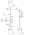
- FIG. 1 is a diagram illustrating the configuration of a flow path in which the hydroelectric power generation system according to the first embodiment is provided.
- FIG. 2 is a block diagram illustrating the configuration of the control unit.
- FIG. 3 is a graph illustrating a characteristic map of a hydroelectric power generation system.
- FIG. 4 is a flowchart illustrating the first control (flow rate control) in the first embodiment.
- FIG. 5 is a flowchart illustrating the second control (flow rate control) in the first embodiment.
- FIG. 6 is a flowchart illustrating the first control (head control) in the first embodiment.
- FIG. 7 is a flowchart illustrating the second control (head control) in the first embodiment.
- FIG. 1 is a diagram illustrating the configuration of a flow path in which the hydroelectric power generation system according to the first embodiment is provided.
- FIG. 2 is a block diagram illustrating the configuration of the control unit.
- FIG. 3 is a graph illustrating a characteristic map of a hydroelectric power generation system.
- FIG. 8 is a diagram illustrating the configuration of a flow path in which the hydroelectric power generation system according to the first modification of the first embodiment is provided.
- FIG. 9 is a diagram illustrating a configuration of a flow path provided with a hydroelectric power generation system according to a second modification of the first embodiment.
- FIG. 10 is a diagram illustrating a configuration of a flow path provided with a hydroelectric power generation system according to a modification 3 of the first embodiment.
- FIG. 11 is a diagram illustrating the configuration of a flow path in which the hydroelectric power generation system according to the second embodiment is provided.
- FIG. 12 is a flowchart illustrating the first control (flow rate control) in the second embodiment.
- FIG. 13 is a flowchart illustrating the second control (flow rate control) in the second embodiment.
- FIG. 14 is a diagram illustrating the configuration of a flow path in which the hydroelectric power generation system according to the third embodiment is provided.
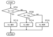
- FIG. 15 is a flowchart illustrating the first control (flow rate control) in the third embodiment.
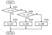
- FIG. 16 is a flowchart illustrating the second control (flow rate control) in the third embodiment.
- FIG. 17 is a graph illustrating integrated flow rate control of the hydroelectric power generation system according to the fourth embodiment.
- FIG. 18 is a diagram illustrating a modified example of the adjustment mechanism.
- FIG. 19 is a diagram for explaining estimation of pressure, flow rate, and liquid level.
- FIG. 20 is a graph for explaining the estimation of the liquid level.
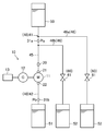
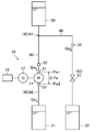
- FIG. 1 illustrates the configuration of the flow path (40) provided with the hydroelectric power generation system (10) according to the first embodiment.
- This hydroelectric power generation system (10) includes a water turbine (11), a generator (12), and a control unit (13).
- the turbine (11) is arranged in the flow path (40).
- the flow path (40) has a head.
- a fluid for example, water flows through the flow path (40).
- the flow path (40) includes a first flow path (41) and a second flow path (42).
- the flow path (40) is composed of a plurality of metal pipes (for example, ductile cast iron pipes).
- the flow path (40) is provided with a first storage tank (50), a second storage tank (51), and a branch storage tank (52).
- the first storage tank (50) drains the fluid into the first flow path (41). Fluid flows into the second storage tank (51) from the second flow path (42).
- the first flow path (41) is a flow path located on the inflow side of the water turbine (11).
- the first flow path (41) includes a turbine flow path (45) and a branch flow path (46).
- the water turbine flow path (45) is a flow path connecting the first storage tank (50) and the water turbine (11). At least a part of the fluid flowing into the turbine (11) flows through the turbine channel (45).
- the branch flow path (46) is a flow path that branches from the water turbine flow path (45).
- the branch flow path (46) is composed of a single flow path.
- a branch storage tank (52) is connected to the outlet of the branch flow path (46).
- the second flow path (42) is a flow path located on the outflow side of the water turbine (11).
- the second flow path (42) is composed of a single flow path.
- a second storage tank (51) is connected to the outlet of the second flow path (42).
- the turbine (11) is arranged in the flow path (40).
- the turbine (11) comprises an impeller and a casing that houses the impeller.
- an impeller provided in a centrifugal pump is used for the impeller.
- a rotating shaft is fixed to the center of the impeller.
- the impeller rotates under pressure due to the flow of fluid flowing into the casing from the inlet (inflow port) formed in the casing, and the rotating shaft rotates with the rotation of the impeller.
- the fluid in the casing is discharged from the outlet (outlet) formed in the casing.
- the generator (12) is driven by a water turbine (11). Specifically, the generator (12) is connected to the rotating shaft of the water turbine (11) and driven to rotate. Then, the generator (12) generates electricity by rotationally driving.
- the generator (12) includes a permanent magnet embedded roller and a stator having a coil.
- the turbine flow path (45) is provided with a flow meter (20).
- the flow meter (20) is arranged between the connection point between the turbine flow path (45) and the branch flow path (46) and the turbine (11) in the turbine flow path (45).
- the flow meter (20) detects the flow rate (Qw) of the water turbine (11) (specifically, the flow rate (Qw) of the fluid flowing through the water turbine (11)). Then, the flow meter (20) transmits a detection signal indicating the detection result (fluid flow rate (Qw)) to the control unit (13).
- a primary side pressure sensor (21) and a secondary side pressure sensor (22) are provided.
- the primary pressure sensor (21) is located at the inlet of the turbine (11) and the secondary pressure sensor (22) is located at the outlet of the turbine (11).
- the primary pressure sensor (21) detects the fluid pressure (Pw1) near the inlet of the turbine (11). In other words, the primary pressure sensor (21) detects the pressure (Pw1) of the fluid flowing into the turbine (11). Then, the primary pressure sensor (21) transmits a detection signal indicating the detection result (fluid pressure (Pw1)) to the control unit (13).
- the secondary pressure sensor (22) detects the fluid pressure (Pw2) near the outlet of the turbine (11). In other words, the secondary pressure sensor (22) detects the pressure (Pw2) of the fluid flowing out of the turbine (11). Then, the secondary pressure sensor (22) transmits a detection signal indicating the detection result (fluid pressure (Pw2)) to the control unit (13).
- the first pressure sensor (31a) is provided in the first flow path (41).
- the first pressure sensor (31a) detects the pressure (Pa) of the fluid in the first flow path (41). Then, the first pressure sensor (31a) transmits a detection signal indicating the detection result (pressure of the fluid (Pa) in the first flow path (41)) to the control unit (13).
- the first pressure sensor (31a) is provided in the branch flow path (46) which is part of the first flow path (41).
- a second pressure sensor (31b) is provided in the second flow path (42).
- the second pressure sensor (31b) detects the pressure (Pb) of the fluid in the second flow path (42). Then, the second pressure sensor (31b) transmits a detection signal indicating the detection result (pressure of the fluid (Pb) in the second flow path (42)) to the control unit (13).
- the branch flow path (46) is provided with an adjustment mechanism (60).
- the adjusting mechanism (60) regulates the flow rate or pressure of the fluid.
- the regulating mechanism (60) is a manual valve (61).
- the opening degree of the manual valve (61) may be fixed or variable.
- Control unit The control unit (13) is connected to each part of the hydroelectric power generation system (10) by a signal line, and signals transmitted from each part of the hydroelectric power generation system (10) (for example, detection signals of various sensors) and external instructions (for example). Each part of the hydroelectric power generation system (10) is controlled based on the target value).
- the control unit (13) controls the flow rate (Qw) or head ( ⁇ Pw) of the turbine (11). Specifically, the control unit (13) controls the flow rate (Qw) or head ( ⁇ Pw) of the water turbine (11) by controlling the torque or the rotation speed of the generator (12). Further, the control unit (13) can operate using the electric power obtained by the generator (12).
- control unit (13) can execute the first control and the second control.
- control unit (13) switches between the first control and the second control in response to an instruction from the outside.
- control unit (13) determines the flow rate (Qw) of the water turbine (11) so that the pressure (Pa) of the fluid in the first flow path (41) approaches the first target value in the first control. Or control the head ( ⁇ Pw). In addition, the control unit (13) determines the flow rate (Qw) or head (Qw) of the water turbine (11) so that the fluid pressure (Pb) in the second flow path (42) approaches the second target value in the second control. ⁇ Pw) is controlled.
- the first control and the second control will be described in detail later.
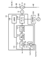
- FIG. 2 illustrates the configuration of the control unit (13).
- FIG. 2 illustrates the configuration of the control unit (13) that controls the flow rate (Qw) of the water turbine (11) by controlling the torque of the generator (12).
- the control unit (13) includes an AC / DC converter (100), a generator control unit (101), and a power storage unit (102).
- the AC / DC converter (100) has a plurality of switching elements, and converts the power (AC power) obtained by the power generation of the generator (12) into DC power by the switching operation.
- the output of the AC / DC converter (100) is smoothed by a smoothing capacitor and output to the grid interconnection inverter (201).
- the grid interconnection inverter (201) has a plurality of switching elements constituting the inverter unit. DC power from the AC / DC converter (100) is input to the grid interconnection inverter (201). In the grid interconnection inverter (201), DC power is converted into AC power by the switching operation of a plurality of switching elements.
- the AC power generated by the grid interconnection inverter (201) is supplied to the power grid (200).
- the electric power system (200) is a so-called commercial electric power system, and the hydroelectric power generation system (10) sells electric power by supplying electric power to the commercial electric power system (so-called reverse power flow).
- the generator control unit (101) is composed of, for example, a processor and a memory for storing programs and information for operating the processor.
- the generator control unit (101) has a target derivation unit (110), a torque calculation unit (111), a voltage calculation unit (112), and a converter control unit (113).
- Target derivation section In the first control, the target derivation unit (110) receives the fluid pressure (Pa) in the first flow path (41) and the first target pressure (Pa) corresponding to the target value of the pressure (Pa) in the first control. *) (An example of the first target value) is input.
- the target derivation unit (110) corresponds to the target value of the flow rate (Qw) of the water turbine (11) so that the pressure (Pa) of the fluid in the first flow path (41) approaches the first target pressure (Pa *). Derivation of the flow rate command value (Qw *) to be performed.
- the target derivation unit (110) receives the fluid pressure (Pb) in the second flow path (42) and the second target pressure corresponding to the target value of the pressure (Pb) in the second control. (Pb *) is entered.
- the target derivation unit (110) derives the flow rate command value (Qw *) so that the pressure (Pb) of the fluid in the second flow path (42) approaches the second target pressure (Pb *).
- Torque calculation unit >> The flow rate (Qw) of the water turbine (11) and the flow rate command value (Qw *) derived by the target derivation unit (110) are input to the torque calculation unit (111).
- the torque calculation unit (111) has a torque command value (T *) corresponding to the torque target value of the generator (12) so that the flow rate (Qw) of the water turbine (11) approaches the flow rate command value (Qw *). Is derived.
- the torque command value (T *) derived by the torque calculation unit (111) is input to the voltage calculation unit (112).
- the voltage calculation unit (112) derives the voltage command value (V *) based on the torque command value (T *).
- Converter control unit The converter control unit (113) PWM-controls the switching element of the AC / DC converter (100) based on the voltage command value (V *) derived by the voltage calculation unit (112). As a result, the flow rate (Qw) of the turbine (11) can be brought closer to the flow rate command value (Qw *).
- the power storage unit (102) stores the electric power obtained by the power generation of the generator (12).
- DC power from the AC / DC converter (100) is input to the power storage unit (102).
- the generator control unit (101) can operate using the electric power stored in the power storage unit (102).
- the operating parameters of the hydroelectric power generation system (10) and their relationships will be described in detail with reference to FIG.
- the vertical axis indicates the effective head (H) of the water turbine (11), and the horizontal axis indicates the flow rate (Q) flowing through the water turbine (11).
- the effective head (H) of the water turbine (11) is the first from the total head (Ho) between the liquid level of the first storage tank (50) and the liquid level of the second storage tank (51). The head corresponding to the pipeline resistance of the fluid in the storage tank (50) through the flow path (40) to the second storage tank (51) is reduced.
- the relationship between the effective head (H) and the flow rate (Q) can be represented by the flow resistance characteristic line (also referred to as the system loss curve (S)) shown in FIG.
- the curvature of the system loss curve (S) has a value peculiar to the flow path (40) in FIG.
- the flow rate (Q) in the flow path (40) including the hydroelectric power generation system (10) and the effective head (H) at that time correspond to the points on the system loss curve (S). That is, the point corresponding to the flow rate (Q) and the effective head (H) of the turbine (11) (the operating point of the turbine (11)) is always on the system loss curve (S).
- the torque value (T) of the generator (12) and the torque value (T) of the generator (12) are the characteristics that correlate with the flow rate (Q) and the effective head (H) in the water turbine (11). It represents the number of revolutions (rotational speed) (N) and the generated power (P) of the generator (12).
- a region (referred to as a turbine region or a operable region) in which the turbine (11) can be operated is formed between the curve (referred to as an operation limit curve) which is the minimum rotation speed of.
- the region on the left side of the unrestrained curve is the turbine brake region (power running region).
- the multiple equal torque curves follow the unrestrained curve, and the torque value (T) increases as the flow rate (Q) increases on the characteristic map (M).
- the plurality of constant rotation speed curves follow the operating limit curve, and the rotation speed (N) increases as the effective head (H) increases.
- the torque value (T) decreases as the flow rate (Q) decreases.
- the rotation speed (N) decreases as the flow rate (Q) increases.
- the equal power generation curve shown by the broken line is a downwardly convex curve, and the generated power (P) increases as the effective head (H) and the flow rate (Q) increase.
- each parameter of the characteristic map (M) as described above can be stored in the memory device in the form of a table (numerical table) or a mathematical formula (function) in the program. Therefore, the control unit (13) can perform various calculations and controls by using the relationship of each parameter represented by the characteristic map (M).
- Step (ST11)> The control unit (13) determines whether or not the pressure (Pa) of the fluid in the first flow path (41) exceeds the first target pressure (Pa *). For example, this determination is made by the target derivation unit (110). If the fluid pressure (Pa) in the first flow path (41) exceeds the first target pressure (Pa *), the process of step (ST13) is performed, and if not, the process of step (ST12) is performed. Will be done.
- Step (ST12)> The control unit (13) determines whether or not the pressure (Pa) of the fluid in the first flow path (41) is lower than the first target pressure (Pa *). For example, this determination is made by the target derivation unit (110). If the fluid pressure (Pa) in the first flow path (41) is lower than the first target pressure (Pa *), the process of step (ST14) is performed, and if not, the process of step (ST15) is performed. Will be done.
- the control unit (13) reduces the flow rate (Qw) of the water turbine (11).
- the target derivation unit (110) reduces the flow rate command value (Qw *).
- the flow rate (Qw) of the water turbine (11) decreases in this way, the fluid pressure (Pa) in the first flow path (41) increases, and the fluid pressure (Pa) in the first flow path (41) increases.
- Step (ST15)> When the pressure (Pa) of the fluid in the first flow path (41) matches the first target pressure (Pa *), the control unit (13) maintains the flow rate (Qw) of the water turbine (11). For example, the target derivation unit (110) maintains the flow rate command value (Qw *) unchanged. By maintaining the flow rate (Qw) of the water turbine (11) in this way, the pressure (Pa) of the fluid in the first flow path (41) is maintained.
- Step (ST21)> The control unit (13) determines whether or not the pressure (Pb) of the fluid in the second flow path (42) exceeds the second target pressure (Pb *). For example, this determination is made by the target derivation unit (110). If the fluid pressure (Pb) in the second flow path (42) exceeds the second target pressure (Pb *), the process of step (ST23) is performed, and if not, the process of step (ST22) is performed. Will be done.
- Step (ST22)> The control unit (13) determines whether or not the pressure (Pb) of the fluid in the second flow path (42) is lower than the second target pressure (Pb *). For example, this determination is made by the target derivation unit (110). If the fluid pressure (Pb) in the second flow path (42) is lower than the second target pressure (Pb *), the process of step (ST24) is performed, and if not, the process of step (ST25) is performed. Will be done.
- the control unit (13) controls the torque of the generator (12) to control the head ( ⁇ Pw) of the turbine (11) (specifically, the pressure of the fluid between the inlet and outlet of the turbine (11)).
- the difference may be configured to control.
- the target derivation unit (110) has a target value of the head ( ⁇ Pw) of the water turbine (11) so that the pressure (Pa) of the fluid in the first flow path (41) approaches the first target pressure (Pa *).
- the head command value corresponding to may be derived.
- the torque calculation unit (111) may derive a torque command value (T *) so that the head ( ⁇ Pw) of the water turbine (11) approaches the head command value.
- head control control of the head ( ⁇ Pw) of the water turbine (11)
- the target derivation unit (110) is a fluid near the outlet of the water wheel (11) so that the pressure (Pa) of the fluid in the first flow path (41) approaches the first target pressure (Pa *).
- the pressure command value which is the target value of the pressure (Pw2) of, is derived.
- the torque calculation unit (111) derives the torque command value (T *) so that the fluid pressure (Pw2) near the outlet of the water turbine (11) approaches the pressure command value.
- Step (ST11) The process of step (ST11) is performed in the same manner as in the first control shown in FIG. If the fluid pressure (Pa) in the first flow path (41) exceeds the first target pressure (Pa *), the process of step (ST16) is performed, and if not, the process of step (ST12) is performed. Will be done.
- Step (ST12)> The process of step (ST12) is performed in the same manner as in the first control shown in FIG. If the fluid pressure (Pa) in the first flow path (41) is lower than the first target pressure (Pa *), the process of step (ST17) is performed, and if not, the process of step (ST18) is performed. Will be done.
- the control unit (13) increases the fluid pressure (Pw2) near the outlet of the turbine (11).
- the target derivation unit (110) increases the pressure command value.
- the pressure of the fluid (Pw2) near the outlet of the turbine (11) increases (the head ( ⁇ Pw) of the turbine (11) decreases), so that the pressure of the fluid in the first flow path (41) ( Pa) decreases and the fluid pressure (Pa) in the first flow path (41) approaches the first target pressure (Pa *).
- ⁇ Step (ST17)> When the fluid pressure (Pa) in the first flow path (41) is lower than the first target pressure (Pa *), the control unit (13) reduces the fluid pressure (Pw2) near the outlet of the turbine (11). Let me. For example, the target derivation unit (110) reduces the pressure command value. In this way, the pressure of the fluid (Pw2) near the outlet of the turbine (11) decreases (the head ( ⁇ Pw) of the turbine (11) increases), so that the pressure of the fluid in the first flow path (41) ( Pa) increases and the fluid pressure (Pa) in the first flow path (41) approaches the first target pressure (Pa *).
- Step (ST21)> The process of step (ST21) is performed in the same manner as the second control shown in FIG. If the fluid pressure (Pb) in the second flow path (42) exceeds the second target pressure (Pb *), the process of step (ST26) is performed, and if not, the process of step (ST22) is performed. Will be done.
- Step (ST22)> The process of step (ST22) is performed in the same manner as the second control shown in FIG. If the fluid pressure (Pb) in the second flow path (42) is lower than the second target pressure (Pb *), the process of step (ST27) is performed, and if not, the process of step (ST28) is performed. Will be done.
- the control unit (13) controls the flow rate (Qw) or head ( ⁇ Pw) of the water turbine (11) by controlling the rotation speed of the generator (12) instead of controlling the torque of the generator (12). It may be configured to control. Specifically, the generator control unit (101) may have a rotation speed calculation unit (not shown) instead of the torque calculation unit (111). The rotation speed calculation unit derives a rotation speed command value corresponding to the target value of the rotation speed of the generator (12) so that the flow rate (Qw) of the water turbine (11) approaches the flow rate command value (Qw *).
- the rotation speed calculation unit rotates so that the head ( ⁇ Pw) of the water turbine (11) (for example, the pressure of the fluid near the outlet of the water turbine (11) (Pw2)) approaches the head command value (for example, the pressure command value). Derivation of several command values.
- the voltage calculation unit (112) may derive a voltage command value (V *) based on the rotation speed command value derived by the rotation speed calculation unit.
- the hydroelectric power generation system (10) of the first embodiment includes a water turbine (11) arranged in a flow path (40) through which a fluid flows, a generator (12) driven by the water turbine (11), and the like. It includes a control unit (13) that performs the first control.
- the flow path (40) includes a first flow path (41) located on the inflow side of the turbine (11).
- the control unit (13) sets the flow rate (Qw) or head ( ⁇ Pw) of the water turbine (11) so that the pressure (Pa) of the fluid in the first flow path (41) approaches the first target value. To control.
- One example) can be managed.
- the pressure (Pa) of the fluid in the first flow path (41) can be controlled to be constant, the stress applied to the piping constituting the first flow path (41) can be reduced. As a result, it is possible to suppress the occurrence of fluid leakage (for example, water leakage) in the first flow path (41).
- the control unit (13) can switch between the first control and the second control for execution.
- the flow path (40) includes a first flow path (41) and a second flow path (42) located on the outflow side of the turbine (11).
- the control unit (13) sets the flow rate (Qw) or head ( ⁇ Pw) of the water turbine (11) so that the pressure (Pb) of the fluid in the second flow path (42) approaches the second target value. To control.
- the pressure (Pb) of the fluid in the second flow path (42), which is the flow path on the outflow side of the water turbine (11), is in the state of the second flow path (42).
- Pb the pressure of the fluid in the second flow path (42), which is the flow path on the outflow side of the water turbine (11)
- One example can be managed.
- the first flow path (41) includes a water wheel flow path (45) through which at least a part of the fluid flowing into the water wheel (11) flows and a water wheel flow path (45). ) Includes a branch flow path (46).
- the pressure (Pb) of the fluid in the water turbine flow path (45) or the branch flow path (46) (the state of the water turbine flow path (45) or the branch flow path (46)).
- Pb the pressure of the fluid in the water turbine flow path (45) or the branch flow path (46)
- One example can be managed.
- control unit (13) is a hydroelectric power generation system characterized in that it can operate using the electric power obtained by the generator (12).
- the first control is performed even in the event of a power failure of the power system that supplies the electric power to the control unit (13). be able to.
- the branch flow path (46) may be composed of a plurality of flow paths.
- the branch flow path (46) is composed of a first branch flow path (46a) and a second branch flow path (46b).
- Each of the first branch flow path (46a) and the second branch flow path (46b) branches from the turbine flow path (45).
- each of the first branch flow path (46a) and the second branch flow path (46b) is provided with a manual valve (61) which is an example of the adjustment mechanism (60).
- a branch storage tank (52) is connected to each outlet of the first branch flow path (46a) and the second branch flow path (46b).
- the branch flow path (46) may branch into a plurality of flow paths.
- the branch flow path (46) is composed of a main flow path (46c), a first sub flow path (46d), and a second sub flow path (46e).
- the main flow path (46c) branches off from the turbine flow path (45).
- Each of the first sub-channel (46d) and the second sub-channel (46e) is connected to the outlet of the main channel (46c).
- each of the first sub-channel (46d) and the second sub-channel (46e) is provided with a manual valve (61) which is an example of the adjustment mechanism (60).
- a branch storage tank (52) is connected to each outlet of the first sub-channel (46d) and the second sub-channel (46e).
- the first flow path (41) may have no branch flow path (46) and only a water turbine flow path (45).
- the first flow path (41) may be composed of a single flow path.
- the first flow path (41) connects the first storage tank (50) and the water turbine (11).
- the control unit (13) has a flow rate (Qw) or a head ( ⁇ Pw) of the water turbine (11) so that the pressure of the fluid near the inlet of the adjustment mechanism (60) approaches the first target value. It may be the one that controls.
- the fluid pressure (Pa) in the first flow path (41) to be controlled in the first control may be the fluid pressure in the vicinity of the inlet of the adjusting mechanism (60).
- the flow rate (Qw) or head ( ⁇ Pw) of the water turbine (11) is controlled so that the pressure of the fluid near the inlet of the adjusting mechanism (60) approaches the first target value. Therefore, the controllability of the adjustment mechanism (60) can be improved. For example, so that the pressure of the fluid near the inlet of the adjusting mechanism (60) is within the range corresponding to the normal performance of the adjusting mechanism (60) (the range in which the normal capacity of the adjusting mechanism (60) can be drawn out).
- the flow rate (Qw) or head ( ⁇ Pw) of the turbine (11) the regular capacity of the adjustment mechanism (60) can be drawn out.
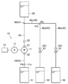
- FIG. 11 illustrates the configuration of the flow path (40) provided with the hydroelectric power generation system (10) according to the second embodiment.
- the first control and the second control by the control unit (13) are different from the hydroelectric power generation system (10) according to the first embodiment.
- a first flow rate sensor (32) is provided in place of the first pressure sensor (31a) and the second pressure sensor (31b).
- Other configurations of the hydroelectric power generation system (10) according to the second embodiment are the same as the configurations of the hydroelectric power generation system (10) according to the first embodiment.
- the first flow rate sensor (32) detects the flow rate (Qa) of the fluid in the first flow path (41).
- the first flow rate sensor (32) is provided in the branch flow path (46). Then, the first flow rate sensor (32) transmits a detection signal indicating the detection result (flow rate (Qa) of the fluid in the first flow path (41)) to the control unit (13).
- the control unit (13) determines the flow rate (Qw) of the water turbine (11) so that the flow rate (Qa) of the fluid in the first flow path (41) approaches the first target value in the first control. Or control the head ( ⁇ Pw).
- the target derivation unit (110) has a fluid flow rate (Qa) in the first flow path (41) and a fluid flow rate (Qa) in the first flow path (41).
- the first target flow rate (Qa *) corresponding to the target value (an example of the first target value) is input.
- the target derivation unit (110) derives a flow rate command value (Qw *) so that the flow rate (Qa) of the fluid in the first flow path (41) approaches the first target flow rate (Qa *).
- the control unit (13) determines the flow rate (11) of the water turbine (11) so that the flow rate (Qb) of the fluid in the second flow path (42) approaches the second target value in the second control.
- Qw) or head ( ⁇ Pw) is controlled.
- the target derivation unit (110) has the flow rate (Qb) of the fluid in the second flow path (42) and the flow rate (Qb) of the fluid in the second flow path (42).
- the second target flow rate (Qb *) (an example of the second target value) corresponding to the target value is input.
- the target derivation unit (110) derives a flow rate command value (Qw *) so that the flow rate (Qb) of the fluid in the second flow path (42) approaches the second target flow rate (Qb *).
- the flow rate (Qb) of the fluid in the second flow path (42) is the same as the flow rate (Qw) of the water turbine (11).
- the control unit (13) determines whether or not the flow rate (Qa) of the fluid in the first flow path (41) exceeds the first target flow rate (Qa *). For example, this determination is made by the target derivation unit (110). If the flow rate (Qa) of the fluid in the first flow path (41) exceeds the first target flow rate (Qa *), the process of step (ST13) is performed, and if not, the process of step (ST32) is performed. Will be done.
- the control unit (13) determines whether or not the flow rate (Qa) of the fluid in the first flow path (41) is lower than the first target flow rate (Qa *). For example, this determination is made by the target derivation unit (110). If the flow rate (Qa) of the fluid in the first flow path (41) is lower than the first target flow rate (Qa *), the process of step (ST14) is performed, and if not, the process of step (ST15) is performed. Will be done.
- the control unit (13) increases the flow rate (Qw) of the water turbine (11).
- the flow rate (Qa) of the fluid in the first flow path (41) decreases, and the flow rate (Qa) of the fluid in the first flow path (41) approaches the first target flow rate (Qa *).
- the control unit (13) reduces the flow rate (Qw) of the water turbine (11).
- the flow rate (Qa) of the fluid in the first flow path (41) increases, and the flow rate (Qa) of the fluid in the first flow path (41) approaches the first target flow rate (Qa *).
- Step (ST41)> The control unit (13) determines whether or not the flow rate (Qb) of the fluid in the second flow path (42) exceeds the second target flow rate (Qb *). For example, this determination is made by the target derivation unit (110). If the flow rate (Qb) of the fluid in the second flow path (42) exceeds the second target flow rate (Qb *), the process of step (ST23) is performed, and if not, the process of step (ST42) is performed. Will be done.
- Step (ST42)> The control unit (13) determines whether or not the flow rate (Qb) of the fluid in the second flow path (42) is lower than the second target flow rate (Qb *). For example, this determination is made by the target derivation unit (110). If the flow rate (Qb) of the fluid in the second flow path (42) is lower than the second target flow rate (Qb *), the process of step (ST24) is performed, and if not, the process of step (ST25) is performed. Will be done.
- control unit (13) is configured to control the head ( ⁇ Pw) of the water turbine (11) by controlling the torque of the generator (12). May be good.
- the control unit (13) controls the rotation speed of the generator (12) instead of controlling the torque of the generator (12) to control the water turbine (11).
- the control unit (13) May be configured to control the flow rate (Qw) or head ( ⁇ Pw).
- the hydroelectric power generation system (10) of the second embodiment includes a water turbine (11) arranged in a flow path (40) through which a fluid flows, a generator (12) driven by the water turbine (11), and the like. It includes a control unit (13) that performs the first control.
- the flow path (40) includes a first flow path (41) located on the inflow side of the turbine (11).
- the control unit (13) sets the flow rate (Qw) or head ( ⁇ Pw) of the water turbine (11) so that the flow rate (Qa) of the fluid in the first flow path (41) approaches the first target value. To control.
- One example) can be managed.
- the control unit (13) can switch between the first control and the second control for execution.
- the flow path (40) includes a first flow path (41) and a second flow path (42) located on the outflow side of the turbine (11).
- the control unit (13) sets the flow rate (Qw) or head ( ⁇ Pw) of the water turbine (11) so that the flow rate (Qb) of the fluid in the second flow path (42) approaches the second target value. To control.
- the flow rate (Qb) of the fluid in the second flow path (42), which is the flow path on the outflow side of the water turbine (11), is in the state of the second flow path (42).
- One example can be managed.
- the first flow path (41) includes a water wheel flow path (45) through which at least a part of the fluid flowing into the water wheel (11) flows and a water wheel flow path (45). ) Includes a branch flow path (46).
- the flow rate (Qb) of the fluid in the turbine flow path (45) or the branch flow path (46) (the state of the turbine flow path (45) or the branch flow path (46)).
- the flow rate (Qb) of the fluid in the turbine flow path (45) or the branch flow path (46) (the state of the turbine flow path (45) or the branch flow path (46)).
- One example can be managed.
- control unit (13) is a hydroelectric power generation system characterized in that it can operate using the electric power obtained by the generator (12).
- the first control is performed even in the event of a power failure of the power system that supplies the electric power to the control unit (13). be able to.
- the flow path (40) may have the configurations shown in FIGS. 8, 9, and 10.
- the branch flow path (46) may be composed of a plurality of flow paths, or the branch flow path (46) may be branched into a plurality of flow paths.
- the first flow path (41) may be composed of a single flow path.
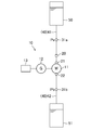
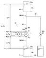
- FIG. 14 illustrates the configuration of the flow path (40) provided with the hydroelectric power generation system (10) according to the third embodiment.
- the first control and the second control by the control unit (13) are different from the hydroelectric power generation system (10) according to the first embodiment.
- the first liquid level sensor (33a) and the second liquid level sensor (33b) are replaced with the first pressure sensor (31a) and the second pressure sensor (31b). Is provided.
- Other configurations of the hydroelectric power generation system (10) according to the third embodiment are the same as the configurations of the hydroelectric power generation system (10) according to the first embodiment.
- the first liquid level sensor (33a) detects the liquid level (Ha) of the liquid in the first storage tank (50). Then, the first liquid level sensor (33a) transmits a detection signal indicating the detection result (the liquid level (Ha) of the liquid in the first storage tank (50)) to the control unit (13).
- the second liquid level sensor (33b) detects the liquid level (Hb) of the liquid in the second storage tank (51). Then, the second liquid level sensor (33b) transmits a detection signal indicating the detection result (the liquid level (Hb) of the liquid in the second storage tank (51)) to the control unit (13).
- the control unit (13) sets the liquid level (Ha) of the fluid in the first storage tank (50) that flows out to the first flow path (41) to the first target value. Control the flow rate (Qw) or head ( ⁇ Pw) of the water turbine (11) so that it approaches.
- the target derivation unit (110) has a fluid level (Ha) in the first storage tank (50) and a fluid level (Ha) in the first storage tank (50).
- the first target fluid level (an example of the first target value) corresponding to the target value of) is input.
- the target derivation unit (110) derives a flow rate command value (Qw *) so that the liquid level (Ha) of the fluid in the first storage tank (50) approaches the first target liquid level.
- the control unit (13) has a second target of the liquid level (Hb) of the fluid in the second storage tank (51) in which the fluid flows in from the second flow path (42). Control the flow rate (Qw) or head ( ⁇ Pw) of the turbine (11) so that it approaches the value.
- the target derivation unit (110) has a fluid level (Hb) in the second storage tank (51) and a fluid level (Hb) in the second storage tank (51).
- the second target fluid level (Hb *) (an example of the second target value) corresponding to the target value of) is input.
- the target derivation unit (110) derives a flow rate command value (Qw *) so that the liquid level (Hb) of the fluid in the second storage tank (51) approaches the second target liquid level (Hb *).
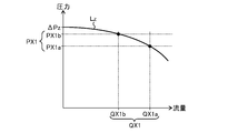
- the target derivation unit (110) derives the flow rate command value (Qw *) so that the total head ( ⁇ Pz) approaches the target total head ( ⁇ Pz *).
- the total head ( ⁇ Pz) is the head ( ⁇ P1) between the first storage tank (50) and the turbine (11), the head ( ⁇ Pw) of the turbine (11), and the turbine (11) and the second storage. It corresponds to the total with the head ( ⁇ P2) between the tank (51) and the tank (51).
- the liquid level (Hb) of the fluid in the second storage tank (51) is maintained at a constant value.
- ⁇ Step (ST51)> The control unit (13) determines whether or not the total head ( ⁇ Pz) exceeds the target total head ( ⁇ Pz *). For example, this determination is made by the target derivation unit (110). If the total head ( ⁇ Pz) exceeds the target total head ( ⁇ Pz *), the process of step (ST13) is performed, and if not, the process of step (ST52) is performed.
- ⁇ Step (ST52)> The control unit (13) determines whether or not the total head ( ⁇ Pz) is less than the target total head ( ⁇ Pz *). For example, this determination is made by the target derivation unit (110). If the total head ( ⁇ Pz) is less than the target total head ( ⁇ Pz *), the process of step (ST14) is performed, and if not, the process of step (ST15) is performed.
- the control unit (13) increases the flow rate (Qw) of the turbine (11).
- the total head ( ⁇ Pz) decreases, and the total head ( ⁇ Pz) approaches the target total head ( ⁇ Pz *).
- the liquid level (Ha) of the fluid in the first storage tank (50) decreases, and the liquid level (Ha) of the fluid in the first storage tank (50) approaches the first target liquid level.
- the control unit (13) reduces the flow rate (Qw) of the turbine (11).
- the total head ( ⁇ Pz) increases, and the total head ( ⁇ Pz) approaches the target total head ( ⁇ Pz *).
- the liquid level (Ha) of the fluid in the first storage tank (50) increases, and the liquid level (Ha) of the fluid in the first storage tank (50) approaches the first target liquid level.
- the control unit (13) maintains the flow rate (Qw) of the turbine (11).
- the total head ( ⁇ Pz) is maintained.
- the liquid level (Ha) of the fluid in the first storage tank (50) is maintained.
- the control unit (13) determines whether or not the liquid level (Hb) of the fluid in the second storage tank (51) exceeds the second target liquid level (Hb *). For example, this determination is made by the target derivation unit (110). If the liquid level (Hb) of the fluid in the second storage tank (51) exceeds the second target liquid level (Hb *), the treatment of step (ST23) is performed, and if not, the treatment of step (ST62) is performed. Processing is done.
- the control unit (13) determines whether or not the liquid level (Hb) of the fluid in the second storage tank (51) is lower than the second target liquid level (Hb *). For example, this determination is made by the target derivation unit (110). If the liquid level (Hb) of the fluid in the second storage tank (51) is lower than the second target liquid level (Hb *), the treatment of step (ST24) is performed, and if not, the treatment of step (ST25) is performed. Processing is done.
- control unit (13) is configured to control the head ( ⁇ Pw) of the water turbine (11) by controlling the torque of the generator (12). May be good.
- the control unit (13) controls the rotation speed of the generator (12) instead of controlling the torque of the generator (12) to control the water turbine (11).
- the control unit (13) May be configured to control the flow rate (Qw) or head ( ⁇ Pw).
- the hydroelectric power generation system (10) of the third embodiment includes a water turbine (11) arranged in a flow path (40) through which a fluid flows, a generator (12) driven by the water turbine (11), and the like. It includes a control unit (13) that performs the first control.
- the flow path (40) includes a first flow path (41) located on the inflow side of the turbine (11).
- the control unit (13) uses a water turbine so that the liquid level (Ha) of the fluid in the first storage tank (50) that flows out to the first flow path (41) approaches the first target value. Control the flow rate (Qw) or head ( ⁇ Pw) of (11).
- the position (Ha) (an example of the state of the first flow path (41)) can be managed.
- the liquid level (Ha) of the fluid in the first storage tank (50) can be controlled so that the first storage tank (50) is not emptied.
- the control unit (13) can switch between the first control and the second control for execution.
- the flow path (40) includes a first flow path (41) and a second flow path (42) located on the outflow side of the turbine (11).
- the control unit (13) uses a water turbine so that the liquid level (Hb) of the fluid in the second storage tank (51) into which the fluid flows from the second flow path (42) approaches the second target value. Control the flow rate (Qw) or head ( ⁇ Pw) of (11).
- the liquid level of the fluid in the second storage tank (51) in which the fluid flows in from the second flow path (42), which is the flow path on the outflow side of the water turbine (11), by performing the second control ( Hb) can be managed.
- the second storage tank (51) is about to be emptied, the second storage tank (51) is prevented from being emptied by switching from the first control to the second control. It is possible to control the liquid level (Hb) of the fluid in.
- the first flow path (41) includes a water wheel flow path (45) through which at least a part of the fluid flowing into the water wheel (11) flows and a water wheel flow path (45). ) Includes a branch flow path (46).
- the liquid level (Ha) water turbine flow path (45) or branch flow path (45) of the fluid in the first storage tank (50) that causes the fluid to flow out to the water turbine flow path (45) by performing the first control.
- An example of the state can be managed.
- control unit (13) is a hydroelectric power generation system characterized in that it can operate using the electric power obtained by the generator (12).
- the first control is performed even in the event of a power failure of the power system that supplies the electric power to the control unit (13). be able to.
- the flow path (40) may have the configurations shown in FIGS. 8, 9, and 10.
- the branch flow path (46) may be composed of a plurality of flow paths, or the branch flow path (46) may be branched into a plurality of flow paths.
- the first flow path (41) may be composed of a single flow path.
- the hydroelectric power generation systems of the first to third embodiments include the water turbine (11) arranged in the flow path (40) through which the fluid flows, the generator (12) driven by the water turbine (11), and the first. 1 It is provided with a control unit (13) that performs control.
- the flow path (40) includes a first flow path (41) located on the inflow side of the turbine (11).
- the control unit (13) determines the fluid pressure (Pa) in the first flow path (41), the fluid flow rate (Qa) in the first flow path (41), and the first flow path (41).
- the flow rate (Qw) or head ( ⁇ Pw) of the water turbine (11) is controlled so that any one of the fluid levels (Ha) in the first storage tank (50) outflowing the fluid approaches the first target value. ..
- the state of the first flow path (41), which is the flow path on the inflow side of the water turbine (11), can be managed by performing the first control.
- the control unit (13) can switch between the first control and the second control for execution.
- the flow path (40) includes a first flow path (41) and a second flow path (42) located on the outflow side of the turbine (11).
- the control unit (13) starts with the fluid pressure (Pb) in the second flow path (42), the fluid flow rate (Qb) in the second flow path (42), and the second flow path (42).
- the flow rate (Qw) or head ( ⁇ Pw) of the water turbine (11) is controlled so that any one of the fluid levels (Hb) in the second storage tank (51) into which the fluid flows approaches the second target value. ..
- the state of the second flow path (42), which is the flow path on the outflow side of the water turbine (11), can be managed by performing the second control.
- the first flow path (41) includes a water wheel flow path (45) through which at least a part of the fluid flowing into the water wheel (11) flows and a water wheel flow path. Includes a branch flow path (46) that branches from (45).
- the state of the turbine flow path (45) or the branch flow path (46) can be managed by performing the first control.
- control unit (13) controls the torque or the rotation speed of the generator (12) to control the flow rate (Qw) or head (Qw) of the water turbine (11). ⁇ Pw) is controlled.
- the branch flow path (46) is provided with an adjusting mechanism (60) for adjusting the flow rate or pressure of the fluid.
- a predetermined value may be set, a target range may be set, or an upper limit or a lower limit may be set.
- the operation of the control unit (13) is different from that of the hydroelectric power generation system (10) of the first to third embodiments.
- the control unit (13) performs the first control so that the integrated flow rate of the fluid in the branch flow path (46) approaches the target integrated flow rate.
- the other configurations of the hydroelectric power generation system (10) of the fourth embodiment are the same as the configurations of the hydroelectric power generation system (10) of the first to third embodiments.
- the first branch flow rate (Q1), the second branch flow rate (Q2), and the third branch flow rate (Q3) are the flow rates of the fluid in the branch flow path (46).
- the second branch flow rate (Q2) is larger than the first branch flow rate (Q1).
- the third branch flow rate (Q3) is larger than the second branch flow rate (Q2).
- the first turbine flow rate (Qw1), the second turbine flow rate (Qw2), and the third turbine flow rate (Qw3) are the flow rates (Qw) of the turbine (11).
- the second turbine flow rate (Qw2) is higher than the first turbine flow rate (Qw1).
- the third turbine flow rate (Qw3) is higher than the second turbine flow rate (Qw2).
- the first turbine flow rate (Qw1) is the same as the first branch flow rate (Q1)
- the second turbine flow rate (Qw2) is the same as the second branch flow rate (Q2)
- the third The turbine flow rate (Qw3) is the same as the third branch flow rate (Q3).
- the difference between the first branch flow rate (Q1) and the third branch flow rate (Q3) is the first flow rate difference ( ⁇ Q1).
- the difference between the second branch flow rate (Q2) and the third branch flow rate (Q3) is the second flow rate difference ( ⁇ Q2).
- the difference between the first turbine flow rate (Qw1) and the second turbine flow rate (Qw2) is also the second flow rate difference ( ⁇ Q2).
- the control period (P0) includes the adjustment period (P1).
- the adjustment period (P1) is a period including the end point of the control period (P0).
- the target integrated flow rate is set to Q3 ⁇ (P0-P1) + Q1 ⁇ P1.
- the control unit (13) has a flow rate of the fluid in the branch flow path (46).
- the first control is performed so that the third branch flow rate (Q3) is obtained.
- the flow rate (Qw) of the turbine (11) becomes the first turbine flow rate (Qw1).
- the flow rate of the fluid in the branch flow path (46) becomes the first branch flow rate (Q1) in the control unit (13).
- the first control is performed.
- the flow rate (Qw) of the turbine (11) becomes the third turbine flow rate (Qw3).
- the first control is interrupted during the period from the time (t11) to the time (t12), and the second control is performed.
- the control unit (13) performs the second control so that the flow rate (Qw) of the turbine (11) becomes the second turbine flow rate (Qw2) during the period from the time (t11) to the time (t12).
- the flow rate of the fluid in the branch flow path (46) becomes the second branch flow rate (Q2), which is smaller than the third branch flow rate (Q3).
- the control unit (13) first controls so that the flow rate of the fluid in the branch flow path (46) becomes the third branch flow rate (Q3). I do.
- the integrated flow rate of the fluid in the branch flow path (46) at the time (t13) is " ⁇ Q2 ⁇ ⁇ t1" less than the target integrated flow rate “Q3 ⁇ (P0-P1) + Q1 ⁇ P1”. ..
- the time ( ⁇ t1) is the time from the time (t11) to the time (t12).
- the control unit (13) branches from the start point of the adjustment period (P1) of the control period (P0) so that the following equation 1 holds.
- the time ( ⁇ t2) until the time when the flow rate of the fluid in the path (46) is changed from the third branch flow rate (Q3) to the first branch flow rate (Q1) is obtained.
- the branch flow path (46) is used in a place where the flow rate of the fluid in the branch flow path (46) is increased in the morning, noon, and night, and the flow rate (Qw) of the water wheel (11) is increased in the middle of the night. It is assumed that a contract has been concluded to supply the fluid to the branch flow path (46) so that the integrated flow rate of the fluid per day is constant. In such a place, if the liquid level of the fluid in the second storage tank (51) located on the outflow side of the turbine (11) suddenly drops in the daytime, the flow rate (Qw) of the turbine (11) even in the daytime. ) Needs to be increased temporarily.
- the integrated flow rate of the fluid in the branch flow path (46) per day may be insufficient. Therefore, by performing the integrated flow rate control as described above, even when the flow rate (Qw) of the water turbine (11) is temporarily increased in the daytime, the daily flow rate of the fluid in the branch flow path (46) is increased. It is possible to secure the integrated flow rate.
- control unit (13) performs the first control so that the integrated flow rate of the fluid in the branch flow path (46) approaches the target integrated flow rate.
- the integrated flow rate of the fluid in the branch flow path (46) can be managed.
- an electric valve (62) may be provided as the adjusting mechanism (60), or a pressure reducing valve may be provided.
- the first control is performed (specifically, the water turbine (specifically, the pressure of the fluid near the inlet of the electric valve (62) approaches the first target value).
- the controllability of the electric valve (62) can be improved.
- the first control reduces the pressure of the fluid near the inlet of the electric valve (62) to prevent cavitation in the electric valve (62). It can be avoided. As a result, a low-cost (low-performance) electric valve can be used as the electric valve (62). In addition, the service life of the electric valve (62) can be extended.
- Cavitation is a phenomenon (cavitation phenomenon) in which the pressure of the fluid drops to near the saturated vapor pressure due to the acceleration of the fluid inside the turbine (11), and a large number of vapor bubbles are generated. A large number of vapor bubbles are generated with the occurrence of cavitation, and when these vapor bubbles disappear, an extremely high pressure of tens of thousands of atmospheres is locally generated. As a result, the performance of the water turbine (11) is deteriorated, the surface of the water turbine (11) is eroded, and problems such as vibration and noise are generated.
- the control unit (13) uses the fluid pressure (Pa) in the first flow path (41), the fluid flow rate (Qa) in the first flow path (41), and the fluid level (50) in the first storage tank (50). It may be configured to estimate Ha).
- the first flow path (41) is composed of a water turbine flow path (45), a first branch flow path (46a), and a second branch flow path (46b).
- the branch storage tank (52) connected to the outlet of the first branch flow path (46a) will be referred to as “first branch storage tank (52a)” and will be connected to the outlet of the second branch flow path (46b).
- the branched water tank (52) to be used is referred to as a “second branch water tank (52b)”.
- the first connection point (71) is the connection point between the turbine flow path (45) and the first branch flow path (46a).
- the second connection point (72) is a connection point between the turbine flow path (45) and the second branch flow path (46b).
- the first point (X1) is a point located between the first storage tank (50) and the first connection point (71) of the turbine flow path (45).
- the second point (X2) is a point located in the middle of the first branch flow path (46a).
- the third point (X3) is a point located in the middle of the second branch flow path (46b).
- the pressure (P50) is the pressure of the fluid in the first storage tank (50).
- the pressure (PX1) is the pressure of the fluid at the first point (X1).
- the pressure (P71) is the pressure of the fluid at the first connection point (71).
- the pressure (P72) is the pressure of the fluid at the second connection point (72).
- the pressure (P51) is the pressure of the fluid in the second storage tank (51).
- the pressure difference ( ⁇ P70) is the pressure difference of the fluid between the first storage tank (50) and the first point (X1) of the turbine flow path (45).
- the pressure difference ( ⁇ P71) is the pressure difference of the fluid between the first point (X1) and the first connection point (71) of the turbine flow path (45).
- the pressure difference ( ⁇ P72) is the pressure difference of the fluid between the first connection point (71) and the second connection point (72) of the turbine flow path (45).
- the pressure difference ( ⁇ P73) is the pressure difference of the fluid between the second connection point (72) of the turbine flow path (45) and the turbine (11).
- the pressure difference ( ⁇ P74) is the pressure difference of the fluid between the turbine (11) and the second storage tank (51) of the turbine flow path (45).
- the pressure (PX2) is the pressure of the fluid at the second point (X2).
- the pressure (P52a) is the pressure of the fluid in the first branch storage tank (52a).
- the pressure difference ( ⁇ P75) is the pressure difference of the fluid between the first connection point (71) and the second point (X2) of the first branch flow path (46a).
- the pressure difference ( ⁇ P76) is the pressure difference of the fluid between the second point (X2) of the first branch flow path (46a) and the first branch storage tank (52a).
- the liquid level (Hd) is the liquid level of the fluid in the first branch storage tank (52a).
- the pressure (PX3) is the pressure of the fluid at the third point (X3).
- the pressure (P52b) is the pressure of the fluid in the second branch storage tank (52b).
- the pressure difference ( ⁇ P77) is the pressure difference of the fluid between the second connection point (72) and the third point (X3) of the second branch flow path (46b).
- the pressure difference ( ⁇ P78) is the pressure difference of the fluid between the third point (X3) of the second branch flow path (46b) and the second branch storage tank (52b).
- the liquid level (Hc) is the liquid level of the fluid in the second branch storage tank (52b).
- the flow rate (QX1) is the flow rate of the fluid between the first storage tank (50) and the first connection point (71) of the turbine flow path (45), and is the flow rate of the fluid flowing through the first point (X1). is there.
- the flow rate (Q70) is the flow rate of the fluid between the first connection point (71) and the second connection point (72) of the turbine flow path (45).
- the flow rate (QX2) is the flow rate of the fluid in the first branch flow path (46a), and is the flow rate of the fluid flowing through the second point (X2).
- the flow rate (QX3) is the flow rate of the fluid in the second branch flow path (46b), and is the flow rate of the fluid flowing through the third point (X3).
- the flow rate (Q70) corresponds to the sum of the flow rate (Qw) of the water turbine (11) and the flow rate (QX3) of the fluid in the second branch flow path (46b).
- the flow rate (QX1) corresponds to the sum of the flow rate (Q70) and the flow rate of the fluid (QX2) in the first branch flow path (46a).
- the flow rate (Qw) and head ( ⁇ Pw) of the turbine (11) can be estimated from the torque or rotation speed of the generator (12) from the characteristic map of the turbine (11) (see FIG. 3).
- the flow rate of the fluid flowing through the flow path between the two points and the flow path conditions between the two points can be estimated.
- the pressure difference (head) of the fluid between the two points can be estimated.
- the pressure difference ( ⁇ 71) can be estimated based on the flow rate (QX1) and the flow path condition between the first point (X1) and the first connection point (71). it can.
- the pressure difference (head) of the fluid between two points and the flow path condition (flow path length) between the two points.
- the flow rate of the fluid flowing through the flow path between the two points can be estimated.
- the flow rate (QX1) can be estimated based on the pressure difference ( ⁇ 71) and the flow path condition between the first point (X1) and the first connection point (71). it can.
- the fluid pressure (P51) in the second storage tank (51) becomes zero. Further, from the liquid level (Hb) of the fluid in the second storage tank (51), the flow path condition between the water turbine (11) and the second storage tank (51), and the flow rate (Qw) of the water turbine (11). , The pressure difference ( ⁇ P74) between the turbine (11) and the second storage tank (51) can be estimated. When the liquid level (Hb) is fixed, the pressure difference ( ⁇ P74) is based on the flow path conditions between the turbine (11) and the second storage tank (51) and the flow rate (Qw) of the turbine (11). Can be estimated.
- the liquid level sensor for measuring the liquid level (Hb) can be omitted.
- the same can be said for the first branch storage tank (52a) and the second branch storage tank (52b) as in the second storage tank (51).
- the pressure (P50) of the fluid in the first storage tank (50) can be estimated from the liquid level (Ha) of the fluid in the first storage tank (50).
- the pressure sensor for measuring the pressure of the fluid is provided in the water turbine flow path (45) or the second flow path (42) of the first flow path (41), the pressure sensor is a water turbine (from the viewpoint of reducing the installation cost). It is preferable to provide it near the entrance or the exit of 11). Further, from the viewpoint of reducing the installation cost, it is preferable that the pressure sensor is provided in the second flow path (42) rather than in the first flow path (41).
- control unit 1 Estimating fluid pressure
- the control unit (13) estimates that the pressure of the fluid at an arbitrary point included in the flow path (40) and the pressure (Pa) of the fluid at the first flow path (41) different from the arbitrary point and the arbitrary point should be estimated.
- To estimate the fluid pressure (Pa) in the first flow path (41) based on the flow path condition between the target point and the flow rate of the fluid in the flow path between the arbitrary point and the estimation target point. It may be configured in.
- the pressure to be estimated as the fluid pressure (Pa) in the first flow path (41) is the "pressure at the first point (X1) (PX1)", the pressure near the inlet of the water turbine (11) ( Pw1), the flow rate (Qw) of the water wheel (11), the flow rate (Q70) between the first connection point (71) and the second connection point (72), the first storage tank (50) and the first
- the pressure (PX1) at the first point (X1) can be estimated by the following equation 2.
- the pressure difference ( ⁇ P73) is estimated from the flow rate (Qw) of the turbine (11) and the flow path condition between the second connection point (72) and the turbine (11).
- the pressure difference ( ⁇ P72) is estimated from the flow rate (Q70) and the flow path conditions between the first connection point (71) and the second connection point (72).
- the pressure difference ( ⁇ P71) is estimated from the flow rate (QX1) and the flow path conditions between the first point (X1) and the first connection point (71).
- the estimation target point for estimating the fluid pressure (Pa) in the first flow path (41) is the "first point (X1)", and the arbitrary point included in the flow path (40) is ". It is a point near the entrance of the water turbine (11). "
- the pressure to be estimated as the pressure (Pa) of the fluid in the first flow path (41) is the "pressure (PX1) at the first point (X1)"
- the second storage tank (51) is open to the atmosphere.
- the pressure (P51) of the second storage tank (51) is zero.
- the pressure difference ( ⁇ P74) is the liquid level (Hb) of the second storage tank (51), the flow rate (Qw) of the water turbine (11), and the flow between the water turbine (11) and the second storage tank (51).
- the pressure difference ( ⁇ P73) is estimated from the flow rate (Qw) of the turbine (11) and the flow path condition between the second connection point (72) and the turbine (11).
- the pressure difference ( ⁇ P72) is estimated from the flow rate (Q70) and the flow path conditions between the first connection point (71) and the second connection point (72).
- the pressure difference ( ⁇ P71) is estimated from the flow rate (QX1) and the flow path conditions between the first point (X1) and the first connection point (71).
- the estimation target point for estimating the fluid pressure (Pa) in the first flow path (41) is the "first point (X1)", and the arbitrary point included in the flow path (40) is ". It is the point of the second storage tank (51).
- the pressure to be estimated as the fluid pressure (Pa) in the first flow path (41) is the "pressure at the third point (X3) (PX3)"
- the pressure near the outlet of the water turbine (11) When the flow rate (Qw) and head ( ⁇ Pw) of the water turbine (11) and the flow rate (QX3) of the second branch flow path (46b) are measured (or estimated), the following equation 4 is used.
- the pressure (PX3) at the third point (X3) can be estimated.
- PX3 Pw2 + ⁇ Pw + ⁇ P73- ⁇ P77... Equation 4
- the pressure difference ( ⁇ P73) is estimated from the flow rate (Qw) of the turbine (11) and the flow path condition between the second connection point (72) and the turbine (11).
- the pressure difference ( ⁇ P77) is estimated from the flow rate (QX3) and the flow path conditions between the second connection point (72) and the third point (X3).
- the estimation target point for estimating the fluid pressure (Pa) in the first flow path (41) is the "third point (X3)", and the arbitrary point included in the flow path (40) is ". It is a point near the exit of the water turbine (11). "
- the pressure (Pa) of the fluid in the first flow path (41) is performed by the same procedure as described above. ) Can be estimated.
- the control unit (13) has the pressure of the fluid at the arbitrary point included in the flow path (40) and the first flow path (41) different from the arbitrary point and the arbitrary point.
- the first flow path (41) is based on the flow path condition between the estimation target point for which the fluid pressure (Pa) should be estimated and the flow rate of the fluid in the flow rate between the arbitrary point and the estimation target point. Estimate the pressure (Pa) of the fluid in.
- control unit (13) uses the first flow path (41) based on the flow rate of the fluid at an arbitrary point different from the estimation target point at which the flow rate (Qa) of the fluid in the first flow path (41) should be estimated. It may be configured to estimate the flow rate (Qa) of the fluid in. Alternatively, the control unit (13) determines the fluid pressure at the estimation target point where the fluid flow rate (Qa) in the first flow path (41) should be estimated, and the fluid pressure at an arbitrary point different from the estimation target point. It may be configured to estimate the flow rate (Qa) of the fluid in the first flow path (41) based on the flow path condition between the estimation target point and the arbitrary point.
- the flow rate to be estimated as the flow rate (Qa) of the fluid in the first flow path (41) is the "flow rate (QX2) at the second point (X2)", the first storage tank (50) and the first
- the flow rate (QX2) at the second point (X2) can be estimated by the following equation 5.
- the estimation target point to be estimated as the fluid flow rate (Qa) in the first flow path (41) is the "third point (X3)", and the arbitrary point different from the estimation target point is the "first”. "Any point between the storage tank (50) and the first connection point (71)", “A point where the turbine (11) is placed” and "Any point of the second branch flow path (46b)”. ..
- the flow rate to be estimated as the flow rate (Qa) of the fluid in the first flow path (41) is the "flow rate (QX3) at the third point (X3)"
- the pressure near the inlet of the water wheel (11) When the flow rate (Qw) of the water wheel (11) and the pressure (PX3) of the third point (X3) are measured (or estimated), the second connection point (72) is measured by the following equation 6.
- the pressure difference ( ⁇ P77) between and the third point (X3) is estimated.
- ⁇ P77 (Pw1 + ⁇ P73) -PX3... Equation 6
- the pressure difference ( ⁇ P73) is estimated from the flow rate (Qw) of the turbine (11) and the flow path condition between the second connection point (72) and the turbine (11).
- “Pw1 + ⁇ P73” corresponds to the pressure (P72) at the second connection point (72).
- the flow rate (QX3) at the third point (X3) can be estimated.
- the estimation target point to be estimated as the fluid flow rate (Qa) in the first flow path (41) is the "third point (X3)", and the arbitrary point different from the estimation target point is the "second". Connection point (72) ".
- the flow rate (Qa) of the fluid in the first flow path (41) is performed by the same procedure as described above. ) Can be estimated.
- the control unit (13) is based on the flow rate of the fluid at an arbitrary point different from the estimation target point at which the flow rate (Qa) of the fluid in the first flow path (41) should be estimated.
- the flow rate (Qa) of the fluid in the first flow path (41) is estimated.
- the control unit (13) determines the fluid pressure at the estimation target point where the fluid flow rate (Qa) in the first flow path (41) should be estimated, and the fluid pressure at an arbitrary point different from the estimation target point.
- the flow rate (Qa) of the fluid in the first flow path (41) is estimated based on the flow path conditions between the estimation target point and the arbitrary point.
- control unit (13) has a first control unit (13) based on a pressure corresponding to a different flow rate of the fluid at an arbitrary point located between the first storage tank (50) and the water turbine (11) in the flow path (40). It may be configured to estimate the liquid level (Ha) of the fluid in the reservoir (50).
- the loss curve (Lz) can be estimated based on the change in pressure (PX1) according to the change in fluid flow rate (QX1) at the first point (X1). Specifically, the first pressure (PX1a), which is the fluid pressure (PX1) when the fluid flow rate (QX1) at the first point (X1) is the first flow rate (QX1a), and the first point (X1). ), The loss curve (Lz) can be drawn based on the second pressure (PX1b) which is the pressure (PX1) of the fluid when the flow rate (QX1) of the fluid is the second flow rate (QX1b).
- the first flow rate (QX1a) and the second flow rate (QX1b) may be, for example, a flow rate obtained by changing the liquid level (Ha) of the fluid in the first storage tank (50), or may be an arbitrary flow rate.
- the flow rate may be obtained by changing.
- the pressure when the flow rate (QX1) is zero on the loss curve (Lz) corresponds to the total head ( ⁇ Pz).
- the total head that does not depend on the liquid level (Ha) of the fluid in the first storage tank (50) and the liquid level (Hb) of the fluid in the second storage tank (51) be the "reference total head ( ⁇ Pz0)".
- the liquid level (Ha) of the fluid in the first storage tank (50) is expressed by the following equation 7.
- the reference total head ( ⁇ Pz0) can be estimated from the flow path conditions between the first storage tank (50) and the second storage tank (51).
- the loss curve (Lz) can be estimated from the change in the flow rate (QX1) at the first point (X1) and the change in the pressure (PX1) at the first point (X1).
- the total head ( ⁇ Pz) can be estimated from (Lz).
- the liquid level (Ha) of the first storage tank (50) is estimated from the total head ( ⁇ Pz), the reference total head ( ⁇ Pz0), and the liquid level (Hb) of the second storage tank (51). Can be done.
- the arbitrary point located between the first storage tank (50) and the water turbine (11) in the flow path (40) is the "first point (X1)".
- the fluid pressure (PX1) at the first point (X1) may be estimated by the same procedure as in the first modification of the control unit.
- the flow rate of the fluid (QX1) at the first point (X1) may be estimated by the same procedure as in the second modification of the control unit.
- the liquid level of the fluid in the first storage tank (50) is determined by the same procedure as described above. Ha) can be estimated.
- control unit (13) has a different flow rate of the fluid at an arbitrary point located between the first storage tank (50) and the water turbine (11) in the flow path (40).
- the liquid level (Ha) of the fluid in the first storage tank (50) is estimated based on the corresponding pressure.
- the water turbine (11) has better responsiveness than the electric valve. Therefore, the pressure (Pa) of the fluid in the first flow path (41) (or the flow rate (Qa) of the fluid in the first flow path (41), and the first storage tank in which the fluid flows out to the first flow path (41).
- the water wheel (11) can quickly respond to the steep change, so when controlling using an electric valve Rather than the pressure (Pa) of the fluid in the first flow path (41) (or the flow rate (Qa) of the fluid in the first flow path (41), the first storage in which the fluid flows out to the first flow path (41). It is possible to suppress abrupt changes in the liquid level (Ha) of the fluid in the tank (50).
- this disclosure is useful as a hydroelectric power generation system.
- Hydraulic power generation system 11 Water wheel 12 Generator 13 Control unit 21 Primary side pressure sensor 22 Secondary side pressure sensor 31a First pressure sensor 31b Second pressure sensor 32 First flow sensor 33a First liquid level sensor 33b Second liquid level sensor 40 Flow path 41 First flow path 42 Second flow path 45 Water wheel flow path 46 Branch flow path 50 First storage tank 51 Second storage tank 60 Adjustment mechanism
Abstract
水車(11)は、流体が流れる流路(40)に配置される。発電機(12)は、水車(11)により駆動される。制御部(13)は、第1制御を行う。流路(40)は、水車(11)の流入側に位置する第1流路(41)を含む。制御部(13)は、第1制御において、第1流路(41)における流体の圧力(Pa)、第1流路(41)における流体の流量(Qa)、第1流路(41)に流体を流出する第1貯留槽(50)における流体の液位(Ha)のいずれか1つが第1目標値に近づくように、水車(11)の流量(Qw)または落差(ΔPw)を制御する。
Description
本開示は、水力発電システムに関する。
特許文献1には、水力発電システムが開示されている。この水力発電システムは、流体が流れる流路に配置される水車と、水車によって駆動される発電機と、水車の有効落差を調節する落差調節手段と、制御部とを備える。制御部は、水車の流量が目標流量に近づくように発電機を制御する流量制御と、水車の有効落差を第1範囲内とするように落差調節手段によって水車の有効落差を調節する落差調節制御とを協調して行う。
しかしながら、特許文献1のシステムでは、水車の流出側における流路の状態を管理することができるが、水車の流入側における流路の状態を管理することが困難である。
本開示の第1の態様は、水力発電システムに関し、この水力発電システムは、流体が流れる流路(40)に配置される水車(11)と、前記水車(11)により駆動される発電機(12)と、第1制御を行う制御部(13)とを備え、前記流路(40)は、前記水車(11)の流入側に位置する第1流路(41)を含み、前記制御部(13)は、前記第1制御において、前記第1流路(41)における前記流体の圧力(Pa)、前記第1流路(41)における前記流体の流量(Qa)、前記第1流路(41)に前記流体を流出する第1貯留槽(50)における前記流体の液位(Ha)のいずれか1つが第1目標値に近づくように、前記水車(11)の流量(Qw)または落差(ΔPw)を制御する。
第1の態様では、第1制御を行うことにより、水車(11)の流入側における流路である第1流路(41)の状態を管理することができる。
本開示の第2の態様は、第1の態様において、前記制御部(13)は、前記発電機(12)のトルクまたは回転数を制御することで前記水車(11)の流量(Qw)または落差(ΔPw)を制御することを特徴とする水力発電システムである。
本開示の第3の態様は、第1または第2の態様において、前記制御部(13)は、前記第1制御と、第2制御とを実行可能であり、前記流路(40)は、前記第1流路(41)と、前記水車(11)の流出側に位置する第2流路(42)とを含み、前記制御部(13)は、前記第2制御において、前記第2流路(42)における前記流体の圧力(Pb)、前記第2流路(42)における前記流体の流量(Qb)、前記第2流路(42)から前記流体が流入する第2貯留槽(51)における前記流体の液位(Hb)のいずれか1つが第2目標値に近づくように、前記水車(11)の流量(Qw)または落差(ΔPw)を制御することを特徴とする水力発電システムである。
第3の態様では、第2制御を行うことにより、水車(11)の流出側における流路である第2流路(42)の状態を管理することができる。
本開示の第4の態様は、第1~第3の態様のいずれか1つにおいて、前記第1流路(41)は、前記水車(11)に流入する前記流体の少なくとも一部が流れる水車流路(45)と、前記水車流路(45)から分岐する分岐流路(46)とを含むことを特徴とする水力発電システムである。
第4の態様では、第1制御を行うことにより、水車流路(45)または分岐流路(46)の状態を管理することができる。
本開示の第5の態様は、第4の態様において、前記制御部(13)は、前記分岐流路(46)における前記流体の積算流量が目標積算流量に近づくように、前記第1制御を行うことを特徴とする水力発電システムである。
第5の態様では、分岐流路(46)における流体の積算流量を管理することができる。
本開示の第6の態様は、第4または第5の態様において、前記分岐流路(46)には、前記流体の流量または圧力を調節する調節機構(60)が設けられることを特徴とする水力発電システムである。
本開示の第7の態様は、第6の態様において、前記制御部(13)は、前記第1制御において、前記調節機構(60)の入口近傍における前記流体の圧力が前記第1目標値に近づくように、前記水車(11)の流量(Qw)または落差(ΔPw)を制御することを特徴とする水力発電システムである。
第7の態様では、第1制御を行うことにより、調節機構(60)の制御性を向上させることができる。
本開示の第8の態様は、第1~第7の態様のいずれか1つにおいて、前記制御部(13)は、前記流路(40)に含まれる任意地点における前記流体の圧力と、前記任意地点と前記任意地点とは異なる前記第1流路(41)における前記流体の圧力(Pa)を推定すべき推定対象地点との間の流路条件と、前記任意地点と前記推定対象地点の間の流路における前記流体の流量とに基づいて、前記第1流路(41)における前記流体の圧力(Pa)を推定することを特徴とする水力発電システムである。
第8の態様では、第1流路(41)における流体の圧力(Pa)を検出する圧力センサを設けなくてもよいので、設置コストを低減することができる。
本開示の第9の態様は、第1~第7の態様のいずれか1つにおいて、前記制御部(13)は、前記流路(40)において前記第1貯留槽(50)と前記水車(11)との間に位置する任意地点における前記流体の異なる流量に応じた圧力に基づいて、前記第1貯留槽(50)における前記流体の液位(Ha)を推定することを特徴とする水力発電システムである。
第9の態様では、第1貯留槽(50)における流体の液位(Ha)を検出する液位センサを設けなくてもよいので、設置コストを低減することができる。
本開示の第10の態様は、第4~第7の態様のいずれか1つにおいて、前記制御部(13)は、前記第1流路(41)における前記流体の流量(Qa)を推定すべき推定対象地点とは異なる任意地点における前記流体の流量に基づいて、前記第1流路(41)における前記流体の流量(Qa)を推定することを特徴とする水力発電システムである。
本開示の第11の態様は、第4~第7の態様のいずれか1つにおいて、前記制御部(13)は、前記第1流路(41)における前記流体の流量(Qa)を推定すべき推定対象地点における前記流体の圧力と、前記推定対象地点とは異なる任意地点における前記流体の圧力と、前記推定対象地点と前記任意地点との間の流路条件とに基づいて、前記第1流路(41)における前記流体の流量(Qa)を推定することを特徴とする水力発電システムである。
第10および第11の態様では、第1流路(41)における流体の流量(Qa)を検出する流量センサを設けなくてもよいので、設置コストを低減することができる。
本開示の第12の態様は、第1~第11の態様のいずれか1つにおいて、前記制御部(13)は、前記発電機(12)により得られる電力を用いて動作可能であることを特徴とする水力発電システムである。
第12の態様では、発電機(12)により得られる電力を用いて制御部(13)を動作させることにより、制御部(13)に電力を供給する電力系統の停電時においても第1制御を行うことができる。
以下、実施の形態を図面を参照して詳しく説明する。なお、図中同一または相当部分には同一の符号を付しその説明は繰り返さない。
(実施形態1)
図1は、実施形態1による水力発電システム(10)が設けられる流路(40)の構成を例示する。この水力発電システム(10)は、水車(11)と、発電機(12)と、制御部(13)とを備える。水車(11)は、流路(40)に配置される。
図1は、実施形態1による水力発電システム(10)が設けられる流路(40)の構成を例示する。この水力発電システム(10)は、水車(11)と、発電機(12)と、制御部(13)とを備える。水車(11)は、流路(40)に配置される。
〔流路〕
流路(40)は、落差を有する。流路(40)には、流体(例えば水)が流れる。流路(40)は、第1流路(41)と、第2流路(42)とを含む。例えば、流路(40)は、複数の金属管(例えばダクタイル鋳鉄管)により構成される。また、この例では、流路(40)には、第1貯留槽(50)と第2貯留槽(51)と分岐貯留槽(52)とが設けられる。第1貯留槽(50)は、第1流路(41)に流体を流出する。第2貯留槽(51)には、第2流路(42)から流体が流入する。
流路(40)は、落差を有する。流路(40)には、流体(例えば水)が流れる。流路(40)は、第1流路(41)と、第2流路(42)とを含む。例えば、流路(40)は、複数の金属管(例えばダクタイル鋳鉄管)により構成される。また、この例では、流路(40)には、第1貯留槽(50)と第2貯留槽(51)と分岐貯留槽(52)とが設けられる。第1貯留槽(50)は、第1流路(41)に流体を流出する。第2貯留槽(51)には、第2流路(42)から流体が流入する。
〈第1流路〉
第1流路(41)は、水車(11)の流入側に位置する流路である。この例では、第1流路(41)は、水車流路(45)と、分岐流路(46)とを含む。水車流路(45)は、第1貯留槽(50)と水車(11)とを繋ぐ流路である。水車流路(45)には、水車(11)に流入する流体の少なくとも一部が流れる。分岐流路(46)は、水車流路(45)から分岐する流路である。この例では、分岐流路(46)は、単一の流路により構成される。また、分岐流路(46)の出口には、分岐貯留槽(52)が接続される。
第1流路(41)は、水車(11)の流入側に位置する流路である。この例では、第1流路(41)は、水車流路(45)と、分岐流路(46)とを含む。水車流路(45)は、第1貯留槽(50)と水車(11)とを繋ぐ流路である。水車流路(45)には、水車(11)に流入する流体の少なくとも一部が流れる。分岐流路(46)は、水車流路(45)から分岐する流路である。この例では、分岐流路(46)は、単一の流路により構成される。また、分岐流路(46)の出口には、分岐貯留槽(52)が接続される。
〈第2流路〉
第2流路(42)は、水車(11)の流出側に位置する流路である。この例では、第2流路(42)は、単一の流路により構成される。第2流路(42)の出口には、第2貯留槽(51)が接続される。
第2流路(42)は、水車(11)の流出側に位置する流路である。この例では、第2流路(42)は、単一の流路により構成される。第2流路(42)の出口には、第2貯留槽(51)が接続される。
〔水車〕
水車(11)は、流路(40)に配置される。この例では、水車(11)は、羽根車と、羽根車を収容するケーシングとを備える。例えば、羽根車には、渦巻きポンプに備えるインペラが用いられる。羽根車の中心部には、回転軸が固定される。水車(11)では、ケーシングに形成された入口(流入口)からケーシング内に流入した流体の流れにより羽根車が圧力を受けて回転し、羽根車の回転とともに回転軸が回転する。ケーシング内の流体は、ケーシングに形成された出口(流出口)から排出される。
水車(11)は、流路(40)に配置される。この例では、水車(11)は、羽根車と、羽根車を収容するケーシングとを備える。例えば、羽根車には、渦巻きポンプに備えるインペラが用いられる。羽根車の中心部には、回転軸が固定される。水車(11)では、ケーシングに形成された入口(流入口)からケーシング内に流入した流体の流れにより羽根車が圧力を受けて回転し、羽根車の回転とともに回転軸が回転する。ケーシング内の流体は、ケーシングに形成された出口(流出口)から排出される。
〔発電機〕
発電機(12)は、水車(11)により駆動される。具体的には、発電機(12)は、水車(11)の回転軸に連結されて回転駆動される。そして、発電機(12)は、回転駆動により発電を行う。例えば、発電機(12)は、永久磁石埋込型のローラと、コイルを有するステータとを備える。
発電機(12)は、水車(11)により駆動される。具体的には、発電機(12)は、水車(11)の回転軸に連結されて回転駆動される。そして、発電機(12)は、回転駆動により発電を行う。例えば、発電機(12)は、永久磁石埋込型のローラと、コイルを有するステータとを備える。
〔流量計〕
この例では、水車流路(45)には、流量計(20)が設けられる。流量計(20)は、水車流路(45)において水車流路(45)と分岐流路(46)との接続点と水車(11)との間に配置される。流量計(20)は、水車(11)の流量(Qw)(具体的には水車(11)を流れる流体の流量(Qw))を検出する。そして、流量計(20)は、検出結果(流体の流量(Qw))を示す検出信号を制御部(13)に送信する。
この例では、水車流路(45)には、流量計(20)が設けられる。流量計(20)は、水車流路(45)において水車流路(45)と分岐流路(46)との接続点と水車(11)との間に配置される。流量計(20)は、水車(11)の流量(Qw)(具体的には水車(11)を流れる流体の流量(Qw))を検出する。そして、流量計(20)は、検出結果(流体の流量(Qw))を示す検出信号を制御部(13)に送信する。
〔圧力センサ〕
また、この例では、一次側圧力センサ(21)と、二次側圧力センサ(22)とが設けられる。この例では、一次側圧力センサ(21)は、水車(11)の入口に配置され、二次側圧力センサ(22)は、水車(11)の出口に配置される。
また、この例では、一次側圧力センサ(21)と、二次側圧力センサ(22)とが設けられる。この例では、一次側圧力センサ(21)は、水車(11)の入口に配置され、二次側圧力センサ(22)は、水車(11)の出口に配置される。
〈一次側圧力センサ〉
一次側圧力センサ(21)は、水車(11)の入口近傍における流体の圧力(Pw1)を検出する。言い換えると、一次側圧力センサ(21)は、水車(11)に流入する流体の圧力(Pw1)を検出する。そして、一次側圧力センサ(21)は、検出結果(流体の圧力(Pw1))を示す検出信号を制御部(13)に送信する。
一次側圧力センサ(21)は、水車(11)の入口近傍における流体の圧力(Pw1)を検出する。言い換えると、一次側圧力センサ(21)は、水車(11)に流入する流体の圧力(Pw1)を検出する。そして、一次側圧力センサ(21)は、検出結果(流体の圧力(Pw1))を示す検出信号を制御部(13)に送信する。
〈二次側圧力センサ〉
二次側圧力センサ(22)は、水車(11)の出口近傍における流体の圧力(Pw2)を検出する。言い換えると、二次側圧力センサ(22)は、水車(11)から流出する流体の圧力(Pw2)を検出する。そして、二次側圧力センサ(22)は、検出結果(流体の圧力(Pw2))を示す検出信号を制御部(13)に送信する。
二次側圧力センサ(22)は、水車(11)の出口近傍における流体の圧力(Pw2)を検出する。言い換えると、二次側圧力センサ(22)は、水車(11)から流出する流体の圧力(Pw2)を検出する。そして、二次側圧力センサ(22)は、検出結果(流体の圧力(Pw2))を示す検出信号を制御部(13)に送信する。
〔第1圧力センサ〕
また、この例では、第1流路(41)には、第1圧力センサ(31a)が設けられる。第1圧力センサ(31a)は、第1流路(41)における流体の圧力(Pa)を検出する。そして、第1圧力センサ(31a)は、検出結果(第1流路(41)における流体の圧力(Pa))を示す検出信号を制御部(13)に送信する。この例では、第1圧力センサ(31a)は、第1流路(41)の一部である分岐流路(46)に設けられる。
また、この例では、第1流路(41)には、第1圧力センサ(31a)が設けられる。第1圧力センサ(31a)は、第1流路(41)における流体の圧力(Pa)を検出する。そして、第1圧力センサ(31a)は、検出結果(第1流路(41)における流体の圧力(Pa))を示す検出信号を制御部(13)に送信する。この例では、第1圧力センサ(31a)は、第1流路(41)の一部である分岐流路(46)に設けられる。
〔第2圧力センサ〕
また、この例では、第2流路(42)には、第2圧力センサ(31b)が設けられる。第2圧力センサ(31b)は、第2流路(42)における流体の圧力(Pb)を検出する。そして、第2圧力センサ(31b)は、検出結果(第2流路(42)における流体の圧力(Pb))を示す検出信号を制御部(13)に送信する。
また、この例では、第2流路(42)には、第2圧力センサ(31b)が設けられる。第2圧力センサ(31b)は、第2流路(42)における流体の圧力(Pb)を検出する。そして、第2圧力センサ(31b)は、検出結果(第2流路(42)における流体の圧力(Pb))を示す検出信号を制御部(13)に送信する。
〔調節機構〕
また、この例では、分岐流路(46)には、調節機構(60)が設けられる。調節機構(60)は、流体の流量または圧力を調節する。この例では、調節機構(60)は、手動弁(61)である。なお、手動弁(61)の開度は、固定であってもよいし、可変であってもよい。
また、この例では、分岐流路(46)には、調節機構(60)が設けられる。調節機構(60)は、流体の流量または圧力を調節する。この例では、調節機構(60)は、手動弁(61)である。なお、手動弁(61)の開度は、固定であってもよいし、可変であってもよい。
〔制御部〕
制御部(13)は、水力発電システム(10)の各部と信号線により接続され、水力発電システム(10)の各部から送信された信号(例えば各種センサの検出信号)と外部からの指示(例えば目標値)などに基づいて、水力発電システム(10)の各部を制御する。
制御部(13)は、水力発電システム(10)の各部と信号線により接続され、水力発電システム(10)の各部から送信された信号(例えば各種センサの検出信号)と外部からの指示(例えば目標値)などに基づいて、水力発電システム(10)の各部を制御する。
制御部(13)は、水車(11)の流量(Qw)または落差(ΔPw)を制御する。具体的には、制御部(13)は、発電機(12)のトルクまたは回転数を制御することで水車(11)の流量(Qw)または落差(ΔPw)を制御する。また、制御部(13)は、発電機(12)により得られる電力を用いて動作可能である。
また、この例では、制御部(13)は、第1制御と、第2制御とを実行可能である。例えば、制御部(13)は、外部からの指示に応答して第1制御と第2制御とを切り換える。
実施形態1では、制御部(13)は、第1制御において、第1流路(41)における流体の圧力(Pa)が第1目標値に近づくように、水車(11)の流量(Qw)または落差(ΔPw)を制御する。また、制御部(13)は、第2制御において、第2流路(42)における流体の圧力(Pb)が第2目標値に近づくように、水車(11)の流量(Qw)または落差(ΔPw)を制御する。第1制御および第2制御については、後で詳しく説明する。
〔制御部の構成〕
図2は、制御部(13)の構成を例示する。図2には、発電機(12)のトルクを制御することで水車(11)の流量(Qw)を制御する制御部(13)の構成が例示されている。制御部(13)は、AC/DCコンバータ(100)と、発電機制御部(101)と、蓄電部(102)とを有する。
図2は、制御部(13)の構成を例示する。図2には、発電機(12)のトルクを制御することで水車(11)の流量(Qw)を制御する制御部(13)の構成が例示されている。制御部(13)は、AC/DCコンバータ(100)と、発電機制御部(101)と、蓄電部(102)とを有する。
〈AC/DCコンバータ〉
AC/DCコンバータ(100)は、複数のスイッチング素子を有し、発電機(12)の発電により得られた電力(交流電力)をスイッチング動作により直流電力に変換する。AC/DCコンバータ(100)の出力は、平滑コンデンサにより平滑化され、系統連系インバータ(201)に出力される。
AC/DCコンバータ(100)は、複数のスイッチング素子を有し、発電機(12)の発電により得られた電力(交流電力)をスイッチング動作により直流電力に変換する。AC/DCコンバータ(100)の出力は、平滑コンデンサにより平滑化され、系統連系インバータ(201)に出力される。
〈系統連系インバータ〉
系統連系インバータ(201)は、インバータ部を構成する複数のスイッチング素子を有する。系統連系インバータ(201)には、AC/DCコンバータ(100)からの直流電力が入力される。系統連系インバータ(201)では、複数のスイッチング素子のスイッチング動作により直流電力が交流電力に変換される。系統連系インバータ(201)により生成された交流電力は、電力系統(200)に供給される。例えば、電力系統(200)は、いわゆる商用電力系統であり、水力発電システム(10)では、商用電力系統への電力供給(いわゆる逆潮流)により、いわゆる売電を行う。
系統連系インバータ(201)は、インバータ部を構成する複数のスイッチング素子を有する。系統連系インバータ(201)には、AC/DCコンバータ(100)からの直流電力が入力される。系統連系インバータ(201)では、複数のスイッチング素子のスイッチング動作により直流電力が交流電力に変換される。系統連系インバータ(201)により生成された交流電力は、電力系統(200)に供給される。例えば、電力系統(200)は、いわゆる商用電力系統であり、水力発電システム(10)では、商用電力系統への電力供給(いわゆる逆潮流)により、いわゆる売電を行う。
〈発電機制御部〉
発電機制御部(101)は、例えば,プロセッサと、プロセッサを動作させるためのプログラムや情報を記憶するメモリとにより構成される。この例では、発電機制御部(101)は、目標導出部(110)と、トルク演算部(111)と、電圧演算部(112)と、コンバータ制御部(113)とを有する。
発電機制御部(101)は、例えば,プロセッサと、プロセッサを動作させるためのプログラムや情報を記憶するメモリとにより構成される。この例では、発電機制御部(101)は、目標導出部(110)と、トルク演算部(111)と、電圧演算部(112)と、コンバータ制御部(113)とを有する。
《目標導出部》
第1制御において、目標導出部(110)には、第1流路(41)における流体の圧力(Pa)と、第1制御における圧力(Pa)の目標値に相当する第1目標圧力(Pa*)(第1目標値の一例)とが入力される。目標導出部(110)は、第1流路(41)における流体の圧力(Pa)が第1目標圧力(Pa*)に近づくように、水車(11)の流量(Qw)の目標値に相当する流量指令値(Qw*)を導出する。
第1制御において、目標導出部(110)には、第1流路(41)における流体の圧力(Pa)と、第1制御における圧力(Pa)の目標値に相当する第1目標圧力(Pa*)(第1目標値の一例)とが入力される。目標導出部(110)は、第1流路(41)における流体の圧力(Pa)が第1目標圧力(Pa*)に近づくように、水車(11)の流量(Qw)の目標値に相当する流量指令値(Qw*)を導出する。
また、第2制御において、目標導出部(110)には、第2流路(42)における流体の圧力(Pb)と、第2制御における圧力(Pb)の目標値に相当する第2目標圧力(Pb*)とが入力される。目標導出部(110)は、第2流路(42)における流体の圧力(Pb)が第2目標圧力(Pb*)に近づくように、流量指令値(Qw*)を導出する。
《トルク演算部》
トルク演算部(111)には、水車(11)の流量(Qw)と、目標導出部(110)により導出された流量指令値(Qw*)とが入力される。トルク演算部(111)は、水車(11)の流量(Qw)が流量指令値(Qw*)に近づくように、発電機(12)のトルクの目標値に相当するトルク指令値(T*)を導出する。
トルク演算部(111)には、水車(11)の流量(Qw)と、目標導出部(110)により導出された流量指令値(Qw*)とが入力される。トルク演算部(111)は、水車(11)の流量(Qw)が流量指令値(Qw*)に近づくように、発電機(12)のトルクの目標値に相当するトルク指令値(T*)を導出する。
《電圧演算部》
電圧演算部(112)には、トルク演算部(111)により導出されたトルク指令値(T*)が入力される。電圧演算部(112)は、トルク指令値(T*)に基づいて電圧指令値(V*)を導出する。
電圧演算部(112)には、トルク演算部(111)により導出されたトルク指令値(T*)が入力される。電圧演算部(112)は、トルク指令値(T*)に基づいて電圧指令値(V*)を導出する。
《コンバータ制御部》
コンバータ制御部(113)は、電圧演算部(112)により導出された電圧指令値(V*)に基づいて、AC/DCコンバータ(100)のスイッチング素子をPWM制御する。これにより、水車(11)の流量(Qw)を流量指令値(Qw*)に近づけることができる。
コンバータ制御部(113)は、電圧演算部(112)により導出された電圧指令値(V*)に基づいて、AC/DCコンバータ(100)のスイッチング素子をPWM制御する。これにより、水車(11)の流量(Qw)を流量指令値(Qw*)に近づけることができる。
〈蓄電部〉
蓄電部(102)は、発電機(12)の発電により得られた電力を蓄える。この例では、蓄電部(102)には、AC/DCコンバータ(100)からの直流電力が入力される。発電機制御部(101)は、蓄電部(102)に蓄えられた電力を用いて動作可能である。
蓄電部(102)は、発電機(12)の発電により得られた電力を蓄える。この例では、蓄電部(102)には、AC/DCコンバータ(100)からの直流電力が入力される。発電機制御部(101)は、蓄電部(102)に蓄えられた電力を用いて動作可能である。
〔水力発電システムの運転パラメータ〕
次に、図3を参照しながら、水力発電システム(10)の運転パラメータとこれらの関係について詳細に説明する。図3に示すグラフ(特性マップ(M)ともいう)において、縦軸は、水車(11)の有効落差(H)を示し、横軸は、水車(11)を流れる流量(Q)を示す。ここで、水車(11)での有効落差(H)は、第1貯留槽(50)の液面から第2貯留槽(51)の液面までの間の総落差(Ho)から、第1貯留槽(50)の流体が流路(40)を経て第2貯留槽(51)に至るまでの管路抵抗に相当する落差を減じたものである。
次に、図3を参照しながら、水力発電システム(10)の運転パラメータとこれらの関係について詳細に説明する。図3に示すグラフ(特性マップ(M)ともいう)において、縦軸は、水車(11)の有効落差(H)を示し、横軸は、水車(11)を流れる流量(Q)を示す。ここで、水車(11)での有効落差(H)は、第1貯留槽(50)の液面から第2貯留槽(51)の液面までの間の総落差(Ho)から、第1貯留槽(50)の流体が流路(40)を経て第2貯留槽(51)に至るまでの管路抵抗に相当する落差を減じたものである。
有効落差(H)と流量(Q)との関係は、図3に示す流動抵抗特性線(システムロスカーブ(S)ともいう)で表すことができる。システムロスカーブ(S)は、流量(Q)=0のときの有効落差(H)が総落差(Ho)であり、流量(Q)の増大に応じて有効落差(H)が二次曲線的に減少する特性を持つ。システムロスカーブ(S)の曲率は、図1の流路(40)に固有の値を持つ。水力発電システム(10)を含む流路(40)における流量(Q)とその際の有効落差(H)とは、システムロスカーブ(S)上の点に対応する。すなわち、水車(11)の流量(Q)と有効落差(H)に対応する点(水車(11)の運転点)は、常にシステムロスカーブ(S)上にある。
図3の特性マップ(M)では、水車(11)における流量(Q)と有効落差(H)とに相関する特性として、発電機(12)のトルク値(T)、発電機(12)の回転数(回転速度)(N)、発電機(12)の発電電力(P)を表している。
特性マップ(M)では、発電機(12)のトルク値(T)が0の曲線(無拘束曲線(T=0)という)と、発電機(12)の回転数(N)が0または所定の最低回転数となる曲線(動作限界曲線という)との間に、水車(11)が運転可能な領域(水車領域ないし運転可能領域という)が形成される。図3において、無拘束曲線よりも左側の領域は、水車ブレーキ領域(力行領域)である。
水車領域において、複数の等トルク曲線は、無拘束曲線に沿い、特性マップ(M)上、流量(Q)の増大に応じてトルク値(T)も増大する。また、複数の等回転速度曲線は、動作限界曲線に沿い、有効落差(H)が大きくなるほど回転数(N)も上昇する。システムロスカーブ(S)上においては、流量(Q)の減少に応じてトルク値(T)が減少する。また、システムロスカーブ(S)上においては、流量(Q)の増大に応じて回転数(N)が減少する。破線で示した等発電電力曲線は、下に凸な曲線であり、有効落差(H)および流量(Q)の増大に応じて発電電力(P)も増大する。
以上のような特性マップ(M)の各パラメータの関係は、テーブル(数表)や、プログラム内の数式(関数)という形でメモリディバイスに格納可能である。したがって、制御部(13)は、特性マップ(M)で表される各パラメータの関係を利用することで、各種の演算や制御を行うことができる。
〔第1制御(流量制御)〕
次に、図4を参照しながら、実施形態1における制御部(13)の第1制御について説明する。以下では、第1制御において流量制御(水車(11)の流量(Qw)の制御)が行われる場合を例に挙げて説明する。
次に、図4を参照しながら、実施形態1における制御部(13)の第1制御について説明する。以下では、第1制御において流量制御(水車(11)の流量(Qw)の制御)が行われる場合を例に挙げて説明する。
〈ステップ(ST11)〉
制御部(13)は、第1流路(41)における流体の圧力(Pa)が第1目標圧力(Pa*)を上回るか否かを判定する。例えば、この判定は、目標導出部(110)で行われる。第1流路(41)における流体の圧力(Pa)が第1目標圧力(Pa*)を上回る場合にはステップ(ST13)の処理が行われ、そうでない場合にはステップ(ST12)の処理が行われる。
制御部(13)は、第1流路(41)における流体の圧力(Pa)が第1目標圧力(Pa*)を上回るか否かを判定する。例えば、この判定は、目標導出部(110)で行われる。第1流路(41)における流体の圧力(Pa)が第1目標圧力(Pa*)を上回る場合にはステップ(ST13)の処理が行われ、そうでない場合にはステップ(ST12)の処理が行われる。
〈ステップ(ST12)〉
制御部(13)は、第1流路(41)における流体の圧力(Pa)が第1目標圧力(Pa*)を下回るか否かを判定する。例えば、この判定は、目標導出部(110)で行われる。第1流路(41)における流体の圧力(Pa)が第1目標圧力(Pa*)を下回る場合にはステップ(ST14)の処理が行われ、そうでない場合にはステップ(ST15)の処理が行われる。
制御部(13)は、第1流路(41)における流体の圧力(Pa)が第1目標圧力(Pa*)を下回るか否かを判定する。例えば、この判定は、目標導出部(110)で行われる。第1流路(41)における流体の圧力(Pa)が第1目標圧力(Pa*)を下回る場合にはステップ(ST14)の処理が行われ、そうでない場合にはステップ(ST15)の処理が行われる。
〈ステップ(ST13)〉
第1流路(41)における流体の圧力(Pa)が第1目標圧力(Pa*)を上回る場合、制御部(13)は、水車(11)の流量(Qw)を増加させる。例えば、目標導出部(110)は、流量指令値(Qw*)を増加させる。このように、水車(11)の流量(Qw)が増加することにより、第1流路(41)における流体の圧力(Pa)が減少し、第1流路(41)における流体の圧力(Pa)が第1目標圧力(Pa*)に近づく。
第1流路(41)における流体の圧力(Pa)が第1目標圧力(Pa*)を上回る場合、制御部(13)は、水車(11)の流量(Qw)を増加させる。例えば、目標導出部(110)は、流量指令値(Qw*)を増加させる。このように、水車(11)の流量(Qw)が増加することにより、第1流路(41)における流体の圧力(Pa)が減少し、第1流路(41)における流体の圧力(Pa)が第1目標圧力(Pa*)に近づく。
〈ステップ(ST14)〉
第1流路(41)における流体の圧力(Pa)が第1目標圧力(Pa*)を下回る場合、制御部(13)は、水車(11)の流量(Qw)を減少させる。例えば、目標導出部(110)は、流量指令値(Qw*)を減少させる。このように、水車(11)の流量(Qw)が減少することにより、第1流路(41)における流体の圧力(Pa)が増加し、第1流路(41)における流体の圧力(Pa)が第1目標圧力(Pa*)に近づく。
第1流路(41)における流体の圧力(Pa)が第1目標圧力(Pa*)を下回る場合、制御部(13)は、水車(11)の流量(Qw)を減少させる。例えば、目標導出部(110)は、流量指令値(Qw*)を減少させる。このように、水車(11)の流量(Qw)が減少することにより、第1流路(41)における流体の圧力(Pa)が増加し、第1流路(41)における流体の圧力(Pa)が第1目標圧力(Pa*)に近づく。
〈ステップ(ST15)〉
第1流路(41)における流体の圧力(Pa)が第1目標圧力(Pa*)と一致する場合、制御部(13)は、水車(11)の流量(Qw)を維持する。例えば、目標導出部(110)は、流量指令値(Qw*)を変更せずに維持する。このように、水車(11)の流量(Qw)が維持されることにより、第1流路(41)における流体の圧力(Pa)が維持される。
第1流路(41)における流体の圧力(Pa)が第1目標圧力(Pa*)と一致する場合、制御部(13)は、水車(11)の流量(Qw)を維持する。例えば、目標導出部(110)は、流量指令値(Qw*)を変更せずに維持する。このように、水車(11)の流量(Qw)が維持されることにより、第1流路(41)における流体の圧力(Pa)が維持される。
〔第2制御(流量制御)〕
次に、図5を参照しながら、実施形態12における制御部(13)の第2制御について説明する。以下では、第2制御において流量制御(水車(11)の流量(Qw)の制御)が行われる場合を例に挙げて説明する。
次に、図5を参照しながら、実施形態12における制御部(13)の第2制御について説明する。以下では、第2制御において流量制御(水車(11)の流量(Qw)の制御)が行われる場合を例に挙げて説明する。
〈ステップ(ST21)〉
制御部(13)は、第2流路(42)における流体の圧力(Pb)が第2目標圧力(Pb*)を上回るか否かを判定する。例えば、この判定は、目標導出部(110)で行われる。第2流路(42)における流体の圧力(Pb)が第2目標圧力(Pb*)を上回る場合にはステップ(ST23)の処理が行われ、そうでない場合にはステップ(ST22)の処理が行われる。
制御部(13)は、第2流路(42)における流体の圧力(Pb)が第2目標圧力(Pb*)を上回るか否かを判定する。例えば、この判定は、目標導出部(110)で行われる。第2流路(42)における流体の圧力(Pb)が第2目標圧力(Pb*)を上回る場合にはステップ(ST23)の処理が行われ、そうでない場合にはステップ(ST22)の処理が行われる。
〈ステップ(ST22)〉
制御部(13)は、第2流路(42)における流体の圧力(Pb)が第2目標圧力(Pb*)を下回るか否かを判定する。例えば、この判定は、目標導出部(110)で行われる。第2流路(42)における流体の圧力(Pb)が第2目標圧力(Pb*)を下回る場合にはステップ(ST24)の処理が行われ、そうでない場合にはステップ(ST25)の処理が行われる。
制御部(13)は、第2流路(42)における流体の圧力(Pb)が第2目標圧力(Pb*)を下回るか否かを判定する。例えば、この判定は、目標導出部(110)で行われる。第2流路(42)における流体の圧力(Pb)が第2目標圧力(Pb*)を下回る場合にはステップ(ST24)の処理が行われ、そうでない場合にはステップ(ST25)の処理が行われる。
〈ステップ(ST23)〉
第2流路(42)における流体の圧力(Pb)が第2目標圧力(Pb*)を上回る場合、制御部(13)は、水車(11)の流量(Qw)を減少させる。例えば、目標導出部(110)は、流量指令値(Qw*)を減少させる。このように、水車(11)の流量(Qw)が減少することにより、第2流路(42)における流体の圧力(Pb)が減少し、第2流路(42)における流体の圧力(Pb)が第2目標圧力(Pb*)に近づく。
第2流路(42)における流体の圧力(Pb)が第2目標圧力(Pb*)を上回る場合、制御部(13)は、水車(11)の流量(Qw)を減少させる。例えば、目標導出部(110)は、流量指令値(Qw*)を減少させる。このように、水車(11)の流量(Qw)が減少することにより、第2流路(42)における流体の圧力(Pb)が減少し、第2流路(42)における流体の圧力(Pb)が第2目標圧力(Pb*)に近づく。
〈ステップ(ST24)〉
第2流路(42)における流体の圧力(Pb)が第2目標圧力(Pb*)を下回る場合、制御部(13)は、水車(11)の流量(Qw)を増加させる。例えば、目標導出部(110)は、流量指令値(Qw*)を増加させる。このように、水車(11)の流量(Qw)が増加することにより、第2流路(42)における流体の圧力(Pb)が増加し、第2流路(42)における流体の圧力(Pb)が第2目標圧力(Pb*)に近づく。
第2流路(42)における流体の圧力(Pb)が第2目標圧力(Pb*)を下回る場合、制御部(13)は、水車(11)の流量(Qw)を増加させる。例えば、目標導出部(110)は、流量指令値(Qw*)を増加させる。このように、水車(11)の流量(Qw)が増加することにより、第2流路(42)における流体の圧力(Pb)が増加し、第2流路(42)における流体の圧力(Pb)が第2目標圧力(Pb*)に近づく。
〈ステップ(ST25)〉
第2流路(42)における流体の圧力(Pb)が第2目標圧力(Pb*)と一致する場合、制御部(13)は、水車(11)の流量(Qw)を維持する。例えば、目標導出部(110)は、流量指令値(Qw*)を変更せずに維持する。このように、水車(11)の流量(Qw)が維持されることにより、第2流路(42)における流体の圧力(Pb)が維持される。
第2流路(42)における流体の圧力(Pb)が第2目標圧力(Pb*)と一致する場合、制御部(13)は、水車(11)の流量(Qw)を維持する。例えば、目標導出部(110)は、流量指令値(Qw*)を変更せずに維持する。このように、水車(11)の流量(Qw)が維持されることにより、第2流路(42)における流体の圧力(Pb)が維持される。
〔落差制御〕
なお、制御部(13)は、発電機(12)のトルクを制御することで水車(11)の落差(ΔPw)(具体的には水車(11)の入口と出口との間における流体の圧力差)を制御するように構成されてもよい。例えば、目標導出部(110)は、第1流路(41)における流体の圧力(Pa)が第1目標圧力(Pa*)に近づくように、水車(11)の落差(ΔPw)の目標値に相当する落差指令値を導出してもよい。トルク演算部(111)は、水車(11)の落差(ΔPw)が落差指令値に近づくように、トルク指令値(T*)を導出してもよい。
なお、制御部(13)は、発電機(12)のトルクを制御することで水車(11)の落差(ΔPw)(具体的には水車(11)の入口と出口との間における流体の圧力差)を制御するように構成されてもよい。例えば、目標導出部(110)は、第1流路(41)における流体の圧力(Pa)が第1目標圧力(Pa*)に近づくように、水車(11)の落差(ΔPw)の目標値に相当する落差指令値を導出してもよい。トルク演算部(111)は、水車(11)の落差(ΔPw)が落差指令値に近づくように、トルク指令値(T*)を導出してもよい。
〔第1制御(落差制御)〕
次に、図6を参照しながら、実施形態1の制御部(13)の第1制御において落差制御(水車(11)の落差(ΔPw)の制御)が行われる場合について説明する。以下では、水車(11)の出口近傍における流体の圧力(Pw2)を制御することで水車(11)の落差(ΔPw)を制御する場合を例に挙げて説明する。具体的には、目標導出部(110)は、第1流路(41)における流体の圧力(Pa)が第1目標圧力(Pa*)に近づくように、水車(11)の出口近傍における流体の圧力(Pw2)の目標値である圧力指令値を導出する。トルク演算部(111)は、水車(11)の出口近傍における流体の圧力(Pw2)が圧力指令値に近づくように、トルク指令値(T*)を導出する。
次に、図6を参照しながら、実施形態1の制御部(13)の第1制御において落差制御(水車(11)の落差(ΔPw)の制御)が行われる場合について説明する。以下では、水車(11)の出口近傍における流体の圧力(Pw2)を制御することで水車(11)の落差(ΔPw)を制御する場合を例に挙げて説明する。具体的には、目標導出部(110)は、第1流路(41)における流体の圧力(Pa)が第1目標圧力(Pa*)に近づくように、水車(11)の出口近傍における流体の圧力(Pw2)の目標値である圧力指令値を導出する。トルク演算部(111)は、水車(11)の出口近傍における流体の圧力(Pw2)が圧力指令値に近づくように、トルク指令値(T*)を導出する。
〈ステップ(ST11)〉
図4に示した第1制御と同様に、ステップ(ST11)の処理が行われる。第1流路(41)における流体の圧力(Pa)が第1目標圧力(Pa*)を上回る場合にはステップ(ST16)の処理が行われ、そうでない場合にはステップ(ST12)の処理が行われる。
図4に示した第1制御と同様に、ステップ(ST11)の処理が行われる。第1流路(41)における流体の圧力(Pa)が第1目標圧力(Pa*)を上回る場合にはステップ(ST16)の処理が行われ、そうでない場合にはステップ(ST12)の処理が行われる。
〈ステップ(ST12)〉
図4に示した第1制御と同様に、ステップ(ST12)の処理が行われる。第1流路(41)における流体の圧力(Pa)が第1目標圧力(Pa*)を下回る場合にはステップ(ST17)の処理が行われ、そうでない場合にはステップ(ST18)の処理が行われる。
図4に示した第1制御と同様に、ステップ(ST12)の処理が行われる。第1流路(41)における流体の圧力(Pa)が第1目標圧力(Pa*)を下回る場合にはステップ(ST17)の処理が行われ、そうでない場合にはステップ(ST18)の処理が行われる。
〈ステップ(ST16)〉
第1流路(41)における流体の圧力(Pa)が第1目標圧力(Pa*)を上回る場合、制御部(13)は、水車(11)の出口近傍における流体の圧力(Pw2)を増加させる。例えば、目標導出部(110)は、圧力指令値を増加させる。このように、水車(11)の出口近傍における流体の圧力(Pw2)が増加する(水車(11)の落差(ΔPw)が減少する)ことにより、第1流路(41)における流体の圧力(Pa)が減少し、第1流路(41)における流体の圧力(Pa)が第1目標圧力(Pa*)に近づく。
第1流路(41)における流体の圧力(Pa)が第1目標圧力(Pa*)を上回る場合、制御部(13)は、水車(11)の出口近傍における流体の圧力(Pw2)を増加させる。例えば、目標導出部(110)は、圧力指令値を増加させる。このように、水車(11)の出口近傍における流体の圧力(Pw2)が増加する(水車(11)の落差(ΔPw)が減少する)ことにより、第1流路(41)における流体の圧力(Pa)が減少し、第1流路(41)における流体の圧力(Pa)が第1目標圧力(Pa*)に近づく。
〈ステップ(ST17)〉
第1流路(41)における流体の圧力(Pa)が第1目標圧力(Pa*)を下回る場合、制御部(13)は、水車(11)の出口近傍における流体の圧力(Pw2)を減少させる。例えば、目標導出部(110)は、圧力指令値を減少させる。このように、水車(11)の出口近傍における流体の圧力(Pw2)が減少する(水車(11)の落差(ΔPw)が増加する)ことにより、第1流路(41)における流体の圧力(Pa)が増加し、第1流路(41)における流体の圧力(Pa)が第1目標圧力(Pa*)に近づく。
第1流路(41)における流体の圧力(Pa)が第1目標圧力(Pa*)を下回る場合、制御部(13)は、水車(11)の出口近傍における流体の圧力(Pw2)を減少させる。例えば、目標導出部(110)は、圧力指令値を減少させる。このように、水車(11)の出口近傍における流体の圧力(Pw2)が減少する(水車(11)の落差(ΔPw)が増加する)ことにより、第1流路(41)における流体の圧力(Pa)が増加し、第1流路(41)における流体の圧力(Pa)が第1目標圧力(Pa*)に近づく。
〈ステップ(ST18)〉
第1流路(41)における流体の圧力(Pa)が第1目標圧力(Pa*)と一致する場合、制御部(13)は、水車(11)の出口近傍における流体の圧力(Pw2)を維持する。例えば、目標導出部(110)は、圧力指令値を変更せずに維持する。このように、水車(11)の出口近傍における流体の圧力(Pw2)(水車(11)の落差(ΔPw))が維持されることにより、第1流路(41)における流体の圧力(Pa)が維持される。
第1流路(41)における流体の圧力(Pa)が第1目標圧力(Pa*)と一致する場合、制御部(13)は、水車(11)の出口近傍における流体の圧力(Pw2)を維持する。例えば、目標導出部(110)は、圧力指令値を変更せずに維持する。このように、水車(11)の出口近傍における流体の圧力(Pw2)(水車(11)の落差(ΔPw))が維持されることにより、第1流路(41)における流体の圧力(Pa)が維持される。
〔第2制御(落差制御)〕
次に、図7を参照しながら、実施形態1の制御部(13)の第2制御において落差制御(水車(11)の落差(ΔPw)の制御)が行われる場合について説明する。以下では、水車(11)の出口近傍における流体の圧力(Pw2)を制御することで水車(11)の落差(ΔPw)を制御する場合を例に挙げて説明する。
次に、図7を参照しながら、実施形態1の制御部(13)の第2制御において落差制御(水車(11)の落差(ΔPw)の制御)が行われる場合について説明する。以下では、水車(11)の出口近傍における流体の圧力(Pw2)を制御することで水車(11)の落差(ΔPw)を制御する場合を例に挙げて説明する。
〈ステップ(ST21)〉
図5に示した第2制御と同様に、ステップ(ST21)の処理が行われる。第2流路(42)における流体の圧力(Pb)が第2目標圧力(Pb*)を上回る場合にはステップ(ST26)の処理が行われ、そうでない場合にはステップ(ST22)の処理が行われる。
図5に示した第2制御と同様に、ステップ(ST21)の処理が行われる。第2流路(42)における流体の圧力(Pb)が第2目標圧力(Pb*)を上回る場合にはステップ(ST26)の処理が行われ、そうでない場合にはステップ(ST22)の処理が行われる。
〈ステップ(ST22)〉
図5に示した第2制御と同様に、ステップ(ST22)の処理が行われる。第2流路(42)における流体の圧力(Pb)が第2目標圧力(Pb*)を下回る場合にはステップ(ST27)の処理が行われ、そうでない場合にはステップ(ST28)の処理が行われる。
図5に示した第2制御と同様に、ステップ(ST22)の処理が行われる。第2流路(42)における流体の圧力(Pb)が第2目標圧力(Pb*)を下回る場合にはステップ(ST27)の処理が行われ、そうでない場合にはステップ(ST28)の処理が行われる。
〈ステップ(ST26)〉
第2流路(42)における流体の圧力(Pb)が第2目標圧力(Pb*)を上回る場合、制御部(13)は、水車(11)の出口近傍における流体の圧力(Pw2)を減少させる。例えば、目標導出部(110)は、圧力指令値を減少させる。このように、水車(11)の出口近傍における流体の圧力(Pw2)が減少する(水車(11)の落差(ΔPw)が増加する)ことにより、第2流路(42)における流体の圧力(Pb)が減少し、第2流路(42)における流体の圧力(Pb)が第2目標圧力(Pb*)に近づく。
第2流路(42)における流体の圧力(Pb)が第2目標圧力(Pb*)を上回る場合、制御部(13)は、水車(11)の出口近傍における流体の圧力(Pw2)を減少させる。例えば、目標導出部(110)は、圧力指令値を減少させる。このように、水車(11)の出口近傍における流体の圧力(Pw2)が減少する(水車(11)の落差(ΔPw)が増加する)ことにより、第2流路(42)における流体の圧力(Pb)が減少し、第2流路(42)における流体の圧力(Pb)が第2目標圧力(Pb*)に近づく。
〈ステップ(ST27)〉
第2流路(42)における流体の圧力(Pb)が第2目標圧力(Pb*)を下回る場合、制御部(13)は、水車(11)の出口近傍における流体の圧力(Pw2)を増加させる。例えば、目標導出部(110)は、圧力指令値を増加させる。このように、水車(11)の出口近傍における流体の圧力(Pw2)が増加する(水車(11)の落差(ΔPw)が減少する)ことにより、第2流路(42)における流体の圧力(Pb)が増加し、第2流路(42)における流体の圧力(Pb)が第2目標圧力(Pb*)に近づく。
第2流路(42)における流体の圧力(Pb)が第2目標圧力(Pb*)を下回る場合、制御部(13)は、水車(11)の出口近傍における流体の圧力(Pw2)を増加させる。例えば、目標導出部(110)は、圧力指令値を増加させる。このように、水車(11)の出口近傍における流体の圧力(Pw2)が増加する(水車(11)の落差(ΔPw)が減少する)ことにより、第2流路(42)における流体の圧力(Pb)が増加し、第2流路(42)における流体の圧力(Pb)が第2目標圧力(Pb*)に近づく。
〈ステップ(ST28)〉
第2流路(42)における流体の圧力(Pb)が第2目標圧力(Pb*)と一致する場合、制御部(13)は、水車(11)の出口近傍における流体の圧力(Pw2)を維持する。例えば、目標導出部(110)は、圧力指令値を変更せずに維持する。このように、水車(11)の出口近傍における流体の圧力(Pw2)(水車(11)の落差(ΔPw))が維持されることにより、第2流路(42)における流体の圧力(Pb)が維持される。
第2流路(42)における流体の圧力(Pb)が第2目標圧力(Pb*)と一致する場合、制御部(13)は、水車(11)の出口近傍における流体の圧力(Pw2)を維持する。例えば、目標導出部(110)は、圧力指令値を変更せずに維持する。このように、水車(11)の出口近傍における流体の圧力(Pw2)(水車(11)の落差(ΔPw))が維持されることにより、第2流路(42)における流体の圧力(Pb)が維持される。
〔回転数制御〕
なお、制御部(13)は、発電機(12)のトルクを制御する代わりに、発電機(12)の回転数を制御することで水車(11)の流量(Qw)または落差(ΔPw)を制御するように構成されてもよい。具体的には、発電機制御部(101)は、トルク演算部(111)の代わりに、回転数演算部(図示を省略)を有してもよい。回転数演算部は、水車(11)の流量(Qw)が流量指令値(Qw*)に近づくように、発電機(12)の回転数の目標値に相当する回転数指令値を導出する。または、回転数演算部は、水車(11)の落差(ΔPw)(例えば水車(11)の出口近傍における流体の圧力(Pw2))が落差指令値(例えば圧力指令値)に近づくように、回転数指令値を導出する。電圧演算部(112)は、回転数演算部により導出された回転数指令値に基づいて電圧指令値(V*)を導出してもよい。
なお、制御部(13)は、発電機(12)のトルクを制御する代わりに、発電機(12)の回転数を制御することで水車(11)の流量(Qw)または落差(ΔPw)を制御するように構成されてもよい。具体的には、発電機制御部(101)は、トルク演算部(111)の代わりに、回転数演算部(図示を省略)を有してもよい。回転数演算部は、水車(11)の流量(Qw)が流量指令値(Qw*)に近づくように、発電機(12)の回転数の目標値に相当する回転数指令値を導出する。または、回転数演算部は、水車(11)の落差(ΔPw)(例えば水車(11)の出口近傍における流体の圧力(Pw2))が落差指令値(例えば圧力指令値)に近づくように、回転数指令値を導出する。電圧演算部(112)は、回転数演算部により導出された回転数指令値に基づいて電圧指令値(V*)を導出してもよい。
〔実施形態1の効果〕
以上のように、実施形態1の水力発電システム(10)は、流体が流れる流路(40)に配置される水車(11)と、水車(11)により駆動される発電機(12)と、第1制御を行う制御部(13)とを備える。流路(40)は、水車(11)の流入側に位置する第1流路(41)を含む。制御部(13)は、第1制御において、第1流路(41)における流体の圧力(Pa)が第1目標値に近づくように、水車(11)の流量(Qw)または落差(ΔPw)を制御する。
以上のように、実施形態1の水力発電システム(10)は、流体が流れる流路(40)に配置される水車(11)と、水車(11)により駆動される発電機(12)と、第1制御を行う制御部(13)とを備える。流路(40)は、水車(11)の流入側に位置する第1流路(41)を含む。制御部(13)は、第1制御において、第1流路(41)における流体の圧力(Pa)が第1目標値に近づくように、水車(11)の流量(Qw)または落差(ΔPw)を制御する。
実施形態1では、第1制御を行うことにより、水車(11)の流入側における流路である第1流路(41)における流体の圧力(Pa)(第1流路(41)の状態の一例)を管理することができる。例えば、第1流路(41)における流体の圧力(Pa)を一定に制御することができるので、第1流路(41)を構成する配管にかかるストレスを軽減することができる。これにより、第1流路(41)における流体の漏れ(例えば水漏れ)の発生を抑制することができる。
また、実施形態1の水力発電システム(10)では、制御部(13)は、第1制御と、第2制御とを切り換えて実行可能である。流路(40)は、第1流路(41)と、水車(11)の流出側に位置する第2流路(42)とを含む。制御部(13)は、第2制御において、第2流路(42)における流体の圧力(Pb)が第2目標値に近づくように、水車(11)の流量(Qw)または落差(ΔPw)を制御する。
実施形態1では、第2制御を行うことにより、水車(11)の流出側における流路である第2流路(42)における流体の圧力(Pb)(第2流路(42)の状態の一例)を管理することができる。
また、実施形態1の水力発電システム(10)では、第1流路(41)は、水車(11)に流入する流体の少なくとも一部が流れる水車流路(45)と、水車流路(45)から分岐する分岐流路(46)とを含む。
実施形態1では、第1制御を行うことにより、水車流路(45)または分岐流路(46)における流体の圧力(Pb)(水車流路(45)または分岐流路(46)の状態の一例)を管理することができる。
また、実施形態1の水力発電システム(10)では、制御部(13)は、発電機(12)により得られる電力を用いて動作可能であることを特徴とする水力発電システムである。
実施形態1では、発電機(12)により得られる電力を用いて制御部(13)を動作させることにより、制御部(13)に電力を供給する電力系統の停電時においても第1制御を行うことができる。
(実施形態1の変形例1)
図8に示すように、分岐流路(46)は、複数の流路により構成されてもよい。図8の例では、分岐流路(46)は、第1分岐流路(46a)と、第2分岐流路(46b)とにより構成される。第1分岐流路(46a)および第2分岐流路(46b)の各々は、水車流路(45)から分岐する。図8の例では、第1分岐流路(46a)および第2分岐流路(46b)の各々には、調節機構(60)の一例である手動弁(61)が設けられる。第1分岐流路(46a)および第2分岐流路(46b)の各々の出口には、分岐貯留槽(52)が接続される。
図8に示すように、分岐流路(46)は、複数の流路により構成されてもよい。図8の例では、分岐流路(46)は、第1分岐流路(46a)と、第2分岐流路(46b)とにより構成される。第1分岐流路(46a)および第2分岐流路(46b)の各々は、水車流路(45)から分岐する。図8の例では、第1分岐流路(46a)および第2分岐流路(46b)の各々には、調節機構(60)の一例である手動弁(61)が設けられる。第1分岐流路(46a)および第2分岐流路(46b)の各々の出口には、分岐貯留槽(52)が接続される。
(実施形態1の変形例2)
図9に示すように、分岐流路(46)は、複数の流路に分岐してもよい。図9の例では、分岐流路(46)は、主流路(46c)と、第1副流路(46d)と、第2副流路(46e)とにより構成される。主流路(46c)は、水車流路(45)から分岐する。第1副流路(46d)および第2副流路(46e)の各々は、主流路(46c)の出口に接続される。図9の例では、第1副流路(46d)および第2副流路(46e)の各々には、調節機構(60)の一例である手動弁(61)が設けられる。第1副流路(46d)および第2副流路(46e)の各々の出口には、分岐貯留槽(52)が接続される。
図9に示すように、分岐流路(46)は、複数の流路に分岐してもよい。図9の例では、分岐流路(46)は、主流路(46c)と、第1副流路(46d)と、第2副流路(46e)とにより構成される。主流路(46c)は、水車流路(45)から分岐する。第1副流路(46d)および第2副流路(46e)の各々は、主流路(46c)の出口に接続される。図9の例では、第1副流路(46d)および第2副流路(46e)の各々には、調節機構(60)の一例である手動弁(61)が設けられる。第1副流路(46d)および第2副流路(46e)の各々の出口には、分岐貯留槽(52)が接続される。
(実施形態1の変形例3)
図10に示すように、第1流路(41)は、分岐流路(46)を有さず、水車流路(45)のみを有するものであってもよい。言い換えると、第1流路(41)は、単一の流路により構成されてもよい。この例では、第1流路(41)は、第1貯留槽(50)と水車(11)とを繋ぐ。
図10に示すように、第1流路(41)は、分岐流路(46)を有さず、水車流路(45)のみを有するものであってもよい。言い換えると、第1流路(41)は、単一の流路により構成されてもよい。この例では、第1流路(41)は、第1貯留槽(50)と水車(11)とを繋ぐ。
(実施形態1の変形例4)
なお、制御部(13)は、第1制御において、調節機構(60)の入口近傍における流体の圧力が第1目標値に近づくように、水車(11)の流量(Qw)または落差(ΔPw)を制御するものであってもよい。言い換えると、第1制御において制御の対象となる第1流路(41)における流体の圧力(Pa)は、調節機構(60)の入口近傍における流体の圧力であってもよい。
なお、制御部(13)は、第1制御において、調節機構(60)の入口近傍における流体の圧力が第1目標値に近づくように、水車(11)の流量(Qw)または落差(ΔPw)を制御するものであってもよい。言い換えると、第1制御において制御の対象となる第1流路(41)における流体の圧力(Pa)は、調節機構(60)の入口近傍における流体の圧力であってもよい。
以上のように、第1制御において、調節機構(60)の入口近傍における流体の圧力が第1目標値に近づくように、水車(11)の流量(Qw)または落差(ΔPw)を制御することにより、調節機構(60)の制御性を向上させることができる。例えば、調節機構(60)の入口近傍における流体の圧力が調節機構(60)の正規の性能に応じた範囲(調節機構(60)の正規の能力を引き出すことができる範囲)内になるように、水車(11)の流量(Qw)または落差(ΔPw)を制御することにより、調節機構(60)の正規の能力を引き出すことができる。
(実施形態2)
図11は、実施形態2による水力発電システム(10)が設けられる流路(40)の構成を例示する。実施形態2による水力発電システム(10)では、制御部(13)による第1制御および第2制御が実施形態1による水力発電システム(10)と異なる。また、実施形態2による水力発電システム(10)では、第1圧力センサ(31a)および第2圧力センサ(31b)に代えて、第1流量センサ(32)が設けられる。実施形態2による水力発電システム(10)のその他の構成は、実施形態1による水力発電システム(10)の構成と同様である。
図11は、実施形態2による水力発電システム(10)が設けられる流路(40)の構成を例示する。実施形態2による水力発電システム(10)では、制御部(13)による第1制御および第2制御が実施形態1による水力発電システム(10)と異なる。また、実施形態2による水力発電システム(10)では、第1圧力センサ(31a)および第2圧力センサ(31b)に代えて、第1流量センサ(32)が設けられる。実施形態2による水力発電システム(10)のその他の構成は、実施形態1による水力発電システム(10)の構成と同様である。
〔第1流量センサ〕
第1流量センサ(32)は、第1流路(41)における流体の流量(Qa)を検出する。この例では、第1流量センサ(32)は、分岐流路(46)に設けられる。そして、第1流量センサ(32)は、検出結果(第1流路(41)における流体の流量(Qa))を示す検出信号を制御部(13)に送信する。
第1流量センサ(32)は、第1流路(41)における流体の流量(Qa)を検出する。この例では、第1流量センサ(32)は、分岐流路(46)に設けられる。そして、第1流量センサ(32)は、検出結果(第1流路(41)における流体の流量(Qa))を示す検出信号を制御部(13)に送信する。
〔制御部〕
実施形態2では、制御部(13)は、第1制御において、第1流路(41)における流体の流量(Qa)が第1目標値に近づくように、水車(11)の流量(Qw)または落差(ΔPw)を制御する。具体的には、第1制御において、目標導出部(110)には、第1流路(41)における流体の流量(Qa)と、第1流路(41)における流体の流量(Qa)の目標値に相当する第1目標流量(Qa*)(第1目標値の一例)とが入力される。目標導出部(110)は、第1流路(41)における流体の流量(Qa)が第1目標流量(Qa*)に近づくように、流量指令値(Qw*)を導出する。
実施形態2では、制御部(13)は、第1制御において、第1流路(41)における流体の流量(Qa)が第1目標値に近づくように、水車(11)の流量(Qw)または落差(ΔPw)を制御する。具体的には、第1制御において、目標導出部(110)には、第1流路(41)における流体の流量(Qa)と、第1流路(41)における流体の流量(Qa)の目標値に相当する第1目標流量(Qa*)(第1目標値の一例)とが入力される。目標導出部(110)は、第1流路(41)における流体の流量(Qa)が第1目標流量(Qa*)に近づくように、流量指令値(Qw*)を導出する。
また、実施形態2では、制御部(13)は、第2制御において、第2流路(42)における流体の流量(Qb)が第2目標値に近づくように、水車(11)の流量(Qw)または落差(ΔPw)を制御する。具体的には、第2制御において、目標導出部(110)には、第2流路(42)における流体の流量(Qb)と、第2流路(42)における流体の流量(Qb)の目標値に相当する第2目標流量(Qb*)(第2目標値の一例)とが入力される。目標導出部(110)は、第2流路(42)における流体の流量(Qb)が第2目標流量(Qb*)に近づくように、流量指令値(Qw*)を導出する。なお、図11の例では、第2流路(42)における流体の流量(Qb)は、水車(11)の流量(Qw)と同一である。
〔第1制御(流量制御)〕
次に、図12を参照しながら、実施形態2における制御部(13)の第1制御について説明する。以下では、第1制御において流量制御(水車(11)の流量(Qw)の制御)が行われる場合を例に挙げて説明する。
次に、図12を参照しながら、実施形態2における制御部(13)の第1制御について説明する。以下では、第1制御において流量制御(水車(11)の流量(Qw)の制御)が行われる場合を例に挙げて説明する。
〈ステップ(ST31)〉
制御部(13)は、第1流路(41)における流体の流量(Qa)が第1目標流量(Qa*)を上回るか否かを判定する。例えば、この判定は、目標導出部(110)で行われる。第1流路(41)における流体の流量(Qa)が第1目標流量(Qa*)を上回る場合にはステップ(ST13)の処理が行われ、そうでない場合にはステップ(ST32)の処理が行われる。
制御部(13)は、第1流路(41)における流体の流量(Qa)が第1目標流量(Qa*)を上回るか否かを判定する。例えば、この判定は、目標導出部(110)で行われる。第1流路(41)における流体の流量(Qa)が第1目標流量(Qa*)を上回る場合にはステップ(ST13)の処理が行われ、そうでない場合にはステップ(ST32)の処理が行われる。
〈ステップ(ST32)〉
制御部(13)は、第1流路(41)における流体の流量(Qa)が第1目標流量(Qa*)を下回るか否かを判定する。例えば、この判定は、目標導出部(110)で行われる。第1流路(41)における流体の流量(Qa)が第1目標流量(Qa*)を下回る場合にはステップ(ST14)の処理が行われ、そうでない場合にはステップ(ST15)の処理が行われる。
制御部(13)は、第1流路(41)における流体の流量(Qa)が第1目標流量(Qa*)を下回るか否かを判定する。例えば、この判定は、目標導出部(110)で行われる。第1流路(41)における流体の流量(Qa)が第1目標流量(Qa*)を下回る場合にはステップ(ST14)の処理が行われ、そうでない場合にはステップ(ST15)の処理が行われる。
〈ステップ(ST13)〉
第1流路(41)における流体の流量(Qa)が第1目標流量(Qa*)を上回る場合、制御部(13)は、水車(11)の流量(Qw)を増加させる。これにより、第1流路(41)における流体の流量(Qa)が減少し、第1流路(41)における流体の流量(Qa)が第1目標流量(Qa*)に近づく。
第1流路(41)における流体の流量(Qa)が第1目標流量(Qa*)を上回る場合、制御部(13)は、水車(11)の流量(Qw)を増加させる。これにより、第1流路(41)における流体の流量(Qa)が減少し、第1流路(41)における流体の流量(Qa)が第1目標流量(Qa*)に近づく。
〈ステップ(ST14)〉
第1流路(41)における流体の流量(Qa)が第1目標流量(Qa*)を下回る場合、制御部(13)は、水車(11)の流量(Qw)を減少させる。これにより、第1流路(41)における流体の流量(Qa)が増加し、第1流路(41)における流体の流量(Qa)が第1目標流量(Qa*)に近づく。
第1流路(41)における流体の流量(Qa)が第1目標流量(Qa*)を下回る場合、制御部(13)は、水車(11)の流量(Qw)を減少させる。これにより、第1流路(41)における流体の流量(Qa)が増加し、第1流路(41)における流体の流量(Qa)が第1目標流量(Qa*)に近づく。
〈ステップ(ST15)〉
第1流路(41)における流体の流量(Qa)が第1目標流量(Qa*)と一致する場合、制御部(13)は、水車(11)の流量(Qw)を維持する。これにより、第1流路(41)における流体の流量(Qa)が維持される。
第1流路(41)における流体の流量(Qa)が第1目標流量(Qa*)と一致する場合、制御部(13)は、水車(11)の流量(Qw)を維持する。これにより、第1流路(41)における流体の流量(Qa)が維持される。
〔第2制御(流量制御)〕
次に、図13を参照しながら、実施形態2における制御部(13)の第2制御について説明する。以下では、第2制御において流量制御(水車(11)の流量(Qw)の制御)が行われる場合を例に挙げて説明する。
次に、図13を参照しながら、実施形態2における制御部(13)の第2制御について説明する。以下では、第2制御において流量制御(水車(11)の流量(Qw)の制御)が行われる場合を例に挙げて説明する。
〈ステップ(ST41)〉
制御部(13)は、第2流路(42)における流体の流量(Qb)が第2目標流量(Qb*)を上回るか否かを判定する。例えば、この判定は、目標導出部(110)で行われる。第2流路(42)における流体の流量(Qb)が第2目標流量(Qb*)を上回る場合にはステップ(ST23)の処理が行われ、そうでない場合にはステップ(ST42)の処理が行われる。
制御部(13)は、第2流路(42)における流体の流量(Qb)が第2目標流量(Qb*)を上回るか否かを判定する。例えば、この判定は、目標導出部(110)で行われる。第2流路(42)における流体の流量(Qb)が第2目標流量(Qb*)を上回る場合にはステップ(ST23)の処理が行われ、そうでない場合にはステップ(ST42)の処理が行われる。
〈ステップ(ST42)〉
制御部(13)は、第2流路(42)における流体の流量(Qb)が第2目標流量(Qb*)を下回るか否かを判定する。例えば、この判定は、目標導出部(110)で行われる。第2流路(42)における流体の流量(Qb)が第2目標流量(Qb*)を下回る場合にはステップ(ST24)の処理が行われ、そうでない場合にはステップ(ST25)の処理が行われる。
制御部(13)は、第2流路(42)における流体の流量(Qb)が第2目標流量(Qb*)を下回るか否かを判定する。例えば、この判定は、目標導出部(110)で行われる。第2流路(42)における流体の流量(Qb)が第2目標流量(Qb*)を下回る場合にはステップ(ST24)の処理が行われ、そうでない場合にはステップ(ST25)の処理が行われる。
〈ステップ(ST23)〉
第2流路(42)における流体の流量(Qb)が第2目標流量(Qb*)を上回る場合、制御部(13)は、水車(11)の流量(Qw)を減少させる。これにより、第2流路(42)における流体の流量(Qb)が減少し、第2流路(42)における流体の流量(Qb)が第2目標流量(Qb*)に近づく。
第2流路(42)における流体の流量(Qb)が第2目標流量(Qb*)を上回る場合、制御部(13)は、水車(11)の流量(Qw)を減少させる。これにより、第2流路(42)における流体の流量(Qb)が減少し、第2流路(42)における流体の流量(Qb)が第2目標流量(Qb*)に近づく。
〈ステップ(ST24)〉
第2流路(42)における流体の流量(Qb)が第2目標流量(Qb*)を下回る場合、制御部(13)は、水車(11)の流量(Qw)を増加させる。これにより、第2流路(42)における流体の流量(Qb)が増加し、第2流路(42)における流体の流量(Qb)が第2目標流量(Qb*)に近づく。
第2流路(42)における流体の流量(Qb)が第2目標流量(Qb*)を下回る場合、制御部(13)は、水車(11)の流量(Qw)を増加させる。これにより、第2流路(42)における流体の流量(Qb)が増加し、第2流路(42)における流体の流量(Qb)が第2目標流量(Qb*)に近づく。
〈ステップ(ST25)〉
第2流路(42)における流体の流量(Qb)が第2目標流量(Qb*)と一致する場合、制御部(13)は、水車(11)の流量(Qw)を維持する。これにより、第2流路(42)における流体の流量(Qb)が維持される。
第2流路(42)における流体の流量(Qb)が第2目標流量(Qb*)と一致する場合、制御部(13)は、水車(11)の流量(Qw)を維持する。これにより、第2流路(42)における流体の流量(Qb)が維持される。
〔落差制御〕
なお、実施形態1と同様に、実施形態2において、制御部(13)は、発電機(12)のトルクを制御することで水車(11)の落差(ΔPw)を制御するように構成されてもよい。
なお、実施形態1と同様に、実施形態2において、制御部(13)は、発電機(12)のトルクを制御することで水車(11)の落差(ΔPw)を制御するように構成されてもよい。
〔第1制御(落差制御)〕
実施形態2の制御部(13)の第1制御において落差制御(水車(11)の落差(ΔPw)の制御)が行われる場合、図12に示したステップ(ST13,ST14,ST15)に代えて、図6に示したステップ(ST16,ST17,ST18)が行われる。
実施形態2の制御部(13)の第1制御において落差制御(水車(11)の落差(ΔPw)の制御)が行われる場合、図12に示したステップ(ST13,ST14,ST15)に代えて、図6に示したステップ(ST16,ST17,ST18)が行われる。
〔第2制御(落差制御)〕
実施形態2の制御部(13)の第2制御において落差制御(水車(11)の落差(ΔPw)の制御)が行われる場合、図13に示したステップ(ST23,ST24,ST25)に代えて、図7に示したステップ(ST26,ST27,ST28)が行われる。
実施形態2の制御部(13)の第2制御において落差制御(水車(11)の落差(ΔPw)の制御)が行われる場合、図13に示したステップ(ST23,ST24,ST25)に代えて、図7に示したステップ(ST26,ST27,ST28)が行われる。
〔回転数制御〕
なお、実施形態1と同様に、実施形態2において、制御部(13)は、発電機(12)のトルクを制御する代わりに、発電機(12)の回転数を制御することで水車(11)の流量(Qw)または落差(ΔPw)を制御するように構成されてもよい。
なお、実施形態1と同様に、実施形態2において、制御部(13)は、発電機(12)のトルクを制御する代わりに、発電機(12)の回転数を制御することで水車(11)の流量(Qw)または落差(ΔPw)を制御するように構成されてもよい。
〔実施形態2の効果〕
以上のように、実施形態2の水力発電システム(10)は、流体が流れる流路(40)に配置される水車(11)と、水車(11)により駆動される発電機(12)と、第1制御を行う制御部(13)とを備える。流路(40)は、水車(11)の流入側に位置する第1流路(41)を含む。制御部(13)は、第1制御において、第1流路(41)における流体の流量(Qa)が第1目標値に近づくように、水車(11)の流量(Qw)または落差(ΔPw)を制御する。
以上のように、実施形態2の水力発電システム(10)は、流体が流れる流路(40)に配置される水車(11)と、水車(11)により駆動される発電機(12)と、第1制御を行う制御部(13)とを備える。流路(40)は、水車(11)の流入側に位置する第1流路(41)を含む。制御部(13)は、第1制御において、第1流路(41)における流体の流量(Qa)が第1目標値に近づくように、水車(11)の流量(Qw)または落差(ΔPw)を制御する。
実施形態2では、第1制御を行うことにより、水車(11)の流入側における流路である第1流路(41)における流体の流量(Qa)(第1流路(41)の状態の一例)を管理することができる。これにより、第1流路(41)における流体の流量(Qa)を調節するための機構を第1流路(41)に設けなくてもよいので、設置コストを低減することができる。
また、実施形態2の水力発電システム(10)では、制御部(13)は、第1制御と、第2制御とを切り換えて実行可能である。流路(40)は、第1流路(41)と、水車(11)の流出側に位置する第2流路(42)とを含む。制御部(13)は、第2制御において、第2流路(42)における流体の流量(Qb)が第2目標値に近づくように、水車(11)の流量(Qw)または落差(ΔPw)を制御する。
実施形態2では、第2制御を行うことにより、水車(11)の流出側における流路である第2流路(42)における流体の流量(Qb)(第2流路(42)の状態の一例)を管理することができる。
また、実施形態2の水力発電システム(10)では、第1流路(41)は、水車(11)に流入する流体の少なくとも一部が流れる水車流路(45)と、水車流路(45)から分岐する分岐流路(46)とを含む。
実施形態2では、第1制御を行うことにより、水車流路(45)または分岐流路(46)における流体の流量(Qb)(水車流路(45)または分岐流路(46)の状態の一例)を管理することができる。
また、実施形態2の水力発電システム(10)では、制御部(13)は、発電機(12)により得られる電力を用いて動作可能であることを特徴とする水力発電システムである。
実施形態2では、発電機(12)により得られる電力を用いて制御部(13)を動作させることにより、制御部(13)に電力を供給する電力系統の停電時においても第1制御を行うことができる。
なお、実施形態2において、流路(40)は、図8,図9,図10に示した構成を有してもよい。具体的には、分岐流路(46)は、複数の流路により構成されてもよいし、分岐流路(46)は、複数の流路に分岐してもよい。または、第1流路(41)は、単一の流路により構成されてもよい。
(実施形態3)
図14は、実施形態3による水力発電システム(10)が設けられる流路(40)の構成を例示する。実施形態3による水力発電システム(10)では、制御部(13)による第1制御および第2制御が実施形態1による水力発電システム(10)と異なる。また、実施形態3による水力発電システム(10)では、第1圧力センサ(31a)および第2圧力センサ(31b)に代えて、第1液位センサ(33a)および第2液位センサ(33b)が設けられる。実施形態3による水力発電システム(10)のその他の構成は、実施形態1による水力発電システム(10)の構成と同様である。
図14は、実施形態3による水力発電システム(10)が設けられる流路(40)の構成を例示する。実施形態3による水力発電システム(10)では、制御部(13)による第1制御および第2制御が実施形態1による水力発電システム(10)と異なる。また、実施形態3による水力発電システム(10)では、第1圧力センサ(31a)および第2圧力センサ(31b)に代えて、第1液位センサ(33a)および第2液位センサ(33b)が設けられる。実施形態3による水力発電システム(10)のその他の構成は、実施形態1による水力発電システム(10)の構成と同様である。
〔第1液位センサ〕
第1液位センサ(33a)は、第1貯留槽(50)における液体の液位(Ha)を検出する。そして、第1液位センサ(33a)は、検出結果(第1貯留槽(50)における液体の液位(Ha))を示す検出信号を制御部(13)に送信する。
第1液位センサ(33a)は、第1貯留槽(50)における液体の液位(Ha)を検出する。そして、第1液位センサ(33a)は、検出結果(第1貯留槽(50)における液体の液位(Ha))を示す検出信号を制御部(13)に送信する。
〔第2液位センサ〕
第2液位センサ(33b)は、第2貯留槽(51)における液体の液位(Hb)を検出する。そして、第2液位センサ(33b)は、検出結果(第2貯留槽(51)における液体の液位(Hb))を示す検出信号を制御部(13)に送信する。
第2液位センサ(33b)は、第2貯留槽(51)における液体の液位(Hb)を検出する。そして、第2液位センサ(33b)は、検出結果(第2貯留槽(51)における液体の液位(Hb))を示す検出信号を制御部(13)に送信する。
〔制御部〕
実施形態3では、制御部(13)は、第1制御において、第1流路(41)に流体を流出する第1貯留槽(50)における流体の液位(Ha)が第1目標値に近づくように、水車(11)の流量(Qw)または落差(ΔPw)を制御する。具体的には、第1制御において、目標導出部(110)には、第1貯留槽(50)における流体の液位(Ha)と、第1貯留槽(50)における流体の液位(Ha)の目標値に相当する第1目標液位(第1目標値の一例)とが入力される。目標導出部(110)は、第1貯留槽(50)における流体の液位(Ha)が第1目標液位に近づくように、流量指令値(Qw*)を導出する。
実施形態3では、制御部(13)は、第1制御において、第1流路(41)に流体を流出する第1貯留槽(50)における流体の液位(Ha)が第1目標値に近づくように、水車(11)の流量(Qw)または落差(ΔPw)を制御する。具体的には、第1制御において、目標導出部(110)には、第1貯留槽(50)における流体の液位(Ha)と、第1貯留槽(50)における流体の液位(Ha)の目標値に相当する第1目標液位(第1目標値の一例)とが入力される。目標導出部(110)は、第1貯留槽(50)における流体の液位(Ha)が第1目標液位に近づくように、流量指令値(Qw*)を導出する。
また、実施形態3では、制御部(13)は、第2制御において、第2流路(42)から流体が流入する第2貯留槽(51)における流体の液位(Hb)が第2目標値に近づくように、水車(11)の流量(Qw)または落差(ΔPw)を制御する。具体的には、第2制御において、目標導出部(110)には、第2貯留槽(51)における流体の液位(Hb)と、第2貯留槽(51)における流体の液位(Hb)の目標値に相当する第2目標液位(Hb*)(第2目標値の一例)とが入力される。目標導出部(110)は、第2貯留槽(51)における流体の液位(Hb)が第2目標液位(Hb*)に近づくように、流量指令値(Qw*)を導出する。
〔第1制御(流量制御)〕
次に、図15を参照しながら、実施形態3における制御部(13)の第1制御について説明する。以下では、第1制御において流量制御(水車(11)の流量(Qw)の制御)が行われる場合を例に挙げて説明する。また、以下では、総落差(ΔPz)を制御することで第1貯留槽(50)における流体の液位(Ha)を制御する場合を例に挙げて説明する。具体的には、目標導出部(110)には、総落差(ΔPz)と、総落差(ΔPz)の目標値に相当する目標総落差(ΔPz*)(第1目標値の一例)とが入力される。目標導出部(110)は、総落差(ΔPz)が目標総落差(ΔPz*)に近づくように、流量指令値(Qw*)を導出する。なお、総落差(ΔPz)は、第1貯留槽(50)と水車(11)との間の落差(ΔP1)と、水車(11)の落差(ΔPw)と、水車(11)と第2貯留槽(51)との間の落差(ΔP2)との合計に相当する。ここで、第2貯留槽(51)における流体の液位(Hb)は、一定の値に保たれていると仮定する。
次に、図15を参照しながら、実施形態3における制御部(13)の第1制御について説明する。以下では、第1制御において流量制御(水車(11)の流量(Qw)の制御)が行われる場合を例に挙げて説明する。また、以下では、総落差(ΔPz)を制御することで第1貯留槽(50)における流体の液位(Ha)を制御する場合を例に挙げて説明する。具体的には、目標導出部(110)には、総落差(ΔPz)と、総落差(ΔPz)の目標値に相当する目標総落差(ΔPz*)(第1目標値の一例)とが入力される。目標導出部(110)は、総落差(ΔPz)が目標総落差(ΔPz*)に近づくように、流量指令値(Qw*)を導出する。なお、総落差(ΔPz)は、第1貯留槽(50)と水車(11)との間の落差(ΔP1)と、水車(11)の落差(ΔPw)と、水車(11)と第2貯留槽(51)との間の落差(ΔP2)との合計に相当する。ここで、第2貯留槽(51)における流体の液位(Hb)は、一定の値に保たれていると仮定する。
〈ステップ(ST51)〉
制御部(13)は、総落差(ΔPz)が目標総落差(ΔPz*)を上回るか否かを判定する。例えば、この判定は、目標導出部(110)で行われる。総落差(ΔPz)が目標総落差(ΔPz*)を上回る場合にはステップ(ST13)の処理が行われ、そうでない場合にはステップ(ST52)の処理が行われる。
制御部(13)は、総落差(ΔPz)が目標総落差(ΔPz*)を上回るか否かを判定する。例えば、この判定は、目標導出部(110)で行われる。総落差(ΔPz)が目標総落差(ΔPz*)を上回る場合にはステップ(ST13)の処理が行われ、そうでない場合にはステップ(ST52)の処理が行われる。
〈ステップ(ST52)〉
制御部(13)は、総落差(ΔPz)が目標総落差(ΔPz*)を下回るか否かを判定する。例えば、この判定は、目標導出部(110)で行われる。総落差(ΔPz)が目標総落差(ΔPz*)を下回る場合にはステップ(ST14)の処理が行われ、そうでない場合にはステップ(ST15)の処理が行われる。
制御部(13)は、総落差(ΔPz)が目標総落差(ΔPz*)を下回るか否かを判定する。例えば、この判定は、目標導出部(110)で行われる。総落差(ΔPz)が目標総落差(ΔPz*)を下回る場合にはステップ(ST14)の処理が行われ、そうでない場合にはステップ(ST15)の処理が行われる。
〈ステップ(ST13)〉
総落差(ΔPz)が目標総落差(ΔPz*)を上回る場合、制御部(13)は、水車(11)の流量(Qw)を増加させる。これにより、総落差(ΔPz)が減少し、総落差(ΔPz)が目標総落差(ΔPz*)に近づく。言い換えると、第1貯留槽(50)における流体の液位(Ha)が減少し、第1貯留槽(50)における流体の液位(Ha)が第1目標液位に近づく。
総落差(ΔPz)が目標総落差(ΔPz*)を上回る場合、制御部(13)は、水車(11)の流量(Qw)を増加させる。これにより、総落差(ΔPz)が減少し、総落差(ΔPz)が目標総落差(ΔPz*)に近づく。言い換えると、第1貯留槽(50)における流体の液位(Ha)が減少し、第1貯留槽(50)における流体の液位(Ha)が第1目標液位に近づく。
〈ステップ(ST14)〉
総落差(ΔPz)が目標総落差(ΔPz*)を下回る場合、制御部(13)は、水車(11)の流量(Qw)を減少させる。これにより、総落差(ΔPz)が増加し、総落差(ΔPz)が目標総落差(ΔPz*)に近づく。言い換えると、第1貯留槽(50)における流体の液位(Ha)が増加し、第1貯留槽(50)における流体の液位(Ha)が第1目標液位に近づく。
総落差(ΔPz)が目標総落差(ΔPz*)を下回る場合、制御部(13)は、水車(11)の流量(Qw)を減少させる。これにより、総落差(ΔPz)が増加し、総落差(ΔPz)が目標総落差(ΔPz*)に近づく。言い換えると、第1貯留槽(50)における流体の液位(Ha)が増加し、第1貯留槽(50)における流体の液位(Ha)が第1目標液位に近づく。
〈ステップ(ST15)〉
総落差(ΔPz)が目標総落差(ΔPz*)と一致する場合、制御部(13)は、水車(11)の流量(Qw)を維持する。これにより、総落差(ΔPz)が維持される。言い換えると、第1貯留槽(50)における流体の液位(Ha)が維持される。
総落差(ΔPz)が目標総落差(ΔPz*)と一致する場合、制御部(13)は、水車(11)の流量(Qw)を維持する。これにより、総落差(ΔPz)が維持される。言い換えると、第1貯留槽(50)における流体の液位(Ha)が維持される。
〔第2制御(流量制御)〕
次に、図16を参照しながら、実施形態3における制御部(13)の第2制御について説明する。以下では、第2制御において流量制御(水車(11)の流量(Qw)の制御)が行われる場合を例に挙げて説明する。
次に、図16を参照しながら、実施形態3における制御部(13)の第2制御について説明する。以下では、第2制御において流量制御(水車(11)の流量(Qw)の制御)が行われる場合を例に挙げて説明する。
〈ステップ(ST61)〉
制御部(13)は、第2貯留槽(51)における流体の液位(Hb)が第2目標液位(Hb*)を上回るか否かを判定する。例えば、この判定は、目標導出部(110)で行われる。第2貯留槽(51)における流体の液位(Hb)が第2目標液位(Hb*)を上回る場合にはステップ(ST23)の処理が行われ、そうでない場合にはステップ(ST62)の処理が行われる。
制御部(13)は、第2貯留槽(51)における流体の液位(Hb)が第2目標液位(Hb*)を上回るか否かを判定する。例えば、この判定は、目標導出部(110)で行われる。第2貯留槽(51)における流体の液位(Hb)が第2目標液位(Hb*)を上回る場合にはステップ(ST23)の処理が行われ、そうでない場合にはステップ(ST62)の処理が行われる。
〈ステップ(ST62)〉
制御部(13)は、第2貯留槽(51)における流体の液位(Hb)が第2目標液位(Hb*)を下回るか否かを判定する。例えば、この判定は、目標導出部(110)で行われる。第2貯留槽(51)における流体の液位(Hb)が第2目標液位(Hb*)を下回る場合にはステップ(ST24)の処理が行われ、そうでない場合にはステップ(ST25)の処理が行われる。
制御部(13)は、第2貯留槽(51)における流体の液位(Hb)が第2目標液位(Hb*)を下回るか否かを判定する。例えば、この判定は、目標導出部(110)で行われる。第2貯留槽(51)における流体の液位(Hb)が第2目標液位(Hb*)を下回る場合にはステップ(ST24)の処理が行われ、そうでない場合にはステップ(ST25)の処理が行われる。
〈ステップ(ST23)〉
第2貯留槽(51)における流体の液位(Hb)が第2目標液位(Hb*)を上回る場合、制御部(13)は、水車(11)の流量(Qw)を減少させる。これにより、第2貯留槽(51)における流体の液位(Hb)が減少し、第2貯留槽(51)における流体の液位(Hb)が第2目標液位(Hb*)に近づく。
第2貯留槽(51)における流体の液位(Hb)が第2目標液位(Hb*)を上回る場合、制御部(13)は、水車(11)の流量(Qw)を減少させる。これにより、第2貯留槽(51)における流体の液位(Hb)が減少し、第2貯留槽(51)における流体の液位(Hb)が第2目標液位(Hb*)に近づく。
〈ステップ(ST24)〉
第2貯留槽(51)における流体の液位(Hb)が第2目標液位(Hb*)を下回る場合、制御部(13)は、水車(11)の流量(Qw)を増加させる。これにより、第2貯留槽(51)における流体の液位(Hb)が増加し、第2貯留槽(51)における流体の液位(Hb)が第2目標液位(Hb*)に近づく。
第2貯留槽(51)における流体の液位(Hb)が第2目標液位(Hb*)を下回る場合、制御部(13)は、水車(11)の流量(Qw)を増加させる。これにより、第2貯留槽(51)における流体の液位(Hb)が増加し、第2貯留槽(51)における流体の液位(Hb)が第2目標液位(Hb*)に近づく。
〈ステップ(ST25)〉
第2貯留槽(51)における流体の液位(Hb)が第2目標液位(Hb*)と一致する場合、制御部(13)は、水車(11)の流量(Qw)を維持する。これにより、第2貯留槽(51)における流体の液位(Hb)が維持される。
第2貯留槽(51)における流体の液位(Hb)が第2目標液位(Hb*)と一致する場合、制御部(13)は、水車(11)の流量(Qw)を維持する。これにより、第2貯留槽(51)における流体の液位(Hb)が維持される。
〔落差制御〕
なお、実施形態1と同様に、実施形態3において、制御部(13)は、発電機(12)のトルクを制御することで水車(11)の落差(ΔPw)を制御するように構成されてもよい。
なお、実施形態1と同様に、実施形態3において、制御部(13)は、発電機(12)のトルクを制御することで水車(11)の落差(ΔPw)を制御するように構成されてもよい。
〔第1制御(落差制御)〕
実施形態3の制御部(13)の第1制御において落差制御(水車(11)の落差(ΔPw)の制御)が行われる場合、図15に示したステップ(ST13,ST14,ST15)に代えて、図6に示したステップ(ST16,ST17,ST18)が行われる。
実施形態3の制御部(13)の第1制御において落差制御(水車(11)の落差(ΔPw)の制御)が行われる場合、図15に示したステップ(ST13,ST14,ST15)に代えて、図6に示したステップ(ST16,ST17,ST18)が行われる。
〔第2制御(落差制御)〕
実施形態3の制御部(13)の第2制御において落差制御(水車(11)の落差(ΔPw)の制御)が行われる場合、図16に示したステップ(ST23,ST24,ST25)に代えて、図7に示したステップ(ST26,ST27,ST28)が行われる。
実施形態3の制御部(13)の第2制御において落差制御(水車(11)の落差(ΔPw)の制御)が行われる場合、図16に示したステップ(ST23,ST24,ST25)に代えて、図7に示したステップ(ST26,ST27,ST28)が行われる。
〔回転数制御〕
なお、実施形態1と同様に、実施形態3において、制御部(13)は、発電機(12)のトルクを制御する代わりに、発電機(12)の回転数を制御することで水車(11)の流量(Qw)または落差(ΔPw)を制御するように構成されてもよい。
なお、実施形態1と同様に、実施形態3において、制御部(13)は、発電機(12)のトルクを制御する代わりに、発電機(12)の回転数を制御することで水車(11)の流量(Qw)または落差(ΔPw)を制御するように構成されてもよい。
〔実施形態3の効果〕
以上のように、実施形態3の水力発電システム(10)は、流体が流れる流路(40)に配置される水車(11)と、水車(11)により駆動される発電機(12)と、第1制御を行う制御部(13)とを備える。流路(40)は、水車(11)の流入側に位置する第1流路(41)を含む。制御部(13)は、第1制御において、第1流路(41)に流体を流出する第1貯留槽(50)における流体の液位(Ha)が第1目標値に近づくように、水車(11)の流量(Qw)または落差(ΔPw)を制御する。
以上のように、実施形態3の水力発電システム(10)は、流体が流れる流路(40)に配置される水車(11)と、水車(11)により駆動される発電機(12)と、第1制御を行う制御部(13)とを備える。流路(40)は、水車(11)の流入側に位置する第1流路(41)を含む。制御部(13)は、第1制御において、第1流路(41)に流体を流出する第1貯留槽(50)における流体の液位(Ha)が第1目標値に近づくように、水車(11)の流量(Qw)または落差(ΔPw)を制御する。
また、実施形態3では、第1制御を行うことにより、水車(11)の流入側における流路である第1流路(41)に流体を流出する第1貯留槽(50)における流体の液位(Ha)(第1流路(41)の状態の一例)を管理することができる。例えば、第1貯留槽(50)が空にならないように第1貯留槽(50)における流体の液位(Ha)を管理することができる。
また、実施形態3の水力発電システム(10)では、制御部(13)は、第1制御と、第2制御とを切り換えて実行可能である。流路(40)は、第1流路(41)と、水車(11)の流出側に位置する第2流路(42)とを含む。制御部(13)は、第2制御において、第2流路(42)から流体が流入する第2貯留槽(51)における流体の液位(Hb)が第2目標値に近づくように、水車(11)の流量(Qw)または落差(ΔPw)を制御する。
実施形態3では、第2制御を行うことにより、水車(11)の流出側における流路である第2流路(42)から流体が流入する第2貯留槽(51)における流体の液位(Hb)(第2流路(42)の状態の一例)を管理することができる。例えば、第2貯留槽(51)が空になりそうな場合に、第1制御から第2制御に切り換えることにより、第2貯留槽(51)が空にならないように第2貯留槽(51)における流体の液位(Hb)を管理することができる。
また、実施形態3の水力発電システム(10)では、第1流路(41)は、水車(11)に流入する流体の少なくとも一部が流れる水車流路(45)と、水車流路(45)から分岐する分岐流路(46)とを含む。
実施形態3では、第1制御を行うことにより水車流路(45)に流体を流出する第1貯留槽(50)における流体の液位(Ha)(水車流路(45)または分岐流路(46)の状態の一例)を管理することができる。
また、実施形態3の水力発電システム(10)では、制御部(13)は、発電機(12)により得られる電力を用いて動作可能であることを特徴とする水力発電システムである。
実施形態3では、発電機(12)により得られる電力を用いて制御部(13)を動作させることにより、制御部(13)に電力を供給する電力系統の停電時においても第1制御を行うことができる。
なお、実施形態3において、流路(40)は、図8,図9,図10に示した構成を有してもよい。具体的には、分岐流路(46)は、複数の流路により構成されてもよいし、分岐流路(46)は、複数の流路に分岐してもよい。または、第1流路(41)は、単一の流路により構成されてもよい。
(実施形態1~3の総括)
以上のように、実施形態1~3の水力発電システムは、流体が流れる流路(40)に配置される水車(11)と、水車(11)により駆動される発電機(12)と、第1制御を行う制御部(13)とを備える。流路(40)は、水車(11)の流入側に位置する第1流路(41)を含む。制御部(13)は、第1制御において、第1流路(41)における流体の圧力(Pa)、第1流路(41)における流体の流量(Qa)、第1流路(41)に流体を流出する第1貯留槽(50)における流体の液位(Ha)のいずれか1つが第1目標値に近づくように、水車(11)の流量(Qw)または落差(ΔPw)を制御する。
以上のように、実施形態1~3の水力発電システムは、流体が流れる流路(40)に配置される水車(11)と、水車(11)により駆動される発電機(12)と、第1制御を行う制御部(13)とを備える。流路(40)は、水車(11)の流入側に位置する第1流路(41)を含む。制御部(13)は、第1制御において、第1流路(41)における流体の圧力(Pa)、第1流路(41)における流体の流量(Qa)、第1流路(41)に流体を流出する第1貯留槽(50)における流体の液位(Ha)のいずれか1つが第1目標値に近づくように、水車(11)の流量(Qw)または落差(ΔPw)を制御する。
実施形態1~3では、第1制御を行うことにより、水車(11)の流入側における流路である第1流路(41)の状態を管理することができる。
また、実施形態1~3の水力発電システム(10)では、制御部(13)は、第1制御と、第2制御とを切り換えて実行可能である。流路(40)は、第1流路(41)と、水車(11)の流出側に位置する第2流路(42)とを含む。制御部(13)は、第2制御において、第2流路(42)における流体の圧力(Pb)、第2流路(42)における流体の流量(Qb)、第2流路(42)から流体が流入する第2貯留槽(51)における流体の液位(Hb)のいずれか1つが第2目標値に近づくように、水車(11)の流量(Qw)または落差(ΔPw)を制御する。
実施形態1~3では、第2制御を行うことにより、水車(11)の流出側における流路である第2流路(42)の状態を管理することができる。
また、実施形態1~3の水力発電システム(10)では、第1流路(41)は、水車(11)に流入する流体の少なくとも一部が流れる水車流路(45)と、水車流路(45)から分岐する分岐流路(46)とを含む。
実施形態1~3では、第1制御を行うことにより、水車流路(45)または分岐流路(46)の状態を管理することができる。
また、実施形態1~3の水力発電システム(10)では、制御部(13)は、発電機(12)のトルクまたは回転数を制御することで水車(11)の流量(Qw)または落差(ΔPw)を制御する。
また、実施形態1~3の水力発電システム(10)では、分岐流路(46)には、流体の流量または圧力を調節する調節機構(60)が設けられる。
また、第1目標値および第2目標値を設定するときには、所定値を設定してもよいし、目標とする範囲を設定してもよいし、上限または下限を設定してもよい。
(実施形態4)
実施形態4の水力発電システム(10)は、制御部(13)の動作が実施形態1~3の水力発電システム(10)と異なる。実施形態4では、制御部(13)は、分岐流路(46)における流体の積算流量が目標積算流量に近づくように、第1制御を行う。なお、実施形態4の水力発電システム(10)のその他の構成は、実施形態1~3の水力発電システム(10)の構成と同様である。
実施形態4の水力発電システム(10)は、制御部(13)の動作が実施形態1~3の水力発電システム(10)と異なる。実施形態4では、制御部(13)は、分岐流路(46)における流体の積算流量が目標積算流量に近づくように、第1制御を行う。なお、実施形態4の水力発電システム(10)のその他の構成は、実施形態1~3の水力発電システム(10)の構成と同様である。
〔積算流量制御〕
次に、図17を参照して、実施形態4の制御部(13)による積算流量制御について説明する。この例では、制御期間(P0)毎に目標積算流量を確保することを目的としている。
次に、図17を参照して、実施形態4の制御部(13)による積算流量制御について説明する。この例では、制御期間(P0)毎に目標積算流量を確保することを目的としている。
図17において、第1分岐流量(Q1)と第2分岐流量(Q2)と第3分岐流量(Q3)は、分岐流路(46)における流体の流量である。第2分岐流量(Q2)は、第1分岐流量(Q1)よりも多い。第3分岐流量(Q3)は、第2分岐流量(Q2)よりも多い。第1水車流量(Qw1)と第2水車流量(Qw2)と第3水車流量(Qw3)は、水車(11)の流量(Qw)である。第2水車流量(Qw2)は、第1水車流量(Qw1)よりも多い。第3水車流量(Qw3)は、第2水車流量(Qw2)よりも多い。
図17の例では、第1水車流量(Qw1)は、第1分岐流量(Q1)と同一であり、第2水車流量(Qw2)は、第2分岐流量(Q2)と同一であり、第3水車流量(Qw3)は、第3分岐流量(Q3)と同一である。第1分岐流量(Q1)と第3分岐流量(Q3)との差は、第1流量差(ΔQ1)である。第2分岐流量(Q2)と第3分岐流量(Q3)との差は、第2流量差(ΔQ2)である。また、第1水車流量(Qw1)と第2水車流量(Qw2)との差も、第2流量差(ΔQ2)である。制御期間(P0)には、調節期間(P1)が含まれる。調節期間(P1)は、制御期間(P0)の終点を含む期間である。また、目標積算流量は、Q3×(P0-P1)+Q1×P1に設定される。
図17に示すように、第1番目の制御期間(P0)のうち時刻(t0)から時刻(t1)までの期間において、制御部(13)は、分岐流路(46)における流体の流量が第3分岐流量(Q3)となるように、第1制御を行う。時刻(t0)から時刻(t1)までの期間において、水車(11)の流量(Qw)は、第1水車流量(Qw1)となる。次に、時刻(t1)から時刻(t2)まで期間(調節期間(P1))において、制御部(13)は、分岐流路(46)における流体の流量が第1分岐流量(Q1)となるように、第1制御を行う。時刻(t1)から時刻(t2)まで期間において、水車(11)の流量(Qw)は、第3水車流量(Qw3)となる。このような制御により、第1番目の制御期間(P0)において、目標積算流量が確保される。
次に、第2番目の制御期間(P0)では、時刻(t11)から時刻(t12)までの期間において第1制御が中断されて第2制御が行われる。制御部(13)は、時刻(t11)から時刻(t12)までの期間において、水車(11)の流量(Qw)が第2水車流量(Qw2)になるように第2制御を行う。これにより、時刻(t11)から時刻(t12)までの期間において、分岐流路(46)における流体の流量は、第3分岐流量(Q3)よりも少ない第2分岐流量(Q2)となる。次に、時刻(t12)から時刻(t13)までの期間において、制御部(13)は、分岐流路(46)における流体の流量が第3分岐流量(Q3)となるように、第1制御を行う。これにより、時刻(t13)での分岐流路(46)における流体の積算流量は、目標積算流量“Q3×(P0-P1)+Q1×P1”よりも“ΔQ2×Δt1”だけ少ない積算流量となる。なお、時間(Δt1)は、時刻(t11)から時刻(t12)までの時間である。
第2番目の制御期間(P0)内の時刻(t13)において、制御部(13)は、以下の式1が成立するように、制御期間(P0)の調節期間(P1)の始点から分岐流路(46)における流体の流量を第3分岐流量(Q3)から第1分岐流量(Q1)に変更する時点までの時間(Δt2)を求める。
ΔQ2×Δt1=ΔQ1×Δt2 …式1
そして、制御部(13)は、時刻(t13)から時間(Δt2)が経過するまでの期間(時刻(t13)から時刻(t14)までの期間)において分岐流路(46)における流体の流量が第3分岐流量(Q3)に維持されるように、第1制御を行う。言い換えると、制御部(13)は、制御期間(P0)の調節期間(P1)において、目標積算流量の不足分に応じた時間だけ分岐流路(46)における流体の流量が第3分岐流量(Q3)に維持されるように、第1制御を行う。このような制御により、第2番目の制御期間(P0)において、目標積算流量が確保される。
そして、制御部(13)は、時刻(t13)から時間(Δt2)が経過するまでの期間(時刻(t13)から時刻(t14)までの期間)において分岐流路(46)における流体の流量が第3分岐流量(Q3)に維持されるように、第1制御を行う。言い換えると、制御部(13)は、制御期間(P0)の調節期間(P1)において、目標積算流量の不足分に応じた時間だけ分岐流路(46)における流体の流量が第3分岐流量(Q3)に維持されるように、第1制御を行う。このような制御により、第2番目の制御期間(P0)において、目標積算流量が確保される。
例えば、朝、昼、夜において分岐流路(46)における流体の流量を増加させ、深夜において水車(11)の流量(Qw)を増加させる運用で成り立っている場所において、分岐流路(46)における流体の1日当たりの積算流量が一定となるように分岐流路(46)に流体を供給するという契約が締結されているとする。このような場所において、昼間に水車(11)の流出側に位置する第2貯留槽(51)における流体の液位が突発的に下がると、昼間であっても水車(11)の流量(Qw)を臨時的に増加させる必要がある。昼間に水車(11)の流量(Qw)を臨時的に増加させると、分岐流路(46)における流体の1日当たりの積算流量が不足する可能性がある。そこで、上記のような積算流量制御を行うことにより、昼間に水車(11)の流量(Qw)を臨時的に増加させた場合であっても、分岐流路(46)における流体の1日当たりの積算流量を確保することが可能となる。
〔実施形態4の効果〕
以上のように、実施形態4の水力発電システム(10)では、制御部(13)は、分岐流路(46)における流体の積算流量が目標積算流量に近づくように、第1制御を行う。
以上のように、実施形態4の水力発電システム(10)では、制御部(13)は、分岐流路(46)における流体の積算流量が目標積算流量に近づくように、第1制御を行う。
実施形態4では、分岐流路(46)における流体の積算流量を管理することができる。
(調節機構の変形例)
図18に示すように、調節機構(60)として電動弁(62)が設けられてもよいし、減圧弁が設けられてもよい。
図18に示すように、調節機構(60)として電動弁(62)が設けられてもよいし、減圧弁が設けられてもよい。
調節機構(60)として電動弁(62)が設けられる場合に、第1制御を行う(具体的には電動弁(62)の入口近傍における流体の圧力が第1目標値に近づくように水車(11)の流量(Qw)または落差(ΔPw)を制御する)ことにより、電動弁(62)の制御性を向上させることができる。
また、電動弁(62)にキャビテーションが発生しそうになった場合に、第1制御により電動弁(62)の入口近傍における流体の圧力を低下させることで、電動弁(62)におけるキャビテーションの発生を回避することができる。これにより、電動弁(62)として低コスト(低性能)の電動弁を利用することができる。また、電動弁(62)の耐用年数を延ばすことができる。
なお、キャビテーションとは、水車(11)の内部で流体が加速されることに起因し、流体の圧力が飽和水蒸気圧近くまで低下し、多数の蒸気泡が発生する現象(空洞現象)である。キャビテーションの発生に伴い多数の蒸気泡が発生し、これらの蒸気泡が消滅する際には、局所的に数万気圧という極めて高い圧力が発生する。この結果、水車(11)の性能の低下、水車(11)の表面の壊食、振動や騒音の発生等の不具合を招いてしまう。
(制御部の変形例)
次に、図19および図20を参照しながら、制御部(13)の変形例について説明する。制御部(13)は、第1流路(41)における流体の圧力(Pa)、第1流路(41)における流体の流量(Qa)、第1貯留槽(50)における流体の液位(Ha)を推定するように構成されてもよい。
次に、図19および図20を参照しながら、制御部(13)の変形例について説明する。制御部(13)は、第1流路(41)における流体の圧力(Pa)、第1流路(41)における流体の流量(Qa)、第1貯留槽(50)における流体の液位(Ha)を推定するように構成されてもよい。
図19の例では、第1流路(41)は、水車流路(45)と第1分岐流路(46a)と第2分岐流路(46b)とにより構成される。以下では、第1分岐流路(46a)の出口に接続される分岐貯留槽(52)を「第1分岐貯留槽(52a)」と記載し、第2分岐流路(46b)の出口に接続される分岐貯留槽(52)を「第2分岐貯留槽(52b)」と記載する。
図19の例において、第1接続点(71)は、水車流路(45)と第1分岐流路(46a)との接続点である。第2接続点(72)は、水車流路(45)と第2分岐流路(46b)との接続点である。第1地点(X1)は、水車流路(45)の第1貯留槽(50)と第1接続点(71)との間に位置する地点である。第2地点(X2)は、第1分岐流路(46a)の途中に位置する地点である。第3地点(X3)は、第2分岐流路(46b)の途中に位置する地点である。
圧力(P50)は、第1貯留槽(50)における流体の圧力である。圧力(PX1)は、第1地点(X1)における流体の圧力である。圧力(P71)は、第1接続点(71)における流体の圧力である。圧力(P72)は、第2接続点(72)における流体の圧力である。圧力(P51)は、第2貯留槽(51)における流体の圧力である。
圧力差(ΔP70)は、水車流路(45)の第1貯留槽(50)と第1地点(X1)との間における流体の圧力差である。圧力差(ΔP71)は、水車流路(45)の第1地点(X1)と第1接続点(71)との間における流体の圧力差である。圧力差(ΔP72)は、水車流路(45)の第1接続点(71)と第2接続点(72)との間における流体の圧力差である。圧力差(ΔP73)は、水車流路(45)の第2接続点(72)と水車(11)との間における流体の圧力差である。圧力差(ΔP74)は、水車流路(45)の水車(11)と第2貯留槽(51)との間における流体の圧力差である。
圧力(PX2)は、第2地点(X2)における流体の圧力である。圧力(P52a)は、第1分岐貯留槽(52a)における流体の圧力である。圧力差(ΔP75)は、第1分岐流路(46a)の第1接続点(71)と第2地点(X2)との間における流体の圧力差である。圧力差(ΔP76)は、第1分岐流路(46a)の第2地点(X2)と第1分岐貯留槽(52a)との間における流体の圧力差である。液位(Hd)は、第1分岐貯留槽(52a)における流体の液位である。
圧力(PX3)は、第3地点(X3)における流体の圧力である。圧力(P52b)は、第2分岐貯留槽(52b)における流体の圧力である。圧力差(ΔP77)は、第2分岐流路(46b)の第2接続点(72)と第3地点(X3)との間における流体の圧力差である。圧力差(ΔP78)は、第2分岐流路(46b)の第3地点(X3)と第2分岐貯留槽(52b)との間における流体の圧力差である。液位(Hc)は、第2分岐貯留槽(52b)における流体の液位である。
流量(QX1)は、水車流路(45)の第1貯留槽(50)と第1接続点(71)との間における流体の流量であり、第1地点(X1)を流れる流体の流量である。流量(Q70)は、水車流路(45)の第1接続点(71)と第2接続点(72)との間における流体の流量である。流量(QX2)は、第1分岐流路(46a)における流体の流量であり、第2地点(X2)を流れる流体の流量である。流量(QX3)は、第2分岐流路(46b)における流体の流量であり、第3地点(X3)を流れる流体の流量である。流量(Q70)は、水車(11)の流量(Qw)と第2分岐流路(46b)における流体の流量(QX3)との合計に相当する。流量(QX1)は、流量(Q70)と第1分岐流路(46a)における流体の流量(QX2)との合計に相当する。
なお、水車(11)の特性マップ(図3参照)により、発電機(12)のトルクまたは回転数から、水車(11)の流量(Qw)および落差(ΔPw)を推定することができる。
また、ダルシー・ワイスバッハの式やヘーゼン・ウィリアムズの式により、2つの地点の間の流路を流れる流体の流量と、その2つの地点の間の流路条件(流路の長さや断面積など)とから、2つの地点の間における流体の圧力差(落差)を推定することができる。例えば、図19の例では、流量(QX1)と、第1地点(X1)と第1接続点(71)との間の流路条件とに基づいて、圧力差(Δ71)を推定することができる。
また、ダルシー・ワイスバッハの式、ヘーゼン・ウィリアムズの式、ベルヌーイの定理により、2つの地点の間における流体の圧力差(落差)と、その2つの地点の間の流路条件(流路の長さや断面積など)とから、2つの地点の間の流路を流れる流体の流量を推定することができる。例えば、図19の例では、圧力差(Δ71)と、第1地点(X1)と第1接続点(71)との間の流路条件とに基づいて、流量(QX1)を推定することができる。
また、図19の例において、第2貯留槽(51)が大気開放されている場合、第2貯留槽(51)における流体の圧力(P51)は、ゼロとなる。また、第2貯留槽(51)における流体の液位(Hb)と、水車(11)と第2貯留槽(51)との間の流路条件と、水車(11)の流量(Qw)から、水車(11)と第2貯留槽(51)との間における圧力差(ΔP74)を推定することができる。なお、液位(Hb)が固定される場合、水車(11)と第2貯留槽(51)との間の流路条件と、水車(11)の流量(Qw)から、圧力差(ΔP74)を推定することができる。このように、液位(Hb)が固定される場合、液位(Hb)を測定する液位センサを省略することができる。なお、第1分岐貯留槽(52a)および第2分岐貯留槽(52b)についても、第2貯留槽(51)と同様のことがいえる。また、第1貯留槽(50)における流体の液位(Ha)から第1貯留槽(50)における流体の圧力(P50)を推定することができる。
なお、流体の圧力を計測する圧力センサを第1流路(41)の水車流路(45)または第2流路(42)に設ける場合、設置コスト低減の観点から、圧力センサは、水車(11)の入口近傍または出口近傍に設けられることが好ましい。また、設置コスト低減の観点から、圧力センサは、第1流路(41)よりも第2流路(42)に設けられることが好ましい。
(制御部の変形例1:流体の圧力の推定)
制御部(13)は、流路(40)に含まれる任意地点における流体の圧力と、任意地点と任意地点とは異なる第1流路(41)における流体の圧力(Pa)を推定すべき推定対象地点との間の流路条件と、任意地点と推定対象地点との間の流路における流体の流量とに基づいて、第1流路(41)における流体の圧力(Pa)を推定するように構成されてもよい。
制御部(13)は、流路(40)に含まれる任意地点における流体の圧力と、任意地点と任意地点とは異なる第1流路(41)における流体の圧力(Pa)を推定すべき推定対象地点との間の流路条件と、任意地点と推定対象地点との間の流路における流体の流量とに基づいて、第1流路(41)における流体の圧力(Pa)を推定するように構成されてもよい。
例えば、第1流路(41)における流体の圧力(Pa)として推定すべき圧力が「第1地点(X1)の圧力(PX1)」であるとすると、水車(11)の入口近傍の圧力(Pw1)と、水車(11)の流量(Qw)と、第1接続点(71)と第2接続点(72)との間の流量(Q70)と、第1貯留槽(50)と第1接続点(71)との間の流量(QX1)とが計測(または推定)される場合、次の式2により、第1地点(X1)の圧力(PX1)を推定することができる。
PX1=Pw1+ΔP73+ΔP72+ΔP71 …式2
なお、圧力差(ΔP73)は、水車(11)の流量(Qw)と、第2接続点(72)と水車(11)との間の流路条件とから推定される。圧力差(ΔP72)は、流量(Q70)と、第1接続点(71)と第2接続点(72)との間の流路条件とから推定される。圧力差(ΔP71)は、流量(QX1)と、第1地点(X1)と第1接続点(71)との間の流路条件とから推定される。上記の例では、第1流路(41)における流体の圧力(Pa)を推定すべき推定対象地点は「第1地点(X1)」であり、流路(40)に含まれる任意地点は「水車(11)の入口近傍の地点」である。
なお、圧力差(ΔP73)は、水車(11)の流量(Qw)と、第2接続点(72)と水車(11)との間の流路条件とから推定される。圧力差(ΔP72)は、流量(Q70)と、第1接続点(71)と第2接続点(72)との間の流路条件とから推定される。圧力差(ΔP71)は、流量(QX1)と、第1地点(X1)と第1接続点(71)との間の流路条件とから推定される。上記の例では、第1流路(41)における流体の圧力(Pa)を推定すべき推定対象地点は「第1地点(X1)」であり、流路(40)に含まれる任意地点は「水車(11)の入口近傍の地点」である。
また、第1流路(41)における流体の圧力(Pa)として推定すべき圧力が「第1地点(X1)の圧力(PX1)」であるとすると、第2貯留槽(51)が大気開放され、且つ、第2貯留槽(51)の液位(Hb)と、水車(11)の流量(Qw)および落差(ΔPw)と、第1接続点(71)と第2接続点(72)との間の流量(Q70)と、第1貯留槽(50)と第1接続点(71)との間の流量(QX1)が計測(または推定)される場合、次の式3より、第1地点(X1)の圧力(PX1)を推定することができる。
PX1=P51+ΔP74+ΔPw+ΔP73+ΔP72+ΔP71 …式3
なお、第2貯留槽(51)の圧力(P51)は、ゼロである。圧力差(ΔP74)は、第2貯留槽(51)の液位(Hb)と、水車(11)の流量(Qw)と、水車(11)と第2貯留槽(51)との間の流路条件とからを推定される。圧力差(ΔP73)は、水車(11)の流量(Qw)と、第2接続点(72)と水車(11)との間の流路条件とから推定される。圧力差(ΔP72)は、流量(Q70)と、第1接続点(71)と第2接続点(72)との間の流路条件とから推定される。圧力差(ΔP71)は、流量(QX1)と、第1地点(X1)と第1接続点(71)との間の流路条件とから推定される。上記の例では、第1流路(41)における流体の圧力(Pa)を推定すべき推定対象地点は「第1地点(X1)」であり、流路(40)に含まれる任意地点は「第2貯留槽(51)の地点」である。
なお、第2貯留槽(51)の圧力(P51)は、ゼロである。圧力差(ΔP74)は、第2貯留槽(51)の液位(Hb)と、水車(11)の流量(Qw)と、水車(11)と第2貯留槽(51)との間の流路条件とからを推定される。圧力差(ΔP73)は、水車(11)の流量(Qw)と、第2接続点(72)と水車(11)との間の流路条件とから推定される。圧力差(ΔP72)は、流量(Q70)と、第1接続点(71)と第2接続点(72)との間の流路条件とから推定される。圧力差(ΔP71)は、流量(QX1)と、第1地点(X1)と第1接続点(71)との間の流路条件とから推定される。上記の例では、第1流路(41)における流体の圧力(Pa)を推定すべき推定対象地点は「第1地点(X1)」であり、流路(40)に含まれる任意地点は「第2貯留槽(51)の地点」である。
また、第1流路(41)における流体の圧力(Pa)として推定すべき圧力が「第3地点(X3)の圧力(PX3)」であるとすると、水車(11)の出口近傍の圧力(Pw2)と、水車(11)の流量(Qw)および落差(ΔPw)と、第2分岐流路(46b)の流量(QX3)とが計測(または推定)される場合、次の式4により、第3地点(X3)の圧力(PX3)を推定することができる。
PX3=Pw2+ΔPw+ΔP73-ΔP77 …式4
なお、圧力差(ΔP73)は、水車(11)の流量(Qw)と、第2接続点(72)と水車(11)との間の流路条件とから推定される。圧力差(ΔP77)は、流量(QX3)と、第2接続点(72)と第3地点(X3)との間の流路条件とから推定される。上記の例では、第1流路(41)における流体の圧力(Pa)を推定すべき推定対象地点は「第3地点(X3)」であり、流路(40)に含まれる任意地点は「水車(11)の出口近傍の地点」である。
なお、圧力差(ΔP73)は、水車(11)の流量(Qw)と、第2接続点(72)と水車(11)との間の流路条件とから推定される。圧力差(ΔP77)は、流量(QX3)と、第2接続点(72)と第3地点(X3)との間の流路条件とから推定される。上記の例では、第1流路(41)における流体の圧力(Pa)を推定すべき推定対象地点は「第3地点(X3)」であり、流路(40)に含まれる任意地点は「水車(11)の出口近傍の地点」である。
なお、図1に示した流路(40)の構成および図10に示した流路(40)の構成においても、上記と同様の手順により、第1流路(41)における流体の圧力(Pa)を推定することができる。
〔制御部の変形例1の効果〕
以上のように、この変形例1では、制御部(13)は、流路(40)に含まれる任意地点における流体の圧力と、任意地点と任意地点とは異なる第1流路(41)における流体の圧力(Pa)を推定すべき推定対象地点との間の流路条件と、任意地点と推定対象地点との間の流路における流体の流量とに基づいて、第1流路(41)における流体の圧力(Pa)を推定する。
以上のように、この変形例1では、制御部(13)は、流路(40)に含まれる任意地点における流体の圧力と、任意地点と任意地点とは異なる第1流路(41)における流体の圧力(Pa)を推定すべき推定対象地点との間の流路条件と、任意地点と推定対象地点との間の流路における流体の流量とに基づいて、第1流路(41)における流体の圧力(Pa)を推定する。
この変形例1では、第1流路(41)における流体の圧力(Pa)を検出する圧力センサを設けなくてもよいので、設置コストを低減することができる。
(制御部の変形例2:流体の流量の推定)
また、制御部(13)は、第1流路(41)における流体の流量(Qa)を推定すべき推定対象地点とは異なる任意地点における流体の流量に基づいて、第1流路(41)における流体の流量(Qa)を推定するように構成されてもよい。または、制御部(13)は、第1流路(41)における流体の流量(Qa)を推定すべき推定対象地点における流体の圧力と、推定対象地点とは異なる任意地点における流体の圧力と、推定対象地点と任意地点との間の流路条件とに基づいて、第1流路(41)における流体の流量(Qa)を推定するように構成されてもよい。
また、制御部(13)は、第1流路(41)における流体の流量(Qa)を推定すべき推定対象地点とは異なる任意地点における流体の流量に基づいて、第1流路(41)における流体の流量(Qa)を推定するように構成されてもよい。または、制御部(13)は、第1流路(41)における流体の流量(Qa)を推定すべき推定対象地点における流体の圧力と、推定対象地点とは異なる任意地点における流体の圧力と、推定対象地点と任意地点との間の流路条件とに基づいて、第1流路(41)における流体の流量(Qa)を推定するように構成されてもよい。
例えば、第1流路(41)における流体の流量(Qa)として推定すべき流量が「第2地点(X2)の流量(QX2)」であるとすると、第1貯留槽(50)と第1接続点(71)との間の流量(QX1)と、水車(11)の流量(Qw)と、第2分岐流路(46b)の流量(QX3)とが計測(または推定)される場合、次の式5により、第2地点(X2)の流量(QX2)を推定することができる。
QX2=QX1-(Qw+QX3) …式5
上記の例では、第1流路(41)における流体の流量(Qa)として推定すべき推定対象地点は「第3地点(X3)」であり、推定対象地点とは異なる任意地点は「第1貯留槽(50)と第1接続点(71)との間の任意の地点」と「水車(11)が配置される地点」と「第2分岐流路(46b)の任意の地点」である。
上記の例では、第1流路(41)における流体の流量(Qa)として推定すべき推定対象地点は「第3地点(X3)」であり、推定対象地点とは異なる任意地点は「第1貯留槽(50)と第1接続点(71)との間の任意の地点」と「水車(11)が配置される地点」と「第2分岐流路(46b)の任意の地点」である。
また、第1流路(41)における流体の流量(Qa)として推定すべき流量が「第3地点(X3)の流量(QX3)」であるとすると、水車(11)の入口近傍の圧力(Pw1)と、水車(11)の流量(Qw)と、第3地点(X3)の圧力(PX3)とが計測(または推定)される場合、次の式6により、第2接続点(72)と第3地点(X3)との間の圧力差(ΔP77)が推定される。
ΔP77=(Pw1+ΔP73)-PX3 …式6
なお、圧力差(ΔP73)は、水車(11)の流量(Qw)と、第2接続点(72)と水車(11)との間の流路条件とから推定される。「Pw1+ΔP73」は、第2接続点(72)の圧力(P72)に相当する。そして、第2接続点(72)と第3地点(X3)との間の圧力差(ΔP77)と、第2接続点(72)と第3地点(X3)との間の流路条件とから、第3地点(X3)の流量(QX3)を推定することができる。上記の例では、第1流路(41)における流体の流量(Qa)として推定すべき推定対象地点は「第3地点(X3)」であり、推定対象地点とは異なる任意地点は「第2接続点(72)」である。
なお、圧力差(ΔP73)は、水車(11)の流量(Qw)と、第2接続点(72)と水車(11)との間の流路条件とから推定される。「Pw1+ΔP73」は、第2接続点(72)の圧力(P72)に相当する。そして、第2接続点(72)と第3地点(X3)との間の圧力差(ΔP77)と、第2接続点(72)と第3地点(X3)との間の流路条件とから、第3地点(X3)の流量(QX3)を推定することができる。上記の例では、第1流路(41)における流体の流量(Qa)として推定すべき推定対象地点は「第3地点(X3)」であり、推定対象地点とは異なる任意地点は「第2接続点(72)」である。
また、図1に示した流路(40)の構成および図10に示した流路(40)の構成においても、上記と同様の手順により、第1流路(41)における流体の流量(Qa)を推定することができる。
〔制御部の変形例2の効果〕
以上のように、この変形例2では、制御部(13)は、第1流路(41)における流体の流量(Qa)を推定すべき推定対象地点とは異なる任意地点における流体の流量に基づいて、第1流路(41)における流体の流量(Qa)を推定する。または、制御部(13)は、第1流路(41)における流体の流量(Qa)を推定すべき推定対象地点における流体の圧力と、推定対象地点とは異なる任意地点における流体の圧力と、推定対象地点と任意地点との間の流路条件とに基づいて、第1流路(41)における流体の流量(Qa)を推定する。
以上のように、この変形例2では、制御部(13)は、第1流路(41)における流体の流量(Qa)を推定すべき推定対象地点とは異なる任意地点における流体の流量に基づいて、第1流路(41)における流体の流量(Qa)を推定する。または、制御部(13)は、第1流路(41)における流体の流量(Qa)を推定すべき推定対象地点における流体の圧力と、推定対象地点とは異なる任意地点における流体の圧力と、推定対象地点と任意地点との間の流路条件とに基づいて、第1流路(41)における流体の流量(Qa)を推定する。
この変形例2では、第1流路(41)における流体の流量(Qa)を検出する流量センサを設けなくてもよいので、設置コストを低減することができる。
(制御部の変形例3:第1貯留槽における流体の液位の推定)
また、制御部(13)は、流路(40)において第1貯留槽(50)と水車(11)との間に位置する任意地点における流体の異なる流量に応じた圧力に基づいて、第1貯留槽(50)における流体の液位(Ha)を推定するように構成されてもよい。
また、制御部(13)は、流路(40)において第1貯留槽(50)と水車(11)との間に位置する任意地点における流体の異なる流量に応じた圧力に基づいて、第1貯留槽(50)における流体の液位(Ha)を推定するように構成されてもよい。
図20に示すように、第1地点(X1)における流体の流量(QX1)の変化に応じた圧力(PX1)の変化に基づいて、損失曲線(Lz)を推定することができる。具体的には、第1地点(X1)における流体の流量(QX1)が第1流量(QX1a)であるときの流体の圧力(PX1)である第1圧力(PX1a)と、第1地点(X1)における流体の流量(QX1)が第2流量(QX1b)であるときの流体の圧力(PX1)である第2圧力(PX1b)とに基づいて、損失曲線(Lz)を描くことができる。ここで、第1流量(QX1a)と第2流量(QX1b)は、例えば、第1貯留槽(50)における流体の液位(Ha)が変化することにより得られる流量でもよいし、任意に流量を変化させて得られる流量でもよい。また、損失曲線(Lz)において流量(QX1)がゼロであるときの圧力は、総落差(ΔPz)に相当する。ここで、第1貯留槽(50)における流体の液位(Ha)および第2貯留槽(51)における流体の液位(Hb)に依存しない総落差を「基準総落差(ΔPz0)」とすると、第1貯留槽(50)における流体の液位(Ha)は、下記の式7のように表される。
Ha=ΔPz-ΔPz0+Hb …式7
なお、第1貯留槽(50)と第2貯留槽(51)との間の流路条件から、基準総落差(ΔPz0)を推定することができる。
なお、第1貯留槽(50)と第2貯留槽(51)との間の流路条件から、基準総落差(ΔPz0)を推定することができる。
具体的には、第1地点(X1)の流量(QX1)の変化と、第1地点(X1)の圧力(PX1)の変化とから、損失曲線(Lz)を推定することができ、損失曲線(Lz)から、総落差(ΔPz)を推定することができる。そして、総落差(ΔPz)と、基準総落差(ΔPz0)と、第2貯留槽(51)の液位(Hb)とから、第1貯留槽(50)の液位(Ha)を推定することができる。上記の例では、流路(40)において第1貯留槽(50)と水車(11)との間に位置する任意地点は「第1地点(X1)」である。
なお、第1地点(X1)における流体の圧力(PX1)は、制御部の変形例1と同様の手順により推定されてもよい。第1地点(X1)における流体の流量(QX1)は、制御部の変形例2と同様の手順により推定されてもよい。
また、図1に示した流路(40)の構成および図10に示した流路(40)の構成においても、上記と同様の手順により、第1貯留槽(50)における流体の液位(Ha)を推定することができる。
〔制御部の変形例3の効果〕
以上のように、この変形例3では、制御部(13)は、流路(40)において第1貯留槽(50)と水車(11)との間に位置する任意地点における流体の異なる流量に応じた圧力に基づいて、第1貯留槽(50)における流体の液位(Ha)を推定する。
以上のように、この変形例3では、制御部(13)は、流路(40)において第1貯留槽(50)と水車(11)との間に位置する任意地点における流体の異なる流量に応じた圧力に基づいて、第1貯留槽(50)における流体の液位(Ha)を推定する。
この変形例3では、第1貯留槽(50)における流体の液位(Ha)を検出する液位センサを設けなくてもよいので、設置コストを低減することができる。
(その他の実施形態)
なお、水車(11)は、電動弁よりも応答性がよい。そのため、第1流路(41)における流体の圧力(Pa)(または、第1流路(41)における流体の流量(Qa)、第1流路(41)に流体を流出する第1貯留槽(50)における流体の液位(Ha))において急峻な変化が生じた場合に、その急峻な変化に対して水車(11)が素早く応答することができるので、電動弁を用いて制御する場合よりも、第1流路(41)における流体の圧力(Pa)(または、第1流路(41)における流体の流量(Qa)、第1流路(41)に流体を流出する第1貯留槽(50)における流体の液位(Ha))における急峻な変化を抑制することができる。
なお、水車(11)は、電動弁よりも応答性がよい。そのため、第1流路(41)における流体の圧力(Pa)(または、第1流路(41)における流体の流量(Qa)、第1流路(41)に流体を流出する第1貯留槽(50)における流体の液位(Ha))において急峻な変化が生じた場合に、その急峻な変化に対して水車(11)が素早く応答することができるので、電動弁を用いて制御する場合よりも、第1流路(41)における流体の圧力(Pa)(または、第1流路(41)における流体の流量(Qa)、第1流路(41)に流体を流出する第1貯留槽(50)における流体の液位(Ha))における急峻な変化を抑制することができる。
また、水車(11)を水車と電動弁の直列または並列の構成に置き換えても、同様の制御を行うことが可能である。
また、実施形態および変形例を説明したが、特許請求の範囲の趣旨および範囲から逸脱することなく、形態や詳細の多様な変更が可能なことが理解されるであろう。また、以上の実施形態および変形例は、本開示の対象の機能を損なわない限り、適宜組み合わせたり置換したりしてもよい。
以上説明したように、本開示は、水力発電システムとして有用である。
10 水力発電システム
11 水車
12 発電機
13 制御部
21 一次側圧力センサ
22 二次側圧力センサ
31a 第1圧力センサ
31b 第2圧力センサ
32 第1流量センサ
33a 第1液位センサ
33b 第2液位センサ
40 流路
41 第1流路
42 第2流路
45 水車流路
46 分岐流路
50 第1貯留槽
51 第2貯留槽
60 調節機構
11 水車
12 発電機
13 制御部
21 一次側圧力センサ
22 二次側圧力センサ
31a 第1圧力センサ
31b 第2圧力センサ
32 第1流量センサ
33a 第1液位センサ
33b 第2液位センサ
40 流路
41 第1流路
42 第2流路
45 水車流路
46 分岐流路
50 第1貯留槽
51 第2貯留槽
60 調節機構
Claims (12)
- 流体が流れる流路(40)に配置される水車(11)と、
前記水車(11)により駆動される発電機(12)と、
第1制御を行う制御部(13)とを備え、
前記流路(40)は、前記水車(11)の流入側に位置する第1流路(41)を含み、
前記制御部(13)は、前記第1制御において、前記第1流路(41)における前記流体の圧力(Pa)、前記第1流路(41)における前記流体の流量(Qa)、前記第1流路(41)に前記流体を流出する第1貯留槽(50)における前記流体の液位(Ha)のいずれか1つが第1目標値に近づくように、前記水車(11)の流量(Qw)または落差(ΔPw)を制御する
ことを特徴とする水力発電システム。 - 請求項1において、
前記制御部(13)は、前記発電機(12)のトルクまたは回転数を制御することで前記水車(11)の流量(Qw)または落差(ΔPw)を制御する
ことを特徴とする水力発電システム。 - 請求項1または2において、
前記制御部(13)は、前記第1制御と、第2制御とを実行可能であり、
前記流路(40)は、前記第1流路(41)と、前記水車(11)の流出側に位置する第2流路(42)とを含み、
前記制御部(13)は、前記第2制御において、前記第2流路(42)における前記流体の圧力(Pb)、前記第2流路(42)における前記流体の流量(Qb)、前記第2流路(42)から前記流体が流入する第2貯留槽(51)における前記流体の液位(Hb)のいずれか1つが第2目標値に近づくように、前記水車(11)の流量(Qw)または落差(ΔPw)を制御する
ことを特徴とする水力発電システム。 - 請求項1~3のいずれか1つにおいて、
前記第1流路(41)は、前記水車(11)に流入する前記流体の少なくとも一部が流れる水車流路(45)と、前記水車流路(45)から分岐する分岐流路(46)とを含む
ことを特徴とする水力発電システム。 - 請求項4において、
前記制御部(13)は、前記分岐流路(46)における前記流体の積算流量が目標積算流量に近づくように、前記第1制御を行う
ことを特徴とする水力発電システム。 - 請求項4または5において、
前記分岐流路(46)には、前記流体の流量または圧力を調節する調節機構(60)が設けられる
ことを特徴とする水力発電システム。 - 請求項6において、
前記制御部(13)は、前記第1制御において、前記調節機構(60)の入口近傍における前記流体の圧力が前記第1目標値に近づくように、前記水車(11)の流量(Qw)または落差(ΔPw)を制御する
ことを特徴とする水力発電システム。 - 請求項1~7のいずれか1つにおいて、
前記制御部(13)は、前記流路(40)に含まれる任意地点における前記流体の圧力と、前記任意地点と前記任意地点とは異なる前記第1流路(41)における前記流体の圧力(Pa)を推定すべき推定対象地点との間の流路条件と、前記任意地点と前記推定対象地点の間の流路における前記流体の流量とに基づいて、前記第1流路(41)における前記流体の圧力(Pa)を推定する
ことを特徴とする水力発電システム。 - 請求項1~7のいずれか1つにおいて、
前記制御部(13)は、前記流路(40)において前記第1貯留槽(50)と前記水車(11)との間に位置する任意地点における前記流体の異なる流量に応じた圧力に基づいて、前記第1貯留槽(50)における前記流体の液位(Ha)を推定する
ことを特徴とする水力発電システム。 - 請求項4~7のいずれか1つにおいて、
前記制御部(13)は、前記第1流路(41)における前記流体の流量(Qa)を推定すべき推定対象地点とは異なる任意地点における前記流体の流量に基づいて、前記第1流路(41)における前記流体の流量(Qa)を推定する
ことを特徴とする水力発電システム。 - 請求項4~7のいずれか1つにおいて、
前記制御部(13)は、前記第1流路(41)における前記流体の流量(Qa)を推定すべき推定対象地点における前記流体の圧力と、前記推定対象地点とは異なる任意地点における前記流体の圧力と、前記推定対象地点と前記任意地点との間の流路条件とに基づいて、前記第1流路(41)における前記流体の流量(Qa)を推定する
ことを特徴とする水力発電システム。 - 請求項1~11のいずれか1つにおいて、
前記制御部(13)は、前記発電機(12)により得られる電力を用いて動作可能である
ことを特徴とする水力発電システム。
Priority Applications (3)
| Application Number | Priority Date | Filing Date | Title |
|---|---|---|---|
| EP20876020.7A EP4027005A4 (en) | 2019-10-17 | 2020-10-09 | SYSTEM FOR GENERATING HYDROELECTRIC ENERGY |
| CN202080071686.7A CN114555934A (zh) | 2019-10-17 | 2020-10-09 | 水力发电系统 |
| US17/721,812 US11920553B2 (en) | 2019-10-17 | 2022-04-15 | Hydroelectric power generation system |
Applications Claiming Priority (2)
| Application Number | Priority Date | Filing Date | Title |
|---|---|---|---|
| JP2019190186A JP6993588B2 (ja) | 2019-10-17 | 2019-10-17 | 水力発電システム |
| JP2019-190186 | 2019-10-17 |
Related Child Applications (1)
| Application Number | Title | Priority Date | Filing Date |
|---|---|---|---|
| US17/721,812 Continuation US11920553B2 (en) | 2019-10-17 | 2022-04-15 | Hydroelectric power generation system |
Publications (1)
| Publication Number | Publication Date |
|---|---|
| WO2021075387A1 true WO2021075387A1 (ja) | 2021-04-22 |
Family
ID=75487779
Family Applications (1)
| Application Number | Title | Priority Date | Filing Date |
|---|---|---|---|
| PCT/JP2020/038364 WO2021075387A1 (ja) | 2019-10-17 | 2020-10-09 | 水力発電システム |
Country Status (5)
| Country | Link |
|---|---|
| US (1) | US11920553B2 (ja) |
| EP (1) | EP4027005A4 (ja) |
| JP (1) | JP6993588B2 (ja) |
| CN (1) | CN114555934A (ja) |
| WO (1) | WO2021075387A1 (ja) |
Families Citing this family (2)
| Publication number | Priority date | Publication date | Assignee | Title |
|---|---|---|---|---|
| JP6733767B1 (ja) * | 2019-03-28 | 2020-08-05 | ダイキン工業株式会社 | 水力発電システム |
| JP2022158530A (ja) | 2021-04-02 | 2022-10-17 | 日立Astemo株式会社 | 情報処理装置および情報処理方法 |
Citations (6)
| Publication number | Priority date | Publication date | Assignee | Title |
|---|---|---|---|---|
| JPH08338355A (ja) * | 1995-06-13 | 1996-12-24 | Mitsubishi Electric Corp | 水車調速機 |
| US5864183A (en) * | 1996-08-28 | 1999-01-26 | Voith Hydro, Inc. | Method and apparatus for optimizing performance of a pump-turbine |
| JP2007056829A (ja) * | 2005-08-26 | 2007-03-08 | Hitachi Industrial Equipment Systems Co Ltd | エネルギー回収装置 |
| JP2018119547A (ja) | 2017-01-23 | 2018-08-02 | ダイキン工業株式会社 | 水力発電システム |
| JP2018119409A (ja) * | 2017-01-23 | 2018-08-02 | ダイキン工業株式会社 | 水力発電システム |
| JP2019020191A (ja) * | 2017-07-13 | 2019-02-07 | 有限会社北沢技術事務所 | 管流量計測装置および管下流圧力予測制御装置 |
Family Cites Families (3)
| Publication number | Priority date | Publication date | Assignee | Title |
|---|---|---|---|---|
| JPS6032036B2 (ja) * | 1975-08-13 | 1985-07-25 | 株式会社日立製作所 | 発電所の制御装置 |
| JP2016086480A (ja) | 2014-10-23 | 2016-05-19 | ダイキン工業株式会社 | 流体システム |
| CA3036637C (en) * | 2016-09-20 | 2022-05-24 | Daikin Industries, Ltd. | Hydroelectric power generation system |
-
2019
- 2019-10-17 JP JP2019190186A patent/JP6993588B2/ja active Active
-
2020
- 2020-10-09 WO PCT/JP2020/038364 patent/WO2021075387A1/ja unknown
- 2020-10-09 EP EP20876020.7A patent/EP4027005A4/en active Pending
- 2020-10-09 CN CN202080071686.7A patent/CN114555934A/zh active Pending
-
2022
- 2022-04-15 US US17/721,812 patent/US11920553B2/en active Active
Patent Citations (6)
| Publication number | Priority date | Publication date | Assignee | Title |
|---|---|---|---|---|
| JPH08338355A (ja) * | 1995-06-13 | 1996-12-24 | Mitsubishi Electric Corp | 水車調速機 |
| US5864183A (en) * | 1996-08-28 | 1999-01-26 | Voith Hydro, Inc. | Method and apparatus for optimizing performance of a pump-turbine |
| JP2007056829A (ja) * | 2005-08-26 | 2007-03-08 | Hitachi Industrial Equipment Systems Co Ltd | エネルギー回収装置 |
| JP2018119547A (ja) | 2017-01-23 | 2018-08-02 | ダイキン工業株式会社 | 水力発電システム |
| JP2018119409A (ja) * | 2017-01-23 | 2018-08-02 | ダイキン工業株式会社 | 水力発電システム |
| JP2019020191A (ja) * | 2017-07-13 | 2019-02-07 | 有限会社北沢技術事務所 | 管流量計測装置および管下流圧力予測制御装置 |
Non-Patent Citations (1)
| Title |
|---|
| See also references of EP4027005A4 |
Also Published As
| Publication number | Publication date |
|---|---|
| EP4027005A1 (en) | 2022-07-13 |
| JP2021063499A (ja) | 2021-04-22 |
| CN114555934A (zh) | 2022-05-27 |
| US11920553B2 (en) | 2024-03-05 |
| JP6993588B2 (ja) | 2022-01-13 |
| EP4027005A4 (en) | 2023-12-20 |
| US20220235733A1 (en) | 2022-07-28 |
Similar Documents
| Publication | Publication Date | Title |
|---|---|---|
| WO2021075387A1 (ja) | 水力発電システム | |
| JP6751728B2 (ja) | 水力発電システム | |
| US11041476B2 (en) | Hydroelectric power generation system | |
| WO2021060553A1 (ja) | 水力発電システム及び発電機制御方法 | |
| JP6421850B2 (ja) | 水力発電システム | |
| JP5041889B2 (ja) | エネルギー回収システム | |
| JP6848470B2 (ja) | 水力発電システム | |
| AU2018343760B2 (en) | Hydroelectric system | |
| JPH08326109A (ja) | 水道直結給水システム | |
| JP6733767B1 (ja) | 水力発電システム | |
| JPH10259622A (ja) | 水道直結給水システム | |
| JPH11256624A (ja) | 配水設備とその配水制御装置 | |
| JP6816734B2 (ja) | 水力発電システム | |
| JP2018050357A (ja) | 水力発電システム | |
| JP2018050360A (ja) | 水力発電システム | |
| JP7022275B2 (ja) | 水力発電システム | |
| JP2018050356A (ja) | 水力発電システム |
Legal Events
| Date | Code | Title | Description |
|---|---|---|---|
| 121 | Ep: the epo has been informed by wipo that ep was designated in this application |
Ref document number: 20876020 Country of ref document: EP Kind code of ref document: A1 |
|
| NENP | Non-entry into the national phase |
Ref country code: DE |
|
| ENP | Entry into the national phase |
Ref document number: 2020876020 Country of ref document: EP Effective date: 20220408 |