WO2021075341A1 - 投射光学系、および画像表示装置 - Google Patents
投射光学系、および画像表示装置 Download PDFInfo
- Publication number
- WO2021075341A1 WO2021075341A1 PCT/JP2020/038092 JP2020038092W WO2021075341A1 WO 2021075341 A1 WO2021075341 A1 WO 2021075341A1 JP 2020038092 W JP2020038092 W JP 2020038092W WO 2021075341 A1 WO2021075341 A1 WO 2021075341A1
- Authority
- WO
- WIPO (PCT)
- Prior art keywords
- optical system
- reference axis
- shape
- light
- projection optical
- Prior art date
- Legal status (The legal status is an assumption and is not a legal conclusion. Google has not performed a legal analysis and makes no representation as to the accuracy of the status listed.)
- Ceased
Links
Images







Classifications
-
- G—PHYSICS
- G02—OPTICS
- G02B—OPTICAL ELEMENTS, SYSTEMS OR APPARATUS
- G02B13/00—Optical objectives specially designed for the purposes specified below
- G02B13/18—Optical objectives specially designed for the purposes specified below with lenses having one or more non-spherical faces, e.g. for reducing geometrical aberration
-
- G—PHYSICS
- G02—OPTICS
- G02B—OPTICAL ELEMENTS, SYSTEMS OR APPARATUS
- G02B17/00—Systems with reflecting surfaces, with or without refracting elements
- G02B17/08—Catadioptric systems
-
- G—PHYSICS
- G03—PHOTOGRAPHY; CINEMATOGRAPHY; ANALOGOUS TECHNIQUES USING WAVES OTHER THAN OPTICAL WAVES; ELECTROGRAPHY; HOLOGRAPHY
- G03B—APPARATUS OR ARRANGEMENTS FOR TAKING PHOTOGRAPHS OR FOR PROJECTING OR VIEWING THEM; APPARATUS OR ARRANGEMENTS EMPLOYING ANALOGOUS TECHNIQUES USING WAVES OTHER THAN OPTICAL WAVES; ACCESSORIES THEREFOR
- G03B21/00—Projectors or projection-type viewers; Accessories therefor
-
- G—PHYSICS
- G03—PHOTOGRAPHY; CINEMATOGRAPHY; ANALOGOUS TECHNIQUES USING WAVES OTHER THAN OPTICAL WAVES; ELECTROGRAPHY; HOLOGRAPHY
- G03B—APPARATUS OR ARRANGEMENTS FOR TAKING PHOTOGRAPHS OR FOR PROJECTING OR VIEWING THEM; APPARATUS OR ARRANGEMENTS EMPLOYING ANALOGOUS TECHNIQUES USING WAVES OTHER THAN OPTICAL WAVES; ACCESSORIES THEREFOR
- G03B21/00—Projectors or projection-type viewers; Accessories therefor
- G03B21/14—Details
- G03B21/28—Reflectors in projection beam
Definitions
- the present disclosure relates to a projection optical system for projecting image light and an image display device.
- Projection that displays an image on a projection surface by reflecting (projecting) the image light emitted from a refraction optical system such as a lens toward a projection surface such as a screen by a reflection optical system having a convex reflection surface.
- a refraction optical system such as a lens toward a projection surface such as a screen
- a reflection optical system having a convex reflection surface.
- the projection optical system includes a refractive optical system having a positive refractive power as a whole and arranged at a position where image light from the primary image plane is incident with reference to a reference axis. It has a reflecting surface that reflects the image light emitted from the refraction optical system toward the projection surface that forms the secondary image plane, and the shape of the reflecting surface is the reference axis within the effective range of the light rays in which the image light is incident.
- a rotationally symmetric aspherical shape having a sag amount in the direction opposite to the refractive optical system with the rotation axis as the rotation axis, and the shape in the cross section including the reference axis of the reflection surface is the reference as compared with the region closest to the reference axis. It is provided with a reflective optical system configured to have a shape that is inclined so as to approach a right angle in the region farthest from the axis.
- the image display device includes an image generation unit that forms a primary image plane and a projection optical system into which image light from the primary image plane is incident, and the projection optical system is described above. It is composed of a projection optical system according to an embodiment of the present disclosure.
- the shape of the reflective surface of the reflective optical system is optimized so that the emission angle of the light rays emitted from the reflective surface is substantially constant. obtain.
- the relationship between the normalized light beam height h and the derivative Z'(h) obtained by first-derivating the function Z (h) indicating the sag amount Z of the aspherical shape of the reflecting surface is a characteristic diagram which shows by graphing.
- the amount of change in the derivative Z'(h) obtained by first-order differentiation of the function Z (h) indicating the normalized light beam height h and the sag amount Z of the aspherical shape of the reflecting surface It is a characteristic diagram which showed the relationship with ⁇ Z'(h) in a graph.
- FIG. 1 schematically shows a first configuration example of an image display device according to a comparative example.
- the image display device includes a screen 100, an image display element 200, a projection optical system 210, and a light source unit 220.
- the image display element 200 is, for example, a DMD (Digital Micromirror Device) having a plurality of micromirrors, and modulates the light from the light source unit 220 to form the primary image plane IP1.
- DMD Digital Micromirror Device
- the projection optical system 210 includes a refraction optical system 211 and a reflection optical system 212 in this order from the incident side of the image light.
- the refractive optics system 211 includes a plurality of lenses and the like.
- the catadioptric system 212 has a convex reflecting surface.
- the reflective optical system 212 reflects (projects) the image light emitted from the refractive optical system 211 toward the screen 100 as the projection surface by the reflective surface. As a result, the secondary image plane IP2 is formed (displayed) on the screen 100.
- FIG. 2 schematically shows a second configuration example of the image display device according to the comparative example.
- the screen 100 and the reflection optical system are used with respect to the configuration of the image display device according to the first configuration example of the comparative example shown in FIG. Further, a plane mirror 213 arranged on an optical path between the reflecting surface of 212 and the reflecting surface of 212 is provided.
- the image light reflected by the reflecting surface of the reflective optical system 212 is further reflected by the plane mirror 213, so that the image light is projected toward the screen 100.
- FIG. 3 shows a configuration example of the projection optical system 210 according to the comparative example together with the optical path.
- the reflective surface of the reflective optical system 212 has a convex shape toward the refractive optical system 210 as the distance from the optical axis Z1 increases, and the sag amount becomes deeper in the direction opposite to that of the refractive optical system 210. It has such an aspherical shape. With such a shape of the reflecting surface, the emission angle of the emitted light beam from the reflecting surface becomes relatively large as the distance from the optical axis Z1 increases. As shown in FIG. 3, the emission angle of the emission ray Lb from the region far from the optical axis Z1 on the reflection surface is relatively relative to the emission angle of the emission ray La from the region close to the optical axis Z1 on the reflection surface. growing.
- the emission angle of the light rays differs depending on the height of the light rays incident on the reflecting surface, and it is difficult to make the emission angle constant regardless of the height of the light rays. Therefore, it is difficult to display a homogeneous image over the entire screen.
- Configuration of projection optical system and image display device according to one embodiment> 4 to 8 show first to fifth configuration examples of the projection optical system and the image display device according to the embodiment of the present disclosure.
- FIG. 4 shows a first configuration example of the projection optical system 1 and the image display device according to the embodiment together with an optical path, and corresponds to the configuration of the first embodiment described later.
- FIG. 5 shows a second configuration example of the projection optical system 2 and the image display device according to the embodiment, and corresponds to the configuration of the second embodiment described later.
- FIG. 6 shows a third configuration example of the projection optical system 3 and the image display device according to the embodiment together with an optical path, and corresponds to the configuration of the third embodiment described later.
- FIG. 4 shows a first configuration example of the projection optical system 1 and the image display device according to the embodiment together with an optical path, and corresponds to the configuration of the first embodiment described later.
- FIG. 5 shows a second configuration example of the projection optical system 2 and the image display device according to the embodiment, and corresponds to the configuration of the second
- FIG. 7 shows a fourth configuration example of the projection optical system 4 and the image display device according to the embodiment together with an optical path, and corresponds to the configuration of the fourth embodiment described later.
- FIG. 8 shows a fifth configuration example of the projection optical system 5 and the image display device according to the embodiment together with an optical path, and corresponds to the configuration of the fifth embodiment described later.
- the image display device includes a screen 10, an image generation unit 20, and a projection optical system (any of the projection optical systems 1 to 5).
- the image generation unit 20 has, for example, a reflective liquid crystal display element and a DMD having a plurality of micromirrors.
- the image generation unit 20 modulates the light from the light source unit 220 to form the primary image plane IP1, for example, in the same manner as the image display element 200 in the image display device (FIG. 1) according to the comparative example.
- the image generation unit 20 may be a transmissive display element. Further, the image generation unit 20 may be a self-luminous display element.
- the image light from the primary image plane IP1 formed by the image generation unit 20 is incident on the projection optical system according to the embodiment.
- the projection optical system includes a refraction optical system 11 and a reflection optical system 12 in this order from the incident side of the image light.
- a prism optical system 30 or the like may be arranged between the image generation unit 20 and the refraction optical system 11 depending on the configuration of the image generation unit 20.
- the refraction optical system 11 is composed of, for example, a plurality of lenses.
- the refractive optics system 11 has a positive refractive power as a whole, and is arranged at a position where the image light from the primary image plane IP is incident with reference to the reference axis Za.
- the reference axis Za may be coaxial with the optical axis Z1 of the refractive optics system 11 and the catadioptric system 12.
- the reflective optical system 12 has a reflective surface that reflects (projects) the image light emitted from the refractive optical system 11 toward the screen 10 as a projection surface that forms the secondary image plane IP2.
- the shape of the reflective surface of the catadioptric system 12 is a rotationally symmetric aspherical shape having a sag amount in the direction opposite to that of the refractive optics 11 with the reference axis Za as the rotation axis within the effective range of light rays incident by the image light. ing. Further, the reflection optical system 12 is inclined so that the shape of the reflection surface in the cross section including the reference axis Za is closer to a right angle in the vicinity of the region farthest from the reference axis Za than in the vicinity of the region closest to the reference axis Za. It is configured to have a shape.
- the reflection optical system 12 has a relatively large reflection angle with respect to the light beam incident on the reflecting surface in the vicinity of the region closest to the reference axis Za, and in the vicinity of the region farthest from the reference axis Za. It is desirable that the shape is relatively small.
- the screen 10 as the projection surface has, for example, a rotating body shape with the reference axis Za as the rotation axis.
- the screen 10 may have a cylindrical surface shape with the reference axis Za as the rotation axis.
- the screen 10 may have a flat shape.
- the screen 10 may have a spherical shape.
- the screen 10 has a cylindrical surface shape with the reference axis Za as the rotation axis. Further, in the fourth configuration example shown in FIG. 7, the screen 10 has a planar shape. Further, in the fifth configuration example shown in FIG. 8, the screen 10 has a spherical shape.
- the screen 10 may be, for example, a screen having a transmission type or reflection type anisotropic diffusion characteristic in which the light diffusion characteristics differ between the horizontal direction and the vertical direction.
- the projection optical system and the image display device satisfy the following conditional expression (1).
- the light beam height from the reference axis Za whose maximum value is standardized to 1.0 is h (see FIG. 4).
- the function representing the sag amount of the aspherical shape of the reflecting surface is Z (h)
- the derivative Z (h) obtained by linearly differentiating the function Z (h) with the normalized ray height h is Z. '(H).
- Z'(1.0) First-order differential value of the function Z (h) when the normalized ray height h is 1.0
- Z'(0.2) The normalized ray height h is Let it be the first-order differential value of the function Z (h) when it is 0.2.
- the function Z (h) representing the amount of sag in the aspherical shape is represented by, for example, the following equation (A). Further, the derivative Z'(h) is expressed by, for example, the following equation (B).
- the function Z (h) representing the sag amount of the aspherical shape represented by the following formula (A) is also applied to the aspherical shape of the refractive optics system 11 in the numerical example described later.
- Z Aspherical depth (sag amount)
- r is the radius of curvature
- h Distance (height) from the optical axis Z1 (reference axis Za) to the lens surface or reflection surface
- K Eccentricity (second-order aspherical coefficient)
- Ai Let it be the i-th order aspherical coefficient.
- the projection optical system and the image display device satisfy the following conditional expression (2).
- h is the height of light rays from the reference axis Za whose maximum value is standardized to 1.0 (see FIG. 4).
- the function representing the sag amount of the aspherical shape of the reflecting surface is Z (h)
- the derivative Z (h) obtained by linearly differentiating the function Z (h) with the normalized ray height h is Z. '(H).
- ⁇ Z'(h) max Maximum value of change in the first-order differential value of the function Z (h)
- ⁇ Z'(h) min Minimum value of change in the first-order differential value of the function Z (h).
- h is the height of light rays from the reference axis Za whose maximum value is standardized to 1.0 (see FIG. 4).
- Z (h) be a function representing the sag amount of the aspherical shape of the reflecting surface
- R (h) be the actual light ray height on the reflecting surface having a normalized light ray height h (see FIG. 4).
- the emission angle of the light beam emitted from the reflecting surface in the conditional expression (4) is, for example, the angle of the emitted light ray La and the emitted light ray Lb shown in FIG. 4 with respect to the reference axis Za.
- the emitted ray La indicates a main ray closest to the reference axis Za within the effective range of the ray on the reflecting surface.
- the emitted ray Lb indicates a main ray farthest from the reference axis Za within the effective range of the ray on the reflecting surface.
- ⁇ max Maximum value of the emission angle of the light beam emitted from the reflection surface with respect to the reference axis Za
- ⁇ min The minimum value of the emission angle of the light ray emitted from the reflection surface with respect to the reference axis Za.
- the shape of the reflective surface of the reflective optical system 12 is optimized, so that the emission angle of the light rays emitted from the reflective surface can be made substantially constant. This makes it possible to improve the image quality.
- the shape of the reflection surface in the cross section including the reference axis Za is the reference axis as compared with the vicinity of the region closest to the reference axis Za. In the vicinity of the region farthest from Za, it has a shape that gently inclines so as to approach a right angle.
- the reflecting surface has a shape that approaches an acute angle from a right angle as it approaches the reference axis Za. For example, it is most suitable for a shape close to a cone with a sharp center, such as a convex shape toward the refractive optics 11 side at the center. Be transformed.
- the vicinity of the reference axis Za of the reflection surface is a region outside the effective light range. Therefore, the shape of the central portion of the reflecting surface (near the reference axis Za, the region outside the effective light range) is not limited to the convex shape, and may be any shape.
- the reflected optical system 12 has a relatively large reflection angle with respect to the incident light beam on the reflecting surface in the vicinity of the region closest to the reference axis Za within the effective light range in which the image light is incident, and is farthest from the reference axis Za. It becomes relatively small near the area.
- the angle of the light beam emitted from the refractive optics system 11 is relatively small near the optical axis Z1 and relatively large as the distance from the optical axis Z1 increases.
- the emission angle of the light beam emitted from the reflecting surface can be made substantially constant regardless of the light beam height. As a result, for example, as shown in FIG.
- the emission angle of the emitted light ray Lb from the region far from the optical axis Z1 on the reflecting surface and the emission angle of the emitted light ray La from the region close to the optical axis Z1 on the reflecting surface are set. It is possible to make them almost the same.
- the emission angle of the light beam emitted from the reflecting surface is abbreviated regardless of the light beam height. It becomes possible to make it constant.
- conditional equations (1) and (2) if the upper limit is exceeded, the angle of reflection of the incident light beam on the reflecting surface becomes relatively large in the region close to the reference axis Za. Further, in the conditional equations (1) and (2), when the lower limit is exceeded, the angle of reflection of the incident light beam on the reflecting surface becomes relatively too small in the region close to the reference axis Za.
- conditional expression (3) if the upper limit is exceeded, the angle of reflection of the incident light beam on the reflecting surface becomes relatively large as the distance from the reference axis Za increases compared to the region close to the reference axis Za. Further, in the conditional expression (3), when the lower limit is exceeded, the angle of reflection of the incident light beam on the reflecting surface becomes relatively smaller than the region close to the reference axis Za as the distance from the reference axis Za increases.
- the emission angle of the ray emitted from the reflecting surface with respect to the reference axis Za can be made substantially constant regardless of the ray height within the effective range of the ray. It will be difficult.
- the image display devices according to the following Examples 1 to 5 all have a configuration that satisfies the configuration of the image display device according to the above-described embodiment, and the screen 10, the image generation unit 20, and the projection optics are satisfied. It is provided with a system (any of projection optical systems 1 to 5). Further, all of the projection optical systems 1 to 5 according to the following examples 1 to 5 have a configuration that satisfies the configuration of the projection optical system according to the above-described embodiment, and are in order from the incident side of the image light. , The refraction optical system 11 and the reflection optical system 12 are provided.
- Si indicates the number of the i-th plane, which is coded so as to gradually increase from the primary image plane IP1 side.
- Ri indicates the value (mm) of the radius of curvature of the paraxial axis of the i-th plane.
- Di indicates the value (mm) of the distance on the optical axis between the i-th surface and the i + 1-th surface.
- Ndi indicates the value of the refractive index at the d-line (wavelength 587.6 nm) of the material of the optical element having the i-th plane.
- ⁇ di indicates the value of the Abbe number in the d-line of the material of the optical element having the i-th plane.
- the part where the value of "ri” is " ⁇ ” indicates a flat surface or a diaphragm surface.
- Type indicates the attributes of a surface such as an aspherical surface.
- STO indicates that the aperture stop is St.
- REF indicates that it is a reflective surface.
- ASP indicates that the shape of the surface is an aspherical shape.
- the aspherical shape is represented by the above formula (A).
- Sc indicates that it is the screen 10 (projection surface).
- Cy indicates that the shape of the screen 10 is a cylindrical surface.
- SP indicates that the shape of the screen 10 is spherical.
- Pl indicates that the shape of the screen 10 is flat.
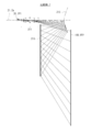
- FIG. 4 shows a cross-sectional configuration of the projection optical system 1 and the image display device according to the first embodiment together with an optical path.
- [Table 1] shows numerical data showing the basic configurations of the projection optical system 1 and the image display device according to the first embodiment.
- the screen 10 has a cylindrical surface shape with the reference axis Za as the rotation axis.
- the prism optical system 30 is arranged between the image generation unit 20 and the refraction optical system 11.
- the surfaces S13 and S14 of the refractive optics system 11 and the reflection surface (S15) of the reflection optical system 12 have an aspherical shape.
- [Table 2] shows the values of the aspherical coefficient indicating those aspherical shapes.
- the screen 10 is arranged at an eccentric and tilted position with respect to the refraction optical system 11 and the reflection optical system 12.
- Table 3 shows detailed shape data of the screen 10 in the image display device according to the first embodiment, and data on eccentricity and tilt.
- the optical axis of the screen 10 (the axis orthogonal to the screen surface (projection surface)) is defined as the Z axis.
- the X-axis is the horizontal axis of the screen surface
- the Y-axis is the vertical axis of the screen surface.
- the X-axis is an axis orthogonal to the paper surface of FIG.
- the Y-axis is an axis parallel to the paper surface of FIG.
- RDY indicates the radius of curvature in the Y-axis direction
- RDX indicates the radius of curvature in the X-axis direction.
- XDE, YDE, ZDE indicates eccentricity data (eccentricity amount).
- ADE, BDE, CDE indicates Euler angle (tilt angle) data.
- ADE means the amount of rotation of the screen surface from the Z-axis direction to the Y-axis direction about the X-axis.
- BDE means the amount of rotation from the X-axis direction to the Z-axis direction about the Y-axis.
- CDE means the amount of rotation from the X-axis direction to the Y-axis direction about the Z-axis. The same applies to the table showing the detailed shape data of the screen 10 and the data related to eccentricity and tilt in other examples described later.
- FIG. 5 shows a cross-sectional configuration of the projection optical system 2 and the image display device according to the second embodiment together with an optical path.
- [Table 4] shows numerical data showing the basic configurations of the projection optical system 2 and the image display device according to the second embodiment.
- the screen 10 has a cylindrical surface shape with the reference axis Za as the rotation axis.
- the prism optical system 30 is arranged between the image generation unit 20 and the refraction optical system 11.
- the surfaces S14 and S15 of the refractive optics system 11 and the reflection surface (S16) of the reflection optical system 12 have an aspherical shape.
- [Table 5] shows the values of the aspherical coefficient indicating those aspherical shapes.
- the screen 10 is arranged at an eccentric and tilted position with respect to the refraction optical system 11 and the reflection optical system 12.
- Table 6 shows detailed shape data of the screen 10 in the image display device according to the second embodiment, and data on eccentricity and tilt.
- FIG. 6 shows the cross-sectional configuration of the projection optical system 3 and the image display device according to the third embodiment together with the optical path.
- [Table 7] shows numerical data showing the basic configurations of the projection optical system 3 and the image display device according to the third embodiment.
- the screen 10 has a cylindrical surface shape with the reference axis Za as the rotation axis.
- the surfaces S1, S2, S3, S4, S8, S9 in the refractive optical system 11 and the reflective surface (S11) in the reflective optical system 12 have an aspherical shape.
- [Table 8] shows the values of the aspherical coefficient indicating those aspherical shapes.
- the screen 10 is arranged at an eccentric and tilted position with respect to the refraction optical system 11 and the reflection optical system 12.
- Table 9 shows detailed shape data of the screen 10 in the image display device according to the third embodiment, and data on eccentricity and tilt.
- FIG. 7 shows the cross-sectional configuration of the projection optical system 4 and the image display device according to the fourth embodiment together with the optical path.
- [Table 10] shows numerical data showing the basic configurations of the projection optical system 4 and the image display device according to the fourth embodiment.
- the screen 10 has a flat shape.
- the prism optical system 30 is arranged between the image generation unit 20 and the refraction optical system 11.
- the surfaces S13 and S14 of the refractive optics system 11 and the reflection surface (S15) of the reflection optical system 12 have an aspherical shape.
- [Table 11] shows the values of the aspherical coefficient indicating those aspherical shapes.
- Table 12 shows detailed shape data of the screen 10 in the image display device according to the fourth embodiment and data on eccentricity and tilt.
- the screen 10 is not eccentric and tilted with respect to the refraction optical system 11 and the reflection optical system 12.
- FIG. 8 shows the cross-sectional configuration of the projection optical system 5 and the image display device according to the fifth embodiment together with the optical path.
- [Table 13] shows numerical data showing the basic configurations of the projection optical system 5 and the image display device according to the fifth embodiment.
- the screen 10 has a spherical shape.
- the prism optical system 30 is arranged between the image generation unit 20 and the refraction optical system 11.
- the surfaces S13 and S14 of the refractive optics system 11 and the reflection surface (S15) of the reflection optical system 12 have an aspherical shape.
- [Table 14] shows the values of the aspherical coefficient indicating those aspherical shapes.
- [Table 15] shows detailed shape data of the screen 10 in the image display device according to the fifth embodiment and data on eccentricity and tilt.
- the screen 10 is not eccentric and tilted with respect to the refraction optical system 11 and the reflection optical system 12.
- [Comparison with other numerical data of each example and comparative example] [Table 16] shows a summary of the values related to each of the above conditional expressions for each embodiment. As can be seen from [Table 16], the projection optical system according to each embodiment satisfies each conditional expression. Further, [Table 17] shows a summary of the values related to each of the above conditional expressions for Comparative Examples 1 and 2.
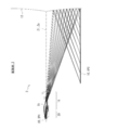
- FIG. 9 shows the configurations of the projection optical system and the image display device according to Comparative Example 1 together with the optical path.
- the projection optical system and the image display device according to Comparative Example 1 correspond to the examples of FIGS. 21 and 22 in Patent Document 1 (Japanese Unexamined Patent Publication No. 2002-207168).
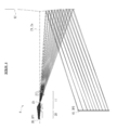
- FIG. 10 shows the configurations of the projection optical system and the image display device according to Comparative Example 2 together with the optical path.
- the projection optical system and the image display device according to Comparative Example 2 correspond to the examples of FIGS. 28 and 29 in Patent Document 1 (Japanese Unexamined Patent Publication No. 2002-207168).
- the configuration of the image display device according to Comparative Examples 1 and 2 corresponds to the configuration of the image display device according to the comparative example shown in FIG.
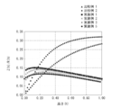
- FIG. 11 shows, for each example and each comparative example, a derivative Z'(h) obtained by first-order differentiation of a function Z (h) indicating a standardized ray height h and a sag amount Z of the aspherical shape of the reflecting surface. ) Is shown in a graph.
- the characteristics shown in FIG. 11 are characteristics related to the above conditional expression (1).
- FIG. 12 shows, for each example and each comparative example, a derivative Z'(h) obtained by first-order differentiation of a function Z (h) indicating a standardized ray height h and a sag amount Z of the aspherical shape of the reflecting surface. ) Is graphed and shown in relation to the amount of change ⁇ Z'(h).
- the characteristic shown in FIG. 11 is a characteristic related to the conditional expression (2).
- FIG. 13 shows the aspherical shape sag amount (Z (h) / R (h) of the reflecting surface with respect to the standardized ray height h and the actual ray height R (h) for each example and each comparative example. )) Is shown in a graph.
- the characteristic shown in FIG. 13 is a characteristic related to the conditional expression (3).
- the present technology may have the following configuration.
- the shape of the reflective surface of the reflective optical system is optimized so that the emission angle of the light rays emitted from the reflective surface is substantially constant, so that the image quality is improved. It becomes possible to make it.
- a folding optics system that has a positive refractive power as a whole and is arranged with reference to a reference axis at a position where image light from the primary image plane is incident.
- the shape of the reflecting surface has a reflecting surface that reflects the image light emitted from the refraction optical system toward a projection surface forming a secondary image plane, and within a light effective range in which the image light is incident.
- the shape of the reflective surface in the cross section including the reference axis is the reference axis, which has a rotationally symmetric aspherical shape having a sag amount in the direction opposite to the refraction optical system with the reference axis as the rotation axis.
- a projection optical system including a reflective optical system configured to have a shape that is inclined so as to approach a right angle in the region farthest from the reference axis as compared with the region closest to the reference axis.
- Z'(1.0) First-order differential value of the function Z (h) when the normalized ray height h is 1.0
- Z'(0.2) The normalized ray height Let it be the first-order differential value of the function Z (h) when h is 0.2. [4] The height of light rays from the reference axis whose maximum value is standardized to 1.0 is h, the function representing the sag amount of the aspherical shape of the reflecting surface is Z (h), and the function Z (h) is the standard.
- the projection optical system is A refractive optics system having a positive refractive power as a whole and arranged with reference to a reference axis at a position where the image light from the primary image plane is incident.
- the shape of the reflecting surface has a reflecting surface that reflects the image light emitted from the refractory optical system toward a projection surface forming a secondary image plane, and within a light effective range in which the image light is incident.
- the shape of the reflective surface in the cross section including the reference axis is the reference axis, which has a rotationally symmetric aspherical shape having a sag amount in the direction opposite to the refractive optical system with the reference axis as the rotation axis.
- An image display device including a reflection optical system configured to have a shape that is inclined so as to approach a right angle in a region farthest from the reference axis as compared with a region closest to the reference axis.
Landscapes
- Physics & Mathematics (AREA)
- General Physics & Mathematics (AREA)
- Optics & Photonics (AREA)
- Lenses (AREA)
- Projection Apparatus (AREA)
Priority Applications (1)
| Application Number | Priority Date | Filing Date | Title |
|---|---|---|---|
| JP2021552355A JP7722187B2 (ja) | 2019-10-15 | 2020-10-08 | 投射光学系、および画像表示装置 |
Applications Claiming Priority (2)
| Application Number | Priority Date | Filing Date | Title |
|---|---|---|---|
| JP2019188725 | 2019-10-15 | ||
| JP2019-188725 | 2019-10-15 |
Publications (1)
| Publication Number | Publication Date |
|---|---|
| WO2021075341A1 true WO2021075341A1 (ja) | 2021-04-22 |
Family
ID=75537968
Family Applications (1)
| Application Number | Title | Priority Date | Filing Date |
|---|---|---|---|
| PCT/JP2020/038092 Ceased WO2021075341A1 (ja) | 2019-10-15 | 2020-10-08 | 投射光学系、および画像表示装置 |
Country Status (2)
| Country | Link |
|---|---|
| JP (1) | JP7722187B2 (https=) |
| WO (1) | WO2021075341A1 (https=) |
Citations (6)
| Publication number | Priority date | Publication date | Assignee | Title |
|---|---|---|---|---|
| JP2009271372A (ja) * | 2008-05-08 | 2009-11-19 | Panasonic Corp | 投写光学系、投写システム及び投写型表示装置 |
| US20110002051A1 (en) * | 2009-07-03 | 2011-01-06 | Ya-Ling Hsu | Fixed focus lens and imaging system |
| JP2012008353A (ja) * | 2010-06-25 | 2012-01-12 | National Institute Of Advanced Industrial & Technology | 光制御素子 |
| JP2015060090A (ja) * | 2013-09-19 | 2015-03-30 | 富士フイルム株式会社 | 投写光学系および投写型表示装置 |
| JP2017010023A (ja) * | 2015-06-19 | 2017-01-12 | キヤノン株式会社 | 結像光学系、光学機器および画像投射装置 |
| US20180210181A1 (en) * | 2017-01-26 | 2018-07-26 | Heekyung KIM | Ultra-short throw projector |
Family Cites Families (1)
| Publication number | Priority date | Publication date | Assignee | Title |
|---|---|---|---|---|
| JP2012008358A (ja) * | 2010-06-25 | 2012-01-12 | Olympus Corp | 投影光学装置 |
-
2020
- 2020-10-08 WO PCT/JP2020/038092 patent/WO2021075341A1/ja not_active Ceased
- 2020-10-08 JP JP2021552355A patent/JP7722187B2/ja active Active
Patent Citations (6)
| Publication number | Priority date | Publication date | Assignee | Title |
|---|---|---|---|---|
| JP2009271372A (ja) * | 2008-05-08 | 2009-11-19 | Panasonic Corp | 投写光学系、投写システム及び投写型表示装置 |
| US20110002051A1 (en) * | 2009-07-03 | 2011-01-06 | Ya-Ling Hsu | Fixed focus lens and imaging system |
| JP2012008353A (ja) * | 2010-06-25 | 2012-01-12 | National Institute Of Advanced Industrial & Technology | 光制御素子 |
| JP2015060090A (ja) * | 2013-09-19 | 2015-03-30 | 富士フイルム株式会社 | 投写光学系および投写型表示装置 |
| JP2017010023A (ja) * | 2015-06-19 | 2017-01-12 | キヤノン株式会社 | 結像光学系、光学機器および画像投射装置 |
| US20180210181A1 (en) * | 2017-01-26 | 2018-07-26 | Heekyung KIM | Ultra-short throw projector |
Also Published As
| Publication number | Publication date |
|---|---|
| JPWO2021075341A1 (https=) | 2021-04-22 |
| JP7722187B2 (ja) | 2025-08-13 |
Similar Documents
| Publication | Publication Date | Title |
|---|---|---|
| JP6368988B2 (ja) | 投射光学系および画像表示装置 | |
| JP4329863B2 (ja) | 投影光学系及び画像投影装置 | |
| JP6387967B2 (ja) | ヘッドマウントディスプレイ用光学系、およびヘッドマウントディスプレイ | |
| JP2023155289A (ja) | 光学系、画像投写装置および撮像装置 | |
| US10890840B2 (en) | Projection optical system unit, projection optical system, and projection optical apparatus | |
| US8425044B2 (en) | Projection optical system | |
| JP7585582B2 (ja) | 光学レンズ | |
| US8113667B2 (en) | Projection optical system | |
| JP6811412B2 (ja) | 投写光学系、画像投写装置および画像投写システム | |
| JP4419243B2 (ja) | 斜め投影光学系 | |
| JP2005301074A (ja) | 投影光学系 | |
| JP6393906B2 (ja) | 投写光学系および画像投写装置 | |
| JP2008242025A (ja) | 投影光学系 | |
| JP2022080873A (ja) | 結像システム及び投影装置 | |
| JP6598050B2 (ja) | 投射装置および投射システム | |
| JP6497573B2 (ja) | 投射装置および投射システム | |
| JP2019045847A (ja) | ヘッドマウント式表示装置及び像形成レンズユニット | |
| WO2019065259A1 (ja) | 画像投写装置 | |
| WO2021075341A1 (ja) | 投射光学系、および画像表示装置 | |
| JP2015096887A (ja) | 投射光学系および画像表示装置 | |
| JP5257904B2 (ja) | 投影光学系および投影装置 | |
| US7748855B2 (en) | Image projection apparatus | |
| JP5987459B2 (ja) | 映像投写装置用光学系および映像投写装置 | |
| CN114518643A (zh) | 成像系统及投影装置 | |
| JP6341367B2 (ja) | 投射装置、および投射システム |
Legal Events
| Date | Code | Title | Description |
|---|---|---|---|
| 121 | Ep: the epo has been informed by wipo that ep was designated in this application |
Ref document number: 20877316 Country of ref document: EP Kind code of ref document: A1 |
|
| ENP | Entry into the national phase |
Ref document number: 2021552355 Country of ref document: JP Kind code of ref document: A |
|
| NENP | Non-entry into the national phase |
Ref country code: DE |
|
| 122 | Ep: pct application non-entry in european phase |
Ref document number: 20877316 Country of ref document: EP Kind code of ref document: A1 |