WO2021075285A1 - Connecteur - Google Patents
Connecteur Download PDFInfo
- Publication number
- WO2021075285A1 WO2021075285A1 PCT/JP2020/037675 JP2020037675W WO2021075285A1 WO 2021075285 A1 WO2021075285 A1 WO 2021075285A1 JP 2020037675 W JP2020037675 W JP 2020037675W WO 2021075285 A1 WO2021075285 A1 WO 2021075285A1
- Authority
- WO
- WIPO (PCT)
- Prior art keywords
- terminal
- terminals
- right direction
- width
- distance
- Prior art date
Links
Images


Classifications
-
- H—ELECTRICITY
- H01—ELECTRIC ELEMENTS
- H01R—ELECTRICALLY-CONDUCTIVE CONNECTIONS; STRUCTURAL ASSOCIATIONS OF A PLURALITY OF MUTUALLY-INSULATED ELECTRICAL CONNECTING ELEMENTS; COUPLING DEVICES; CURRENT COLLECTORS
- H01R12/00—Structural associations of a plurality of mutually-insulated electrical connecting elements, specially adapted for printed circuits, e.g. printed circuit boards [PCB], flat or ribbon cables, or like generally planar structures, e.g. terminal strips, terminal blocks; Coupling devices specially adapted for printed circuits, flat or ribbon cables, or like generally planar structures; Terminals specially adapted for contact with, or insertion into, printed circuits, flat or ribbon cables, or like generally planar structures
- H01R12/70—Coupling devices
- H01R12/71—Coupling devices for rigid printing circuits or like structures
- H01R12/72—Coupling devices for rigid printing circuits or like structures coupling with the edge of the rigid printed circuits or like structures
- H01R12/73—Coupling devices for rigid printing circuits or like structures coupling with the edge of the rigid printed circuits or like structures connecting to other rigid printed circuits or like structures
-
- H—ELECTRICITY
- H01—ELECTRIC ELEMENTS
- H01R—ELECTRICALLY-CONDUCTIVE CONNECTIONS; STRUCTURAL ASSOCIATIONS OF A PLURALITY OF MUTUALLY-INSULATED ELECTRICAL CONNECTING ELEMENTS; COUPLING DEVICES; CURRENT COLLECTORS
- H01R13/00—Details of coupling devices of the kinds covered by groups H01R12/70 or H01R24/00 - H01R33/00
- H01R13/02—Contact members
-
- H—ELECTRICITY
- H01—ELECTRIC ELEMENTS
- H01R—ELECTRICALLY-CONDUCTIVE CONNECTIONS; STRUCTURAL ASSOCIATIONS OF A PLURALITY OF MUTUALLY-INSULATED ELECTRICAL CONNECTING ELEMENTS; COUPLING DEVICES; CURRENT COLLECTORS
- H01R12/00—Structural associations of a plurality of mutually-insulated electrical connecting elements, specially adapted for printed circuits, e.g. printed circuit boards [PCB], flat or ribbon cables, or like generally planar structures, e.g. terminal strips, terminal blocks; Coupling devices specially adapted for printed circuits, flat or ribbon cables, or like generally planar structures; Terminals specially adapted for contact with, or insertion into, printed circuits, flat or ribbon cables, or like generally planar structures
- H01R12/70—Coupling devices
- H01R12/71—Coupling devices for rigid printing circuits or like structures
- H01R12/712—Coupling devices for rigid printing circuits or like structures co-operating with the surface of the printed circuit or with a coupling device exclusively provided on the surface of the printed circuit
- H01R12/716—Coupling device provided on the PCB
-
- H—ELECTRICITY
- H01—ELECTRIC ELEMENTS
- H01R—ELECTRICALLY-CONDUCTIVE CONNECTIONS; STRUCTURAL ASSOCIATIONS OF A PLURALITY OF MUTUALLY-INSULATED ELECTRICAL CONNECTING ELEMENTS; COUPLING DEVICES; CURRENT COLLECTORS
- H01R13/00—Details of coupling devices of the kinds covered by groups H01R12/70 or H01R24/00 - H01R33/00
- H01R13/02—Contact members
- H01R13/22—Contacts for co-operating by abutting
- H01R13/24—Contacts for co-operating by abutting resilient; resiliently-mounted
- H01R13/2407—Contacts for co-operating by abutting resilient; resiliently-mounted characterized by the resilient means
-
- H—ELECTRICITY
- H01—ELECTRIC ELEMENTS
- H01R—ELECTRICALLY-CONDUCTIVE CONNECTIONS; STRUCTURAL ASSOCIATIONS OF A PLURALITY OF MUTUALLY-INSULATED ELECTRICAL CONNECTING ELEMENTS; COUPLING DEVICES; CURRENT COLLECTORS
- H01R13/00—Details of coupling devices of the kinds covered by groups H01R12/70 or H01R24/00 - H01R33/00
- H01R13/40—Securing contact members in or to a base or case; Insulating of contact members
- H01R13/405—Securing in non-demountable manner, e.g. moulding, riveting
-
- H—ELECTRICITY
- H01—ELECTRIC ELEMENTS
- H01R—ELECTRICALLY-CONDUCTIVE CONNECTIONS; STRUCTURAL ASSOCIATIONS OF A PLURALITY OF MUTUALLY-INSULATED ELECTRICAL CONNECTING ELEMENTS; COUPLING DEVICES; CURRENT COLLECTORS
- H01R13/00—Details of coupling devices of the kinds covered by groups H01R12/70 or H01R24/00 - H01R33/00
- H01R13/62—Means for facilitating engagement or disengagement of coupling parts or for holding them in engagement
- H01R13/629—Additional means for facilitating engagement or disengagement of coupling parts, e.g. aligning or guiding means, levers, gas pressure electrical locking indicators, manufacturing tolerances
-
- H—ELECTRICITY
- H01—ELECTRIC ELEMENTS
- H01R—ELECTRICALLY-CONDUCTIVE CONNECTIONS; STRUCTURAL ASSOCIATIONS OF A PLURALITY OF MUTUALLY-INSULATED ELECTRICAL CONNECTING ELEMENTS; COUPLING DEVICES; CURRENT COLLECTORS
- H01R13/00—Details of coupling devices of the kinds covered by groups H01R12/70 or H01R24/00 - H01R33/00
- H01R13/64—Means for preventing incorrect coupling
- H01R13/642—Means for preventing incorrect coupling by position or shape of contact members
-
- H—ELECTRICITY
- H01—ELECTRIC ELEMENTS
- H01R—ELECTRICALLY-CONDUCTIVE CONNECTIONS; STRUCTURAL ASSOCIATIONS OF A PLURALITY OF MUTUALLY-INSULATED ELECTRICAL CONNECTING ELEMENTS; COUPLING DEVICES; CURRENT COLLECTORS
- H01R13/00—Details of coupling devices of the kinds covered by groups H01R12/70 or H01R24/00 - H01R33/00
- H01R13/648—Protective earth or shield arrangements on coupling devices, e.g. anti-static shielding
- H01R13/658—High frequency shielding arrangements, e.g. against EMI [Electro-Magnetic Interference] or EMP [Electro-Magnetic Pulse]
- H01R13/6591—Specific features or arrangements of connection of shield to conductive members
- H01R13/6594—Specific features or arrangements of connection of shield to conductive members the shield being mounted on a PCB and connected to conductive members
Definitions
- the present invention relates to a connector having a plurality of terminals having different sizes.
- the connector described in Patent Document 1 includes a plurality of first terminals arranged in a first row extending in the left-right direction and a plurality of second terminals arranged in a second row extending in the left-right direction.
- the plurality of first terminals include a left end first terminal located at the left end of the plurality of first terminals and a right end first terminal located at the right end of the plurality of first terminals.
- the leftmost first terminal and the rightmost first terminal are larger than the first terminals (intermediate first terminals) other than the leftmost first terminal and the rightmost first terminal.
- the plurality of second terminals include a left end second terminal located at the left end of the plurality of second terminals and a right end second terminal located at the right end of the plurality of second terminals.
- the leftmost second terminal and the rightmost second terminal are larger than the second terminal (intermediate second terminal) other than the leftmost second terminal and the rightmost second terminal.
- the intermediate first terminal which is a small terminal
- the intermediate second terminal which is a small terminal
- the arrangement of the connector terminals described in Patent Document 1 is arranged by, for example, a large terminal such as the leftmost first terminal and the rightmost first terminal and a small terminal such as the intermediate first terminal and the intermediate second terminal. You may want to change it so that it is aligned in the direction.
- an object of the present invention is to provide a connector capable of increasing the degree of freedom in layout of a plurality of terminals and suppressing an increase in the size of the connector.
- the connector according to the first invention is With multiple terminals Insulating member holding the plurality of terminals and Is equipped with
- the plurality of terminals include a first terminal and a second terminal arranged in a first row extending in the left-right direction.
- the plurality of terminals include a third terminal and a fourth terminal arranged in a second row extending in the left-right direction.
- the first row is located before or after the second row.
- the second terminal is arranged to the right of the first terminal and is adjacent to the first terminal.
- the third terminal is arranged to the right of the fourth terminal and is adjacent to the fourth terminal.
- the first terminal overlaps with the fourth terminal when viewed in the front-rear direction.
- the second terminal overlaps with the third terminal when viewed in the front-rear direction.
- the first width of the first terminal in the left-right direction is larger than the second width of the second terminal in the left-right direction.
- the third width in the left-right direction of the third terminal is larger than the fourth width in the left-right direction of the fourth terminal.
- Half of the value obtained by subtracting the fourth width from the first width is defined as the first distance.
- Half of the value obtained by subtracting the second width from the third width is defined as the second distance.
- the first terminal, the second terminal, the third terminal, and the fourth terminal are arranged so as to satisfy the conditions (A) and (B).
- the left end of the first terminal is located to the left of the left end of the fourth terminal, and the distance between the left end of the first terminal and the left end of the fourth terminal in the left-right direction is the first.
- the connector according to the second invention is with multiple terminals Insulating member holding the plurality of terminals and Is equipped with
- the plurality of terminals include a first terminal and a second terminal arranged in a first row extending in the left-right direction.
- the plurality of terminals include a third terminal and a fourth terminal arranged in a second row extending in the left-right direction.
- the first row is located before or after the second row.
- the second terminal is arranged to the right of the first terminal and is adjacent to the first terminal.
- the third terminal is arranged to the right of the fourth terminal and is adjacent to the fourth terminal.
- the first terminal overlaps with the fourth terminal when viewed in the front-rear direction.
- the second terminal overlaps with the third terminal when viewed in the front-rear direction.
- the first width of the first terminal in the left-right direction is larger than the second width of the second terminal in the left-right direction.
- the third width in the left-right direction of the third terminal is larger than the fourth width in the left-right direction of the fourth terminal.
- Half of the value obtained by subtracting the fourth width from the first width is defined as the first distance.
- Half of the value obtained by subtracting the second width from the third width is defined as the second distance.
- the first terminal, the second terminal, the third terminal, and the fourth terminal are arranged so as to satisfy the conditions (C) and (D).
- C) (c1) The left end of the fourth terminal is located to the left of the left end of the first terminal, and the distance between the left end of the first terminal and the left end of the fourth terminal in the left-right direction is the second.
- the connector according to the third invention is with multiple terminals Insulating member holding the plurality of terminals and Is equipped with
- the plurality of terminals include a first terminal, a second terminal, and a plurality of fifth terminals arranged in a first row extending in the left-right direction.
- the plurality of terminals include a third terminal, a fourth terminal, and a plurality of sixth terminals arranged in a second row extending in the left-right direction.
- the first row is located before or after the second row.
- the second terminal is arranged to the right of the first terminal.
- the plurality of fifth terminals are arranged to the right of the first terminal and to the left of the second terminal.
- the third terminal is arranged to the right of the fourth terminal.
- the plurality of sixth terminals are arranged to the right of the fourth terminal and to the left of the third terminal.
- the first terminal overlaps with the fourth terminal when viewed in the front-rear direction.
- the second terminal overlaps with the third terminal when viewed in the front-rear direction.
- the first width of the first terminal in the left-right direction is larger than the second width of the second terminal in the left-right direction.
- the third width in the left-right direction of the third terminal is larger than the fourth width in the left-right direction of the fourth terminal.
- the fifth width of the plurality of fifth terminals in the left-right direction is uniform.
- the sixth width of the plurality of sixth terminals in the left-right direction is uniform. Half of the value obtained by subtracting the fourth width from the first width is defined as the first distance.
- Half of the value obtained by subtracting the second width from the third width is defined as the second distance.
- the first terminal, the second terminal, the third terminal, and the fourth terminal are arranged so as to satisfy the conditions (A) and (B).
- the connector according to the fourth invention is with multiple terminals Insulating member holding the plurality of terminals and Is equipped with
- the plurality of terminals include a first terminal, a second terminal, and a plurality of fifth terminals arranged in a first row extending in the left-right direction.
- the plurality of terminals include a third terminal, a fourth terminal, and a plurality of sixth terminals arranged in a second row extending in the left-right direction.
- the first row is located before or after the second row.
- the second terminal is arranged to the right of the first terminal.
- the plurality of fifth terminals are arranged to the right of the first terminal and to the left of the second terminal.
- the third terminal is arranged to the right of the fourth terminal.
- the plurality of sixth terminals are arranged to the right of the fourth terminal and to the left of the third terminal.
- the first terminal overlaps with the fourth terminal when viewed in the front-rear direction.
- the second terminal overlaps with the third terminal when viewed in the front-rear direction.
- the first width of the first terminal in the left-right direction is larger than the second width of the second terminal in the left-right direction.
- the third width in the left-right direction of the third terminal is larger than the fourth width in the left-right direction of the fourth terminal.
- the fifth width of the plurality of fifth terminals in the left-right direction is uniform.
- the sixth width of the plurality of sixth terminals in the left-right direction is uniform. Half of the value obtained by subtracting the fourth width from the first width is defined as the first distance.
- Half of the value obtained by subtracting the second width from the third width is defined as the second distance.
- the first terminal, the second terminal, the third terminal, and the fourth terminal are arranged so as to satisfy the conditions (C) and (D).
- the left end of the fourth terminal is located to the left of the left end of the first terminal, and the distance between the left end of the first terminal and the left end of the fourth terminal in the left-right direction is the second. It is shorter than the distance, or (c2) the left end of the first terminal coincides with the left end of the fourth terminal in the left-right direction.
- the right end of the third terminal is located to the left of the right end of the second terminal, and the distance between the right end of the second terminal and the right end of the third terminal in the left-right direction is the first. It is shorter than the distance, or (d2) the right end of the second terminal coincides with the right end of the third terminal in the left-right direction.
- the degree of freedom in the layout of a plurality of terminals can be increased, and the size of the connector can be suppressed.
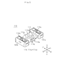
- FIG. 1 is an external perspective view of the first connector 10.
- FIG. 2 is an exploded perspective view of the first connector 10.
- FIG. 3 is a top view of the first connector 10.
- FIG. 4 is a top view of the plurality of terminals 14 of the connectors 210 and 310 according to the comparative example, and a top view of the plurality of terminals 14 of the first connectors 10, 10a and 10b.
- FIG. 5 is an external perspective view of the second connector 110.
- FIG. 6 is an exploded perspective view of the second connector 110.
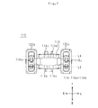
- FIG. 7 is a bottom view of the second connector 110.
- FIG. 1 is an external perspective view of the first connector 10.
- FIG. 2 is an exploded perspective view of the first connector 10.
- FIG. 3 is a top view of the first connector 10.
- the vertical direction, the horizontal direction, and the front-back direction are defined.
- the vertical direction, the horizontal direction, and the front-back direction are the directions defined for the sake of explanation. Therefore, the vertical direction, the horizontal direction, and the front-rear direction of the first connector 10 in actual use do not have to coincide with the vertical direction, the left-right direction, and the front-rear direction of FIGS. 1 to 3.
- the shafts and members extending in the front-rear direction do not necessarily indicate only the shafts and members that are parallel to the front-rear direction.
- a shaft or member extending in the front-rear direction is a shaft or member inclined in a range of ⁇ 45 ° with respect to the front-rear direction.
- a shaft or member extending in the vertical direction is a shaft or member inclined in a range of ⁇ 45 ° with respect to the vertical direction.
- a shaft or member extending in the left-right direction is a shaft or member inclined in a range of ⁇ 45 ° with respect to the left-right direction.
- the first member and the second member arranged in the front-rear direction indicate the following states.
- both the first member and the second member are arranged on an arbitrary straight line indicating the front-rear direction.
- the first member and the second member arranged in the front-rear direction when viewed in the vertical direction indicate the following states.
- both the first member and the second member are arranged on an arbitrary straight line indicating the front-rear direction.
- first member and the second member when the first member and the second member are viewed from a left-right direction different from the vertical direction, one of the first member and the second member may not be arranged on an arbitrary straight line indicating the front-rear direction. ..
- the first member and the second member may be in contact with each other.
- the first member and the second member may be separated from each other.
- a third member may be present between the first member and the second member. This definition also applies to directions other than the front-back direction.
- the first member to the third member are a part of the connector.
- the fact that the first member is arranged in front of the second member means the following state. At least a part of the first member is arranged in a region through which the second member translates in the forward direction. Therefore, the first member may be contained in the region through which the second member passes when it is translated in the forward direction, or protrudes from the region through which the second member is translated when it is translated in the forward direction. May be good. In this case, the first member and the second member are arranged in the front-rear direction. This definition also applies to directions other than the front-back direction.
- the first member when the first member is arranged in front of the second member when viewed in the left-right direction, it means the following state.
- the first member and the second member When viewed in the left-right direction, the first member and the second member are lined up in the front-rear direction, and when viewed in the left-right direction, the portion of the first member facing the second member is the second member. Placed in front.
- the first member and the second member do not have to be arranged in the front-rear direction in three dimensions. This definition applies to directions other than the front-back direction.
- the fact that the first member is arranged before the second member means the following state.
- the first member is arranged in front of a plane that passes through the front end of the second member and is orthogonal to the front-rear direction.
- the first member and the second member may or may not be arranged in the front-rear direction.
- This definition also applies to directions other than the front-back direction.
- each part of the first member is defined as follows.
- the front part of the first member means the front half of the first member.
- the rear part of the first member means the rear half of the first member.
- the left portion of the first member means the left half of the first member.
- the right portion of the first member means the right half of the first member.
- the upper part of the first member means the upper half of the first member.
- the lower part of the first member means the lower half of the first member.
- the front end of the first member means the end in the front direction of the first member.
- the rear end of the first member means the rear end of the first member.
- the left end of the first member means the left end of the first member.
- the right end of the first member means the right end of the first member.
- the upper end of the first member means the upper end of the first member.
- the lower end of the first member means the lower end of the first member.
- the front end portion of the first member means the front end portion of the first member and its vicinity.
- the rear end portion of the first member means the rear end portion of the first member and its vicinity.
- the left end portion of the first member means the left end portion of the first member and its vicinity.
- the right end portion of the first member means the right end portion of the first member and its vicinity.
- the upper end portion of the first member means the upper end portion of the first member and its vicinity.
- the lower end of the first member means the lower end of the first member and its vicinity.
- the first connector 10 is connected to the second connector 110, which will be described later.
- the first connector 10 is mounted on a circuit board such as a flexible board.
- the first connector 10 includes an insulating member 12, a plurality of terminals 14 (a plurality of terminals), high frequency terminals 16a and 16b, contact terminals 18a to 18f, and an external terminal 20.
- the insulating member 12 is a block having a rectangular shape when viewed downward.
- the insulating member 12 is made of, for example, an insulating resin such as a liquid crystal polymer.
- the insulating member 12 holds a plurality of terminals 14, high frequency terminals 16a and 16b, contact terminals 18a to 18f, and an external terminal 20.
- the insulating member 12 is integrated with the plurality of terminals 14, the high frequency terminals 16a and 16b, the contact terminals 18a to 18f, and the external terminal 20 by, for example, insert molding. Therefore, a plurality of terminals 14, high frequency terminals 16a and 16b, contact terminals 18a to 18f, and a part of the external terminals 20 are embedded in the insulating member 12.
- the external terminal 20 is a conductor connected to the ground potential.
- the external terminal 20 has a rectangular ring shape when viewed downward.
- the long side of the external terminal 20 extends in the left-right direction.
- the short side of the external terminal 20 extends in the front-rear direction.
- the external terminal 20 is manufactured by bending a single metal plate.
- the external terminal 20 is made of a copper-based material such as phosphor bronze.
- the external terminal 20 Since the external terminal 20 has a rectangular ring shape when viewed downward, it covers the vicinity of the front side, the vicinity of the rear side, the vicinity of the left side, and the vicinity of the right side of the upper surface of the insulating member 12. However, since the external terminal 20 has a rectangular ring shape when viewed downward, the central portion of the insulating member 12 is exposed from the external terminal 20 when viewed downward. There is. The external terminal 20 covers a part of the front surface, a part of the rear surface, a part of the left surface, and a part of the right surface of the insulating member 12.
- the plurality of terminals 14 include a first terminal 14a, a second terminal 14b, a third terminal 14c, and a fourth terminal 14d.
- the first terminal 14a, the second terminal 14b, the third terminal 14c, and the fourth terminal 14d are arranged near the center of the insulating member 12 from the outer edge of the insulating member 12 when viewed downward.
- the first terminal 14a and the second terminal 14b are arranged in the first row L1 extending in the left-right direction. That is, the first terminal 14a and the second terminal 14b are arranged in the left-right direction.
- the second terminal 14b is arranged to the right of the first terminal 14a. Further, the second terminal 14b is adjacent to the first terminal 14a. Therefore, no other terminal is arranged between the first terminal 14a and the second terminal 14b.
- the third terminal 14c and the fourth terminal 14d are arranged in the second row L2 extending in the left-right direction. That is, the third terminal 14c and the fourth terminal 14d are arranged in the left-right direction.
- the third terminal 14c is arranged to the right of the fourth terminal 14d. Further, the third terminal 14c is adjacent to the fourth terminal 14d. Therefore, no other terminal is arranged between the fourth terminal 14d and the third terminal 14c.
- the first row L1 is located after the second row L2.
- the first terminal 14a overlaps with the fourth terminal 14d when viewed in the front-rear direction.
- the first terminal 14a is arranged after the fourth terminal 14d.
- the fourth terminal 14d does not protrude in the left-right direction from the first terminal 14a when viewed in the front-rear direction.
- the second terminal 14b overlaps with the third terminal 14c when viewed in the front-rear direction.
- the second terminal 14b is arranged after the third terminal 14c.
- the second terminal 14b does not protrude in the left-right direction from the third terminal 14c when viewed in the front-rear direction.
- the first width W1 in the left-right direction of the first terminal 14a is larger than the second width W2 in the left-right direction of the second terminal 14b. Therefore, the conductor loss of the first terminal 14a is smaller than the conductor loss of the second terminal 14b.
- the third width W3 in the left-right direction of the third terminal 14c is larger than the fourth width W4 in the left-right direction of the fourth terminal 14d. Therefore, the conductor loss of the third terminal 14c is smaller than the conductor loss of the fourth terminal 14d.
- the first width W1 and the third width W3 are equal.
- the second width W2 and the fourth width W4 are equal.
- the first width W1 and the fourth width W4 are not equal.
- the second width W2 and the third width W3 are not equal.
- the first width W1 is the maximum value of the width of the first terminal 14a in the left-right direction.
- the second width W2 is the maximum value of the width of the second terminal 14b in the left-right direction.
- the third width W3 is the maximum value of the width of the third terminal 14c in the left-right direction.
- the fourth width W4 is the maximum value of the width of the fourth terminal 14d in the left-right direction. Further, the distance between the right end of the first terminal 14a and the left end of the second terminal 14b is equal to the distance between the left end of the third terminal 14c and the right end of the fourth terminal 14d.
- the first terminal 14a and the third terminal 14c are power supply terminals. Therefore, the first terminal 14a and the third terminal 14c are terminals connected to the power supply potential.
- the second terminal 14b and the fourth terminal 14d are terminals for digital signals. Therefore, the second terminal 14b and the fourth terminal 14d are terminals to which a digital signal (that is, a high frequency signal) is applied.
- the first terminal 14a, the second terminal 14b, the third terminal 14c, and the fourth terminal 14d have the same structure except that the widths in the left-right direction are different.
- the structures of the first terminal 14a, the second terminal 14b, the third terminal 14c, and the fourth terminal 14d will be described by taking the first terminal 14a as an example.
- the first terminal 14a includes a U-shaped portion 140a, a drawer portion 140b, and a connecting portion 140c.
- the U-shaped portion 140a has a U-shaped shape when viewed in the left-right direction. Therefore, the U-shaped portion 140a has a shape recessed downward.
- the inner surface of the U-shaped portion 140a is exposed from the insulating member 12 when viewed downward.
- the drawer portion 140b is located behind the bottom portion of the U-shaped portion 140a.
- the drawer portion 140b extends linearly in the front-rear direction.
- the rear end of the drawer 140b is exposed from the insulating member 12.
- the connecting portion 140c connects the rear end of the U-shaped portion 140a and the front end of the drawing portion 140b.
- Such a first terminal 14a is manufactured by bending a single metal plate.
- the first terminal 14a is made of a copper-based material such as phosphor bronze.
- the high frequency terminal 16a is arranged on the left side of the insulating member 12 when viewed downward.
- the high frequency terminal 16b is arranged on the right side of the insulating member 12 when viewed downward.
- the high frequency terminals 16a and 16b are terminals to which a high frequency signal is applied.
- the high frequency terminals 16a and 16b have the same structure.
- the structure of the high frequency terminals 16a and 16b will be described by taking the high frequency terminal 16a as an example.
- the high frequency terminal 16a includes an inverted U-shaped portion 160a and a drawer portion 160b.
- the inverted U-shaped portion 160a has a U-shape that is upside down when viewed in the left-right direction. Therefore, the inverted U-shaped portion 160a has a shape protruding upward.
- the outer surface of the inverted U-shaped portion 160a is exposed from the insulating member 12 when viewed downward.
- the drawer portion 160b extends linearly in the forward direction from the front end of the inverted U-shaped portion 160a.
- the front end portion of the drawer portion 160b is exposed from the insulating member 12.
- Such a high frequency terminal 16a is manufactured by bending a single metal plate.
- the high frequency terminal 16a is made of a copper-based material such as phosphor bronze.
- the contact terminals 18a to 18c are arranged on the left side of the insulating member 12 when viewed downward.
- the contact terminal 18a is arranged to the left of the high frequency terminal 16a.
- the contact terminal 18b is arranged in front of the high frequency terminal 16a on the right side.
- the contact terminal 18c is arranged on the right rear side of the high frequency terminal 16a.
- the contact terminals 18d to 18f are arranged on the right side of the insulating member 12 when viewed downward.
- the contact terminal 18d is arranged to the right of the high frequency terminal 16b.
- the contact terminal 18e is arranged in front of the left side of the high frequency terminal 16b.
- the contact terminal 18f is arranged behind the high frequency terminal 16b to the left.
- the contact terminals 18a and 18b are terminals connected to the ground potential.
- the contact terminals 18a and 18b are manufactured by bending a single metal plate.
- the contact terminals 18a and 18b are made of a copper-based material
- the first connector 10 configured as described above is mounted on the circuit board. Specifically, a plurality of terminals 14, high-frequency terminals 16a and 16b, contact terminals 18a to 18f, and an external terminal 20 are connected to a land electrode provided on a circuit board by soldering.
- FIG. 4 is a top view of the plurality of terminals 14 of the connectors 210 and 310 according to the comparative example, and a top view of the plurality of terminals 14 of the first connectors 10, 10a and 10b.
- the first connectors 10a and 10b are modified examples of the first connector 10. Note that FIG. 4 is schematic. Therefore, the sizes of the plurality of terminals 14 in FIG. 4 do not match the sizes of the plurality of terminals 14 in FIGS. 1 to 3. Further, the connectors 210 and 310 are not included in the connector according to the present invention.
- first distance D1 half of the value obtained by subtracting the fourth width W4 from the first width W1 is defined as the first distance D1.
- Half of the value obtained by subtracting the second width W2 from the third width W3 is defined as the second distance D2.
- the first terminal 14a, the second terminal 14b, the third terminal 14c, and the fourth terminal 14d satisfy the conditions of (A) and (B), or the conditions of (C) and (D) are satisfied. Arranged to meet.
- the left end of the first terminal 14a is located to the left of the left end of the fourth terminal 14d, and the distance d1 in the left-right direction between the left end of the first terminal 14a and the left end of the fourth terminal 14d is the first.
- the distance is shorter than D1, or (a2) the left end of the first terminal 14a coincides with the left end of the fourth terminal 14d in the left-right direction.
- the right end of the second terminal 14b is located to the left of the right end of the third terminal 14c, and the distance d2 between the right end of the second terminal 14b and the right end of the third terminal 14c in the left-right direction is the second. It is shorter than the distance D2, or (b2) the right end of the second terminal 14b coincides with the right end of the third terminal 14c in the left-right direction.
- the left end of the fourth terminal 14d is located to the left of the left end of the first terminal 14a, and the distance d1 between the left end of the first terminal 14a and the left end of the fourth terminal 14d in the left-right direction is the second. It is shorter than the distance D2, or (c2) the left end of the first terminal 14a coincides with the left end of the fourth terminal 14d in the left-right direction.
- the right end of the third terminal 14c is located to the left of the right end of the second terminal 14b, and the distance d2 between the right end of the second terminal 14b and the right end of the third terminal 14c in the left-right direction is the first.
- the distance is shorter than D1, or (d2) the right end of the second terminal 14b coincides with the right end of the third terminal 14c in the left-right direction.
- the first terminal 14a, the second terminal 14b, the third terminal 14c, and the fourth terminal 14d are arranged so as to satisfy the conditions (A) and (B).
- the left end of the fourth terminal 14d is arranged closer to the left end of the first terminal 14a than the center in the left-right direction of the first terminal 14a.
- the right end of the second terminal 14b is arranged closer to the right end of the third terminal 14c than the center in the left-right direction of the third terminal 14c.
- the first terminal 14a, the second terminal 14b, the third terminal 14c, and the fourth terminal 14d satisfy the conditions of (a2) of (A) and (b2) of (B). , Have been placed.
- the first terminal 14a, the second terminal 14b, the third terminal 14c and the fourth terminal 14d are of (a1) of (A) and (b1) of (B). It may be arranged so as to satisfy the conditions. That is, the left end of the first terminal 14a may be located slightly to the left of the left end of the fourth terminal 14d, and the right end of the second terminal 14b may be located slightly to the left of the right end of the third terminal 14c.
- the distance d1 in the left-right direction between the left end of the first terminal 14a and the left end of the fourth terminal 14d must not be equal to the first distance D1.
- the distance d2 between the right end of the second terminal 14b and the right end of the third terminal 14c in the left-right direction must not be equal to the second distance D2.
- the first terminal 14a, the second terminal 14b, the third terminal 14c, and the fourth terminal 14d are of (c1) of (C) and (d1) of (D). It may be arranged so as to satisfy the conditions. That is, the left end of the fourth terminal 14d may be located slightly to the left of the left end of the first terminal 14a, and the right end of the third terminal 14c may be located slightly to the left of the right end of the second terminal 14b.
- the distance d1 in the left-right direction between the left end of the first terminal 14a and the left end of the fourth terminal 14d must not be equal to the second distance D2.
- the distance d2 in the left-right direction between the right end of the second terminal 14b and the right end of the third terminal 14c must not be equal to the first distance D1.
- FIG. 5 is an external perspective view of the second connector 110.
- FIG. 6 is an exploded perspective view of the second connector 110.
- FIG. 7 is a bottom view of the second connector 110.
- the vertical direction, the horizontal direction, and the front-back direction are defined.
- the vertical direction, the horizontal direction, and the front-back direction are the directions defined for the sake of explanation. Therefore, the vertical direction, the horizontal direction, and the front-rear direction in the actual use of the second connector 110 do not have to coincide with the vertical direction, the left-right direction, and the front-rear direction of FIGS. 5 to 7.
- the second connector 110 is connected to the first connector 10.
- the second connector 110 is mounted on a circuit board such as a flexible board.
- the second connector 110 includes an insulating member 112, a plurality of terminals 114, high frequency terminals 116a and 116b, and external terminals 120a and 120b.
- the insulating member 112 includes a rear connecting portion 112a, a front connecting portion 112b, a left portion 112c, and a right portion 112d.
- the left portion 112c and the right portion 112d have a rectangular shape when viewed upward.
- the right portion 112d is arranged to the right of the left portion 112c.
- the rear connecting portion 112a extends in the left-right direction.
- the rear connecting portion 112a connects the left portion 112c and the right portion 112d.
- the front connecting portion 112b extends in the left-right direction.
- the front connecting portion 112b connects the left portion 112c and the right portion 112d.
- the front connecting portion 112b is arranged in front of the rear connecting portion 112a.
- the insulating member 112 is made of, for example, an insulating resin such as a liquid crystal polymer.
- the insulating member 112 holds a plurality of terminals 114, high frequency terminals 116a and 116b, and external terminals 120a and 120b.
- the insulating member 112 is integrated with a plurality of terminals 114, high frequency terminals 116a and 116b, and external terminals 120a and 120b by insert molding. Therefore, a part of the plurality of terminals 114, the high frequency terminals 116a and 116b, and the external terminals 120a and 120b are embedded in the insulating member 112.
- the external terminals 120a and 120b are conductors connected to the ground potential.
- the external terminals 120a and 120b have a rectangular ring shape when viewed upward.
- the long sides of the external terminals 120a and 120b extend in the front-rear direction.
- the short sides of the external terminals 120a and 120b extend in the left-right direction.
- the external terminals 120a and 120b are manufactured by bending a single metal plate.
- the external terminals 120a and 120b are made of a copper-based material such as phosphor bronze.
- the external terminal 120a Since the external terminal 120a has a rectangular ring shape when viewed upward, it covers the vicinity of the front side, the vicinity of the rear side, the vicinity of the left side, and the vicinity of the right side of the upper surface of the left portion 112c of the insulating member 112. ing. However, since the external terminal 120a has a rectangular ring shape when viewed upward, the central portion of the left portion 112c of the insulating member 12 is the external terminal 120a when viewed upward. It is exposed from. The external terminal 120a covers a part of the front surface, a part of the rear surface, a part of the left surface, and a part of the right surface of the left portion 112c of the insulating member 112.
- the external terminal 120b Since the external terminal 120b has a rectangular ring shape when viewed upward, it covers the vicinity of the front side, the vicinity of the rear side, the vicinity of the left side, and the vicinity of the right side of the upper surface of the right portion 112d of the insulating member 112. ing. However, since the external terminal 120b has a rectangular ring shape when viewed upward, the central portion of the right portion 112d of the insulating member 112 is the external terminal 120b when viewed upward. It is exposed from. The external terminal 120b covers a part of the front surface, a part of the rear surface, a part of the left surface, and a part of the right surface of the right portion 112d of the insulating member 112.
- the plurality of terminals 114 include a first terminal 114a, a second terminal 114b, a third terminal 114c, and a fourth terminal 114d.
- the first terminal 114a, the second terminal 114b, the third terminal 114c, and the fourth terminal 114d are arranged near the center of the insulating member 112 from the outer edge of the insulating member 112 when viewed upward.
- the first terminal 114a and the second terminal 114b are held by the rear connecting portion 112a.
- the third terminal 114c and the fourth terminal 114d are held by the front connecting portion 112b.
- the first terminal 114a and the second terminal 114b are arranged in the first row L3 extending in the left-right direction. That is, the first terminal 114a and the second terminal 114b are arranged in the left-right direction.
- the second terminal 114b is arranged to the right of the first terminal 114a. Further, the second terminal 114b is adjacent to the first terminal 114a. Therefore, no other terminal is arranged between the first terminal 114a and the second terminal 114b.
- the third terminal 114c and the fourth terminal 114d are arranged in the second row L4 extending in the left-right direction. That is, the third terminal 114c and the fourth terminal 114d are arranged in the left-right direction.
- the third terminal 114c is arranged to the right of the fourth terminal 114d. Further, the third terminal 114c is adjacent to the fourth terminal 114d. Therefore, no other terminal is arranged between the fourth terminal 114d and the third terminal 114c.
- the first row L3 is located after the second row L4.
- the first terminal 114a overlaps with the fourth terminal 114d when viewed in the front-rear direction.
- the first terminal 114a is arranged after the fourth terminal 114d.
- the fourth terminal 114d does not protrude in the left-right direction from the first terminal 114a when viewed in the front-rear direction.
- the second terminal 114b overlaps with the third terminal 114c when viewed in the front-rear direction.
- the second terminal 114b is arranged after the third terminal 114c.
- the second terminal 114b does not protrude in the left-right direction from the third terminal 114c when viewed in the front-rear direction.
- the first width W1 in the left-right direction of the first terminal 114a is larger than the second width W2 in the left-right direction of the second terminal 114b. Therefore, the conductor loss of the first terminal 114a is smaller than the conductor loss of the second terminal 114b.
- the third width W3 in the left-right direction of the third terminal 114c is larger than the fourth width W4 in the left-right direction of the fourth terminal 114d. Therefore, the conductor loss of the third terminal 114c is smaller than the conductor loss of the fourth terminal 114d.
- the first width W1 and the third width W3 are equal.
- the second width W2 and the fourth width W4 are equal.
- the first width W1 is the maximum value of the width of the first terminal 114a in the left-right direction.
- the second width W2 is the maximum value of the width of the second terminal 114b in the left-right direction.
- the third width W3 is the maximum value of the width of the third terminal 114c in the left-right direction.
- the fourth width W4 is the maximum value of the width of the fourth terminal 114d in the left-right direction. Further, the distance between the right end of the first terminal 114a and the left end of the second terminal 114b is equal to the distance between the left end of the third terminal 114c and the right end of the fourth terminal 114d.
- the first terminal 114a and the third terminal 114c are power supply terminals. Therefore, the first terminal 114a and the third terminal 114c are terminals connected to the power supply potential.
- the second terminal 114b and the fourth terminal 114d are terminals for digital signals. Therefore, the second terminal 114b and the fourth terminal 114d are terminals to which a digital signal (that is, a high frequency signal) is applied.
- the first terminal 114a, the second terminal 114b, the third terminal 114c, and the fourth terminal 114d have the same structure except that the widths in the left-right direction are different.
- the structures of the first terminal 114a, the second terminal 114b, the third terminal 114c, and the fourth terminal 114d will be described by taking the first terminal 114a as an example.
- the first terminal 114a includes a U-shaped portion 1140a and a drawer portion 1140b.
- the U-shaped portion 1140a has a U-shape when viewed in the left-right direction. Therefore, the U-shaped portion 1140a has a shape protruding downward.
- the outer surface of the U-shaped portion 1140a is exposed from the insulating member 112 when viewed upward.
- the drawer portion 1140b extends linearly from the rear end of the U-shaped portion 1140a in the rear direction.
- the rear end of the drawer 1140b is exposed from the insulating member 112.
- Such a first terminal 114a is manufactured by bending a single metal plate.
- the first terminal 114a is made of a copper-based material such as phosphor bronze.
- the high frequency terminal 116a is arranged on the left portion 112c of the insulating member 112 when viewed upward.
- the high frequency terminal 116b is arranged on the right side 112d of the insulating member 112 when viewed upward.
- the high frequency terminals 116a and 116b are terminals to which a high frequency signal is applied.
- the high frequency terminals 116a and 116b have the same structure.
- the structures of the high frequency terminals 116a and 116b will be described by taking the high frequency terminal 116a as an example.
- the high frequency terminal 116a includes an inverted U-shaped portion 1160a, a pull-out portion 1160b, and a connecting portion 1160c.
- the inverted U-shaped portion 1160a has a U-shape that is upside down when viewed in the left-right direction. Therefore, the inverted U-shaped portion 1160a has an upwardly recessed shape.
- the inner surface of the inverted U-shaped portion 1160a is exposed from the insulating member 112 when viewed upward.
- the drawer portion 1160b is located in front of the bottom portion of the inverted U-shaped portion 1160a.
- the drawer portion 1160b extends linearly in the front-rear direction. The front end of the drawer 1160b is exposed from the insulating member 112.
- the connecting portion 1160c connects the front end of the inverted U-shaped portion 1160a and the rear end of the drawer portion 1160b.
- a first terminal 114a is manufactured by bending a single metal plate.
- the first terminal 114a is made of a copper-based material such as phosphor bronze.
- the second connector 110 configured as described above is mounted on the circuit board. Specifically, a plurality of terminals 114, high-frequency terminals 116a and 116b, and external terminals 120a and 120b are connected to the land electrodes provided on the circuit board by soldering.
- the details of the arrangement of the plurality of terminals 114 as described above are the same as the details of the arrangement of the plurality of terminals 14 in FIG. Therefore, the details of the arrangement of the plurality of terminals 114 will be omitted.
- the first connector 10 and the second connector 110 configured as described above are connected to each other. Specifically, the second connector 110 is arranged on the first connector 10. Then, the second connector 110 is moved downward. The external terminal 120a is inserted in the left portion of the area surrounded by the external terminal 20. At this time, the external terminals 20 and the contact terminals 18a to 18c come into contact with the external terminals 120a. Further, the external terminal 120b is inserted into the right portion of the area surrounded by the external terminal 20. At this time, the external terminal 20 and the contact terminals 18d to 18f are connected to the external terminal 120b.
- the high frequency terminals 16a and 16b are connected to the high frequency terminals 116a and 116b, respectively.
- the first terminal 14a, the second terminal 14b, the third terminal 14c and the fourth terminal 14d are connected to the first terminal 114a, the second terminal 114b, the third terminal 114c and the fourth terminal 114d, respectively.
- the first width W1 in the left-right direction of the first terminal 14a is larger than the second width W2 in the left-right direction of the second terminal 14b.
- the third width W3 in the left-right direction of the third terminal 14c is larger than the fourth width W4 in the left-right direction of the fourth terminal 14d.
- the first terminal 14a overlaps with the fourth terminal 14d when viewed in the front-rear direction.
- the second terminal 14b overlaps with the third terminal 14c when viewed in the front-rear direction.
- two terminals having different sizes are arranged in the front-rear direction.
- the degree of freedom in layout of the plurality of terminals 14 can be increased.
- the first connector 10 it is possible to suppress the increase in size of the first connector 10. More specifically, when two terminals having different sizes are arranged in the front-rear direction, an arrangement like the connector 210 in FIG. 4 is adopted. Specifically, the center of the first terminal 14a in the left-right direction and the center of the fourth terminal 14d in the left-right direction coincide with each other. The center of the second terminal 14b in the left-right direction coincides with the center of the third terminal 14c in the left-right direction.
- the length of the plurality of terminals 14 in the left-right direction is the sum of the distance from the right end of the third terminal 14c to the left end of the fourth terminal 14d and the first distance D1, or the length from the left end of the first terminal 14a to the first. It is the sum of the distance to the right end of the two terminals 14b and the second distance D2. Therefore, in the connector 210, the lengths of the plurality of terminals 14 in the left-right direction become long.
- the first terminal 14a, the second terminal 14b, the third terminal 14c, and the fourth terminal 14d satisfy the conditions of (A) and (B), or satisfy the conditions of (C) and (D). It is arranged so that.
- the left end of the first terminal 14a is located to the left of the left end of the fourth terminal 14d, and the distance d1 in the left-right direction between the left end of the first terminal 14a and the left end of the fourth terminal 14d is the first.
- the distance is shorter than D1, or (a2) the left end of the first terminal 14a coincides with the left end of the fourth terminal 14d in the left-right direction.
- the right end of the second terminal 14b is located to the left of the right end of the third terminal 14c, and the distance d2 between the right end of the second terminal 14b and the right end of the third terminal 14c in the left-right direction is the second. It is shorter than the distance D2, or (b2) the right end of the second terminal 14b coincides with the right end of the third terminal 14c in the left-right direction.
- the left end of the fourth terminal 14d is located to the left of the left end of the first terminal 14a, and the distance d1 between the left end of the first terminal 14a and the left end of the fourth terminal 14d in the left-right direction is the second. It is shorter than the distance D2, or (c2) the left end of the first terminal 14a coincides with the left end of the fourth terminal 14d in the left-right direction.
- the right end of the third terminal 14c is located to the left of the right end of the second terminal 14b, and the distance d2 between the right end of the second terminal 14b and the right end of the third terminal 14c in the left-right direction is the first.
- the distance is shorter than D1, or (d2) the right end of the second terminal 14b coincides with the right end of the third terminal 14c in the left-right direction.
- the position of the left end of the fourth terminal 14d with respect to the position of the left end of the first terminal 14a is defined as x.
- the position of the left end of the first terminal 14a is set to 0.
- x takes a positive value when the left end of the fourth terminal 14d is located to the left of the left end of the first terminal 14a.
- x takes a negative value when the left end of the fourth terminal 14d is located to the right of the left end of the first terminal 14a.
- the position of the right end of the third terminal 14c with respect to the position of the right end of the second terminal 14b is defined as y.
- the position at the right end of the second terminal 14b is set to 0.
- y takes a negative value when the right end of the third terminal 14c is located to the left of the right end of the second terminal 14b.
- y takes a positive value when the right end of the third terminal 14c is located to the right of the right end of the second terminal 14b.
- the first terminal 14a, the second terminal 14b, the third terminal 14c, and the fourth terminal 14d satisfy the equations (1) and (2), or the equations (3) and (4) are expressed. Arranged to meet.
- the length of the plurality of terminals 14 in the left-right direction is the sum of the distance from the right end of the third terminal 14c to the left end of the fourth terminal 14d and the distance d1.
- the distance d1 is shorter than the first distance D1.
- the length of the plurality of terminals 14 of the first connector 10 in the left-right direction is shorter than the length of the plurality of terminals 14 of the connector 210 in the left-right direction. Therefore, the increase in size of the first connector 10 is suppressed.
- the length of the plurality of terminals 14 in the left-right direction is the sum of the distance from the right end of the third terminal 14c to the left end of the fourth terminal 14d and the distance d2.
- the distance d2 is shorter than the first distance D1. Therefore, the length of the plurality of terminals 14 of the first connector 10 in the left-right direction is shorter than the length of the plurality of terminals 14 of the connector 210 in the left-right direction. Therefore, the increase in size of the first connector 10 is suppressed.
- the left end of the fourth terminal 14d is arranged closer to the left end of the first terminal 14a than the center in the left-right direction of the first terminal 14a.
- the distance d1 becomes shorter.
- the right end of the second terminal 14b is arranged closer to the right end of the third terminal 14c than the center in the left-right direction of the third terminal 14c. Therefore, the distance d2 becomes short.
- the lengths of the plurality of terminals 14 of the first connector 10 in the left-right direction are shortened. Therefore, the increase in size of the first connector 10 is further suppressed.
- the first connector 10 it is possible to further suppress the increase in size of the first connector 10. More specifically, the left end of the first terminal 14a coincides with the left end of the fourth terminal 14d in the left-right direction. The right end of the second terminal 14b coincides with the right end of the third terminal 14c in the left-right direction. In this case, the distances d1 and d2 are 0. As a result, the length of the plurality of terminals 14 of the first connector 10 in the left-right direction is the distance from the right end of the third terminal 14c to the left end of the fourth terminal 14d. Therefore, the lengths of the plurality of terminals 14 of the first connector 10 in the left-right direction are minimized. From the above, according to the first connector 10, it is possible to further suppress the increase in size of the first connector 10.
- the structures of the first connectors 10, 10a, and 10b may be arbitrarily combined. Further, the structure of the first connectors 10, 10a and 10b may be used for the second connector 110.
- the first row L1 may be located in front of the second row L2. Further, in the second connector 110, the first row L3 may be located in front of the second row L4.
- the plurality of terminals 14 may include a plurality of sets of the first terminal 14a, the second terminal 14b, the third terminal 14c, and the fourth terminal 14d. Therefore, a plurality of sets of the first terminal 14a, the second terminal 14b, the third terminal 14c, and the fourth terminal 14d may be arranged in the left-right direction.
- the plurality of terminals 114 may include a plurality of sets of the first terminal 114a, the second terminal 114b, the third terminal 114c, and the fourth terminal 114d. Therefore, a plurality of sets of the first terminal 114a, the second terminal 114b, the third terminal 114c, and the fourth terminal 114d may be arranged in the left-right direction.
- the first terminals 14a and 114a and the third terminals 14c and 114c may be terminals for digital signals. Further, the second terminals 14b and 114b and the fourth terminals 14d and 114d may be power supply terminals.
- first width W1 in the left-right direction of the first terminal 14a and the third width W3 in the left-right direction of the third terminal 14c do not have to be equal.
- second width W2 in the left-right direction of the second terminal 14b and the fourth width W4 in the left-right direction of the fourth terminal 14d do not have to be equal.
- the distance from the left end of the first terminal 14a to the right end of the second terminal 14b is preferably equal to the distance from the left end of the fourth terminal 14d to the right end of the third terminal 14c.
- first width W1 in the left-right direction of the first terminal 14a and the third width W3 in the left-right direction of the third terminal 14c are not equal, and the second width W2 and the fourth terminal in the left-right direction of the second terminal 14b are not equal. It may be equal to the fourth width W4 in the left-right direction of 14d. Further, the first width W1 in the left-right direction of the first terminal 14a and the third width W3 in the left-right direction of the third terminal 14c are equal to each other, and the second width W2 and the fourth terminal 14d in the left-right direction of the second terminal 14b are equal. It does not have to be equal to the fourth width W4 in the left-right direction of. Also in these cases, the distance from the left end of the first terminal 14a to the right end of the second terminal 14b is preferably equal to the distance from the left end of the fourth terminal 14d to the right end of the third terminal 14c.
- the first width W1 in the left-right direction of the first terminal 114a and the third width W3 in the left-right direction of the third terminal 114c do not have to be equal.
- the second width W2 in the left-right direction of the second terminal 114b and the fourth width W4 in the left-right direction of the fourth terminal 114d do not have to be equal.
- the distance from the left end of the first terminal 114a to the right end of the second terminal 114b is preferably equal to the distance from the left end of the fourth terminal 114d to the right end of the third terminal 114c.
- first width W1 in the left-right direction of the first terminal 114a and the third width W3 in the left-right direction of the third terminal 114c are not equal, and the second width W2 and the fourth terminal in the left-right direction of the second terminal 114b are not equal. It may be equal to the fourth width W4 in the left-right direction of 114d. Further, the first width W1 in the left-right direction of the first terminal 114a and the third width W3 in the left-right direction of the third terminal 114c are equal to each other, and the second width W2 and the fourth terminal 114d in the left-right direction of the second terminal 114b are equal. It does not have to be equal to the fourth width W4 in the left-right direction of. Also in these cases, the distance from the left end of the first terminal 114a to the right end of the second terminal 114b is preferably equal to the distance from the left end of the fourth terminal 114d to the right end of the third terminal 114c.
- the plurality of terminals 14 may include a plurality of fifth terminals and a plurality of sixth terminals.
- the plurality of fifth terminals are arranged in the first row L1 extending in the left-right direction.
- the plurality of fifth terminals are arranged to the right of the first terminal 14a and to the left of the second terminal 14b.
- the fifth width of the plurality of fifth terminals in the left-right direction is uniform.
- the plurality of sixth terminals are arranged in the second row L2 extending to the left and right.
- the plurality of sixth terminals are arranged to the right of the fourth terminal 14d and to the left of the third terminal 14c.
- the sixth width of the plurality of sixth terminals in the left-right direction is uniform. In this way, a plurality of fifth terminals may be provided between the first terminal 14a and the second terminal 14b. A plurality of sixth terminals may be provided between the third terminal 14c and the fourth terminal 14d.
- the plurality of terminals 114 may include a plurality of fifth terminals and a plurality of sixth terminals.
- the plurality of fifth terminals are arranged in the first row L3 extending in the left-right direction.
- the plurality of fifth terminals are arranged to the right of the first terminal 114a and to the left of the second terminal 114b.
- the fifth width of the plurality of fifth terminals in the left-right direction is uniform.
- the plurality of sixth terminals are arranged in the second row L4 extending to the left and right.
- the plurality of sixth terminals are arranged to the right of the fourth terminal 114d and to the left of the third terminal 114c.
- the sixth width of the plurality of sixth terminals in the left-right direction is uniform. In this way, a plurality of fifth terminals may be provided between the first terminal 114a and the second terminal 114b. A plurality of sixth terminals may be provided between the third terminal 114c and the fourth terminal 114d.
- the first connectors 10, 10a, 10b and the second connector 110 which do not have the plurality of fifth terminals and the plurality of sixth terminals, are more connectors than the connectors having the plurality of fifth terminals and the plurality of sixth terminals. The effect of suppressing the increase in size is great.
Landscapes
- Details Of Connecting Devices For Male And Female Coupling (AREA)
- Coupling Device And Connection With Printed Circuit (AREA)
Abstract
La présente invention concerne une première borne, une deuxième borne, une troisième borne et une quatrième borne qui sont agencées de manière à satisfaire des conditions (A) et (B). Condition (A) : (a1) l'extrémité gauche de la première borne est située à gauche de l'extrémité gauche de la quatrième borne, et la distance latérale entre l'extrémité gauche de la première borne et l'extrémité gauche de la quatrième borne est plus courte qu'une première distance, ou (a2) l'extrémité gauche de la première borne est alignée latéralement avec l'extrémité gauche de la quatrième borne. Condition (B) : (b1) l'extrémité droite de la deuxième borne est située à gauche de l'extrémité droite de la troisième borne, et la distance latérale entre l'extrémité droite de la deuxième borne et l'extrémité droite de la troisième borne est plus courte qu'une deuxième distance, ou (b2) l'extrémité droite de la deuxième borne est alignée latéralement avec l'extrémité droite de la troisième borne.
Priority Applications (3)
| Application Number | Priority Date | Filing Date | Title |
|---|---|---|---|
| CN202080068308.3A CN114503367B (zh) | 2019-10-18 | 2020-10-05 | 连接器 |
| JP2021552317A JP7215592B2 (ja) | 2019-10-18 | 2020-10-05 | コネクタ |
| US17/714,834 US20220231439A1 (en) | 2019-10-18 | 2022-04-06 | Connector |
Applications Claiming Priority (2)
| Application Number | Priority Date | Filing Date | Title |
|---|---|---|---|
| JP2019-191554 | 2019-10-18 | ||
| JP2019191554 | 2019-10-18 |
Related Child Applications (1)
| Application Number | Title | Priority Date | Filing Date |
|---|---|---|---|
| US17/714,834 Continuation US20220231439A1 (en) | 2019-10-18 | 2022-04-06 | Connector |
Publications (1)
| Publication Number | Publication Date |
|---|---|
| WO2021075285A1 true WO2021075285A1 (fr) | 2021-04-22 |
Family
ID=75537981
Family Applications (1)
| Application Number | Title | Priority Date | Filing Date |
|---|---|---|---|
| PCT/JP2020/037675 WO2021075285A1 (fr) | 2019-10-18 | 2020-10-05 | Connecteur |
Country Status (5)
| Country | Link |
|---|---|
| US (1) | US20220231439A1 (fr) |
| JP (1) | JP7215592B2 (fr) |
| CN (1) | CN114503367B (fr) |
| TW (1) | TWI760873B (fr) |
| WO (1) | WO2021075285A1 (fr) |
Citations (4)
| Publication number | Priority date | Publication date | Assignee | Title |
|---|---|---|---|---|
| JP2013232372A (ja) * | 2012-05-01 | 2013-11-14 | Hirose Electric Co Ltd | 電気コネクタ組立体、プラグコネクタおよびレセプタクルコネクタ |
| WO2016021176A1 (fr) * | 2014-08-07 | 2016-02-11 | パナソニックIpマネジメント株式会社 | Connecteur, embase utilisée dans ledit connecteur, et douille |
| JP2016189244A (ja) * | 2015-03-30 | 2016-11-04 | モレックス エルエルシー | コネクタ |
| WO2017188054A1 (fr) * | 2016-04-28 | 2017-11-02 | パナソニックIpマネジメント株式会社 | Connecteur et système de connexion |
Family Cites Families (15)
| Publication number | Priority date | Publication date | Assignee | Title |
|---|---|---|---|---|
| JP4809816B2 (ja) * | 2007-08-31 | 2011-11-09 | パナソニック電工株式会社 | コネクタ |
| US7544067B1 (en) * | 2008-02-29 | 2009-06-09 | Tyco Electronics Amp K.K. | Board mount-type connector and board mount-type connector assembly |
| JP4901944B2 (ja) * | 2009-12-03 | 2012-03-21 | ヒロセ電機株式会社 | 電気コネクタ |
| JP5180252B2 (ja) * | 2010-03-25 | 2013-04-10 | ヒロセ電機株式会社 | 電気コネクタ |
| JP5369125B2 (ja) * | 2011-02-01 | 2013-12-18 | ヒロセ電機株式会社 | 電気コネクタ |
| JP5642611B2 (ja) * | 2011-04-04 | 2014-12-17 | モレックス インコーポレイテドMolex Incorporated | コネクタ |
| JP5896959B2 (ja) * | 2013-06-14 | 2016-03-30 | ヒロセ電機株式会社 | 回路基板用電気コネクタおよび電気コネクタ実装体 |
| JP6712794B2 (ja) * | 2014-08-07 | 2020-06-24 | パナソニックIpマネジメント株式会社 | コネクタおよび当該コネクタに用いられるヘッダならびにソケット |
| JP6341876B2 (ja) * | 2015-04-01 | 2018-06-13 | ヒロセ電機株式会社 | 回路基板用電気コネクタ |
| CN108429029B (zh) * | 2017-02-14 | 2021-02-12 | 松下知识产权经营株式会社 | 连接器、插座以及连接系统 |
| JP7012245B2 (ja) * | 2017-03-10 | 2022-01-28 | パナソニックIpマネジメント株式会社 | ソケット、ヘッダ、及び接続装置 |
| JP6835687B2 (ja) * | 2017-08-29 | 2021-02-24 | ヒロセ電機株式会社 | 回路基板用電気コネクタ |
| JP6681577B2 (ja) * | 2018-08-01 | 2020-04-15 | パナソニックIpマネジメント株式会社 | コネクタおよび当該コネクタに用いられるヘッダならびにソケット |
| JP6660432B2 (ja) * | 2018-08-21 | 2020-03-11 | モレックス エルエルシー | コネクタ |
| CN110311242B (zh) * | 2019-06-21 | 2020-10-30 | 番禺得意精密电子工业有限公司 | 电连接器 |
-
2020
- 2020-09-30 TW TW109134093A patent/TWI760873B/zh active
- 2020-10-05 JP JP2021552317A patent/JP7215592B2/ja active Active
- 2020-10-05 WO PCT/JP2020/037675 patent/WO2021075285A1/fr active Application Filing
- 2020-10-05 CN CN202080068308.3A patent/CN114503367B/zh active Active
-
2022
- 2022-04-06 US US17/714,834 patent/US20220231439A1/en active Pending
Patent Citations (4)
| Publication number | Priority date | Publication date | Assignee | Title |
|---|---|---|---|---|
| JP2013232372A (ja) * | 2012-05-01 | 2013-11-14 | Hirose Electric Co Ltd | 電気コネクタ組立体、プラグコネクタおよびレセプタクルコネクタ |
| WO2016021176A1 (fr) * | 2014-08-07 | 2016-02-11 | パナソニックIpマネジメント株式会社 | Connecteur, embase utilisée dans ledit connecteur, et douille |
| JP2016189244A (ja) * | 2015-03-30 | 2016-11-04 | モレックス エルエルシー | コネクタ |
| WO2017188054A1 (fr) * | 2016-04-28 | 2017-11-02 | パナソニックIpマネジメント株式会社 | Connecteur et système de connexion |
Also Published As
| Publication number | Publication date |
|---|---|
| CN114503367A (zh) | 2022-05-13 |
| JPWO2021075285A1 (fr) | 2021-04-22 |
| TWI760873B (zh) | 2022-04-11 |
| JP7215592B2 (ja) | 2023-01-31 |
| CN114503367B (zh) | 2023-06-20 |
| US20220231439A1 (en) | 2022-07-21 |
| TW202121757A (zh) | 2021-06-01 |
Similar Documents
| Publication | Publication Date | Title |
|---|---|---|
| JP6648185B2 (ja) | インピーダンス制御電気コネクタ | |
| KR101571607B1 (ko) | 커넥터 및 이를 이용한 신호 전송 방법 | |
| JP5039690B2 (ja) | 多極コネクタ | |
| CN102725919B (zh) | 具有阻抗调节肋的电连接器 | |
| JP5059898B2 (ja) | 電気コネクタ | |
| JP5885343B2 (ja) | 電気コネクタ | |
| JP6210540B2 (ja) | 電気コネクタ | |
| US7824193B2 (en) | Connector | |
| CN102204024B (zh) | 用于电连接器的引线框架组件 | |
| JP2010225426A (ja) | コネクタ | |
| US20130149908A1 (en) | Hermaphroditic board to board connector and assembly thereof with offset contact arrangement | |
| US7686628B2 (en) | Electrical connector with improved contact | |
| KR20170136423A (ko) | 커넥터 및 커넥터 시스템 | |
| JP2010073436A (ja) | 高速伝送用コネクタ、高速伝送コネクタ用プラグ、および、高速伝送コネクタ用ソケット | |
| US20120270420A1 (en) | Board Mounted Connector | |
| CN104716505A (zh) | 插座连接器及与之对接的插头连接器 | |
| US10305229B2 (en) | Electrical connector having ground and power contacts each with plural tail portions | |
| JP6166040B2 (ja) | コネクタ | |
| US8961199B2 (en) | Electrical connector with improved contact structures | |
| US8246389B2 (en) | Electrical connector having improved crosstalk compensating paddle board | |
| WO2021075285A1 (fr) | Connecteur | |
| JP6182104B2 (ja) | コネクタ及び伝送線路構造 | |
| JP2012059385A (ja) | 高速伝送電気コネクタ | |
| KR20160036474A (ko) | 컨택트 어레이의 구조가 개선된 리셉터클 커넥터 | |
| JP2019192603A (ja) | コネクタ |
Legal Events
| Date | Code | Title | Description |
|---|---|---|---|
| 121 | Ep: the epo has been informed by wipo that ep was designated in this application |
Ref document number: 20876155 Country of ref document: EP Kind code of ref document: A1 |
|
| ENP | Entry into the national phase |
Ref document number: 2021552317 Country of ref document: JP Kind code of ref document: A |
|
| NENP | Non-entry into the national phase |
Ref country code: DE |
|
| 122 | Ep: pct application non-entry in european phase |
Ref document number: 20876155 Country of ref document: EP Kind code of ref document: A1 |