WO2021075285A1 - Connector - Google Patents
Connector Download PDFInfo
- Publication number
- WO2021075285A1 WO2021075285A1 PCT/JP2020/037675 JP2020037675W WO2021075285A1 WO 2021075285 A1 WO2021075285 A1 WO 2021075285A1 JP 2020037675 W JP2020037675 W JP 2020037675W WO 2021075285 A1 WO2021075285 A1 WO 2021075285A1
- Authority
- WO
- WIPO (PCT)
- Prior art keywords
- terminal
- terminals
- right direction
- width
- distance
- Prior art date
Links
Images


Classifications
-
- H—ELECTRICITY
- H01—ELECTRIC ELEMENTS
- H01R—ELECTRICALLY-CONDUCTIVE CONNECTIONS; STRUCTURAL ASSOCIATIONS OF A PLURALITY OF MUTUALLY-INSULATED ELECTRICAL CONNECTING ELEMENTS; COUPLING DEVICES; CURRENT COLLECTORS
- H01R12/00—Structural associations of a plurality of mutually-insulated electrical connecting elements, specially adapted for printed circuits, e.g. printed circuit boards [PCB], flat or ribbon cables, or like generally planar structures, e.g. terminal strips, terminal blocks; Coupling devices specially adapted for printed circuits, flat or ribbon cables, or like generally planar structures; Terminals specially adapted for contact with, or insertion into, printed circuits, flat or ribbon cables, or like generally planar structures
- H01R12/70—Coupling devices
- H01R12/71—Coupling devices for rigid printing circuits or like structures
- H01R12/72—Coupling devices for rigid printing circuits or like structures coupling with the edge of the rigid printed circuits or like structures
- H01R12/73—Coupling devices for rigid printing circuits or like structures coupling with the edge of the rigid printed circuits or like structures connecting to other rigid printed circuits or like structures
-
- H—ELECTRICITY
- H01—ELECTRIC ELEMENTS
- H01R—ELECTRICALLY-CONDUCTIVE CONNECTIONS; STRUCTURAL ASSOCIATIONS OF A PLURALITY OF MUTUALLY-INSULATED ELECTRICAL CONNECTING ELEMENTS; COUPLING DEVICES; CURRENT COLLECTORS
- H01R13/00—Details of coupling devices of the kinds covered by groups H01R12/70 or H01R24/00 - H01R33/00
- H01R13/02—Contact members
-
- H—ELECTRICITY
- H01—ELECTRIC ELEMENTS
- H01R—ELECTRICALLY-CONDUCTIVE CONNECTIONS; STRUCTURAL ASSOCIATIONS OF A PLURALITY OF MUTUALLY-INSULATED ELECTRICAL CONNECTING ELEMENTS; COUPLING DEVICES; CURRENT COLLECTORS
- H01R12/00—Structural associations of a plurality of mutually-insulated electrical connecting elements, specially adapted for printed circuits, e.g. printed circuit boards [PCB], flat or ribbon cables, or like generally planar structures, e.g. terminal strips, terminal blocks; Coupling devices specially adapted for printed circuits, flat or ribbon cables, or like generally planar structures; Terminals specially adapted for contact with, or insertion into, printed circuits, flat or ribbon cables, or like generally planar structures
- H01R12/70—Coupling devices
- H01R12/71—Coupling devices for rigid printing circuits or like structures
- H01R12/712—Coupling devices for rigid printing circuits or like structures co-operating with the surface of the printed circuit or with a coupling device exclusively provided on the surface of the printed circuit
- H01R12/716—Coupling device provided on the PCB
-
- H—ELECTRICITY
- H01—ELECTRIC ELEMENTS
- H01R—ELECTRICALLY-CONDUCTIVE CONNECTIONS; STRUCTURAL ASSOCIATIONS OF A PLURALITY OF MUTUALLY-INSULATED ELECTRICAL CONNECTING ELEMENTS; COUPLING DEVICES; CURRENT COLLECTORS
- H01R13/00—Details of coupling devices of the kinds covered by groups H01R12/70 or H01R24/00 - H01R33/00
- H01R13/02—Contact members
- H01R13/22—Contacts for co-operating by abutting
- H01R13/24—Contacts for co-operating by abutting resilient; resiliently-mounted
- H01R13/2407—Contacts for co-operating by abutting resilient; resiliently-mounted characterized by the resilient means
-
- H—ELECTRICITY
- H01—ELECTRIC ELEMENTS
- H01R—ELECTRICALLY-CONDUCTIVE CONNECTIONS; STRUCTURAL ASSOCIATIONS OF A PLURALITY OF MUTUALLY-INSULATED ELECTRICAL CONNECTING ELEMENTS; COUPLING DEVICES; CURRENT COLLECTORS
- H01R13/00—Details of coupling devices of the kinds covered by groups H01R12/70 or H01R24/00 - H01R33/00
- H01R13/40—Securing contact members in or to a base or case; Insulating of contact members
- H01R13/405—Securing in non-demountable manner, e.g. moulding, riveting
-
- H—ELECTRICITY
- H01—ELECTRIC ELEMENTS
- H01R—ELECTRICALLY-CONDUCTIVE CONNECTIONS; STRUCTURAL ASSOCIATIONS OF A PLURALITY OF MUTUALLY-INSULATED ELECTRICAL CONNECTING ELEMENTS; COUPLING DEVICES; CURRENT COLLECTORS
- H01R13/00—Details of coupling devices of the kinds covered by groups H01R12/70 or H01R24/00 - H01R33/00
- H01R13/62—Means for facilitating engagement or disengagement of coupling parts or for holding them in engagement
- H01R13/629—Additional means for facilitating engagement or disengagement of coupling parts, e.g. aligning or guiding means, levers, gas pressure electrical locking indicators, manufacturing tolerances
-
- H—ELECTRICITY
- H01—ELECTRIC ELEMENTS
- H01R—ELECTRICALLY-CONDUCTIVE CONNECTIONS; STRUCTURAL ASSOCIATIONS OF A PLURALITY OF MUTUALLY-INSULATED ELECTRICAL CONNECTING ELEMENTS; COUPLING DEVICES; CURRENT COLLECTORS
- H01R13/00—Details of coupling devices of the kinds covered by groups H01R12/70 or H01R24/00 - H01R33/00
- H01R13/64—Means for preventing incorrect coupling
- H01R13/642—Means for preventing incorrect coupling by position or shape of contact members
-
- H—ELECTRICITY
- H01—ELECTRIC ELEMENTS
- H01R—ELECTRICALLY-CONDUCTIVE CONNECTIONS; STRUCTURAL ASSOCIATIONS OF A PLURALITY OF MUTUALLY-INSULATED ELECTRICAL CONNECTING ELEMENTS; COUPLING DEVICES; CURRENT COLLECTORS
- H01R13/00—Details of coupling devices of the kinds covered by groups H01R12/70 or H01R24/00 - H01R33/00
- H01R13/648—Protective earth or shield arrangements on coupling devices, e.g. anti-static shielding
- H01R13/658—High frequency shielding arrangements, e.g. against EMI [Electro-Magnetic Interference] or EMP [Electro-Magnetic Pulse]
- H01R13/6591—Specific features or arrangements of connection of shield to conductive members
- H01R13/6594—Specific features or arrangements of connection of shield to conductive members the shield being mounted on a PCB and connected to conductive members
Definitions
- the present invention relates to a connector having a plurality of terminals having different sizes.
- the connector described in Patent Document 1 includes a plurality of first terminals arranged in a first row extending in the left-right direction and a plurality of second terminals arranged in a second row extending in the left-right direction.
- the plurality of first terminals include a left end first terminal located at the left end of the plurality of first terminals and a right end first terminal located at the right end of the plurality of first terminals.
- the leftmost first terminal and the rightmost first terminal are larger than the first terminals (intermediate first terminals) other than the leftmost first terminal and the rightmost first terminal.
- the plurality of second terminals include a left end second terminal located at the left end of the plurality of second terminals and a right end second terminal located at the right end of the plurality of second terminals.
- the leftmost second terminal and the rightmost second terminal are larger than the second terminal (intermediate second terminal) other than the leftmost second terminal and the rightmost second terminal.
- the intermediate first terminal which is a small terminal
- the intermediate second terminal which is a small terminal
- the arrangement of the connector terminals described in Patent Document 1 is arranged by, for example, a large terminal such as the leftmost first terminal and the rightmost first terminal and a small terminal such as the intermediate first terminal and the intermediate second terminal. You may want to change it so that it is aligned in the direction.
- an object of the present invention is to provide a connector capable of increasing the degree of freedom in layout of a plurality of terminals and suppressing an increase in the size of the connector.
- the connector according to the first invention is With multiple terminals Insulating member holding the plurality of terminals and Is equipped with
- the plurality of terminals include a first terminal and a second terminal arranged in a first row extending in the left-right direction.
- the plurality of terminals include a third terminal and a fourth terminal arranged in a second row extending in the left-right direction.
- the first row is located before or after the second row.
- the second terminal is arranged to the right of the first terminal and is adjacent to the first terminal.
- the third terminal is arranged to the right of the fourth terminal and is adjacent to the fourth terminal.
- the first terminal overlaps with the fourth terminal when viewed in the front-rear direction.
- the second terminal overlaps with the third terminal when viewed in the front-rear direction.
- the first width of the first terminal in the left-right direction is larger than the second width of the second terminal in the left-right direction.
- the third width in the left-right direction of the third terminal is larger than the fourth width in the left-right direction of the fourth terminal.
- Half of the value obtained by subtracting the fourth width from the first width is defined as the first distance.
- Half of the value obtained by subtracting the second width from the third width is defined as the second distance.
- the first terminal, the second terminal, the third terminal, and the fourth terminal are arranged so as to satisfy the conditions (A) and (B).
- the left end of the first terminal is located to the left of the left end of the fourth terminal, and the distance between the left end of the first terminal and the left end of the fourth terminal in the left-right direction is the first.
- the connector according to the second invention is with multiple terminals Insulating member holding the plurality of terminals and Is equipped with
- the plurality of terminals include a first terminal and a second terminal arranged in a first row extending in the left-right direction.
- the plurality of terminals include a third terminal and a fourth terminal arranged in a second row extending in the left-right direction.
- the first row is located before or after the second row.
- the second terminal is arranged to the right of the first terminal and is adjacent to the first terminal.
- the third terminal is arranged to the right of the fourth terminal and is adjacent to the fourth terminal.
- the first terminal overlaps with the fourth terminal when viewed in the front-rear direction.
- the second terminal overlaps with the third terminal when viewed in the front-rear direction.
- the first width of the first terminal in the left-right direction is larger than the second width of the second terminal in the left-right direction.
- the third width in the left-right direction of the third terminal is larger than the fourth width in the left-right direction of the fourth terminal.
- Half of the value obtained by subtracting the fourth width from the first width is defined as the first distance.
- Half of the value obtained by subtracting the second width from the third width is defined as the second distance.
- the first terminal, the second terminal, the third terminal, and the fourth terminal are arranged so as to satisfy the conditions (C) and (D).
- C) (c1) The left end of the fourth terminal is located to the left of the left end of the first terminal, and the distance between the left end of the first terminal and the left end of the fourth terminal in the left-right direction is the second.
- the connector according to the third invention is with multiple terminals Insulating member holding the plurality of terminals and Is equipped with
- the plurality of terminals include a first terminal, a second terminal, and a plurality of fifth terminals arranged in a first row extending in the left-right direction.
- the plurality of terminals include a third terminal, a fourth terminal, and a plurality of sixth terminals arranged in a second row extending in the left-right direction.
- the first row is located before or after the second row.
- the second terminal is arranged to the right of the first terminal.
- the plurality of fifth terminals are arranged to the right of the first terminal and to the left of the second terminal.
- the third terminal is arranged to the right of the fourth terminal.
- the plurality of sixth terminals are arranged to the right of the fourth terminal and to the left of the third terminal.
- the first terminal overlaps with the fourth terminal when viewed in the front-rear direction.
- the second terminal overlaps with the third terminal when viewed in the front-rear direction.
- the first width of the first terminal in the left-right direction is larger than the second width of the second terminal in the left-right direction.
- the third width in the left-right direction of the third terminal is larger than the fourth width in the left-right direction of the fourth terminal.
- the fifth width of the plurality of fifth terminals in the left-right direction is uniform.
- the sixth width of the plurality of sixth terminals in the left-right direction is uniform. Half of the value obtained by subtracting the fourth width from the first width is defined as the first distance.
- Half of the value obtained by subtracting the second width from the third width is defined as the second distance.
- the first terminal, the second terminal, the third terminal, and the fourth terminal are arranged so as to satisfy the conditions (A) and (B).
- the connector according to the fourth invention is with multiple terminals Insulating member holding the plurality of terminals and Is equipped with
- the plurality of terminals include a first terminal, a second terminal, and a plurality of fifth terminals arranged in a first row extending in the left-right direction.
- the plurality of terminals include a third terminal, a fourth terminal, and a plurality of sixth terminals arranged in a second row extending in the left-right direction.
- the first row is located before or after the second row.
- the second terminal is arranged to the right of the first terminal.
- the plurality of fifth terminals are arranged to the right of the first terminal and to the left of the second terminal.
- the third terminal is arranged to the right of the fourth terminal.
- the plurality of sixth terminals are arranged to the right of the fourth terminal and to the left of the third terminal.
- the first terminal overlaps with the fourth terminal when viewed in the front-rear direction.
- the second terminal overlaps with the third terminal when viewed in the front-rear direction.
- the first width of the first terminal in the left-right direction is larger than the second width of the second terminal in the left-right direction.
- the third width in the left-right direction of the third terminal is larger than the fourth width in the left-right direction of the fourth terminal.
- the fifth width of the plurality of fifth terminals in the left-right direction is uniform.
- the sixth width of the plurality of sixth terminals in the left-right direction is uniform. Half of the value obtained by subtracting the fourth width from the first width is defined as the first distance.
- Half of the value obtained by subtracting the second width from the third width is defined as the second distance.
- the first terminal, the second terminal, the third terminal, and the fourth terminal are arranged so as to satisfy the conditions (C) and (D).
- the left end of the fourth terminal is located to the left of the left end of the first terminal, and the distance between the left end of the first terminal and the left end of the fourth terminal in the left-right direction is the second. It is shorter than the distance, or (c2) the left end of the first terminal coincides with the left end of the fourth terminal in the left-right direction.
- the right end of the third terminal is located to the left of the right end of the second terminal, and the distance between the right end of the second terminal and the right end of the third terminal in the left-right direction is the first. It is shorter than the distance, or (d2) the right end of the second terminal coincides with the right end of the third terminal in the left-right direction.
- the degree of freedom in the layout of a plurality of terminals can be increased, and the size of the connector can be suppressed.
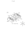
- FIG. 1 is an external perspective view of the first connector 10.
- FIG. 2 is an exploded perspective view of the first connector 10.
- FIG. 3 is a top view of the first connector 10.
- FIG. 4 is a top view of the plurality of terminals 14 of the connectors 210 and 310 according to the comparative example, and a top view of the plurality of terminals 14 of the first connectors 10, 10a and 10b.
- FIG. 5 is an external perspective view of the second connector 110.
- FIG. 6 is an exploded perspective view of the second connector 110.
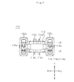
- FIG. 7 is a bottom view of the second connector 110.
- FIG. 1 is an external perspective view of the first connector 10.
- FIG. 2 is an exploded perspective view of the first connector 10.
- FIG. 3 is a top view of the first connector 10.
- the vertical direction, the horizontal direction, and the front-back direction are defined.
- the vertical direction, the horizontal direction, and the front-back direction are the directions defined for the sake of explanation. Therefore, the vertical direction, the horizontal direction, and the front-rear direction of the first connector 10 in actual use do not have to coincide with the vertical direction, the left-right direction, and the front-rear direction of FIGS. 1 to 3.
- the shafts and members extending in the front-rear direction do not necessarily indicate only the shafts and members that are parallel to the front-rear direction.
- a shaft or member extending in the front-rear direction is a shaft or member inclined in a range of ⁇ 45 ° with respect to the front-rear direction.
- a shaft or member extending in the vertical direction is a shaft or member inclined in a range of ⁇ 45 ° with respect to the vertical direction.
- a shaft or member extending in the left-right direction is a shaft or member inclined in a range of ⁇ 45 ° with respect to the left-right direction.
- the first member and the second member arranged in the front-rear direction indicate the following states.
- both the first member and the second member are arranged on an arbitrary straight line indicating the front-rear direction.
- the first member and the second member arranged in the front-rear direction when viewed in the vertical direction indicate the following states.
- both the first member and the second member are arranged on an arbitrary straight line indicating the front-rear direction.
- first member and the second member when the first member and the second member are viewed from a left-right direction different from the vertical direction, one of the first member and the second member may not be arranged on an arbitrary straight line indicating the front-rear direction. ..
- the first member and the second member may be in contact with each other.
- the first member and the second member may be separated from each other.
- a third member may be present between the first member and the second member. This definition also applies to directions other than the front-back direction.
- the first member to the third member are a part of the connector.
- the fact that the first member is arranged in front of the second member means the following state. At least a part of the first member is arranged in a region through which the second member translates in the forward direction. Therefore, the first member may be contained in the region through which the second member passes when it is translated in the forward direction, or protrudes from the region through which the second member is translated when it is translated in the forward direction. May be good. In this case, the first member and the second member are arranged in the front-rear direction. This definition also applies to directions other than the front-back direction.
- the first member when the first member is arranged in front of the second member when viewed in the left-right direction, it means the following state.
- the first member and the second member When viewed in the left-right direction, the first member and the second member are lined up in the front-rear direction, and when viewed in the left-right direction, the portion of the first member facing the second member is the second member. Placed in front.
- the first member and the second member do not have to be arranged in the front-rear direction in three dimensions. This definition applies to directions other than the front-back direction.
- the fact that the first member is arranged before the second member means the following state.
- the first member is arranged in front of a plane that passes through the front end of the second member and is orthogonal to the front-rear direction.
- the first member and the second member may or may not be arranged in the front-rear direction.
- This definition also applies to directions other than the front-back direction.
- each part of the first member is defined as follows.
- the front part of the first member means the front half of the first member.
- the rear part of the first member means the rear half of the first member.
- the left portion of the first member means the left half of the first member.
- the right portion of the first member means the right half of the first member.
- the upper part of the first member means the upper half of the first member.
- the lower part of the first member means the lower half of the first member.
- the front end of the first member means the end in the front direction of the first member.
- the rear end of the first member means the rear end of the first member.
- the left end of the first member means the left end of the first member.
- the right end of the first member means the right end of the first member.
- the upper end of the first member means the upper end of the first member.
- the lower end of the first member means the lower end of the first member.
- the front end portion of the first member means the front end portion of the first member and its vicinity.
- the rear end portion of the first member means the rear end portion of the first member and its vicinity.
- the left end portion of the first member means the left end portion of the first member and its vicinity.
- the right end portion of the first member means the right end portion of the first member and its vicinity.
- the upper end portion of the first member means the upper end portion of the first member and its vicinity.
- the lower end of the first member means the lower end of the first member and its vicinity.
- the first connector 10 is connected to the second connector 110, which will be described later.
- the first connector 10 is mounted on a circuit board such as a flexible board.
- the first connector 10 includes an insulating member 12, a plurality of terminals 14 (a plurality of terminals), high frequency terminals 16a and 16b, contact terminals 18a to 18f, and an external terminal 20.
- the insulating member 12 is a block having a rectangular shape when viewed downward.
- the insulating member 12 is made of, for example, an insulating resin such as a liquid crystal polymer.
- the insulating member 12 holds a plurality of terminals 14, high frequency terminals 16a and 16b, contact terminals 18a to 18f, and an external terminal 20.
- the insulating member 12 is integrated with the plurality of terminals 14, the high frequency terminals 16a and 16b, the contact terminals 18a to 18f, and the external terminal 20 by, for example, insert molding. Therefore, a plurality of terminals 14, high frequency terminals 16a and 16b, contact terminals 18a to 18f, and a part of the external terminals 20 are embedded in the insulating member 12.
- the external terminal 20 is a conductor connected to the ground potential.
- the external terminal 20 has a rectangular ring shape when viewed downward.
- the long side of the external terminal 20 extends in the left-right direction.
- the short side of the external terminal 20 extends in the front-rear direction.
- the external terminal 20 is manufactured by bending a single metal plate.
- the external terminal 20 is made of a copper-based material such as phosphor bronze.
- the external terminal 20 Since the external terminal 20 has a rectangular ring shape when viewed downward, it covers the vicinity of the front side, the vicinity of the rear side, the vicinity of the left side, and the vicinity of the right side of the upper surface of the insulating member 12. However, since the external terminal 20 has a rectangular ring shape when viewed downward, the central portion of the insulating member 12 is exposed from the external terminal 20 when viewed downward. There is. The external terminal 20 covers a part of the front surface, a part of the rear surface, a part of the left surface, and a part of the right surface of the insulating member 12.
- the plurality of terminals 14 include a first terminal 14a, a second terminal 14b, a third terminal 14c, and a fourth terminal 14d.
- the first terminal 14a, the second terminal 14b, the third terminal 14c, and the fourth terminal 14d are arranged near the center of the insulating member 12 from the outer edge of the insulating member 12 when viewed downward.
- the first terminal 14a and the second terminal 14b are arranged in the first row L1 extending in the left-right direction. That is, the first terminal 14a and the second terminal 14b are arranged in the left-right direction.
- the second terminal 14b is arranged to the right of the first terminal 14a. Further, the second terminal 14b is adjacent to the first terminal 14a. Therefore, no other terminal is arranged between the first terminal 14a and the second terminal 14b.
- the third terminal 14c and the fourth terminal 14d are arranged in the second row L2 extending in the left-right direction. That is, the third terminal 14c and the fourth terminal 14d are arranged in the left-right direction.
- the third terminal 14c is arranged to the right of the fourth terminal 14d. Further, the third terminal 14c is adjacent to the fourth terminal 14d. Therefore, no other terminal is arranged between the fourth terminal 14d and the third terminal 14c.
- the first row L1 is located after the second row L2.
- the first terminal 14a overlaps with the fourth terminal 14d when viewed in the front-rear direction.
- the first terminal 14a is arranged after the fourth terminal 14d.
- the fourth terminal 14d does not protrude in the left-right direction from the first terminal 14a when viewed in the front-rear direction.
- the second terminal 14b overlaps with the third terminal 14c when viewed in the front-rear direction.
- the second terminal 14b is arranged after the third terminal 14c.
- the second terminal 14b does not protrude in the left-right direction from the third terminal 14c when viewed in the front-rear direction.
- the first width W1 in the left-right direction of the first terminal 14a is larger than the second width W2 in the left-right direction of the second terminal 14b. Therefore, the conductor loss of the first terminal 14a is smaller than the conductor loss of the second terminal 14b.
- the third width W3 in the left-right direction of the third terminal 14c is larger than the fourth width W4 in the left-right direction of the fourth terminal 14d. Therefore, the conductor loss of the third terminal 14c is smaller than the conductor loss of the fourth terminal 14d.
- the first width W1 and the third width W3 are equal.
- the second width W2 and the fourth width W4 are equal.
- the first width W1 and the fourth width W4 are not equal.
- the second width W2 and the third width W3 are not equal.
- the first width W1 is the maximum value of the width of the first terminal 14a in the left-right direction.
- the second width W2 is the maximum value of the width of the second terminal 14b in the left-right direction.
- the third width W3 is the maximum value of the width of the third terminal 14c in the left-right direction.
- the fourth width W4 is the maximum value of the width of the fourth terminal 14d in the left-right direction. Further, the distance between the right end of the first terminal 14a and the left end of the second terminal 14b is equal to the distance between the left end of the third terminal 14c and the right end of the fourth terminal 14d.
- the first terminal 14a and the third terminal 14c are power supply terminals. Therefore, the first terminal 14a and the third terminal 14c are terminals connected to the power supply potential.
- the second terminal 14b and the fourth terminal 14d are terminals for digital signals. Therefore, the second terminal 14b and the fourth terminal 14d are terminals to which a digital signal (that is, a high frequency signal) is applied.
- the first terminal 14a, the second terminal 14b, the third terminal 14c, and the fourth terminal 14d have the same structure except that the widths in the left-right direction are different.
- the structures of the first terminal 14a, the second terminal 14b, the third terminal 14c, and the fourth terminal 14d will be described by taking the first terminal 14a as an example.
- the first terminal 14a includes a U-shaped portion 140a, a drawer portion 140b, and a connecting portion 140c.
- the U-shaped portion 140a has a U-shaped shape when viewed in the left-right direction. Therefore, the U-shaped portion 140a has a shape recessed downward.
- the inner surface of the U-shaped portion 140a is exposed from the insulating member 12 when viewed downward.
- the drawer portion 140b is located behind the bottom portion of the U-shaped portion 140a.
- the drawer portion 140b extends linearly in the front-rear direction.
- the rear end of the drawer 140b is exposed from the insulating member 12.
- the connecting portion 140c connects the rear end of the U-shaped portion 140a and the front end of the drawing portion 140b.
- Such a first terminal 14a is manufactured by bending a single metal plate.
- the first terminal 14a is made of a copper-based material such as phosphor bronze.
- the high frequency terminal 16a is arranged on the left side of the insulating member 12 when viewed downward.
- the high frequency terminal 16b is arranged on the right side of the insulating member 12 when viewed downward.
- the high frequency terminals 16a and 16b are terminals to which a high frequency signal is applied.
- the high frequency terminals 16a and 16b have the same structure.
- the structure of the high frequency terminals 16a and 16b will be described by taking the high frequency terminal 16a as an example.
- the high frequency terminal 16a includes an inverted U-shaped portion 160a and a drawer portion 160b.
- the inverted U-shaped portion 160a has a U-shape that is upside down when viewed in the left-right direction. Therefore, the inverted U-shaped portion 160a has a shape protruding upward.
- the outer surface of the inverted U-shaped portion 160a is exposed from the insulating member 12 when viewed downward.
- the drawer portion 160b extends linearly in the forward direction from the front end of the inverted U-shaped portion 160a.
- the front end portion of the drawer portion 160b is exposed from the insulating member 12.
- Such a high frequency terminal 16a is manufactured by bending a single metal plate.
- the high frequency terminal 16a is made of a copper-based material such as phosphor bronze.
- the contact terminals 18a to 18c are arranged on the left side of the insulating member 12 when viewed downward.
- the contact terminal 18a is arranged to the left of the high frequency terminal 16a.
- the contact terminal 18b is arranged in front of the high frequency terminal 16a on the right side.
- the contact terminal 18c is arranged on the right rear side of the high frequency terminal 16a.
- the contact terminals 18d to 18f are arranged on the right side of the insulating member 12 when viewed downward.
- the contact terminal 18d is arranged to the right of the high frequency terminal 16b.
- the contact terminal 18e is arranged in front of the left side of the high frequency terminal 16b.
- the contact terminal 18f is arranged behind the high frequency terminal 16b to the left.
- the contact terminals 18a and 18b are terminals connected to the ground potential.
- the contact terminals 18a and 18b are manufactured by bending a single metal plate.
- the contact terminals 18a and 18b are made of a copper-based material
- the first connector 10 configured as described above is mounted on the circuit board. Specifically, a plurality of terminals 14, high-frequency terminals 16a and 16b, contact terminals 18a to 18f, and an external terminal 20 are connected to a land electrode provided on a circuit board by soldering.
- FIG. 4 is a top view of the plurality of terminals 14 of the connectors 210 and 310 according to the comparative example, and a top view of the plurality of terminals 14 of the first connectors 10, 10a and 10b.
- the first connectors 10a and 10b are modified examples of the first connector 10. Note that FIG. 4 is schematic. Therefore, the sizes of the plurality of terminals 14 in FIG. 4 do not match the sizes of the plurality of terminals 14 in FIGS. 1 to 3. Further, the connectors 210 and 310 are not included in the connector according to the present invention.
- first distance D1 half of the value obtained by subtracting the fourth width W4 from the first width W1 is defined as the first distance D1.
- Half of the value obtained by subtracting the second width W2 from the third width W3 is defined as the second distance D2.
- the first terminal 14a, the second terminal 14b, the third terminal 14c, and the fourth terminal 14d satisfy the conditions of (A) and (B), or the conditions of (C) and (D) are satisfied. Arranged to meet.
- the left end of the first terminal 14a is located to the left of the left end of the fourth terminal 14d, and the distance d1 in the left-right direction between the left end of the first terminal 14a and the left end of the fourth terminal 14d is the first.
- the distance is shorter than D1, or (a2) the left end of the first terminal 14a coincides with the left end of the fourth terminal 14d in the left-right direction.
- the right end of the second terminal 14b is located to the left of the right end of the third terminal 14c, and the distance d2 between the right end of the second terminal 14b and the right end of the third terminal 14c in the left-right direction is the second. It is shorter than the distance D2, or (b2) the right end of the second terminal 14b coincides with the right end of the third terminal 14c in the left-right direction.
- the left end of the fourth terminal 14d is located to the left of the left end of the first terminal 14a, and the distance d1 between the left end of the first terminal 14a and the left end of the fourth terminal 14d in the left-right direction is the second. It is shorter than the distance D2, or (c2) the left end of the first terminal 14a coincides with the left end of the fourth terminal 14d in the left-right direction.
- the right end of the third terminal 14c is located to the left of the right end of the second terminal 14b, and the distance d2 between the right end of the second terminal 14b and the right end of the third terminal 14c in the left-right direction is the first.
- the distance is shorter than D1, or (d2) the right end of the second terminal 14b coincides with the right end of the third terminal 14c in the left-right direction.
- the first terminal 14a, the second terminal 14b, the third terminal 14c, and the fourth terminal 14d are arranged so as to satisfy the conditions (A) and (B).
- the left end of the fourth terminal 14d is arranged closer to the left end of the first terminal 14a than the center in the left-right direction of the first terminal 14a.
- the right end of the second terminal 14b is arranged closer to the right end of the third terminal 14c than the center in the left-right direction of the third terminal 14c.
- the first terminal 14a, the second terminal 14b, the third terminal 14c, and the fourth terminal 14d satisfy the conditions of (a2) of (A) and (b2) of (B). , Have been placed.
- the first terminal 14a, the second terminal 14b, the third terminal 14c and the fourth terminal 14d are of (a1) of (A) and (b1) of (B). It may be arranged so as to satisfy the conditions. That is, the left end of the first terminal 14a may be located slightly to the left of the left end of the fourth terminal 14d, and the right end of the second terminal 14b may be located slightly to the left of the right end of the third terminal 14c.
- the distance d1 in the left-right direction between the left end of the first terminal 14a and the left end of the fourth terminal 14d must not be equal to the first distance D1.
- the distance d2 between the right end of the second terminal 14b and the right end of the third terminal 14c in the left-right direction must not be equal to the second distance D2.
- the first terminal 14a, the second terminal 14b, the third terminal 14c, and the fourth terminal 14d are of (c1) of (C) and (d1) of (D). It may be arranged so as to satisfy the conditions. That is, the left end of the fourth terminal 14d may be located slightly to the left of the left end of the first terminal 14a, and the right end of the third terminal 14c may be located slightly to the left of the right end of the second terminal 14b.
- the distance d1 in the left-right direction between the left end of the first terminal 14a and the left end of the fourth terminal 14d must not be equal to the second distance D2.
- the distance d2 in the left-right direction between the right end of the second terminal 14b and the right end of the third terminal 14c must not be equal to the first distance D1.
- FIG. 5 is an external perspective view of the second connector 110.
- FIG. 6 is an exploded perspective view of the second connector 110.
- FIG. 7 is a bottom view of the second connector 110.
- the vertical direction, the horizontal direction, and the front-back direction are defined.
- the vertical direction, the horizontal direction, and the front-back direction are the directions defined for the sake of explanation. Therefore, the vertical direction, the horizontal direction, and the front-rear direction in the actual use of the second connector 110 do not have to coincide with the vertical direction, the left-right direction, and the front-rear direction of FIGS. 5 to 7.
- the second connector 110 is connected to the first connector 10.
- the second connector 110 is mounted on a circuit board such as a flexible board.
- the second connector 110 includes an insulating member 112, a plurality of terminals 114, high frequency terminals 116a and 116b, and external terminals 120a and 120b.
- the insulating member 112 includes a rear connecting portion 112a, a front connecting portion 112b, a left portion 112c, and a right portion 112d.
- the left portion 112c and the right portion 112d have a rectangular shape when viewed upward.
- the right portion 112d is arranged to the right of the left portion 112c.
- the rear connecting portion 112a extends in the left-right direction.
- the rear connecting portion 112a connects the left portion 112c and the right portion 112d.
- the front connecting portion 112b extends in the left-right direction.
- the front connecting portion 112b connects the left portion 112c and the right portion 112d.
- the front connecting portion 112b is arranged in front of the rear connecting portion 112a.
- the insulating member 112 is made of, for example, an insulating resin such as a liquid crystal polymer.
- the insulating member 112 holds a plurality of terminals 114, high frequency terminals 116a and 116b, and external terminals 120a and 120b.
- the insulating member 112 is integrated with a plurality of terminals 114, high frequency terminals 116a and 116b, and external terminals 120a and 120b by insert molding. Therefore, a part of the plurality of terminals 114, the high frequency terminals 116a and 116b, and the external terminals 120a and 120b are embedded in the insulating member 112.
- the external terminals 120a and 120b are conductors connected to the ground potential.
- the external terminals 120a and 120b have a rectangular ring shape when viewed upward.
- the long sides of the external terminals 120a and 120b extend in the front-rear direction.
- the short sides of the external terminals 120a and 120b extend in the left-right direction.
- the external terminals 120a and 120b are manufactured by bending a single metal plate.
- the external terminals 120a and 120b are made of a copper-based material such as phosphor bronze.
- the external terminal 120a Since the external terminal 120a has a rectangular ring shape when viewed upward, it covers the vicinity of the front side, the vicinity of the rear side, the vicinity of the left side, and the vicinity of the right side of the upper surface of the left portion 112c of the insulating member 112. ing. However, since the external terminal 120a has a rectangular ring shape when viewed upward, the central portion of the left portion 112c of the insulating member 12 is the external terminal 120a when viewed upward. It is exposed from. The external terminal 120a covers a part of the front surface, a part of the rear surface, a part of the left surface, and a part of the right surface of the left portion 112c of the insulating member 112.
- the external terminal 120b Since the external terminal 120b has a rectangular ring shape when viewed upward, it covers the vicinity of the front side, the vicinity of the rear side, the vicinity of the left side, and the vicinity of the right side of the upper surface of the right portion 112d of the insulating member 112. ing. However, since the external terminal 120b has a rectangular ring shape when viewed upward, the central portion of the right portion 112d of the insulating member 112 is the external terminal 120b when viewed upward. It is exposed from. The external terminal 120b covers a part of the front surface, a part of the rear surface, a part of the left surface, and a part of the right surface of the right portion 112d of the insulating member 112.
- the plurality of terminals 114 include a first terminal 114a, a second terminal 114b, a third terminal 114c, and a fourth terminal 114d.
- the first terminal 114a, the second terminal 114b, the third terminal 114c, and the fourth terminal 114d are arranged near the center of the insulating member 112 from the outer edge of the insulating member 112 when viewed upward.
- the first terminal 114a and the second terminal 114b are held by the rear connecting portion 112a.
- the third terminal 114c and the fourth terminal 114d are held by the front connecting portion 112b.
- the first terminal 114a and the second terminal 114b are arranged in the first row L3 extending in the left-right direction. That is, the first terminal 114a and the second terminal 114b are arranged in the left-right direction.
- the second terminal 114b is arranged to the right of the first terminal 114a. Further, the second terminal 114b is adjacent to the first terminal 114a. Therefore, no other terminal is arranged between the first terminal 114a and the second terminal 114b.
- the third terminal 114c and the fourth terminal 114d are arranged in the second row L4 extending in the left-right direction. That is, the third terminal 114c and the fourth terminal 114d are arranged in the left-right direction.
- the third terminal 114c is arranged to the right of the fourth terminal 114d. Further, the third terminal 114c is adjacent to the fourth terminal 114d. Therefore, no other terminal is arranged between the fourth terminal 114d and the third terminal 114c.
- the first row L3 is located after the second row L4.
- the first terminal 114a overlaps with the fourth terminal 114d when viewed in the front-rear direction.
- the first terminal 114a is arranged after the fourth terminal 114d.
- the fourth terminal 114d does not protrude in the left-right direction from the first terminal 114a when viewed in the front-rear direction.
- the second terminal 114b overlaps with the third terminal 114c when viewed in the front-rear direction.
- the second terminal 114b is arranged after the third terminal 114c.
- the second terminal 114b does not protrude in the left-right direction from the third terminal 114c when viewed in the front-rear direction.
- the first width W1 in the left-right direction of the first terminal 114a is larger than the second width W2 in the left-right direction of the second terminal 114b. Therefore, the conductor loss of the first terminal 114a is smaller than the conductor loss of the second terminal 114b.
- the third width W3 in the left-right direction of the third terminal 114c is larger than the fourth width W4 in the left-right direction of the fourth terminal 114d. Therefore, the conductor loss of the third terminal 114c is smaller than the conductor loss of the fourth terminal 114d.
- the first width W1 and the third width W3 are equal.
- the second width W2 and the fourth width W4 are equal.
- the first width W1 is the maximum value of the width of the first terminal 114a in the left-right direction.
- the second width W2 is the maximum value of the width of the second terminal 114b in the left-right direction.
- the third width W3 is the maximum value of the width of the third terminal 114c in the left-right direction.
- the fourth width W4 is the maximum value of the width of the fourth terminal 114d in the left-right direction. Further, the distance between the right end of the first terminal 114a and the left end of the second terminal 114b is equal to the distance between the left end of the third terminal 114c and the right end of the fourth terminal 114d.
- the first terminal 114a and the third terminal 114c are power supply terminals. Therefore, the first terminal 114a and the third terminal 114c are terminals connected to the power supply potential.
- the second terminal 114b and the fourth terminal 114d are terminals for digital signals. Therefore, the second terminal 114b and the fourth terminal 114d are terminals to which a digital signal (that is, a high frequency signal) is applied.
- the first terminal 114a, the second terminal 114b, the third terminal 114c, and the fourth terminal 114d have the same structure except that the widths in the left-right direction are different.
- the structures of the first terminal 114a, the second terminal 114b, the third terminal 114c, and the fourth terminal 114d will be described by taking the first terminal 114a as an example.
- the first terminal 114a includes a U-shaped portion 1140a and a drawer portion 1140b.
- the U-shaped portion 1140a has a U-shape when viewed in the left-right direction. Therefore, the U-shaped portion 1140a has a shape protruding downward.
- the outer surface of the U-shaped portion 1140a is exposed from the insulating member 112 when viewed upward.
- the drawer portion 1140b extends linearly from the rear end of the U-shaped portion 1140a in the rear direction.
- the rear end of the drawer 1140b is exposed from the insulating member 112.
- Such a first terminal 114a is manufactured by bending a single metal plate.
- the first terminal 114a is made of a copper-based material such as phosphor bronze.
- the high frequency terminal 116a is arranged on the left portion 112c of the insulating member 112 when viewed upward.
- the high frequency terminal 116b is arranged on the right side 112d of the insulating member 112 when viewed upward.
- the high frequency terminals 116a and 116b are terminals to which a high frequency signal is applied.
- the high frequency terminals 116a and 116b have the same structure.
- the structures of the high frequency terminals 116a and 116b will be described by taking the high frequency terminal 116a as an example.
- the high frequency terminal 116a includes an inverted U-shaped portion 1160a, a pull-out portion 1160b, and a connecting portion 1160c.
- the inverted U-shaped portion 1160a has a U-shape that is upside down when viewed in the left-right direction. Therefore, the inverted U-shaped portion 1160a has an upwardly recessed shape.
- the inner surface of the inverted U-shaped portion 1160a is exposed from the insulating member 112 when viewed upward.
- the drawer portion 1160b is located in front of the bottom portion of the inverted U-shaped portion 1160a.
- the drawer portion 1160b extends linearly in the front-rear direction. The front end of the drawer 1160b is exposed from the insulating member 112.
- the connecting portion 1160c connects the front end of the inverted U-shaped portion 1160a and the rear end of the drawer portion 1160b.
- a first terminal 114a is manufactured by bending a single metal plate.
- the first terminal 114a is made of a copper-based material such as phosphor bronze.
- the second connector 110 configured as described above is mounted on the circuit board. Specifically, a plurality of terminals 114, high-frequency terminals 116a and 116b, and external terminals 120a and 120b are connected to the land electrodes provided on the circuit board by soldering.
- the details of the arrangement of the plurality of terminals 114 as described above are the same as the details of the arrangement of the plurality of terminals 14 in FIG. Therefore, the details of the arrangement of the plurality of terminals 114 will be omitted.
- the first connector 10 and the second connector 110 configured as described above are connected to each other. Specifically, the second connector 110 is arranged on the first connector 10. Then, the second connector 110 is moved downward. The external terminal 120a is inserted in the left portion of the area surrounded by the external terminal 20. At this time, the external terminals 20 and the contact terminals 18a to 18c come into contact with the external terminals 120a. Further, the external terminal 120b is inserted into the right portion of the area surrounded by the external terminal 20. At this time, the external terminal 20 and the contact terminals 18d to 18f are connected to the external terminal 120b.
- the high frequency terminals 16a and 16b are connected to the high frequency terminals 116a and 116b, respectively.
- the first terminal 14a, the second terminal 14b, the third terminal 14c and the fourth terminal 14d are connected to the first terminal 114a, the second terminal 114b, the third terminal 114c and the fourth terminal 114d, respectively.
- the first width W1 in the left-right direction of the first terminal 14a is larger than the second width W2 in the left-right direction of the second terminal 14b.
- the third width W3 in the left-right direction of the third terminal 14c is larger than the fourth width W4 in the left-right direction of the fourth terminal 14d.
- the first terminal 14a overlaps with the fourth terminal 14d when viewed in the front-rear direction.
- the second terminal 14b overlaps with the third terminal 14c when viewed in the front-rear direction.
- two terminals having different sizes are arranged in the front-rear direction.
- the degree of freedom in layout of the plurality of terminals 14 can be increased.
- the first connector 10 it is possible to suppress the increase in size of the first connector 10. More specifically, when two terminals having different sizes are arranged in the front-rear direction, an arrangement like the connector 210 in FIG. 4 is adopted. Specifically, the center of the first terminal 14a in the left-right direction and the center of the fourth terminal 14d in the left-right direction coincide with each other. The center of the second terminal 14b in the left-right direction coincides with the center of the third terminal 14c in the left-right direction.
- the length of the plurality of terminals 14 in the left-right direction is the sum of the distance from the right end of the third terminal 14c to the left end of the fourth terminal 14d and the first distance D1, or the length from the left end of the first terminal 14a to the first. It is the sum of the distance to the right end of the two terminals 14b and the second distance D2. Therefore, in the connector 210, the lengths of the plurality of terminals 14 in the left-right direction become long.
- the first terminal 14a, the second terminal 14b, the third terminal 14c, and the fourth terminal 14d satisfy the conditions of (A) and (B), or satisfy the conditions of (C) and (D). It is arranged so that.
- the left end of the first terminal 14a is located to the left of the left end of the fourth terminal 14d, and the distance d1 in the left-right direction between the left end of the first terminal 14a and the left end of the fourth terminal 14d is the first.
- the distance is shorter than D1, or (a2) the left end of the first terminal 14a coincides with the left end of the fourth terminal 14d in the left-right direction.
- the right end of the second terminal 14b is located to the left of the right end of the third terminal 14c, and the distance d2 between the right end of the second terminal 14b and the right end of the third terminal 14c in the left-right direction is the second. It is shorter than the distance D2, or (b2) the right end of the second terminal 14b coincides with the right end of the third terminal 14c in the left-right direction.
- the left end of the fourth terminal 14d is located to the left of the left end of the first terminal 14a, and the distance d1 between the left end of the first terminal 14a and the left end of the fourth terminal 14d in the left-right direction is the second. It is shorter than the distance D2, or (c2) the left end of the first terminal 14a coincides with the left end of the fourth terminal 14d in the left-right direction.
- the right end of the third terminal 14c is located to the left of the right end of the second terminal 14b, and the distance d2 between the right end of the second terminal 14b and the right end of the third terminal 14c in the left-right direction is the first.
- the distance is shorter than D1, or (d2) the right end of the second terminal 14b coincides with the right end of the third terminal 14c in the left-right direction.
- the position of the left end of the fourth terminal 14d with respect to the position of the left end of the first terminal 14a is defined as x.
- the position of the left end of the first terminal 14a is set to 0.
- x takes a positive value when the left end of the fourth terminal 14d is located to the left of the left end of the first terminal 14a.
- x takes a negative value when the left end of the fourth terminal 14d is located to the right of the left end of the first terminal 14a.
- the position of the right end of the third terminal 14c with respect to the position of the right end of the second terminal 14b is defined as y.
- the position at the right end of the second terminal 14b is set to 0.
- y takes a negative value when the right end of the third terminal 14c is located to the left of the right end of the second terminal 14b.
- y takes a positive value when the right end of the third terminal 14c is located to the right of the right end of the second terminal 14b.
- the first terminal 14a, the second terminal 14b, the third terminal 14c, and the fourth terminal 14d satisfy the equations (1) and (2), or the equations (3) and (4) are expressed. Arranged to meet.
- the length of the plurality of terminals 14 in the left-right direction is the sum of the distance from the right end of the third terminal 14c to the left end of the fourth terminal 14d and the distance d1.
- the distance d1 is shorter than the first distance D1.
- the length of the plurality of terminals 14 of the first connector 10 in the left-right direction is shorter than the length of the plurality of terminals 14 of the connector 210 in the left-right direction. Therefore, the increase in size of the first connector 10 is suppressed.
- the length of the plurality of terminals 14 in the left-right direction is the sum of the distance from the right end of the third terminal 14c to the left end of the fourth terminal 14d and the distance d2.
- the distance d2 is shorter than the first distance D1. Therefore, the length of the plurality of terminals 14 of the first connector 10 in the left-right direction is shorter than the length of the plurality of terminals 14 of the connector 210 in the left-right direction. Therefore, the increase in size of the first connector 10 is suppressed.
- the left end of the fourth terminal 14d is arranged closer to the left end of the first terminal 14a than the center in the left-right direction of the first terminal 14a.
- the distance d1 becomes shorter.
- the right end of the second terminal 14b is arranged closer to the right end of the third terminal 14c than the center in the left-right direction of the third terminal 14c. Therefore, the distance d2 becomes short.
- the lengths of the plurality of terminals 14 of the first connector 10 in the left-right direction are shortened. Therefore, the increase in size of the first connector 10 is further suppressed.
- the first connector 10 it is possible to further suppress the increase in size of the first connector 10. More specifically, the left end of the first terminal 14a coincides with the left end of the fourth terminal 14d in the left-right direction. The right end of the second terminal 14b coincides with the right end of the third terminal 14c in the left-right direction. In this case, the distances d1 and d2 are 0. As a result, the length of the plurality of terminals 14 of the first connector 10 in the left-right direction is the distance from the right end of the third terminal 14c to the left end of the fourth terminal 14d. Therefore, the lengths of the plurality of terminals 14 of the first connector 10 in the left-right direction are minimized. From the above, according to the first connector 10, it is possible to further suppress the increase in size of the first connector 10.
- the structures of the first connectors 10, 10a, and 10b may be arbitrarily combined. Further, the structure of the first connectors 10, 10a and 10b may be used for the second connector 110.
- the first row L1 may be located in front of the second row L2. Further, in the second connector 110, the first row L3 may be located in front of the second row L4.
- the plurality of terminals 14 may include a plurality of sets of the first terminal 14a, the second terminal 14b, the third terminal 14c, and the fourth terminal 14d. Therefore, a plurality of sets of the first terminal 14a, the second terminal 14b, the third terminal 14c, and the fourth terminal 14d may be arranged in the left-right direction.
- the plurality of terminals 114 may include a plurality of sets of the first terminal 114a, the second terminal 114b, the third terminal 114c, and the fourth terminal 114d. Therefore, a plurality of sets of the first terminal 114a, the second terminal 114b, the third terminal 114c, and the fourth terminal 114d may be arranged in the left-right direction.
- the first terminals 14a and 114a and the third terminals 14c and 114c may be terminals for digital signals. Further, the second terminals 14b and 114b and the fourth terminals 14d and 114d may be power supply terminals.
- first width W1 in the left-right direction of the first terminal 14a and the third width W3 in the left-right direction of the third terminal 14c do not have to be equal.
- second width W2 in the left-right direction of the second terminal 14b and the fourth width W4 in the left-right direction of the fourth terminal 14d do not have to be equal.
- the distance from the left end of the first terminal 14a to the right end of the second terminal 14b is preferably equal to the distance from the left end of the fourth terminal 14d to the right end of the third terminal 14c.
- first width W1 in the left-right direction of the first terminal 14a and the third width W3 in the left-right direction of the third terminal 14c are not equal, and the second width W2 and the fourth terminal in the left-right direction of the second terminal 14b are not equal. It may be equal to the fourth width W4 in the left-right direction of 14d. Further, the first width W1 in the left-right direction of the first terminal 14a and the third width W3 in the left-right direction of the third terminal 14c are equal to each other, and the second width W2 and the fourth terminal 14d in the left-right direction of the second terminal 14b are equal. It does not have to be equal to the fourth width W4 in the left-right direction of. Also in these cases, the distance from the left end of the first terminal 14a to the right end of the second terminal 14b is preferably equal to the distance from the left end of the fourth terminal 14d to the right end of the third terminal 14c.
- the first width W1 in the left-right direction of the first terminal 114a and the third width W3 in the left-right direction of the third terminal 114c do not have to be equal.
- the second width W2 in the left-right direction of the second terminal 114b and the fourth width W4 in the left-right direction of the fourth terminal 114d do not have to be equal.
- the distance from the left end of the first terminal 114a to the right end of the second terminal 114b is preferably equal to the distance from the left end of the fourth terminal 114d to the right end of the third terminal 114c.
- first width W1 in the left-right direction of the first terminal 114a and the third width W3 in the left-right direction of the third terminal 114c are not equal, and the second width W2 and the fourth terminal in the left-right direction of the second terminal 114b are not equal. It may be equal to the fourth width W4 in the left-right direction of 114d. Further, the first width W1 in the left-right direction of the first terminal 114a and the third width W3 in the left-right direction of the third terminal 114c are equal to each other, and the second width W2 and the fourth terminal 114d in the left-right direction of the second terminal 114b are equal. It does not have to be equal to the fourth width W4 in the left-right direction of. Also in these cases, the distance from the left end of the first terminal 114a to the right end of the second terminal 114b is preferably equal to the distance from the left end of the fourth terminal 114d to the right end of the third terminal 114c.
- the plurality of terminals 14 may include a plurality of fifth terminals and a plurality of sixth terminals.
- the plurality of fifth terminals are arranged in the first row L1 extending in the left-right direction.
- the plurality of fifth terminals are arranged to the right of the first terminal 14a and to the left of the second terminal 14b.
- the fifth width of the plurality of fifth terminals in the left-right direction is uniform.
- the plurality of sixth terminals are arranged in the second row L2 extending to the left and right.
- the plurality of sixth terminals are arranged to the right of the fourth terminal 14d and to the left of the third terminal 14c.
- the sixth width of the plurality of sixth terminals in the left-right direction is uniform. In this way, a plurality of fifth terminals may be provided between the first terminal 14a and the second terminal 14b. A plurality of sixth terminals may be provided between the third terminal 14c and the fourth terminal 14d.
- the plurality of terminals 114 may include a plurality of fifth terminals and a plurality of sixth terminals.
- the plurality of fifth terminals are arranged in the first row L3 extending in the left-right direction.
- the plurality of fifth terminals are arranged to the right of the first terminal 114a and to the left of the second terminal 114b.
- the fifth width of the plurality of fifth terminals in the left-right direction is uniform.
- the plurality of sixth terminals are arranged in the second row L4 extending to the left and right.
- the plurality of sixth terminals are arranged to the right of the fourth terminal 114d and to the left of the third terminal 114c.
- the sixth width of the plurality of sixth terminals in the left-right direction is uniform. In this way, a plurality of fifth terminals may be provided between the first terminal 114a and the second terminal 114b. A plurality of sixth terminals may be provided between the third terminal 114c and the fourth terminal 114d.
- the first connectors 10, 10a, 10b and the second connector 110 which do not have the plurality of fifth terminals and the plurality of sixth terminals, are more connectors than the connectors having the plurality of fifth terminals and the plurality of sixth terminals. The effect of suppressing the increase in size is great.
Abstract
A first terminal, a second terminal, a third terminal, and a fourth terminal are arranged so as to satisfy conditions (A) and (B). Condition (A): (a1) the left end of the first terminal is located to the left of the left end of the fourth terminal, and the lateral distance between the left end of the first terminal and the left end of the fourth terminal is shorter than a first distance, or (a2) the left end of the first terminal is aligned laterally with the left end of the fourth terminal. Condition (B): (b1) the right end of the second terminal is located to the left of the right end of the third terminal, and the lateral distance between the right end of the second terminal and the right end of the third terminal is shorter than a second distance, or (b2) the right end of the second terminal is aligned laterally with the right end of the third terminal.
Description
本発明は、サイズの異なる複数の端子を備えるコネクタに関する。
The present invention relates to a connector having a plurality of terminals having different sizes.
従来のコネクタに関する発明としては、例えば、特許文献1に記載のコネクタが知られている。特許文献1に記載のコネクタは、左右方向に延びる第1列に並ぶ複数の第1端子と左右方向に延びる第2列に並ぶ複数の第2端子を含んでいる。複数の第1端子は、複数の第1端子の内の左端に位置する左端第1端子、及び、複数の第1端子の内の右端に位置する右端第1端子を含んでいる。左端第1端子及び右端第1端子は、左端第1端子及び右端第1端子以外の第1端子(中間第1端子)より大きい。複数の第2端子は、複数の第2端子の内の左端に位置する左端第2端子、及び、複数の第2端子の内の右端に位置する右端第2端子を含んでいる。左端第2端子及び右端第2端子は、左端第2端子及び右端第2端子以外の第2端子(中間第2端子)より大きい。
As an invention relating to a conventional connector, for example, the connector described in Patent Document 1 is known. The connector described in Patent Document 1 includes a plurality of first terminals arranged in a first row extending in the left-right direction and a plurality of second terminals arranged in a second row extending in the left-right direction. The plurality of first terminals include a left end first terminal located at the left end of the plurality of first terminals and a right end first terminal located at the right end of the plurality of first terminals. The leftmost first terminal and the rightmost first terminal are larger than the first terminals (intermediate first terminals) other than the leftmost first terminal and the rightmost first terminal. The plurality of second terminals include a left end second terminal located at the left end of the plurality of second terminals and a right end second terminal located at the right end of the plurality of second terminals. The leftmost second terminal and the rightmost second terminal are larger than the second terminal (intermediate second terminal) other than the leftmost second terminal and the rightmost second terminal.
端子のレイアウトの自由度を高くしたいという要望がある。具体的には、特許文献1に記載のコネクタでは、小さい端子である中間第1端子と小さい端子である中間第2端子とが前後方向に並んでいる。このような特許文献1に記載のコネクタの端子の配列を、例えば、左端第1端子及び右端第1端子のような大きい端子と中間第1端子及び中間第2端子のような小さい端子とを前後方向に並べるように変更したい場合がある。
There is a desire to increase the degree of freedom in terminal layout. Specifically, in the connector described in Patent Document 1, the intermediate first terminal, which is a small terminal, and the intermediate second terminal, which is a small terminal, are arranged in the front-rear direction. The arrangement of the connector terminals described in Patent Document 1 is arranged by, for example, a large terminal such as the leftmost first terminal and the rightmost first terminal and a small terminal such as the intermediate first terminal and the intermediate second terminal. You may want to change it so that it is aligned in the direction.
また、複数種類の大きさを有する端子を備えたコネクタにおいて、端子間の距離を所望の距離に保ったまま、コネクタの大型化を抑制したいという要望が存在する。
Further, in a connector having terminals having a plurality of sizes, there is a demand for suppressing the increase in size of the connector while keeping the distance between the terminals at a desired distance.
そこで、本発明の目的は、複数の端子のレイアウトの自由度を高くすると共に、コネクタの大型化を抑制できるコネクタを提供することである。
Therefore, an object of the present invention is to provide a connector capable of increasing the degree of freedom in layout of a plurality of terminals and suppressing an increase in the size of the connector.
第1の発明に係るコネクタは、
複数の端子と、
前記複数の端子を保持する絶縁部材と、
を備えており、
前記複数の端子は、左右方向に延びる第1列に配置される第1端子及び第2端子を含んでおり、
前記複数の端子は、左右方向に延びる第2列に配置される第3端子及び第4端子を含んでおり、
前記第1列は、前記第2列の前又は後に位置しており、
前記第2端子は、前記第1端子の右に配置され、かつ、前記第1端子と隣り合っており、
前記第3端子は、前記第4端子の右に配置され、かつ、前記第4端子と隣り合っており、
前記第1端子は、前後方向に見たときに、前記第4端子と重なっており、
前記第2端子は、前後方向に見たときに、前記第3端子と重なっており、
前記第1端子の左右方向の第1幅は、前記第2端子の左右方向の第2幅より大きく、
前記第3端子の左右方向の第3幅は、前記第4端子の左右方向の第4幅より大きく、
前記第1幅から前記第4幅を減算した値の半分を第1距離と定義し、
前記第3幅から前記第2幅を減算した値の半分を第2距離と定義し、
前記第1端子、前記第2端子、前記第3端子及び前記第4端子は、(A)及び(B)の条件を満たすように、配置されており、
(A)(a1)前記第1端子の左端が前記第4端子の左端より左に位置し、かつ、前記第1端子の左端と前記第4端子の左端との左右方向における距離が前記第1距離より短い、又は、(a2)前記第1端子の左端が前記第4端子の左端と左右方向において一致し、
(B)(b1)前記第2端子の右端が前記第3端子の右端より左に位置し、かつ、前記第2端子の右端と前記第3端子の右端との左右方向における距離が前記第2距離より短い、又は、(b2)前記第2端子の右端が前記第3端子の右端と左右方向において一致する。 The connector according to the first invention is
With multiple terminals
Insulating member holding the plurality of terminals and
Is equipped with
The plurality of terminals include a first terminal and a second terminal arranged in a first row extending in the left-right direction.
The plurality of terminals include a third terminal and a fourth terminal arranged in a second row extending in the left-right direction.
The first row is located before or after the second row.
The second terminal is arranged to the right of the first terminal and is adjacent to the first terminal.
The third terminal is arranged to the right of the fourth terminal and is adjacent to the fourth terminal.
The first terminal overlaps with the fourth terminal when viewed in the front-rear direction.
The second terminal overlaps with the third terminal when viewed in the front-rear direction.
The first width of the first terminal in the left-right direction is larger than the second width of the second terminal in the left-right direction.
The third width in the left-right direction of the third terminal is larger than the fourth width in the left-right direction of the fourth terminal.
Half of the value obtained by subtracting the fourth width from the first width is defined as the first distance.
Half of the value obtained by subtracting the second width from the third width is defined as the second distance.
The first terminal, the second terminal, the third terminal, and the fourth terminal are arranged so as to satisfy the conditions (A) and (B).
(A) (a1) The left end of the first terminal is located to the left of the left end of the fourth terminal, and the distance between the left end of the first terminal and the left end of the fourth terminal in the left-right direction is the first. It is shorter than the distance, or (a2) the left end of the first terminal coincides with the left end of the fourth terminal in the left-right direction.
(B) (b1) The right end of the second terminal is located to the left of the right end of the third terminal, and the distance between the right end of the second terminal and the right end of the third terminal in the left-right direction is the second. It is shorter than the distance, or (b2) the right end of the second terminal coincides with the right end of the third terminal in the left-right direction.
第2の発明に係るコネクタは、
複数の端子と、
前記複数の端子を保持する絶縁部材と、
を備えており、
前記複数の端子は、左右方向に延びる第1列に配置される第1端子及び第2端子を含んでおり、
前記複数の端子は、左右方向に延びる第2列に配置される第3端子及び第4端子を含んでおり、
前記第1列は、前記第2列の前又は後に位置しており、
前記第2端子は、前記第1端子の右に配置され、かつ、前記第1端子と隣り合っており、
前記第3端子は、前記第4端子の右に配置され、かつ、前記第4端子と隣り合っており、
前記第1端子は、前後方向に見たときに、前記第4端子と重なっており、
前記第2端子は、前後方向に見たときに、前記第3端子と重なっており、
前記第1端子の左右方向の第1幅は、前記第2端子の左右方向の第2幅より大きく、
前記第3端子の左右方向の第3幅は、前記第4端子の左右方向の第4幅より大きく、
前記第1幅から前記第4幅を減算した値の半分を第1距離と定義し、
前記第3幅から前記第2幅を減算した値の半分を第2距離と定義し、
前記第1端子、前記第2端子、前記第3端子及び前記第4端子は、(C)及び(D)の条件を満たすように、配置されており、
(C)(c1)前記第4端子の左端が前記第1端子の左端より左に位置し、かつ、前記第1端子の左端と前記第4端子の左端との左右方向における距離が前記第2距離より短い、又は、(c2)前記第1端子の左端が前記第4端子の左端と左右方向において一致し、
(D)(d1)前記第3端子の右端が前記第2端子の右端より左に位置し、かつ、前記第2端子の右端と前記第3端子の右端との左右方向における距離が前記第1距離より短い、又は、(d2)前記第2端子の右端が前記第3端子の右端と左右方向において一致する。 The connector according to the second invention is
With multiple terminals
Insulating member holding the plurality of terminals and
Is equipped with
The plurality of terminals include a first terminal and a second terminal arranged in a first row extending in the left-right direction.
The plurality of terminals include a third terminal and a fourth terminal arranged in a second row extending in the left-right direction.
The first row is located before or after the second row.
The second terminal is arranged to the right of the first terminal and is adjacent to the first terminal.
The third terminal is arranged to the right of the fourth terminal and is adjacent to the fourth terminal.
The first terminal overlaps with the fourth terminal when viewed in the front-rear direction.
The second terminal overlaps with the third terminal when viewed in the front-rear direction.
The first width of the first terminal in the left-right direction is larger than the second width of the second terminal in the left-right direction.
The third width in the left-right direction of the third terminal is larger than the fourth width in the left-right direction of the fourth terminal.
Half of the value obtained by subtracting the fourth width from the first width is defined as the first distance.
Half of the value obtained by subtracting the second width from the third width is defined as the second distance.
The first terminal, the second terminal, the third terminal, and the fourth terminal are arranged so as to satisfy the conditions (C) and (D).
(C) (c1) The left end of the fourth terminal is located to the left of the left end of the first terminal, and the distance between the left end of the first terminal and the left end of the fourth terminal in the left-right direction is the second. It is shorter than the distance, or (c2) the left end of the first terminal coincides with the left end of the fourth terminal in the left-right direction.
(D) (d1) The right end of the third terminal is located to the left of the right end of the second terminal, and the distance between the right end of the second terminal and the right end of the third terminal in the left-right direction is the first. It is shorter than the distance, or (d2) the right end of the second terminal coincides with the right end of the third terminal in the left-right direction.
第3の発明に係るコネクタは、
複数の端子と、
前記複数の端子を保持する絶縁部材と、
を備えており、
前記複数の端子は、左右方向に延びる第1列に配置される第1端子、第2端子及び複数の第5端子を含んでおり、
前記複数の端子は、左右方向に延びる第2列に配置される第3端子、第4端子及び複数の第6端子を含んでおり、
前記第1列は、前記第2列の前又は後に位置しており、
前記第2端子は、前記第1端子の右に配置され、
前記複数の第5端子は、前記第1端子の右であって、前記第2端子の左に配置され、
前記第3端子は、前記第4端子の右に配置され、
前記複数の第6端子は、前記第4端子の右であって、前記第3端子の左に配置され、
前記第1端子は、前後方向に見たときに、前記第4端子と重なっており、
前記第2端子は、前後方向に見たときに、前記第3端子と重なっており、
前記第1端子の左右方向の第1幅は、前記第2端子の左右方向の第2幅より大きく、
前記第3端子の左右方向の第3幅は、前記第4端子の左右方向の第4幅より大きく、
前記複数の第5端子の左右方向の第5幅は、均一であり、
前記複数の第6端子の左右方向の第6幅は、均一であり、
前記第1幅から前記第4幅を減算した値の半分を第1距離と定義し、
前記第3幅から前記第2幅を減算した値の半分を第2距離と定義し、
前記第1端子、前記第2端子、前記第3端子及び前記第4端子は、(A)及び(B)の条件を満たすように、配置されており、
(A)(a1)前記第1端子の左端が前記第4端子の左端より左に位置し、かつ、前記第1端子の左端と前記第4端子の左端との左右方向における距離が前記第1距離より短い、又は、(a2)前記第1端子の左端が前記第4端子の左端と左右方向において一致し、
(B)(b1)前記第2端子の右端が前記第3端子の右端より左に位置し、かつ、前記第2端子の右端と前記第3端子の右端との左右方向における距離が前記第2距離より短い、又は、(b2)前記第2端子の右端が前記第3端子の右端と左右方向において一致する。 The connector according to the third invention is
With multiple terminals
Insulating member holding the plurality of terminals and
Is equipped with
The plurality of terminals include a first terminal, a second terminal, and a plurality of fifth terminals arranged in a first row extending in the left-right direction.
The plurality of terminals include a third terminal, a fourth terminal, and a plurality of sixth terminals arranged in a second row extending in the left-right direction.
The first row is located before or after the second row.
The second terminal is arranged to the right of the first terminal.
The plurality of fifth terminals are arranged to the right of the first terminal and to the left of the second terminal.
The third terminal is arranged to the right of the fourth terminal.
The plurality of sixth terminals are arranged to the right of the fourth terminal and to the left of the third terminal.
The first terminal overlaps with the fourth terminal when viewed in the front-rear direction.
The second terminal overlaps with the third terminal when viewed in the front-rear direction.
The first width of the first terminal in the left-right direction is larger than the second width of the second terminal in the left-right direction.
The third width in the left-right direction of the third terminal is larger than the fourth width in the left-right direction of the fourth terminal.
The fifth width of the plurality of fifth terminals in the left-right direction is uniform.
The sixth width of the plurality of sixth terminals in the left-right direction is uniform.
Half of the value obtained by subtracting the fourth width from the first width is defined as the first distance.
Half of the value obtained by subtracting the second width from the third width is defined as the second distance.
The first terminal, the second terminal, the third terminal, and the fourth terminal are arranged so as to satisfy the conditions (A) and (B).
(A) (a1) The left end of the first terminal is located to the left of the left end of the fourth terminal, and the distance between the left end of the first terminal and the left end of the fourth terminal in the left-right direction is the first. It is shorter than the distance, or (a2) the left end of the first terminal coincides with the left end of the fourth terminal in the left-right direction.
(B) (b1) The right end of the second terminal is located to the left of the right end of the third terminal, and the distance between the right end of the second terminal and the right end of the third terminal in the left-right direction is the second. It is shorter than the distance, or (b2) the right end of the second terminal coincides with the right end of the third terminal in the left-right direction.
第4の発明に係るコネクタは、
複数の端子と、
前記複数の端子を保持する絶縁部材と、
を備えており、
前記複数の端子は、左右方向に延びる第1列に配置される第1端子、第2端子及び複数の第5端子を含んでおり、
前記複数の端子は、左右方向に延びる第2列に配置される第3端子、第4端子及び複数の第6端子を含んでおり、
前記第1列は、前記第2列の前又は後に位置しており、
前記第2端子は、前記第1端子の右に配置され、
前記複数の第5端子は、前記第1端子の右であって、前記第2端子の左に配置され、
前記第3端子は、前記第4端子の右に配置され、
前記複数の第6端子は、前記第4端子の右であって、前記第3端子の左に配置され、
前記第1端子は、前後方向に見たときに、前記第4端子と重なっており、
前記第2端子は、前後方向に見たときに、前記第3端子と重なっており、
前記第1端子の左右方向の第1幅は、前記第2端子の左右方向の第2幅より大きく、
前記第3端子の左右方向の第3幅は、前記第4端子の左右方向の第4幅より大きく、
前記複数の第5端子の左右方向の第5幅は、均一であり、
前記複数の第6端子の左右方向の第6幅は、均一であり、
前記第1幅から前記第4幅を減算した値の半分を第1距離と定義し、
前記第3幅から前記第2幅を減算した値の半分を第2距離と定義し、
前記第1端子、前記第2端子、前記第3端子及び前記第4端子は、(C)及び(D)の条件を満たすように、配置されており、
(C)(c1)前記第4端子の左端が前記第1端子の左端より左に位置し、かつ、前記第1端子の左端と前記第4端子の左端との左右方向における距離が前記第2距離より短い、又は、(c2)前記第1端子の左端が前記第4端子の左端と左右方向において一致し、
(D)(d1)前記第3端子の右端が前記第2端子の右端より左に位置し、かつ、前記第2端子の右端と前記第3端子の右端との左右方向における距離が前記第1距離より短い、又は、(d2)前記第2端子の右端が前記第3端子の右端と左右方向において一致する。 The connector according to the fourth invention is
With multiple terminals
Insulating member holding the plurality of terminals and
Is equipped with
The plurality of terminals include a first terminal, a second terminal, and a plurality of fifth terminals arranged in a first row extending in the left-right direction.
The plurality of terminals include a third terminal, a fourth terminal, and a plurality of sixth terminals arranged in a second row extending in the left-right direction.
The first row is located before or after the second row.
The second terminal is arranged to the right of the first terminal.
The plurality of fifth terminals are arranged to the right of the first terminal and to the left of the second terminal.
The third terminal is arranged to the right of the fourth terminal.
The plurality of sixth terminals are arranged to the right of the fourth terminal and to the left of the third terminal.
The first terminal overlaps with the fourth terminal when viewed in the front-rear direction.
The second terminal overlaps with the third terminal when viewed in the front-rear direction.
The first width of the first terminal in the left-right direction is larger than the second width of the second terminal in the left-right direction.
The third width in the left-right direction of the third terminal is larger than the fourth width in the left-right direction of the fourth terminal.
The fifth width of the plurality of fifth terminals in the left-right direction is uniform.
The sixth width of the plurality of sixth terminals in the left-right direction is uniform.
Half of the value obtained by subtracting the fourth width from the first width is defined as the first distance.
Half of the value obtained by subtracting the second width from the third width is defined as the second distance.
The first terminal, the second terminal, the third terminal, and the fourth terminal are arranged so as to satisfy the conditions (C) and (D).
(C) (c1) The left end of the fourth terminal is located to the left of the left end of the first terminal, and the distance between the left end of the first terminal and the left end of the fourth terminal in the left-right direction is the second. It is shorter than the distance, or (c2) the left end of the first terminal coincides with the left end of the fourth terminal in the left-right direction.
(D) (d1) The right end of the third terminal is located to the left of the right end of the second terminal, and the distance between the right end of the second terminal and the right end of the third terminal in the left-right direction is the first. It is shorter than the distance, or (d2) the right end of the second terminal coincides with the right end of the third terminal in the left-right direction.
本発明によれば、複数の端子のレイアウトの自由度を高くできると共に、コネクタの大型化を抑制できる。
According to the present invention, the degree of freedom in the layout of a plurality of terminals can be increased, and the size of the connector can be suppressed.
(実施形態)
[第1コネクタ]
以下に、本発明の実施形態に係る第1コネクタについて図面を参照しながら説明する。図1は、第1コネクタ10の外観斜視図である。図2は、第1コネクタ10の分解斜視図である。図3は、第1コネクタ10の上面図である。 (Embodiment)
[1st connector]
Hereinafter, the first connector according to the embodiment of the present invention will be described with reference to the drawings. FIG. 1 is an external perspective view of thefirst connector 10. FIG. 2 is an exploded perspective view of the first connector 10. FIG. 3 is a top view of the first connector 10.
[第1コネクタ]
以下に、本発明の実施形態に係る第1コネクタについて図面を参照しながら説明する。図1は、第1コネクタ10の外観斜視図である。図2は、第1コネクタ10の分解斜視図である。図3は、第1コネクタ10の上面図である。 (Embodiment)
[1st connector]
Hereinafter, the first connector according to the embodiment of the present invention will be described with reference to the drawings. FIG. 1 is an external perspective view of the
図1ないし図3に示すように上下方向、左右方向及び前後方向を定義する。ただし、上下方向、左右方向及び前後方向は、説明のために定義した方向である。従って、第1コネクタ10の実際の使用時における上下方向、左右方向及び前後方向は、図1ないし図3の上下方向、左右方向及び前後方向と一致していなくてよい。
As shown in FIGS. 1 to 3, the vertical direction, the horizontal direction, and the front-back direction are defined. However, the vertical direction, the horizontal direction, and the front-back direction are the directions defined for the sake of explanation. Therefore, the vertical direction, the horizontal direction, and the front-rear direction of the first connector 10 in actual use do not have to coincide with the vertical direction, the left-right direction, and the front-rear direction of FIGS. 1 to 3.
本明細書において、前後方向に延びる軸や部材は、必ずしも前後方向と平行である軸や部材だけを示すものではない。前後方向に延びる軸や部材とは、前後方向に対して±45°の範囲で傾斜している軸や部材のことである。同様に、上下方向に延びる軸や部材とは、上下方向に対して±45°の範囲で傾斜している軸や部材のことである。左右方向に延びる軸や部材とは、左右方向に対して±45°の範囲で傾斜している軸や部材のことである。
In the present specification, the shafts and members extending in the front-rear direction do not necessarily indicate only the shafts and members that are parallel to the front-rear direction. A shaft or member extending in the front-rear direction is a shaft or member inclined in a range of ± 45 ° with respect to the front-rear direction. Similarly, a shaft or member extending in the vertical direction is a shaft or member inclined in a range of ± 45 ° with respect to the vertical direction. A shaft or member extending in the left-right direction is a shaft or member inclined in a range of ± 45 ° with respect to the left-right direction.
本明細書において、前後方向に並ぶ第1部材及び第2部材とは、以下の状態を示す。前後方向に垂直な方向に第1部材及び第2部材を見たときに、第1部材及び第2部材の両方が前後方向を示す任意の直線上に配置されている状態である。本明細書において、上下方向に見たときに前後方向に並ぶ第1部材及び第2部材とは、以下の状態を示す。上下方向に第1部材及び第2部材を見たときに、第1部材及び第2部材の両方が前後方向を示す任意の直線上に配置されている。この場合、上下方向とは異なる左右方向から第1部材及び第2部材を見ると、第1部材及び第2部材のいずれか一方が前後方向を示す任意の直線上に配置されていなくてもよい。なお、第1部材と第2部材とが接触していてもよい。第1部材と第2部材とが離れていてもよい。第1部材と第2部材との間に第3部材が存在していてもよい。この定義は、前後方向以外の方向にも適用される。なお、第1部材ないし第3部材は、コネクタの一部である。
In the present specification, the first member and the second member arranged in the front-rear direction indicate the following states. When the first member and the second member are viewed in a direction perpendicular to the front-rear direction, both the first member and the second member are arranged on an arbitrary straight line indicating the front-rear direction. In the present specification, the first member and the second member arranged in the front-rear direction when viewed in the vertical direction indicate the following states. When the first member and the second member are viewed in the vertical direction, both the first member and the second member are arranged on an arbitrary straight line indicating the front-rear direction. In this case, when the first member and the second member are viewed from a left-right direction different from the vertical direction, one of the first member and the second member may not be arranged on an arbitrary straight line indicating the front-rear direction. .. The first member and the second member may be in contact with each other. The first member and the second member may be separated from each other. A third member may be present between the first member and the second member. This definition also applies to directions other than the front-back direction. The first member to the third member are a part of the connector.
本明細書において、第1部材が第2部材の前に配置されるとは、以下の状態を指す。第1部材の少なくとも一部は、第2部材が前方向に平行移動するときに通過する領域内に配置されている。よって、第1部材は、第2部材が前方向に平行移動するときに通過する領域内に収まっていてもよいし、第2部材が前方向に平行移動するときに通過する領域から突出していてもよい。この場合、第1部材及び第2部材は、前後方向に並んでいる。この定義は、前後方向以外の方向にも適用される。
In the present specification, the fact that the first member is arranged in front of the second member means the following state. At least a part of the first member is arranged in a region through which the second member translates in the forward direction. Therefore, the first member may be contained in the region through which the second member passes when it is translated in the forward direction, or protrudes from the region through which the second member is translated when it is translated in the forward direction. May be good. In this case, the first member and the second member are arranged in the front-rear direction. This definition also applies to directions other than the front-back direction.
本明細書において、左右方向に見たときに、第1部材が第2部材の前に配置されるとは、以下の状態を指す。左右方向に見たときに、第1部材と第2部材が前後方向に並んでおり、かつ、左右方向に見たときに、第1部材の第2部材と対向する部分が、第2部材の前に配置される。この定義において、第1部材と第2部材は、3次元では、前後方向に並んでいなくてもよい。この定義は、前後方向以外の方向も適用される。
In the present specification, when the first member is arranged in front of the second member when viewed in the left-right direction, it means the following state. When viewed in the left-right direction, the first member and the second member are lined up in the front-rear direction, and when viewed in the left-right direction, the portion of the first member facing the second member is the second member. Placed in front. In this definition, the first member and the second member do not have to be arranged in the front-rear direction in three dimensions. This definition applies to directions other than the front-back direction.
本明細書において、第1部材が第2部材より前に配置されるとは、以下の状態を指す。第1部材は、第2部材の前端を通り前後方向に直交する平面の前に配置される。この場合、第1部材及び第2部材は、前後方向に並んでいてもよく、並んでいなくてもよい。この定義は、前後方向以外の方向にも適用される。
In the present specification, the fact that the first member is arranged before the second member means the following state. The first member is arranged in front of a plane that passes through the front end of the second member and is orthogonal to the front-rear direction. In this case, the first member and the second member may or may not be arranged in the front-rear direction. This definition also applies to directions other than the front-back direction.
本明細書において、特に断りのない場合には、第1部材の各部について以下のように定義する。第1部材の前部とは、第1部材の前半分を意味する。第1部材の後部とは、第1部材の後半分を意味する。第1部材の左部とは、第1部材の左半分を意味する。第1部材の右部とは、第1部材の右半分を意味する。第1部材の上部とは、第1部材の上半分を意味する。第1部材の下部とは、第1部材の下半分を意味する。第1部材の前端とは、第1部材の前方向の端を意味する。第1部材の後端とは、第1部材の後方向の端を意味する。第1部材の左端とは、第1部材の左方向の端を意味する。第1部材の右端とは、第1部材の右方向の端を意味する。第1部材の上端とは、第1部材の上方向の端を意味する。第1部材の下端とは、第1部材の下方向の端を意味する。第1部材の前端部とは、第1部材の前端及びその近傍を意味する。第1部材の後端部とは、第1部材の後端及びその近傍を意味する。第1部材の左端部とは、第1部材の左端及びその近傍を意味する。第1部材の右端部とは、第1部材の右端及びその近傍を意味する。第1部材の上端部とは、第1部材の上端及びその近傍を意味する。第1部材の下端部とは、第1部材の下端及びその近傍を意味する。
In this specification, unless otherwise specified, each part of the first member is defined as follows. The front part of the first member means the front half of the first member. The rear part of the first member means the rear half of the first member. The left portion of the first member means the left half of the first member. The right portion of the first member means the right half of the first member. The upper part of the first member means the upper half of the first member. The lower part of the first member means the lower half of the first member. The front end of the first member means the end in the front direction of the first member. The rear end of the first member means the rear end of the first member. The left end of the first member means the left end of the first member. The right end of the first member means the right end of the first member. The upper end of the first member means the upper end of the first member. The lower end of the first member means the lower end of the first member. The front end portion of the first member means the front end portion of the first member and its vicinity. The rear end portion of the first member means the rear end portion of the first member and its vicinity. The left end portion of the first member means the left end portion of the first member and its vicinity. The right end portion of the first member means the right end portion of the first member and its vicinity. The upper end portion of the first member means the upper end portion of the first member and its vicinity. The lower end of the first member means the lower end of the first member and its vicinity.
第1コネクタ10は、後述する第2コネクタ110に接続される。第1コネクタ10は、例えば、フレキシブル基板等の回路基板に実装される。第1コネクタ10は、絶縁部材12、複数の端子14(複数の端子)、高周波用端子16a,16b、コンタクト端子18a~18f及び外部端子20を備えている。
The first connector 10 is connected to the second connector 110, which will be described later. The first connector 10 is mounted on a circuit board such as a flexible board. The first connector 10 includes an insulating member 12, a plurality of terminals 14 (a plurality of terminals), high frequency terminals 16a and 16b, contact terminals 18a to 18f, and an external terminal 20.
絶縁部材12は、下方向に見たときに、長方形状を有するブロックである。絶縁部材12は、例えば、液晶ポリマー等の絶縁性の樹脂により作製されている。絶縁部材12は、複数の端子14、高周波用端子16a,16b、コンタクト端子18a~18f及び外部端子20を保持している。具体的には、絶縁部材12は、複数の端子14、高周波用端子16a,16b、コンタクト端子18a~18f及び外部端子20とは例えば、インサートモールド成形により一体化されている。そのため、複数の端子14、高周波用端子16a,16b、コンタクト端子18a~18f及び外部端子20の一部は、絶縁部材12に埋め込まれている。
The insulating member 12 is a block having a rectangular shape when viewed downward. The insulating member 12 is made of, for example, an insulating resin such as a liquid crystal polymer. The insulating member 12 holds a plurality of terminals 14, high frequency terminals 16a and 16b, contact terminals 18a to 18f, and an external terminal 20. Specifically, the insulating member 12 is integrated with the plurality of terminals 14, the high frequency terminals 16a and 16b, the contact terminals 18a to 18f, and the external terminal 20 by, for example, insert molding. Therefore, a plurality of terminals 14, high frequency terminals 16a and 16b, contact terminals 18a to 18f, and a part of the external terminals 20 are embedded in the insulating member 12.
外部端子20は、接地電位に接続される導体である。外部端子20は、下方向に見たときに、長方形状の環形状を有している。外部端子20の長辺は、左右方向に延びている。外部端子20の短辺は、前後方向に延びている。外部端子20は、一枚の金属板に折り曲げ加工が施されることにより作製されている。外部端子20は、例えば、リン青銅等の銅系材料により作製されている。
The external terminal 20 is a conductor connected to the ground potential. The external terminal 20 has a rectangular ring shape when viewed downward. The long side of the external terminal 20 extends in the left-right direction. The short side of the external terminal 20 extends in the front-rear direction. The external terminal 20 is manufactured by bending a single metal plate. The external terminal 20 is made of a copper-based material such as phosphor bronze.
外部端子20は、下方向に見たときに、長方形状の環形状を有しているので、絶縁部材12の上面の前辺近傍、後辺近傍、左辺近傍及び右辺近傍を覆っている。ただし、外部端子20が、下方向に見たときに、長方形状の環形状を有しているので、絶縁部材12の中央部が、下方向に見たときに、外部端子20から露出している。外部端子20は、絶縁部材12の前面の一部、後面の一部、左面の一部及び右面の一部を覆っている。
Since the external terminal 20 has a rectangular ring shape when viewed downward, it covers the vicinity of the front side, the vicinity of the rear side, the vicinity of the left side, and the vicinity of the right side of the upper surface of the insulating member 12. However, since the external terminal 20 has a rectangular ring shape when viewed downward, the central portion of the insulating member 12 is exposed from the external terminal 20 when viewed downward. There is. The external terminal 20 covers a part of the front surface, a part of the rear surface, a part of the left surface, and a part of the right surface of the insulating member 12.
複数の端子14は、第1端子14a、第2端子14b、第3端子14c及び第4端子14dを含んでいる。第1端子14a、第2端子14b、第3端子14c及び第4端子14dは、下方向に見たときに、絶縁部材12の外縁より絶縁部材12の中央近傍に配置されている。
The plurality of terminals 14 include a first terminal 14a, a second terminal 14b, a third terminal 14c, and a fourth terminal 14d. The first terminal 14a, the second terminal 14b, the third terminal 14c, and the fourth terminal 14d are arranged near the center of the insulating member 12 from the outer edge of the insulating member 12 when viewed downward.
第1端子14a及び第2端子14bは、左右方向に延びる第1列L1に配置されている。すなわち、第1端子14a及び第2端子14bは、左右方向に並んでいる。第2端子14bは、第1端子14aの右に配置されている。また、第2端子14bは、第1端子14aと隣り合っている。そのため、第1端子14aと第2端子14bとの間には、他の端子が配置されていない。
The first terminal 14a and the second terminal 14b are arranged in the first row L1 extending in the left-right direction. That is, the first terminal 14a and the second terminal 14b are arranged in the left-right direction. The second terminal 14b is arranged to the right of the first terminal 14a. Further, the second terminal 14b is adjacent to the first terminal 14a. Therefore, no other terminal is arranged between the first terminal 14a and the second terminal 14b.
第3端子14c及び第4端子14dは、左右方向に延びる第2列L2に配置されている。すなわち、第3端子14c及び第4端子14dは、左右方向に並んでいる。第3端子14cは、第4端子14dの右に配置されている。また、第3端子14cは、第4端子14dと隣り合っている。そのため、第4端子14dと第3端子14cとの間には、他の端子が配置されていない。第1列L1は、第2列L2の後に位置している。
The third terminal 14c and the fourth terminal 14d are arranged in the second row L2 extending in the left-right direction. That is, the third terminal 14c and the fourth terminal 14d are arranged in the left-right direction. The third terminal 14c is arranged to the right of the fourth terminal 14d. Further, the third terminal 14c is adjacent to the fourth terminal 14d. Therefore, no other terminal is arranged between the fourth terminal 14d and the third terminal 14c. The first row L1 is located after the second row L2.
また、第1端子14aは、前後方向に見たときに、第4端子14dと重なっている。本実施形態では、第1端子14aは、第4端子14dの後に配置されている。第4端子14dは、前後方向に見たときに、第1端子14aから左右方向に突出していない。
Further, the first terminal 14a overlaps with the fourth terminal 14d when viewed in the front-rear direction. In this embodiment, the first terminal 14a is arranged after the fourth terminal 14d. The fourth terminal 14d does not protrude in the left-right direction from the first terminal 14a when viewed in the front-rear direction.
また、第2端子14bは、前後方向に見たときに、第3端子14cと重なっている。本実施形態では、第2端子14bは、第3端子14cの後に配置されている。第2端子14bは、前後方向に見たときに、第3端子14cから左右方向に突出していない。
Further, the second terminal 14b overlaps with the third terminal 14c when viewed in the front-rear direction. In this embodiment, the second terminal 14b is arranged after the third terminal 14c. The second terminal 14b does not protrude in the left-right direction from the third terminal 14c when viewed in the front-rear direction.
第1端子14aの左右方向の第1幅W1は、第2端子14bの左右方向の第2幅W2より大きい。従って、第1端子14aの導体損は、第2端子14bの導体損より小さい。また、第3端子14cの左右方向の第3幅W3は、第4端子14dの左右方向の第4幅W4より大きい。従って、第3端子14cの導体損は、第4端子14dの導体損より小さい。本実施形態では、第1幅W1と第3幅W3とは等しい。第2幅W2と第4幅W4とは等しい。また、第1幅W1と第4幅W4とは等しくない。第2幅W2と第3幅W3とは等しくない。第1幅W1は、第1端子14aの左右方向の幅の最大値である。第2幅W2は、第2端子14bの左右方向の幅の最大値である。第3幅W3は、第3端子14cの左右方向の幅の最大値である。第4幅W4は、第4端子14dの左右方向の幅の最大値である。更に、第1端子14aの右端と第2端子14bの左端との距離は、第3端子14cの左端と第4端子14dの右端との距離と等しい。
The first width W1 in the left-right direction of the first terminal 14a is larger than the second width W2 in the left-right direction of the second terminal 14b. Therefore, the conductor loss of the first terminal 14a is smaller than the conductor loss of the second terminal 14b. Further, the third width W3 in the left-right direction of the third terminal 14c is larger than the fourth width W4 in the left-right direction of the fourth terminal 14d. Therefore, the conductor loss of the third terminal 14c is smaller than the conductor loss of the fourth terminal 14d. In this embodiment, the first width W1 and the third width W3 are equal. The second width W2 and the fourth width W4 are equal. Also, the first width W1 and the fourth width W4 are not equal. The second width W2 and the third width W3 are not equal. The first width W1 is the maximum value of the width of the first terminal 14a in the left-right direction. The second width W2 is the maximum value of the width of the second terminal 14b in the left-right direction. The third width W3 is the maximum value of the width of the third terminal 14c in the left-right direction. The fourth width W4 is the maximum value of the width of the fourth terminal 14d in the left-right direction. Further, the distance between the right end of the first terminal 14a and the left end of the second terminal 14b is equal to the distance between the left end of the third terminal 14c and the right end of the fourth terminal 14d.
第1端子14a及び第3端子14cは、電源用端子である。従って、第1端子14a及び第3端子14cは、電源電位に接続される端子である。第2端子14b及び第4端子14dは、デジタル信号用端子である。従って、第2端子14b及び第4端子14dは、デジタル信号(すなわち、高周波信号)が印加される端子である。第1端子14a、第2端子14b、第3端子14c及び第4端子14dは、左右方向の幅が異なる点以外において、同じ構造を有する。以下では、第1端子14aを例に挙げて、第1端子14a、第2端子14b、第3端子14c及び第4端子14dの構造について説明する。
The first terminal 14a and the third terminal 14c are power supply terminals. Therefore, the first terminal 14a and the third terminal 14c are terminals connected to the power supply potential. The second terminal 14b and the fourth terminal 14d are terminals for digital signals. Therefore, the second terminal 14b and the fourth terminal 14d are terminals to which a digital signal (that is, a high frequency signal) is applied. The first terminal 14a, the second terminal 14b, the third terminal 14c, and the fourth terminal 14d have the same structure except that the widths in the left-right direction are different. Hereinafter, the structures of the first terminal 14a, the second terminal 14b, the third terminal 14c, and the fourth terminal 14d will be described by taking the first terminal 14a as an example.
第1端子14aは、U字部140a、引き出し部140b及び連結部140cを含んでいる。U字部140aは、左右方向に見たときに、U字形状を有している。従って、U字部140aは、下方向に窪んだ形状を有している。U字部140aの内面は、下方向に見たときに、絶縁部材12から露出している。引き出し部140bは、U字部140aの底部の後に位置している。引き出し部140bは、前後方向に直線的に伸びている。引き出し部140bの後端部は、絶縁部材12から露出している。連結部140cは、U字部140aの後端と引き出し部140bの前端とを接続している。このような第1端子14aは、一枚の金属板に折り曲げ加工が施されることにより作製されている。第1端子14aは、例えば、リン青銅等の銅系材料により作製されている。
The first terminal 14a includes a U-shaped portion 140a, a drawer portion 140b, and a connecting portion 140c. The U-shaped portion 140a has a U-shaped shape when viewed in the left-right direction. Therefore, the U-shaped portion 140a has a shape recessed downward. The inner surface of the U-shaped portion 140a is exposed from the insulating member 12 when viewed downward. The drawer portion 140b is located behind the bottom portion of the U-shaped portion 140a. The drawer portion 140b extends linearly in the front-rear direction. The rear end of the drawer 140b is exposed from the insulating member 12. The connecting portion 140c connects the rear end of the U-shaped portion 140a and the front end of the drawing portion 140b. Such a first terminal 14a is manufactured by bending a single metal plate. The first terminal 14a is made of a copper-based material such as phosphor bronze.
高周波用端子16aは、下方向に見たときに、絶縁部材12の左部に配置されている。高周波用端子16bは、下方向に見たときに、絶縁部材12の右部に配置されている。高周波用端子16a,16bは、高周波用信号が印加される端子である。高周波用端子16a,16bは、同じ構造を有する。以下では、高周波用端子16aを例に挙げて、高周波用端子16a,16bの構造について説明する。
The high frequency terminal 16a is arranged on the left side of the insulating member 12 when viewed downward. The high frequency terminal 16b is arranged on the right side of the insulating member 12 when viewed downward. The high frequency terminals 16a and 16b are terminals to which a high frequency signal is applied. The high frequency terminals 16a and 16b have the same structure. Hereinafter, the structure of the high frequency terminals 16a and 16b will be described by taking the high frequency terminal 16a as an example.
高周波用端子16aは、逆U字部160a及び引き出し部160bを含んでいる。逆U字部160aは、左右方向に見たときに、上下が反転したU字形状を有している。従って、逆U字部160aは、上方向に突出した形状を有している。逆U字部160aの外面は、下方向に見たときに、絶縁部材12から露出している。引き出し部160bは、逆U字部160aの前端から前方向に直線的に伸びている。引き出し部160bの前端部は、絶縁部材12から露出している。このような高周波用端子16aは、一枚の金属板に折り曲げ加工が施されることにより作製されている。高周波用端子16aは、例えば、リン青銅等の銅系材料により作製されている。
The high frequency terminal 16a includes an inverted U-shaped portion 160a and a drawer portion 160b. The inverted U-shaped portion 160a has a U-shape that is upside down when viewed in the left-right direction. Therefore, the inverted U-shaped portion 160a has a shape protruding upward. The outer surface of the inverted U-shaped portion 160a is exposed from the insulating member 12 when viewed downward. The drawer portion 160b extends linearly in the forward direction from the front end of the inverted U-shaped portion 160a. The front end portion of the drawer portion 160b is exposed from the insulating member 12. Such a high frequency terminal 16a is manufactured by bending a single metal plate. The high frequency terminal 16a is made of a copper-based material such as phosphor bronze.
コンタクト端子18a~18cは、下方向に見たときに、絶縁部材12の左部に配置されている。コンタクト端子18aは、高周波用端子16aの左に配置されている。コンタクト端子18bは、高周波用端子16aの右前に配置されている。コンタクト端子18cは、高周波用端子16aの右後に配置されている。コンタクト端子18d~18fは、下方向に見たときに、絶縁部材12の右部に配置されている。コンタクト端子18dは、高周波用端子16bの右に配置されている。コンタクト端子18eは、高周波用端子16bの左前に配置されている。コンタクト端子18fは、高周波用端子16bの左後に配置されている。コンタクト端子18a,18bは、接地電位に接続される端子である。コンタクト端子18a,18bは、一枚の金属板に折り曲げ加工が施されることにより作製されている。コンタクト端子18a,18bは、例えば、リン青銅等の銅系材料により作製されている。
The contact terminals 18a to 18c are arranged on the left side of the insulating member 12 when viewed downward. The contact terminal 18a is arranged to the left of the high frequency terminal 16a. The contact terminal 18b is arranged in front of the high frequency terminal 16a on the right side. The contact terminal 18c is arranged on the right rear side of the high frequency terminal 16a. The contact terminals 18d to 18f are arranged on the right side of the insulating member 12 when viewed downward. The contact terminal 18d is arranged to the right of the high frequency terminal 16b. The contact terminal 18e is arranged in front of the left side of the high frequency terminal 16b. The contact terminal 18f is arranged behind the high frequency terminal 16b to the left. The contact terminals 18a and 18b are terminals connected to the ground potential. The contact terminals 18a and 18b are manufactured by bending a single metal plate. The contact terminals 18a and 18b are made of a copper-based material such as phosphor bronze.
以上のように構成された第1コネクタ10は、回路基板に実装される。具体的には、回路基板に設けられたランド電極に対して、複数の端子14、高周波用端子16a,16b、コンタクト端子18a~18f及び外部端子20がはんだにより接続される。
The first connector 10 configured as described above is mounted on the circuit board. Specifically, a plurality of terminals 14, high-frequency terminals 16a and 16b, contact terminals 18a to 18f, and an external terminal 20 are connected to a land electrode provided on a circuit board by soldering.
次に、複数の端子14の配置の詳細について図面を参照しながら説明する。図4は、比較例に係るコネクタ210,310の複数の端子14の上面図、及び、第1コネクタ10,10a,10bの複数の端子14の上面図である。第1コネクタ10a,10bは、第1コネクタ10の変形例である。なお、図4は模式化されている。そのため、図4の複数の端子14のサイズは、図1ないし図3の複数の端子14のサイズとは一致しない。また、コネクタ210,310は、本願発明に係るコネクタに含まれない。
Next, the details of the arrangement of the plurality of terminals 14 will be described with reference to the drawings. FIG. 4 is a top view of the plurality of terminals 14 of the connectors 210 and 310 according to the comparative example, and a top view of the plurality of terminals 14 of the first connectors 10, 10a and 10b. The first connectors 10a and 10b are modified examples of the first connector 10. Note that FIG. 4 is schematic. Therefore, the sizes of the plurality of terminals 14 in FIG. 4 do not match the sizes of the plurality of terminals 14 in FIGS. 1 to 3. Further, the connectors 210 and 310 are not included in the connector according to the present invention.
まず、図4に示すように、第1幅W1から第4幅W4を減算した値の半分を第1距離D1と定義する。第3幅W3から第2幅W2を減算した値の半分を第2距離D2と定義する。このとき、第1端子14a、第2端子14b、第3端子14c及び第4端子14dは、(A)及び(B)の条件を満たすように、又は、(C)及び(D)の条件を満たすように、配置されている。
First, as shown in FIG. 4, half of the value obtained by subtracting the fourth width W4 from the first width W1 is defined as the first distance D1. Half of the value obtained by subtracting the second width W2 from the third width W3 is defined as the second distance D2. At this time, the first terminal 14a, the second terminal 14b, the third terminal 14c, and the fourth terminal 14d satisfy the conditions of (A) and (B), or the conditions of (C) and (D) are satisfied. Arranged to meet.
(A)(a1)第1端子14aの左端が第4端子14dの左端より左に位置し、かつ、第1端子14aの左端と第4端子14dの左端との左右方向における距離d1が第1距離D1より短い、又は、(a2)第1端子14aの左端が第4端子14dの左端と左右方向において一致する。
(A) (a1) The left end of the first terminal 14a is located to the left of the left end of the fourth terminal 14d, and the distance d1 in the left-right direction between the left end of the first terminal 14a and the left end of the fourth terminal 14d is the first. The distance is shorter than D1, or (a2) the left end of the first terminal 14a coincides with the left end of the fourth terminal 14d in the left-right direction.
(B)(b1)第2端子14bの右端が第3端子14cの右端より左に位置し、かつ、第2端子14bの右端と第3端子14cの右端との左右方向における距離d2が第2距離D2より短い、又は、(b2)第2端子14bの右端が第3端子14cの右端と左右方向において一致する。
(B) (b1) The right end of the second terminal 14b is located to the left of the right end of the third terminal 14c, and the distance d2 between the right end of the second terminal 14b and the right end of the third terminal 14c in the left-right direction is the second. It is shorter than the distance D2, or (b2) the right end of the second terminal 14b coincides with the right end of the third terminal 14c in the left-right direction.
(C)(c1)第4端子14dの左端が第1端子14aの左端より左に位置し、かつ、第1端子14aの左端と第4端子14dの左端との左右方向における距離d1が第2距離D2より短い、又は、(c2)第1端子14aの左端が第4端子14dの左端と左右方向において一致する。
(C) (c1) The left end of the fourth terminal 14d is located to the left of the left end of the first terminal 14a, and the distance d1 between the left end of the first terminal 14a and the left end of the fourth terminal 14d in the left-right direction is the second. It is shorter than the distance D2, or (c2) the left end of the first terminal 14a coincides with the left end of the fourth terminal 14d in the left-right direction.
(D)(d1)第3端子14cの右端が第2端子14bの右端より左に位置し、かつ、第2端子14bの右端と第3端子14cの右端との左右方向における距離d2が第1距離D1より短い、又は、(d2)第2端子14bの右端が第3端子14cの右端と左右方向において一致する。
(D) (d1) The right end of the third terminal 14c is located to the left of the right end of the second terminal 14b, and the distance d2 between the right end of the second terminal 14b and the right end of the third terminal 14c in the left-right direction is the first. The distance is shorter than D1, or (d2) the right end of the second terminal 14b coincides with the right end of the third terminal 14c in the left-right direction.
第1コネクタ10では、第1端子14a、第2端子14b、第3端子14c及び第4端子14dは、(A)及び(B)の条件を満たすように、配置されている。第4端子14dの左端は、第1端子14aの左右方向における中央より第1端子14aの左端の近くに配置されている。第2端子14bの右端は、第3端子14cの左右方向における中央より第3端子14cの右端の近くに配置されている。特に、第1コネクタ10では、第1端子14a、第2端子14b、第3端子14c及び第4端子14dは、(A)の(a2)及び(B)の(b2)の条件を満たすように、配置されている。従って、(a2)第1端子14aの左端が第4端子14dの左端と左右方向において一致する。(b2)第2端子14bの右端が第3端子14cの右端と左右方向において一致する。
In the first connector 10, the first terminal 14a, the second terminal 14b, the third terminal 14c, and the fourth terminal 14d are arranged so as to satisfy the conditions (A) and (B). The left end of the fourth terminal 14d is arranged closer to the left end of the first terminal 14a than the center in the left-right direction of the first terminal 14a. The right end of the second terminal 14b is arranged closer to the right end of the third terminal 14c than the center in the left-right direction of the third terminal 14c. In particular, in the first connector 10, the first terminal 14a, the second terminal 14b, the third terminal 14c, and the fourth terminal 14d satisfy the conditions of (a2) of (A) and (b2) of (B). , Have been placed. Therefore, (a2) the left end of the first terminal 14a coincides with the left end of the fourth terminal 14d in the left-right direction. (B2) The right end of the second terminal 14b coincides with the right end of the third terminal 14c in the left-right direction.
ところで、図4の第1コネクタ10aのように、第1端子14a、第2端子14b、第3端子14c及び第4端子14dは、(A)の(a1)及び(B)の(b1)の条件を満たすように、配置されてもよい。すなわち、第1端子14aの左端が第4端子14dの左端よりわずかに左に位置し、かつ、第2端子14bの右端が第3端子14cの右端よりわずかに左に位置してもよい。ただし、コネクタ210のように、第1端子14aの左端と第4端子14dの左端との左右方向における距離d1が第1距離D1と等しくなってはいけない。また、第2端子14bの右端と第3端子14cの右端との左右方向における距離d2が第2距離D2と等しくなってはいけない。
By the way, as in the first connector 10a of FIG. 4, the first terminal 14a, the second terminal 14b, the third terminal 14c and the fourth terminal 14d are of (a1) of (A) and (b1) of (B). It may be arranged so as to satisfy the conditions. That is, the left end of the first terminal 14a may be located slightly to the left of the left end of the fourth terminal 14d, and the right end of the second terminal 14b may be located slightly to the left of the right end of the third terminal 14c. However, unlike the connector 210, the distance d1 in the left-right direction between the left end of the first terminal 14a and the left end of the fourth terminal 14d must not be equal to the first distance D1. Further, the distance d2 between the right end of the second terminal 14b and the right end of the third terminal 14c in the left-right direction must not be equal to the second distance D2.
また、図4の第1コネクタ10bのように、第1端子14a、第2端子14b、第3端子14c及び第4端子14dは、(C)の(c1)及び(D)の(d1)の条件を満たすように、配置されてもよい。すなわち、第4端子14dの左端が第1端子14aの左端よりわずかに左に位置し、かつ、第3端子14cの右端が第2端子14bの右端よりわずかに左に位置してもよい。ただし、コネクタ310のように、第1端子14aの左端と第4端子14dの左端との左右方向における距離d1が第2距離D2と等しくなってはいけない。また、第2端子14bの右端と第3端子14cの右端との左右方向における距離d2が第1距離D1と等しくなってはいけない。
Further, as in the first connector 10b of FIG. 4, the first terminal 14a, the second terminal 14b, the third terminal 14c, and the fourth terminal 14d are of (c1) of (C) and (d1) of (D). It may be arranged so as to satisfy the conditions. That is, the left end of the fourth terminal 14d may be located slightly to the left of the left end of the first terminal 14a, and the right end of the third terminal 14c may be located slightly to the left of the right end of the second terminal 14b. However, unlike the connector 310, the distance d1 in the left-right direction between the left end of the first terminal 14a and the left end of the fourth terminal 14d must not be equal to the second distance D2. Further, the distance d2 in the left-right direction between the right end of the second terminal 14b and the right end of the third terminal 14c must not be equal to the first distance D1.
[第2コネクタ]
以下に、本発明の実施形態に係る第2コネクタについて図面を参照しながら説明する。図5は、第2コネクタ110の外観斜視図である。図6は、第2コネクタ110の分解斜視図である。図7は、第2コネクタ110の下面図である。 [Second connector]
Hereinafter, the second connector according to the embodiment of the present invention will be described with reference to the drawings. FIG. 5 is an external perspective view of thesecond connector 110. FIG. 6 is an exploded perspective view of the second connector 110. FIG. 7 is a bottom view of the second connector 110.
以下に、本発明の実施形態に係る第2コネクタについて図面を参照しながら説明する。図5は、第2コネクタ110の外観斜視図である。図6は、第2コネクタ110の分解斜視図である。図7は、第2コネクタ110の下面図である。 [Second connector]
Hereinafter, the second connector according to the embodiment of the present invention will be described with reference to the drawings. FIG. 5 is an external perspective view of the
図5ないし図7に示すように上下方向、左右方向及び前後方向を定義する。ただし、上下方向、左右方向及び前後方向は、説明のために定義した方向である。従って、第2コネクタ110の実際の使用時における上下方向、左右方向及び前後方向は、図5ないし図7の上下方向、左右方向及び前後方向と一致していなくてよい。
As shown in FIGS. 5 to 7, the vertical direction, the horizontal direction, and the front-back direction are defined. However, the vertical direction, the horizontal direction, and the front-back direction are the directions defined for the sake of explanation. Therefore, the vertical direction, the horizontal direction, and the front-rear direction in the actual use of the second connector 110 do not have to coincide with the vertical direction, the left-right direction, and the front-rear direction of FIGS. 5 to 7.
第2コネクタ110は、第1コネクタ10に接続される。第2コネクタ110は、例えば、フレキシブル基板等の回路基板に実装される。第2コネクタ110は、絶縁部材112、複数の端子114、高周波用端子116a,116b及び外部端子120a,120bを備えている。
The second connector 110 is connected to the first connector 10. The second connector 110 is mounted on a circuit board such as a flexible board. The second connector 110 includes an insulating member 112, a plurality of terminals 114, high frequency terminals 116a and 116b, and external terminals 120a and 120b.
絶縁部材112は、後連結部112a、前連結部112b、左部112c及び右部112dを含んでいる。左部112c及び右部112dは、上方向に見たときに、長方形状を有している。右部112dは、左部112cの右に配置されている。後連結部112aは、左右方向に延びている。後連結部112aは、左部112cと右部112dとを連結している。前連結部112bは、左右方向に延びている。前連結部112bは、左部112cと右部112dとを連結している。前連結部112bは、後連結部112aの前に配置されている。絶縁部材112は、例えば、液晶ポリマー等の絶縁性の樹脂により作製されている。絶縁部材112は、複数の端子114、高周波用端子116a,116b及び外部端子120a,120bを保持している。具体的には、絶縁部材112は、複数の端子114、高周波用端子116a,116b及び外部端子120a,120bとインサートモールド成形により一体化されている。そのため、複数の端子114、高周波用端子116a,116b及び外部端子120a,120bの一部は、絶縁部材112に埋め込まれている。
The insulating member 112 includes a rear connecting portion 112a, a front connecting portion 112b, a left portion 112c, and a right portion 112d. The left portion 112c and the right portion 112d have a rectangular shape when viewed upward. The right portion 112d is arranged to the right of the left portion 112c. The rear connecting portion 112a extends in the left-right direction. The rear connecting portion 112a connects the left portion 112c and the right portion 112d. The front connecting portion 112b extends in the left-right direction. The front connecting portion 112b connects the left portion 112c and the right portion 112d. The front connecting portion 112b is arranged in front of the rear connecting portion 112a. The insulating member 112 is made of, for example, an insulating resin such as a liquid crystal polymer. The insulating member 112 holds a plurality of terminals 114, high frequency terminals 116a and 116b, and external terminals 120a and 120b. Specifically, the insulating member 112 is integrated with a plurality of terminals 114, high frequency terminals 116a and 116b, and external terminals 120a and 120b by insert molding. Therefore, a part of the plurality of terminals 114, the high frequency terminals 116a and 116b, and the external terminals 120a and 120b are embedded in the insulating member 112.
外部端子120a,120bは、接地電位に接続される導体である。外部端子120a,120bは、上方向に見たときに、長方形状の環形状を有している。外部端子120a,120bの長辺は、前後方向に延びている。外部端子120a,120bの短辺は、左右方向に延びている。外部端子120a,120bは、一枚の金属板に折り曲げ加工が施されることにより作製されている。外部端子120a,120bは、例えば、リン青銅等の銅系材料により作製されている。
The external terminals 120a and 120b are conductors connected to the ground potential. The external terminals 120a and 120b have a rectangular ring shape when viewed upward. The long sides of the external terminals 120a and 120b extend in the front-rear direction. The short sides of the external terminals 120a and 120b extend in the left-right direction. The external terminals 120a and 120b are manufactured by bending a single metal plate. The external terminals 120a and 120b are made of a copper-based material such as phosphor bronze.
外部端子120aは、上方向に見たときに、長方形状の環形状を有しているので、絶縁部材112の左部112cの上面の前辺近傍、後辺近傍、左辺近傍及び右辺近傍を覆っている。ただし、外部端子120aが、上方向に見たときに、長方形状の環形状を有しているので、絶縁部材12の左部112cの中央部が、上方向に見たときに、外部端子120aから露出している。外部端子120aは、絶縁部材112の左部112cの前面の一部、後面の一部、左面の一部及び右面の一部を覆っている。
Since the external terminal 120a has a rectangular ring shape when viewed upward, it covers the vicinity of the front side, the vicinity of the rear side, the vicinity of the left side, and the vicinity of the right side of the upper surface of the left portion 112c of the insulating member 112. ing. However, since the external terminal 120a has a rectangular ring shape when viewed upward, the central portion of the left portion 112c of the insulating member 12 is the external terminal 120a when viewed upward. It is exposed from. The external terminal 120a covers a part of the front surface, a part of the rear surface, a part of the left surface, and a part of the right surface of the left portion 112c of the insulating member 112.
外部端子120bは、上方向に見たときに、長方形状の環形状を有しているので、絶縁部材112の右部112dの上面の前辺近傍、後辺近傍、左辺近傍及び右辺近傍を覆っている。ただし、外部端子120bが、上方向に見たときに、長方形状の環形状を有しているので、絶縁部材112の右部112dの中央部が、上方向に見たときに、外部端子120bから露出している。外部端子120bは、絶縁部材112の右部112dの前面の一部、後面の一部、左面の一部及び右面の一部を覆っている。
Since the external terminal 120b has a rectangular ring shape when viewed upward, it covers the vicinity of the front side, the vicinity of the rear side, the vicinity of the left side, and the vicinity of the right side of the upper surface of the right portion 112d of the insulating member 112. ing. However, since the external terminal 120b has a rectangular ring shape when viewed upward, the central portion of the right portion 112d of the insulating member 112 is the external terminal 120b when viewed upward. It is exposed from. The external terminal 120b covers a part of the front surface, a part of the rear surface, a part of the left surface, and a part of the right surface of the right portion 112d of the insulating member 112.
複数の端子114は、第1端子114a、第2端子114b、第3端子114c及び第4端子114dを含んでいる。第1端子114a、第2端子114b、第3端子114c及び第4端子114dは、上方向に見たときに、絶縁部材112の外縁より絶縁部材112の中央近傍に配置されている。本実施形態では、第1端子114a及び第2端子114bは、後連結部112aにより保持されている。第3端子114c及び第4端子114dは、前連結部112bにより保持されている。
The plurality of terminals 114 include a first terminal 114a, a second terminal 114b, a third terminal 114c, and a fourth terminal 114d. The first terminal 114a, the second terminal 114b, the third terminal 114c, and the fourth terminal 114d are arranged near the center of the insulating member 112 from the outer edge of the insulating member 112 when viewed upward. In the present embodiment, the first terminal 114a and the second terminal 114b are held by the rear connecting portion 112a. The third terminal 114c and the fourth terminal 114d are held by the front connecting portion 112b.
第1端子114a及び第2端子114bは、左右方向に延びる第1列L3に配置されている。すなわち、第1端子114a及び第2端子114bは、左右方向に並んでいる。第2端子114bは、第1端子114aの右に配置されている。また、第2端子114bは、第1端子114aと隣り合っている。そのため、第1端子114aと第2端子114bとの間には、他の端子が配置されていない。
The first terminal 114a and the second terminal 114b are arranged in the first row L3 extending in the left-right direction. That is, the first terminal 114a and the second terminal 114b are arranged in the left-right direction. The second terminal 114b is arranged to the right of the first terminal 114a. Further, the second terminal 114b is adjacent to the first terminal 114a. Therefore, no other terminal is arranged between the first terminal 114a and the second terminal 114b.
第3端子114c及び第4端子114dは、左右方向に延びる第2列L4に配置されている。すなわち、第3端子114c及び第4端子114dは、左右方向に並んでいる。第3端子114cは、第4端子114dの右に配置されている。また、第3端子114cは、第4端子114dと隣り合っている。そのため、第4端子114dと第3端子114cとの間には、他の端子が配置されていない。第1列L3は、第2列L4の後に位置している。
The third terminal 114c and the fourth terminal 114d are arranged in the second row L4 extending in the left-right direction. That is, the third terminal 114c and the fourth terminal 114d are arranged in the left-right direction. The third terminal 114c is arranged to the right of the fourth terminal 114d. Further, the third terminal 114c is adjacent to the fourth terminal 114d. Therefore, no other terminal is arranged between the fourth terminal 114d and the third terminal 114c. The first row L3 is located after the second row L4.
また、第1端子114aは、前後方向に見たときに、第4端子114dと重なっている。本実施形態では、第1端子114aは、第4端子114dの後に配置されている。第4端子114dは、前後方向に見たときに、第1端子114aから左右方向に突出していない。
Further, the first terminal 114a overlaps with the fourth terminal 114d when viewed in the front-rear direction. In this embodiment, the first terminal 114a is arranged after the fourth terminal 114d. The fourth terminal 114d does not protrude in the left-right direction from the first terminal 114a when viewed in the front-rear direction.
また、第2端子114bは、前後方向に見たときに、第3端子114cと重なっている。本実施形態では、第2端子114bは、第3端子114cの後に配置されている。第2端子114bは、前後方向に見たときに、第3端子114cから左右方向に突出していない。
Further, the second terminal 114b overlaps with the third terminal 114c when viewed in the front-rear direction. In this embodiment, the second terminal 114b is arranged after the third terminal 114c. The second terminal 114b does not protrude in the left-right direction from the third terminal 114c when viewed in the front-rear direction.
第1端子114aの左右方向の第1幅W1は、第2端子114bの左右方向の第2幅W2より大きい。従って、第1端子114aの導体損は、第2端子114bの導体損より小さい。また、第3端子114cの左右方向の第3幅W3は、第4端子114dの左右方向の第4幅W4より大きい。従って、第3端子114cの導体損は、第4端子114dの導体損より小さい。本実施形態では、第1幅W1と第3幅W3とは等しい。第2幅W2と第4幅W4とは等しい。第1幅W1は、第1端子114aの左右方向の幅の最大値である。第2幅W2は、第2端子114bの左右方向の幅の最大値である。第3幅W3は、第3端子114cの左右方向の幅の最大値である。第4幅W4は、第4端子114dの左右方向の幅の最大値である。更に、第1端子114aの右端と第2端子114bの左端との距離は、第3端子114cの左端と第4端子114dの右端との距離と等しい。
The first width W1 in the left-right direction of the first terminal 114a is larger than the second width W2 in the left-right direction of the second terminal 114b. Therefore, the conductor loss of the first terminal 114a is smaller than the conductor loss of the second terminal 114b. Further, the third width W3 in the left-right direction of the third terminal 114c is larger than the fourth width W4 in the left-right direction of the fourth terminal 114d. Therefore, the conductor loss of the third terminal 114c is smaller than the conductor loss of the fourth terminal 114d. In this embodiment, the first width W1 and the third width W3 are equal. The second width W2 and the fourth width W4 are equal. The first width W1 is the maximum value of the width of the first terminal 114a in the left-right direction. The second width W2 is the maximum value of the width of the second terminal 114b in the left-right direction. The third width W3 is the maximum value of the width of the third terminal 114c in the left-right direction. The fourth width W4 is the maximum value of the width of the fourth terminal 114d in the left-right direction. Further, the distance between the right end of the first terminal 114a and the left end of the second terminal 114b is equal to the distance between the left end of the third terminal 114c and the right end of the fourth terminal 114d.
第1端子114a及び第3端子114cは、電源用端子である。従って、第1端子114a及び第3端子114cは、電源電位に接続される端子である。第2端子114b及び第4端子114dは、デジタル信号用端子である。従って、第2端子114b及び第4端子114dは、デジタル信号(すなわち、高周波信号)が印加される端子である。第1端子114a、第2端子114b、第3端子114c及び第4端子114dは、左右方向の幅が異なる点以外において、同じ構造を有する。以下では、第1端子114aを例に挙げて、第1端子114a、第2端子114b、第3端子114c及び第4端子114dの構造について説明する。
The first terminal 114a and the third terminal 114c are power supply terminals. Therefore, the first terminal 114a and the third terminal 114c are terminals connected to the power supply potential. The second terminal 114b and the fourth terminal 114d are terminals for digital signals. Therefore, the second terminal 114b and the fourth terminal 114d are terminals to which a digital signal (that is, a high frequency signal) is applied. The first terminal 114a, the second terminal 114b, the third terminal 114c, and the fourth terminal 114d have the same structure except that the widths in the left-right direction are different. Hereinafter, the structures of the first terminal 114a, the second terminal 114b, the third terminal 114c, and the fourth terminal 114d will be described by taking the first terminal 114a as an example.
第1端子114aは、U字部1140a及び引き出し部1140bを含んでいる。U字部1140aは、左右方向に見たときに、U字形状を有している。従って、U字部1140aは、下方向に突出した形状を有している。U字部1140aの外面は、上方向に見たときに、絶縁部材112から露出している。引き出し部1140bは、U字部1140aの後端から後方向に直線的に伸びている。引き出し部1140bの後端部は、絶縁部材112から露出している。このような第1端子114aは、一枚の金属板に折り曲げ加工が施されることにより作製されている。第1端子114aは、例えば、リン青銅等の銅系材料により作製されている。
The first terminal 114a includes a U-shaped portion 1140a and a drawer portion 1140b. The U-shaped portion 1140a has a U-shape when viewed in the left-right direction. Therefore, the U-shaped portion 1140a has a shape protruding downward. The outer surface of the U-shaped portion 1140a is exposed from the insulating member 112 when viewed upward. The drawer portion 1140b extends linearly from the rear end of the U-shaped portion 1140a in the rear direction. The rear end of the drawer 1140b is exposed from the insulating member 112. Such a first terminal 114a is manufactured by bending a single metal plate. The first terminal 114a is made of a copper-based material such as phosphor bronze.
高周波用端子116aは、上方向に見たときに、絶縁部材112の左部112cに配置されている。高周波用端子116bは、上方向に見たときに、絶縁部材112の右部112dに配置されている。高周波用端子116a,116bは、高周波用信号が印加される端子である。高周波用端子116a,116bは、同じ構造を有する。以下では、高周波用端子116aを例に挙げて、高周波用端子116a,116bの構造について説明する。
The high frequency terminal 116a is arranged on the left portion 112c of the insulating member 112 when viewed upward. The high frequency terminal 116b is arranged on the right side 112d of the insulating member 112 when viewed upward. The high frequency terminals 116a and 116b are terminals to which a high frequency signal is applied. The high frequency terminals 116a and 116b have the same structure. Hereinafter, the structures of the high frequency terminals 116a and 116b will be described by taking the high frequency terminal 116a as an example.
高周波用端子116aは、逆U字部1160a、引き出し部1160b及び連結部1160cを含んでいる。逆U字部1160aは、左右方向に見たときに、上下が反転したU字形状を有している。従って、逆U字部1160aは、上方向に窪んだ形状を有している。逆U字部1160aの内面は、上方向に見たときに、絶縁部材112から露出している。引き出し部1160bは、逆U字部1160aの底部の前に位置している。引き出し部1160bは、前後方向に直線的に伸びている。引き出し部1160bの前端部は、絶縁部材112から露出している。連結部1160cは、逆U字部1160aの前端と引き出し部1160bの後端とを接続している。このような第1端子114aは、一枚の金属板に折り曲げ加工が施されることにより作製されている。第1端子114aは、例えば、リン青銅等の銅系材料により作製されている。
The high frequency terminal 116a includes an inverted U-shaped portion 1160a, a pull-out portion 1160b, and a connecting portion 1160c. The inverted U-shaped portion 1160a has a U-shape that is upside down when viewed in the left-right direction. Therefore, the inverted U-shaped portion 1160a has an upwardly recessed shape. The inner surface of the inverted U-shaped portion 1160a is exposed from the insulating member 112 when viewed upward. The drawer portion 1160b is located in front of the bottom portion of the inverted U-shaped portion 1160a. The drawer portion 1160b extends linearly in the front-rear direction. The front end of the drawer 1160b is exposed from the insulating member 112. The connecting portion 1160c connects the front end of the inverted U-shaped portion 1160a and the rear end of the drawer portion 1160b. Such a first terminal 114a is manufactured by bending a single metal plate. The first terminal 114a is made of a copper-based material such as phosphor bronze.
以上のように構成された第2コネクタ110は、回路基板に実装される。具体的には、回路基板に設けられたランド電極に対して、複数の端子114、高周波用端子116a,116b及び外部端子120a,120bがはんだにより接続される。
The second connector 110 configured as described above is mounted on the circuit board. Specifically, a plurality of terminals 114, high-frequency terminals 116a and 116b, and external terminals 120a and 120b are connected to the land electrodes provided on the circuit board by soldering.
以上のような複数の端子114の配置の詳細は、図4の複数の端子14の配置の詳細と同じである。従って、複数の端子114の配置の詳細については説明を省略する。
The details of the arrangement of the plurality of terminals 114 as described above are the same as the details of the arrangement of the plurality of terminals 14 in FIG. Therefore, the details of the arrangement of the plurality of terminals 114 will be omitted.
[第1コネクタと第2コネクタとの接続]
以上のように構成された第1コネクタ10と第2コネクタ110とは、互いに接続される。具体的には、第2コネクタ110が第1コネクタ10の上に配置される。そして、第2コネクタ110が下方向に移動させられる。外部端子120aは、外部端子20に囲まれた領域の左部に挿入される。この時、外部端子120aには、外部端子20、コンタクト端子18a~18cが接触する。また、外部端子120bは、外部端子20に囲まれた領域の右部に挿入される。この時、外部端子120bには、外部端子20、コンタクト端子18d~18fが接続される。 [Connection between the 1st connector and the 2nd connector]
Thefirst connector 10 and the second connector 110 configured as described above are connected to each other. Specifically, the second connector 110 is arranged on the first connector 10. Then, the second connector 110 is moved downward. The external terminal 120a is inserted in the left portion of the area surrounded by the external terminal 20. At this time, the external terminals 20 and the contact terminals 18a to 18c come into contact with the external terminals 120a. Further, the external terminal 120b is inserted into the right portion of the area surrounded by the external terminal 20. At this time, the external terminal 20 and the contact terminals 18d to 18f are connected to the external terminal 120b.
以上のように構成された第1コネクタ10と第2コネクタ110とは、互いに接続される。具体的には、第2コネクタ110が第1コネクタ10の上に配置される。そして、第2コネクタ110が下方向に移動させられる。外部端子120aは、外部端子20に囲まれた領域の左部に挿入される。この時、外部端子120aには、外部端子20、コンタクト端子18a~18cが接触する。また、外部端子120bは、外部端子20に囲まれた領域の右部に挿入される。この時、外部端子120bには、外部端子20、コンタクト端子18d~18fが接続される。 [Connection between the 1st connector and the 2nd connector]
The
更に、高周波用端子16a,16bはそれぞれ、高周波用端子116a,116bに接続される。また、第1端子14a、第2端子14b、第3端子14c及び第4端子14dはそれぞれ、第1端子114a、第2端子114b、第3端子114c及び第4端子114dに接続される。
Further, the high frequency terminals 16a and 16b are connected to the high frequency terminals 116a and 116b, respectively. Further, the first terminal 14a, the second terminal 14b, the third terminal 14c and the fourth terminal 14d are connected to the first terminal 114a, the second terminal 114b, the third terminal 114c and the fourth terminal 114d, respectively.
[効果]
以上のように構成された第1コネクタ10及び第2コネクタ110によれば、複数の端子14のレイアウトの自由度を高くすることができる。第2コネクタ110の効果の説明は、第1コネクタ10の効果の説明と同じである。そこで、以下では、第1コネクタ10の効果について説明する。 [effect]
According to thefirst connector 10 and the second connector 110 configured as described above, the degree of freedom in layout of the plurality of terminals 14 can be increased. The description of the effect of the second connector 110 is the same as the description of the effect of the first connector 10. Therefore, the effect of the first connector 10 will be described below.
以上のように構成された第1コネクタ10及び第2コネクタ110によれば、複数の端子14のレイアウトの自由度を高くすることができる。第2コネクタ110の効果の説明は、第1コネクタ10の効果の説明と同じである。そこで、以下では、第1コネクタ10の効果について説明する。 [effect]
According to the
より詳細には、第1端子14aの左右方向の第1幅W1は、第2端子14bの左右方向の第2幅W2より大きい。第3端子14cの左右方向の第3幅W3は、第4端子14dの左右方向の第4幅W4より大きい。そして、第1端子14aは、前後方向に見たときに、第4端子14dと重なっている。第2端子14bは、前後方向に見たときに、第3端子14cと重なっている。これにより、大きさの異なる2個の端子が前後方向に並ぶようになる。その結果、第1コネクタ10によれば、複数の端子14のレイアウトの自由度を高くすることができる。
More specifically, the first width W1 in the left-right direction of the first terminal 14a is larger than the second width W2 in the left-right direction of the second terminal 14b. The third width W3 in the left-right direction of the third terminal 14c is larger than the fourth width W4 in the left-right direction of the fourth terminal 14d. The first terminal 14a overlaps with the fourth terminal 14d when viewed in the front-rear direction. The second terminal 14b overlaps with the third terminal 14c when viewed in the front-rear direction. As a result, two terminals having different sizes are arranged in the front-rear direction. As a result, according to the first connector 10, the degree of freedom in layout of the plurality of terminals 14 can be increased.
また、第1コネクタ10によれば、第1コネクタ10の大型化を抑制できる。より詳細には、大きさの異なる2個の端子が前後方向に並べられる場合、図4のコネクタ210のような配置が採用される。具体的には、第1端子14aの左右方向の中央と第4端子14dの左右方向の中央とが一致する。第2端子14bの左右方向の中央と第3端子14cの左右方向の中央とが一致する。この場合、複数の端子14の左右方向の長さは、第3端子14cの右端から第4端子14dの左端までの距離と第1距離D1との合計、又は、第1端子14aの左端から第2端子14bの右端までの距離と第2距離D2との合計である。そのため、コネクタ210では、複数の端子14の左右方向の長さが長くなる。
Further, according to the first connector 10, it is possible to suppress the increase in size of the first connector 10. More specifically, when two terminals having different sizes are arranged in the front-rear direction, an arrangement like the connector 210 in FIG. 4 is adopted. Specifically, the center of the first terminal 14a in the left-right direction and the center of the fourth terminal 14d in the left-right direction coincide with each other. The center of the second terminal 14b in the left-right direction coincides with the center of the third terminal 14c in the left-right direction. In this case, the length of the plurality of terminals 14 in the left-right direction is the sum of the distance from the right end of the third terminal 14c to the left end of the fourth terminal 14d and the first distance D1, or the length from the left end of the first terminal 14a to the first. It is the sum of the distance to the right end of the two terminals 14b and the second distance D2. Therefore, in the connector 210, the lengths of the plurality of terminals 14 in the left-right direction become long.
そこで、第1端子14a、第2端子14b、第3端子14c及び第4端子14dは、(A)及び(B)の条件を満たすように、又は、(C)及び(D)の条件を満たすように、配置されている。
Therefore, the first terminal 14a, the second terminal 14b, the third terminal 14c, and the fourth terminal 14d satisfy the conditions of (A) and (B), or satisfy the conditions of (C) and (D). It is arranged so that.
(A)(a1)第1端子14aの左端が第4端子14dの左端より左に位置し、かつ、第1端子14aの左端と第4端子14dの左端との左右方向における距離d1が第1距離D1より短い、又は、(a2)第1端子14aの左端が第4端子14dの左端と左右方向において一致する。
(A) (a1) The left end of the first terminal 14a is located to the left of the left end of the fourth terminal 14d, and the distance d1 in the left-right direction between the left end of the first terminal 14a and the left end of the fourth terminal 14d is the first. The distance is shorter than D1, or (a2) the left end of the first terminal 14a coincides with the left end of the fourth terminal 14d in the left-right direction.
(B)(b1)第2端子14bの右端が第3端子14cの右端より左に位置し、かつ、第2端子14bの右端と第3端子14cの右端との左右方向における距離d2が第2距離D2より短い、又は、(b2)第2端子14bの右端が第3端子14cの右端と左右方向において一致する。
(B) (b1) The right end of the second terminal 14b is located to the left of the right end of the third terminal 14c, and the distance d2 between the right end of the second terminal 14b and the right end of the third terminal 14c in the left-right direction is the second. It is shorter than the distance D2, or (b2) the right end of the second terminal 14b coincides with the right end of the third terminal 14c in the left-right direction.
(C)(c1)第4端子14dの左端が第1端子14aの左端より左に位置し、かつ、第1端子14aの左端と第4端子14dの左端との左右方向における距離d1が第2距離D2より短い、又は、(c2)第1端子14aの左端が第4端子14dの左端と左右方向において一致する。
(C) (c1) The left end of the fourth terminal 14d is located to the left of the left end of the first terminal 14a, and the distance d1 between the left end of the first terminal 14a and the left end of the fourth terminal 14d in the left-right direction is the second. It is shorter than the distance D2, or (c2) the left end of the first terminal 14a coincides with the left end of the fourth terminal 14d in the left-right direction.
(D)(d1)第3端子14cの右端が第2端子14bの右端より左に位置し、かつ、第2端子14bの右端と第3端子14cの右端との左右方向における距離d2が第1距離D1より短い、又は、(d2)第2端子14bの右端が第3端子14cの右端と左右方向において一致する。
(D) (d1) The right end of the third terminal 14c is located to the left of the right end of the second terminal 14b, and the distance d2 between the right end of the second terminal 14b and the right end of the third terminal 14c in the left-right direction is the first. The distance is shorter than D1, or (d2) the right end of the second terminal 14b coincides with the right end of the third terminal 14c in the left-right direction.
以下に、第1端子14a、第2端子14b、第3端子14c及び第4端子14dの配置において満たされるべき条件について、上記表現とは別の表現を用いて説明する。まず、第1端子14aの左端の位置に対する第4端子14dの左端の位置をxと定義する。xは、第1端子14aの左端の位置を0とする。xは、第4端子14dの左端が第1端子14aの左端より左に位置すると正の値をとる。xは、第4端子14dの左端が第1端子14aの左端より右に位置すると負の値をとる。
Hereinafter, the conditions to be satisfied in the arrangement of the first terminal 14a, the second terminal 14b, the third terminal 14c, and the fourth terminal 14d will be described using expressions different from the above expressions. First, the position of the left end of the fourth terminal 14d with respect to the position of the left end of the first terminal 14a is defined as x. For x, the position of the left end of the first terminal 14a is set to 0. x takes a positive value when the left end of the fourth terminal 14d is located to the left of the left end of the first terminal 14a. x takes a negative value when the left end of the fourth terminal 14d is located to the right of the left end of the first terminal 14a.
次に、第2端子14bの右端の位置に対する第3端子14cの右端の位置をyと定義する。yは、第2端子14bの右端の位置を0とする。yは、第3端子14cの右端が第2端子14bの右端より左に位置すると負の値をとる。yは、第3端子14cの右端が第2端子14bの右端より右に位置すると正の値をとる。
Next, the position of the right end of the third terminal 14c with respect to the position of the right end of the second terminal 14b is defined as y. For y, the position at the right end of the second terminal 14b is set to 0. y takes a negative value when the right end of the third terminal 14c is located to the left of the right end of the second terminal 14b. y takes a positive value when the right end of the third terminal 14c is located to the right of the right end of the second terminal 14b.
このとき、第1端子14a、第2端子14b、第3端子14c及び第4端子14dは、式(1)及び式(2)を満たすように、又は、式(3)及び式(4)を満たすように、配置されている。
At this time, the first terminal 14a, the second terminal 14b, the third terminal 14c, and the fourth terminal 14d satisfy the equations (1) and (2), or the equations (3) and (4) are expressed. Arranged to meet.
0≧x>-D1・・・(1)
D2>y≧0・・・(2)
D2>x≧0・・・(3)
0≧y>-D1・・・(4)
第1端子14a、第2端子14b、第3端子14c及び第4端子14dが(A)及び(B)の条件を満たすように配置されている場合について説明する。この場合、複数の端子14の左右方向の長さは、第3端子14cの右端から第4端子14dの左端までの距離と距離d1との合計である。距離d1は、第1距離D1より短い。そのため、第1コネクタ10の複数の端子14の左右方向の長さは、コネクタ210の複数の端子14の左右方向の長さより短くなる。よって、第1コネクタ10の大型化が抑制される。 0 ≧ x> -D1 ... (1)
D2> y ≧ 0 ... (2)
D2> x ≧ 0 ... (3)
0 ≧ y> -D1 ... (4)
A case where thefirst terminal 14a, the second terminal 14b, the third terminal 14c, and the fourth terminal 14d are arranged so as to satisfy the conditions (A) and (B) will be described. In this case, the length of the plurality of terminals 14 in the left-right direction is the sum of the distance from the right end of the third terminal 14c to the left end of the fourth terminal 14d and the distance d1. The distance d1 is shorter than the first distance D1. Therefore, the length of the plurality of terminals 14 of the first connector 10 in the left-right direction is shorter than the length of the plurality of terminals 14 of the connector 210 in the left-right direction. Therefore, the increase in size of the first connector 10 is suppressed.
D2>y≧0・・・(2)
D2>x≧0・・・(3)
0≧y>-D1・・・(4)
第1端子14a、第2端子14b、第3端子14c及び第4端子14dが(A)及び(B)の条件を満たすように配置されている場合について説明する。この場合、複数の端子14の左右方向の長さは、第3端子14cの右端から第4端子14dの左端までの距離と距離d1との合計である。距離d1は、第1距離D1より短い。そのため、第1コネクタ10の複数の端子14の左右方向の長さは、コネクタ210の複数の端子14の左右方向の長さより短くなる。よって、第1コネクタ10の大型化が抑制される。 0 ≧ x> -D1 ... (1)
D2> y ≧ 0 ... (2)
D2> x ≧ 0 ... (3)
0 ≧ y> -D1 ... (4)
A case where the
第1端子14a、第2端子14b、第3端子14c及び第4端子14dが(C)及び(D)の条件を満たすように配置されている場合について説明する。この場合、複数の端子14の左右方向の長さは、第3端子14cの右端から第4端子14dの左端までの距離と距離d2との合計である。距離d2は、第1距離D1より短い。そのため、第1コネクタ10の複数の端子14の左右方向の長さは、コネクタ210の複数の端子14の左右方向の長さより短くなる。よって、第1コネクタ10の大型化が抑制される。
A case where the first terminal 14a, the second terminal 14b, the third terminal 14c, and the fourth terminal 14d are arranged so as to satisfy the conditions (C) and (D) will be described. In this case, the length of the plurality of terminals 14 in the left-right direction is the sum of the distance from the right end of the third terminal 14c to the left end of the fourth terminal 14d and the distance d2. The distance d2 is shorter than the first distance D1. Therefore, the length of the plurality of terminals 14 of the first connector 10 in the left-right direction is shorter than the length of the plurality of terminals 14 of the connector 210 in the left-right direction. Therefore, the increase in size of the first connector 10 is suppressed.
また、第1コネクタ10によれば、第1コネクタ10の大型化をより抑制できる。より詳細には、第4端子14dの左端は、第1端子14aの左右方向における中央より第1端子14aの左端の近くに配置されている。これにより、距離d1が短くなる。また、第2端子14bの右端は、第3端子14cの左右方向における中央より第3端子14cの右端の近くに配置されている。そのため、距離d2が短くなる。その結果、第1コネクタ10の複数の端子14の左右方向の長さが短くなる。よって、第1コネクタ10の大型化がより抑制される。
Further, according to the first connector 10, it is possible to further suppress the increase in size of the first connector 10. More specifically, the left end of the fourth terminal 14d is arranged closer to the left end of the first terminal 14a than the center in the left-right direction of the first terminal 14a. As a result, the distance d1 becomes shorter. Further, the right end of the second terminal 14b is arranged closer to the right end of the third terminal 14c than the center in the left-right direction of the third terminal 14c. Therefore, the distance d2 becomes short. As a result, the lengths of the plurality of terminals 14 of the first connector 10 in the left-right direction are shortened. Therefore, the increase in size of the first connector 10 is further suppressed.
また、第1コネクタ10によれば、第1コネクタ10の大型化をより抑制できる。より詳細には、第1端子14aの左端が第4端子14dの左端と左右方向において一致する。第2端子14bの右端が第3端子14cの右端と左右方向において一致する。この場合、距離d1,d2が0となる。その結果、第1コネクタ10の複数の端子14の左右方向の長さは、第3端子14cの右端から第4端子14dの左端までの距離となる。よって、第1コネクタ10の複数の端子14の左右方向の長さは、最小となる。以上より、第1コネクタ10によれば、第1コネクタ10の大型化をより抑制できる。
Further, according to the first connector 10, it is possible to further suppress the increase in size of the first connector 10. More specifically, the left end of the first terminal 14a coincides with the left end of the fourth terminal 14d in the left-right direction. The right end of the second terminal 14b coincides with the right end of the third terminal 14c in the left-right direction. In this case, the distances d1 and d2 are 0. As a result, the length of the plurality of terminals 14 of the first connector 10 in the left-right direction is the distance from the right end of the third terminal 14c to the left end of the fourth terminal 14d. Therefore, the lengths of the plurality of terminals 14 of the first connector 10 in the left-right direction are minimized. From the above, according to the first connector 10, it is possible to further suppress the increase in size of the first connector 10.
(その他の実施形態)
なお、第1コネクタ10,10a,10bの構造を任意に組み合わせてもよい。また、第1コネクタ10,10a,10bの構造を第2コネクタ110に用いてもよい。 (Other embodiments)
The structures of the first connectors 10, 10a, and 10b may be arbitrarily combined. Further, the structure of the first connectors 10, 10a and 10b may be used for the second connector 110.
なお、第1コネクタ10,10a,10bの構造を任意に組み合わせてもよい。また、第1コネクタ10,10a,10bの構造を第2コネクタ110に用いてもよい。 (Other embodiments)
The structures of the
なお、第1コネクタ10,10a,10bにおいて、第1列L1は、第2列L2の前に位置してもよい。また、第2コネクタ110において、第1列L3は、第2列L4の前に位置してもよい。
In the first connectors 10, 10a, 10b, the first row L1 may be located in front of the second row L2. Further, in the second connector 110, the first row L3 may be located in front of the second row L4.
なお、第1コネクタ10,10a,10bにおいて、複数の端子14は、第1端子14a、第2端子14b、第3端子14c及び第4端子14dの組を複数組含んでいてもよい。従って、複数組の第1端子14a、第2端子14b、第3端子14c及び第4端子14dの組が、左右方向に並んでいてもよい。
In the first connectors 10, 10a, 10b, the plurality of terminals 14 may include a plurality of sets of the first terminal 14a, the second terminal 14b, the third terminal 14c, and the fourth terminal 14d. Therefore, a plurality of sets of the first terminal 14a, the second terminal 14b, the third terminal 14c, and the fourth terminal 14d may be arranged in the left-right direction.
なお、第2コネクタ110において、複数の端子114は、第1端子114a、第2端子114b、第3端子114c及び第4端子114dの組を複数組含んでいてもよい。従って、複数組の第1端子114a、第2端子114b、第3端子114c及び第4端子114dの組が、左右方向に並んでいてもよい。
In the second connector 110, the plurality of terminals 114 may include a plurality of sets of the first terminal 114a, the second terminal 114b, the third terminal 114c, and the fourth terminal 114d. Therefore, a plurality of sets of the first terminal 114a, the second terminal 114b, the third terminal 114c, and the fourth terminal 114d may be arranged in the left-right direction.
なお、第1端子14a,114a及び第3端子14c,114cは、デジタル信号用端子であってもよい。また、第2端子14b,114b及び第4端子14d,114dは、電源用端子であってもよい。
The first terminals 14a and 114a and the third terminals 14c and 114c may be terminals for digital signals. Further, the second terminals 14b and 114b and the fourth terminals 14d and 114d may be power supply terminals.
なお、第1端子14aの左右方向の第1幅W1と第3端子14cの左右方向の第3幅W3とは等しくなくてもよい。同様に、第2端子14bの左右方向の第2幅W2と第4端子14dの左右方向の第4幅W4とは等しくなくてもよい。この場合、第1端子14aの左端から第2端子14bの右端までの距離は、第4端子14dの左端から第3端子14cの右端までの距離と等しいことが好ましい。
Note that the first width W1 in the left-right direction of the first terminal 14a and the third width W3 in the left-right direction of the third terminal 14c do not have to be equal. Similarly, the second width W2 in the left-right direction of the second terminal 14b and the fourth width W4 in the left-right direction of the fourth terminal 14d do not have to be equal. In this case, the distance from the left end of the first terminal 14a to the right end of the second terminal 14b is preferably equal to the distance from the left end of the fourth terminal 14d to the right end of the third terminal 14c.
また、第1端子14aの左右方向の第1幅W1と第3端子14cの左右方向の第3幅W3とは等しくなく、かつ、第2端子14bの左右方向の第2幅W2と第4端子14dの左右方向の第4幅W4とは等しくてもよい。また、第1端子14aの左右方向の第1幅W1と第3端子14cの左右方向の第3幅W3とは等しく、かつ、第2端子14bの左右方向の第2幅W2と第4端子14dの左右方向の第4幅W4とは等しくなくてもよい。これらの場合も、第1端子14aの左端から第2端子14bの右端までの距離は、第4端子14dの左端から第3端子14cの右端までの距離と等しいことが好ましい。
Further, the first width W1 in the left-right direction of the first terminal 14a and the third width W3 in the left-right direction of the third terminal 14c are not equal, and the second width W2 and the fourth terminal in the left-right direction of the second terminal 14b are not equal. It may be equal to the fourth width W4 in the left-right direction of 14d. Further, the first width W1 in the left-right direction of the first terminal 14a and the third width W3 in the left-right direction of the third terminal 14c are equal to each other, and the second width W2 and the fourth terminal 14d in the left-right direction of the second terminal 14b are equal. It does not have to be equal to the fourth width W4 in the left-right direction of. Also in these cases, the distance from the left end of the first terminal 14a to the right end of the second terminal 14b is preferably equal to the distance from the left end of the fourth terminal 14d to the right end of the third terminal 14c.
なお、第1端子114aの左右方向の第1幅W1と第3端子114cの左右方向の第3幅W3とは等しくなくてもよい。同様に、第2端子114bの左右方向の第2幅W2と第4端子114dの左右方向の第4幅W4とは等しくなくてもよい。この場合、第1端子114aの左端から第2端子114bの右端までの距離は、第4端子114dの左端から第3端子114cの右端までの距離と等しいことが好ましい。
Note that the first width W1 in the left-right direction of the first terminal 114a and the third width W3 in the left-right direction of the third terminal 114c do not have to be equal. Similarly, the second width W2 in the left-right direction of the second terminal 114b and the fourth width W4 in the left-right direction of the fourth terminal 114d do not have to be equal. In this case, the distance from the left end of the first terminal 114a to the right end of the second terminal 114b is preferably equal to the distance from the left end of the fourth terminal 114d to the right end of the third terminal 114c.
また、第1端子114aの左右方向の第1幅W1と第3端子114cの左右方向の第3幅W3とは等しくなく、かつ、第2端子114bの左右方向の第2幅W2と第4端子114dの左右方向の第4幅W4とは等しくてもよい。また、第1端子114aの左右方向の第1幅W1と第3端子114cの左右方向の第3幅W3とは等しく、かつ、第2端子114bの左右方向の第2幅W2と第4端子114dの左右方向の第4幅W4とは等しくなくてもよい。これらの場合も、第1端子114aの左端から第2端子114bの右端までの距離は、第4端子114dの左端から第3端子114cの右端までの距離と等しいことが好ましい。
Further, the first width W1 in the left-right direction of the first terminal 114a and the third width W3 in the left-right direction of the third terminal 114c are not equal, and the second width W2 and the fourth terminal in the left-right direction of the second terminal 114b are not equal. It may be equal to the fourth width W4 in the left-right direction of 114d. Further, the first width W1 in the left-right direction of the first terminal 114a and the third width W3 in the left-right direction of the third terminal 114c are equal to each other, and the second width W2 and the fourth terminal 114d in the left-right direction of the second terminal 114b are equal. It does not have to be equal to the fourth width W4 in the left-right direction of. Also in these cases, the distance from the left end of the first terminal 114a to the right end of the second terminal 114b is preferably equal to the distance from the left end of the fourth terminal 114d to the right end of the third terminal 114c.
なお、第1端子14aと第2端子14bとは、隣り合っていなくてもよい。この場合、複数の端子14は、複数の第5端子及び複数の第6端子を含んでいてもよい。複数の第5端子は、左右方向に延びる第1列L1に配置されている。複数の第5端子は、第1端子14aの右であって、第2端子14bの左に配置されている。複数の第5端子の左右方向の第5幅は、均一である。複数の第6端子は、左右に延びる第2列L2に配置されている。複数の第6端子は、第4端子14dの右であって、第3端子14cの左に配置されている。複数の第6端子の左右方向の第6幅は、均一である。このように、第1端子14aと第2端子14bとの間に複数の第5端子が設けられていてもよい。第3端子14cと第4端子14dとの間に複数の第6端子が設けられていてもよい。
Note that the first terminal 14a and the second terminal 14b do not have to be adjacent to each other. In this case, the plurality of terminals 14 may include a plurality of fifth terminals and a plurality of sixth terminals. The plurality of fifth terminals are arranged in the first row L1 extending in the left-right direction. The plurality of fifth terminals are arranged to the right of the first terminal 14a and to the left of the second terminal 14b. The fifth width of the plurality of fifth terminals in the left-right direction is uniform. The plurality of sixth terminals are arranged in the second row L2 extending to the left and right. The plurality of sixth terminals are arranged to the right of the fourth terminal 14d and to the left of the third terminal 14c. The sixth width of the plurality of sixth terminals in the left-right direction is uniform. In this way, a plurality of fifth terminals may be provided between the first terminal 14a and the second terminal 14b. A plurality of sixth terminals may be provided between the third terminal 14c and the fourth terminal 14d.
なお、第1端子114aと第2端子114bとは、隣り合っていなくてもよい。この場合、複数の端子114は、複数の第5端子及び複数の第6端子を含んでいてもよい。複数の第5端子は、左右方向に延びる第1列L3に配置されている。複数の第5端子は、第1端子114aの右であって、第2端子114bの左に配置されている。複数の第5端子の左右方向の第5幅は、均一である。複数の第6端子は、左右に延びる第2列L4に配置されている。複数の第6端子は、第4端子114dの右であって、第3端子114cの左に配置されている。複数の第6端子の左右方向の第6幅は、均一である。このように、第1端子114aと第2端子114bとの間に複数の第5端子が設けられていてもよい。第3端子114cと第4端子114dとの間に複数の第6端子が設けられていてもよい。
Note that the first terminal 114a and the second terminal 114b do not have to be adjacent to each other. In this case, the plurality of terminals 114 may include a plurality of fifth terminals and a plurality of sixth terminals. The plurality of fifth terminals are arranged in the first row L3 extending in the left-right direction. The plurality of fifth terminals are arranged to the right of the first terminal 114a and to the left of the second terminal 114b. The fifth width of the plurality of fifth terminals in the left-right direction is uniform. The plurality of sixth terminals are arranged in the second row L4 extending to the left and right. The plurality of sixth terminals are arranged to the right of the fourth terminal 114d and to the left of the third terminal 114c. The sixth width of the plurality of sixth terminals in the left-right direction is uniform. In this way, a plurality of fifth terminals may be provided between the first terminal 114a and the second terminal 114b. A plurality of sixth terminals may be provided between the third terminal 114c and the fourth terminal 114d.
なお、複数の第5端子及び複数の第6端子を備えない第1コネクタ10,10a,10b及び第2コネクタ110の方が、複数の第5端子及び複数の第6端子を備えるコネクタより、コネクタの大型化の抑制の効果が大きい。
The first connectors 10, 10a, 10b and the second connector 110, which do not have the plurality of fifth terminals and the plurality of sixth terminals, are more connectors than the connectors having the plurality of fifth terminals and the plurality of sixth terminals. The effect of suppressing the increase in size is great.
10,10a,10b:第1コネクタ
12,112:絶縁部材
14,114:端子
14a,114a:第1端子
14b,114b:第2端子
14c,114c:第3端子
14d,114d:第4端子
16a,16b,116a,116b:高周波用端子
18a~18f:コンタクト端子
20,120a,120b:外部端子
110:第2コネクタ
L1,L3:第1列
L2,L4:第2列 10, 10a, 10b:1st connector 12, 112: Insulating member 14, 114: Terminal 14a, 114a: 1st terminal 14b, 114b: 2nd terminal 14c, 114c: 3rd terminal 14d, 114d: 4th terminal 16a, 16b, 116a, 116b: High frequency terminals 18a to 18f: Contact terminals 20, 120a, 120b: External terminals 110: Second connector L1, L3: First row L2, L4: Second row
12,112:絶縁部材
14,114:端子
14a,114a:第1端子
14b,114b:第2端子
14c,114c:第3端子
14d,114d:第4端子
16a,16b,116a,116b:高周波用端子
18a~18f:コンタクト端子
20,120a,120b:外部端子
110:第2コネクタ
L1,L3:第1列
L2,L4:第2列 10, 10a, 10b:
Claims (11)
- 複数の端子と、
前記複数の端子を保持する絶縁部材と、
を備えており、
前記複数の端子は、左右方向に延びる第1列に配置される第1端子及び第2端子を含んでおり、
前記複数の端子は、左右方向に延びる第2列に配置される第3端子及び第4端子を含んでおり、
前記第1列は、前記第2列の前又は後に位置しており、
前記第2端子は、前記第1端子の右に配置され、かつ、前記第1端子と隣り合っており、
前記第3端子は、前記第4端子の右に配置され、かつ、前記第4端子と隣り合っており、
前記第1端子は、前後方向に見たときに、前記第4端子と重なっており、
前記第2端子は、前後方向に見たときに、前記第3端子と重なっており、
前記第1端子の左右方向の第1幅は、前記第2端子の左右方向の第2幅より大きく、
前記第3端子の左右方向の第3幅は、前記第4端子の左右方向の第4幅より大きく、
前記第1幅から前記第4幅を減算した値の半分を第1距離と定義し、
前記第3幅から前記第2幅を減算した値の半分を第2距離と定義し、
前記第1端子、前記第2端子、前記第3端子及び前記第4端子は、(A)及び(B)の条件を満たすように、配置されており、
(A)(a1)前記第1端子の左端が前記第4端子の左端より左に位置し、かつ、前記第1端子の左端と前記第4端子の左端との左右方向における距離が前記第1距離より短い、又は、(a2)前記第1端子の左端が前記第4端子の左端と左右方向において一致し、
(B)(b1)前記第2端子の右端が前記第3端子の右端より左に位置し、かつ、前記第2端子の右端と前記第3端子の右端との左右方向における距離が前記第2距離より短い、又は、(b2)前記第2端子の右端が前記第3端子の右端と左右方向において一致する、
コネクタ。 With multiple terminals
Insulating member holding the plurality of terminals and
Is equipped with
The plurality of terminals include a first terminal and a second terminal arranged in a first row extending in the left-right direction.
The plurality of terminals include a third terminal and a fourth terminal arranged in a second row extending in the left-right direction.
The first row is located before or after the second row.
The second terminal is arranged to the right of the first terminal and is adjacent to the first terminal.
The third terminal is arranged to the right of the fourth terminal and is adjacent to the fourth terminal.
The first terminal overlaps with the fourth terminal when viewed in the front-rear direction.
The second terminal overlaps with the third terminal when viewed in the front-rear direction.
The first width of the first terminal in the left-right direction is larger than the second width of the second terminal in the left-right direction.
The third width in the left-right direction of the third terminal is larger than the fourth width in the left-right direction of the fourth terminal.
Half of the value obtained by subtracting the fourth width from the first width is defined as the first distance.
Half of the value obtained by subtracting the second width from the third width is defined as the second distance.
The first terminal, the second terminal, the third terminal, and the fourth terminal are arranged so as to satisfy the conditions (A) and (B).
(A) (a1) The left end of the first terminal is located to the left of the left end of the fourth terminal, and the distance between the left end of the first terminal and the left end of the fourth terminal in the left-right direction is the first. It is shorter than the distance, or (a2) the left end of the first terminal coincides with the left end of the fourth terminal in the left-right direction.
(B) (b1) The right end of the second terminal is located to the left of the right end of the third terminal, and the distance between the right end of the second terminal and the right end of the third terminal in the left-right direction is the second. It is shorter than the distance, or (b2) the right end of the second terminal coincides with the right end of the third terminal in the left-right direction.
connector. - 複数の端子と、
前記複数の端子を保持する絶縁部材と、
を備えており、
前記複数の端子は、左右方向に延びる第1列に配置される第1端子及び第2端子を含んでおり、
前記複数の端子は、左右方向に延びる第2列に配置される第3端子及び第4端子を含んでおり、
前記第1列は、前記第2列の前又は後に位置しており、
前記第2端子は、前記第1端子の右に配置され、かつ、前記第1端子と隣り合っており、
前記第3端子は、前記第4端子の右に配置され、かつ、前記第4端子と隣り合っており、
前記第1端子は、前後方向に見たときに、前記第4端子と重なっており、
前記第2端子は、前後方向に見たときに、前記第3端子と重なっており、
前記第1端子の左右方向の第1幅は、前記第2端子の左右方向の第2幅より大きく、
前記第3端子の左右方向の第3幅は、前記第4端子の左右方向の第4幅より大きく、
前記第1幅から前記第4幅を減算した値の半分を第1距離と定義し、
前記第3幅から前記第2幅を減算した値の半分を第2距離と定義し、
前記第1端子、前記第2端子、前記第3端子及び前記第4端子は、(C)及び(D)の条件を満たすように、配置されており、
(C)(c1)前記第4端子の左端が前記第1端子の左端より左に位置し、かつ、前記第1端子の左端と前記第4端子の左端との左右方向における距離が前記第2距離より短い、又は、(c2)前記第1端子の左端が前記第4端子の左端と左右方向において一致し、
(D)(d1)前記第3端子の右端が前記第2端子の右端より左に位置し、かつ、前記第2端子の右端と前記第3端子の右端との左右方向における距離が前記第1距離より短い、又は、(d2)前記第2端子の右端が前記第3端子の右端と左右方向において一致する、
コネクタ。 With multiple terminals
Insulating member holding the plurality of terminals and
Is equipped with
The plurality of terminals include a first terminal and a second terminal arranged in a first row extending in the left-right direction.
The plurality of terminals include a third terminal and a fourth terminal arranged in a second row extending in the left-right direction.
The first row is located before or after the second row.
The second terminal is arranged to the right of the first terminal and is adjacent to the first terminal.
The third terminal is arranged to the right of the fourth terminal and is adjacent to the fourth terminal.
The first terminal overlaps with the fourth terminal when viewed in the front-rear direction.
The second terminal overlaps with the third terminal when viewed in the front-rear direction.
The first width of the first terminal in the left-right direction is larger than the second width of the second terminal in the left-right direction.
The third width in the left-right direction of the third terminal is larger than the fourth width in the left-right direction of the fourth terminal.
Half of the value obtained by subtracting the fourth width from the first width is defined as the first distance.
Half of the value obtained by subtracting the second width from the third width is defined as the second distance.
The first terminal, the second terminal, the third terminal, and the fourth terminal are arranged so as to satisfy the conditions (C) and (D).
(C) (c1) The left end of the fourth terminal is located to the left of the left end of the first terminal, and the distance between the left end of the first terminal and the left end of the fourth terminal in the left-right direction is the second. It is shorter than the distance, or (c2) the left end of the first terminal coincides with the left end of the fourth terminal in the left-right direction.
(D) (d1) The right end of the third terminal is located to the left of the right end of the second terminal, and the distance between the right end of the second terminal and the right end of the third terminal in the left-right direction is the first. It is shorter than the distance, or (d2) the right end of the second terminal coincides with the right end of the third terminal in the left-right direction.
connector. - 前記第1端子、前記第2端子、前記第3端子及び前記第4端子は、(A)及び(B)の条件を満たすように、配置されており、
前記第4端子の左端は、前記第1端子の左右方向における中央より前記第1端子の左端の近くに配置されており、
前記第2端子の右端は、前記第3端子の左右方向における中央より前記第3端子の右端の近くに配置されている、
請求項1に記載のコネクタ。 The first terminal, the second terminal, the third terminal, and the fourth terminal are arranged so as to satisfy the conditions (A) and (B).
The left end of the fourth terminal is arranged closer to the left end of the first terminal than the center in the left-right direction of the first terminal.
The right end of the second terminal is arranged closer to the right end of the third terminal than the center in the left-right direction of the third terminal.
The connector according to claim 1. - 前記第1端子、前記第2端子、前記第3端子及び前記第4端子は、(A)の(a2)及び(B)の(b2)の条件を満たすように、配置されている、
請求項1に記載のコネクタ。 The first terminal, the second terminal, the third terminal, and the fourth terminal are arranged so as to satisfy the conditions of (a2) of (A) and (b2) of (B).
The connector according to claim 1. - 前記第1幅と前記第3幅とは等しく、
前記第2幅と前記第4幅とは等しい、
請求項1ないし請求項4のいずれかに記載のコネクタ。 The first width and the third width are equal,
The second width and the fourth width are equal to,
The connector according to any one of claims 1 to 4. - 前記第1端子の右端と前記第2端子の左端との距離は、前記第3端子の左端と前記第4端子の右端との距離と等しい、
請求項5に記載のコネクタ。 The distance between the right end of the first terminal and the left end of the second terminal is equal to the distance between the left end of the third terminal and the right end of the fourth terminal.
The connector according to claim 5. - 前記第1端子及び前記第3端子は、電源用端子である、
請求項1ないし請求項6のいずれかに記載のコネクタ。 The first terminal and the third terminal are power supply terminals.
The connector according to any one of claims 1 to 6. - 前記第2端子及び前記第4端子は、デジタル信号用端子である、
請求項1ないし請求項7のいずれかに記載のコネクタ。 The second terminal and the fourth terminal are terminals for digital signals.
The connector according to any one of claims 1 to 7. - 前記複数の端子は、前記第1端子、前記第2端子、前記第3端子及び前記第4端子の組を複数組含んでいる、
請求項1ないし請求項8のいずれかに記載のコネクタ。 The plurality of terminals include a plurality of pairs of the first terminal, the second terminal, the third terminal, and the fourth terminal.
The connector according to any one of claims 1 to 8. - 複数の端子と、
前記複数の端子を保持する絶縁部材と、
を備えており、
前記複数の端子は、左右方向に延びる第1列に配置される第1端子、第2端子及び複数の第5端子を含んでおり、
前記複数の端子は、左右方向に延びる第2列に配置される第3端子、第4端子及び複数の第6端子を含んでおり、
前記第1列は、前記第2列の前又は後に位置しており、
前記第2端子は、前記第1端子の右に配置され、
前記複数の第5端子は、前記第1端子の右であって、前記第2端子の左に配置され、
前記第3端子は、前記第4端子の右に配置され、
前記複数の第6端子は、前記第4端子の右であって、前記第3端子の左に配置され、
前記第1端子は、前後方向に見たときに、前記第4端子と重なっており、
前記第2端子は、前後方向に見たときに、前記第3端子と重なっており、
前記第1端子の左右方向の第1幅は、前記第2端子の左右方向の第2幅より大きく、
前記第3端子の左右方向の第3幅は、前記第4端子の左右方向の第4幅より大きく、
前記複数の第5端子の左右方向の第5幅は、均一であり、
前記複数の第6端子の左右方向の第6幅は、均一であり、
前記第1幅から前記第4幅を減算した値の半分を第1距離と定義し、
前記第3幅から前記第2幅を減算した値の半分を第2距離と定義し、
前記第1端子、前記第2端子、前記第3端子及び前記第4端子は、(A)及び(B)の条件を満たすように、配置されており、
(A)(a1)前記第1端子の左端が前記第4端子の左端より左に位置し、かつ、前記第1端子の左端と前記第4端子の左端との左右方向における距離が前記第1距離より短い、又は、(a2)前記第1端子の左端が前記第4端子の左端と左右方向において一致し、
(B)(b1)前記第2端子の右端が前記第3端子の右端より左に位置し、かつ、前記第2端子の右端と前記第3端子の右端との左右方向における距離が前記第2距離より短い、又は、(b2)前記第2端子の右端が前記第3端子の右端と左右方向において一致する、
コネクタ。 With multiple terminals
Insulating member holding the plurality of terminals and
Is equipped with
The plurality of terminals include a first terminal, a second terminal, and a plurality of fifth terminals arranged in a first row extending in the left-right direction.
The plurality of terminals include a third terminal, a fourth terminal, and a plurality of sixth terminals arranged in a second row extending in the left-right direction.
The first row is located before or after the second row.
The second terminal is arranged to the right of the first terminal.
The plurality of fifth terminals are arranged to the right of the first terminal and to the left of the second terminal.
The third terminal is arranged to the right of the fourth terminal.
The plurality of sixth terminals are arranged to the right of the fourth terminal and to the left of the third terminal.
The first terminal overlaps with the fourth terminal when viewed in the front-rear direction.
The second terminal overlaps with the third terminal when viewed in the front-rear direction.
The first width of the first terminal in the left-right direction is larger than the second width of the second terminal in the left-right direction.
The third width in the left-right direction of the third terminal is larger than the fourth width in the left-right direction of the fourth terminal.
The fifth width of the plurality of fifth terminals in the left-right direction is uniform.
The sixth width of the plurality of sixth terminals in the left-right direction is uniform.
Half of the value obtained by subtracting the fourth width from the first width is defined as the first distance.
Half of the value obtained by subtracting the second width from the third width is defined as the second distance.
The first terminal, the second terminal, the third terminal, and the fourth terminal are arranged so as to satisfy the conditions (A) and (B).
(A) (a1) The left end of the first terminal is located to the left of the left end of the fourth terminal, and the distance between the left end of the first terminal and the left end of the fourth terminal in the left-right direction is the first. It is shorter than the distance, or (a2) the left end of the first terminal coincides with the left end of the fourth terminal in the left-right direction.
(B) (b1) The right end of the second terminal is located to the left of the right end of the third terminal, and the distance between the right end of the second terminal and the right end of the third terminal in the left-right direction is the second. It is shorter than the distance, or (b2) the right end of the second terminal coincides with the right end of the third terminal in the left-right direction.
connector. - 複数の端子と、
前記複数の端子を保持する絶縁部材と、
を備えており、
前記複数の端子は、左右方向に延びる第1列に配置される第1端子、第2端子及び複数の第5端子を含んでおり、
前記複数の端子は、左右方向に延びる第2列に配置される第3端子、第4端子及び複数の第6端子を含んでおり、
前記第1列は、前記第2列の前又は後に位置しており、
前記第2端子は、前記第1端子の右に配置され、
前記複数の第5端子は、前記第1端子の右であって、前記第2端子の左に配置され、
前記第3端子は、前記第4端子の右に配置され、
前記複数の第6端子は、前記第4端子の右であって、前記第3端子の左に配置され、
前記第1端子は、前後方向に見たときに、前記第4端子と重なっており、
前記第2端子は、前後方向に見たときに、前記第3端子と重なっており、
前記第1端子の左右方向の第1幅は、前記第2端子の左右方向の第2幅より大きく、
前記第3端子の左右方向の第3幅は、前記第4端子の左右方向の第4幅より大きく、
前記複数の第5端子の左右方向の第5幅は、均一であり、
前記複数の第6端子の左右方向の第6幅は、均一であり、
前記第1幅から前記第4幅を減算した値の半分を第1距離と定義し、
前記第3幅から前記第2幅を減算した値の半分を第2距離と定義し、
前記第1端子、前記第2端子、前記第3端子及び前記第4端子は、(C)及び(D)の条件を満たすように、配置されており、
(C)(c1)前記第4端子の左端が前記第1端子の左端より左に位置し、かつ、前記第1端子の左端と前記第4端子の左端との左右方向における距離が前記第2距離より短い、又は、(c2)前記第1端子の左端が前記第4端子の左端と左右方向において一致し、
(D)(d1)前記第3端子の右端が前記第2端子の右端より左に位置し、かつ、前記第2端子の右端と前記第3端子の右端との左右方向における距離が前記第1距離より短い、又は、(d2)前記第2端子の右端が前記第3端子の右端と左右方向において一致する、
コネクタ。 With multiple terminals
Insulating member holding the plurality of terminals and
Is equipped with
The plurality of terminals include a first terminal, a second terminal, and a plurality of fifth terminals arranged in a first row extending in the left-right direction.
The plurality of terminals include a third terminal, a fourth terminal, and a plurality of sixth terminals arranged in a second row extending in the left-right direction.
The first row is located before or after the second row.
The second terminal is arranged to the right of the first terminal.
The plurality of fifth terminals are arranged to the right of the first terminal and to the left of the second terminal.
The third terminal is arranged to the right of the fourth terminal.
The plurality of sixth terminals are arranged to the right of the fourth terminal and to the left of the third terminal.
The first terminal overlaps with the fourth terminal when viewed in the front-rear direction.
The second terminal overlaps with the third terminal when viewed in the front-rear direction.
The first width of the first terminal in the left-right direction is larger than the second width of the second terminal in the left-right direction.
The third width in the left-right direction of the third terminal is larger than the fourth width in the left-right direction of the fourth terminal.
The fifth width of the plurality of fifth terminals in the left-right direction is uniform.
The sixth width of the plurality of sixth terminals in the left-right direction is uniform.
Half of the value obtained by subtracting the fourth width from the first width is defined as the first distance.
Half of the value obtained by subtracting the second width from the third width is defined as the second distance.
The first terminal, the second terminal, the third terminal, and the fourth terminal are arranged so as to satisfy the conditions (C) and (D).
(C) (c1) The left end of the fourth terminal is located to the left of the left end of the first terminal, and the distance between the left end of the first terminal and the left end of the fourth terminal in the left-right direction is the second. It is shorter than the distance, or (c2) the left end of the first terminal coincides with the left end of the fourth terminal in the left-right direction.
(D) (d1) The right end of the third terminal is located to the left of the right end of the second terminal, and the distance between the right end of the second terminal and the right end of the third terminal in the left-right direction is the first. It is shorter than the distance, or (d2) the right end of the second terminal coincides with the right end of the third terminal in the left-right direction.
connector.
Priority Applications (3)
| Application Number | Priority Date | Filing Date | Title |
|---|---|---|---|
| JP2021552317A JP7215592B2 (en) | 2019-10-18 | 2020-10-05 | connector |
| CN202080068308.3A CN114503367B (en) | 2019-10-18 | 2020-10-05 | Connector with a plurality of connectors |
| US17/714,834 US20220231439A1 (en) | 2019-10-18 | 2022-04-06 | Connector |
Applications Claiming Priority (2)
| Application Number | Priority Date | Filing Date | Title |
|---|---|---|---|
| JP2019-191554 | 2019-10-18 | ||
| JP2019191554 | 2019-10-18 |
Related Child Applications (1)
| Application Number | Title | Priority Date | Filing Date |
|---|---|---|---|
| US17/714,834 Continuation US20220231439A1 (en) | 2019-10-18 | 2022-04-06 | Connector |
Publications (1)
| Publication Number | Publication Date |
|---|---|
| WO2021075285A1 true WO2021075285A1 (en) | 2021-04-22 |
Family
ID=75537981
Family Applications (1)
| Application Number | Title | Priority Date | Filing Date |
|---|---|---|---|
| PCT/JP2020/037675 WO2021075285A1 (en) | 2019-10-18 | 2020-10-05 | Connector |
Country Status (5)
| Country | Link |
|---|---|
| US (1) | US20220231439A1 (en) |
| JP (1) | JP7215592B2 (en) |
| CN (1) | CN114503367B (en) |
| TW (1) | TWI760873B (en) |
| WO (1) | WO2021075285A1 (en) |
Citations (4)
| Publication number | Priority date | Publication date | Assignee | Title |
|---|---|---|---|---|
| JP2013232372A (en) * | 2012-05-01 | 2013-11-14 | Hirose Electric Co Ltd | Electric connector assembly, plug connector, and receptacle connector |
| WO2016021176A1 (en) * | 2014-08-07 | 2016-02-11 | パナソニックIpマネジメント株式会社 | Connector, header used in said connector, and socket |
| JP2016189244A (en) * | 2015-03-30 | 2016-11-04 | モレックス エルエルシー | connector |
| WO2017188054A1 (en) * | 2016-04-28 | 2017-11-02 | パナソニックIpマネジメント株式会社 | Connector and connection system |
Family Cites Families (15)
| Publication number | Priority date | Publication date | Assignee | Title |
|---|---|---|---|---|
| JP4809816B2 (en) * | 2007-08-31 | 2011-11-09 | パナソニック電工株式会社 | connector |
| US7544067B1 (en) * | 2008-02-29 | 2009-06-09 | Tyco Electronics Amp K.K. | Board mount-type connector and board mount-type connector assembly |
| JP4901944B2 (en) * | 2009-12-03 | 2012-03-21 | ヒロセ電機株式会社 | Electrical connector |
| JP5180252B2 (en) * | 2010-03-25 | 2013-04-10 | ヒロセ電機株式会社 | Electrical connector |
| JP5369125B2 (en) * | 2011-02-01 | 2013-12-18 | ヒロセ電機株式会社 | Electrical connector |
| JP5642611B2 (en) * | 2011-04-04 | 2014-12-17 | モレックス インコーポレイテドMolex Incorporated | connector |
| JP5896959B2 (en) * | 2013-06-14 | 2016-03-30 | ヒロセ電機株式会社 | Circuit board electrical connector and electrical connector assembly |
| JP6712794B2 (en) * | 2014-08-07 | 2020-06-24 | パナソニックIpマネジメント株式会社 | Connector and header and socket used for the connector |
| JP6341876B2 (en) * | 2015-04-01 | 2018-06-13 | ヒロセ電機株式会社 | Circuit board electrical connector |
| TW201841432A (en) * | 2017-02-14 | 2018-11-16 | 日商松下知識產權經營股份有限公司 | Connector, socket, and connector system for improving the reliability of electrical connections with other connectors |
| JP7012245B2 (en) * | 2017-03-10 | 2022-01-28 | パナソニックIpマネジメント株式会社 | Sockets, headers, and connectors |
| JP6835687B2 (en) * | 2017-08-29 | 2021-02-24 | ヒロセ電機株式会社 | Electrical connector for circuit board |
| JP6681577B2 (en) * | 2018-08-01 | 2020-04-15 | パナソニックIpマネジメント株式会社 | Connector and header and socket used for the connector |
| JP6660432B2 (en) * | 2018-08-21 | 2020-03-11 | モレックス エルエルシー | connector |
| CN110311242B (en) * | 2019-06-21 | 2020-10-30 | 番禺得意精密电子工业有限公司 | Electrical connector |
-
2020
- 2020-09-30 TW TW109134093A patent/TWI760873B/en active
- 2020-10-05 CN CN202080068308.3A patent/CN114503367B/en active Active
- 2020-10-05 WO PCT/JP2020/037675 patent/WO2021075285A1/en active Application Filing
- 2020-10-05 JP JP2021552317A patent/JP7215592B2/en active Active
-
2022
- 2022-04-06 US US17/714,834 patent/US20220231439A1/en active Pending
Patent Citations (4)
| Publication number | Priority date | Publication date | Assignee | Title |
|---|---|---|---|---|
| JP2013232372A (en) * | 2012-05-01 | 2013-11-14 | Hirose Electric Co Ltd | Electric connector assembly, plug connector, and receptacle connector |
| WO2016021176A1 (en) * | 2014-08-07 | 2016-02-11 | パナソニックIpマネジメント株式会社 | Connector, header used in said connector, and socket |
| JP2016189244A (en) * | 2015-03-30 | 2016-11-04 | モレックス エルエルシー | connector |
| WO2017188054A1 (en) * | 2016-04-28 | 2017-11-02 | パナソニックIpマネジメント株式会社 | Connector and connection system |
Also Published As
| Publication number | Publication date |
|---|---|
| JP7215592B2 (en) | 2023-01-31 |
| US20220231439A1 (en) | 2022-07-21 |
| CN114503367A (en) | 2022-05-13 |
| CN114503367B (en) | 2023-06-20 |
| TWI760873B (en) | 2022-04-11 |
| TW202121757A (en) | 2021-06-01 |
| JPWO2021075285A1 (en) | 2021-04-22 |
Similar Documents
| Publication | Publication Date | Title |
|---|---|---|
| JP6648185B2 (en) | Impedance control electrical connector | |
| KR101571607B1 (en) | Connector and signal transmission method using the same | |
| US7727028B1 (en) | Electrical connector with contact terminals designed to improve impedance | |
| JP5039690B2 (en) | Multi-pole connector | |
| CN102725919B (en) | Electrical connector having impedence tuning ribs | |
| JP5059898B2 (en) | Electrical connector | |
| US8764460B2 (en) | Electrical connector with grounding bar | |
| JP5885343B2 (en) | Electrical connector | |
| JP6210540B2 (en) | Electrical connector | |
| US7824193B2 (en) | Connector | |
| CN102204024B (en) | Lead frame assembly for an electrical connector | |
| JP2010225426A (en) | Connector | |
| US20130149908A1 (en) | Hermaphroditic board to board connector and assembly thereof with offset contact arrangement | |
| KR20170136423A (en) | Connector and connector system | |
| JP2010073436A (en) | Connector for high-speed transmission, plug for high-speed transmission connector, and socket for high-speed transmission connector | |
| US20120270420A1 (en) | Board Mounted Connector | |
| CN104716505A (en) | Socket connector and plug connector in butt joint | |
| US10305229B2 (en) | Electrical connector having ground and power contacts each with plural tail portions | |
| JP6166040B2 (en) | connector | |
| US8961199B2 (en) | Electrical connector with improved contact structures | |
| US8246389B2 (en) | Electrical connector having improved crosstalk compensating paddle board | |
| WO2021075285A1 (en) | Connector | |
| JP6182104B2 (en) | Connector and transmission line structure | |
| JP2012059385A (en) | High speed transmission electric connector | |
| KR20160036474A (en) | Receptacle connector inculuding the improved contact array structure |
Legal Events
| Date | Code | Title | Description |
|---|---|---|---|
| 121 | Ep: the epo has been informed by wipo that ep was designated in this application |
Ref document number: 20876155 Country of ref document: EP Kind code of ref document: A1 |
|
| ENP | Entry into the national phase |
Ref document number: 2021552317 Country of ref document: JP Kind code of ref document: A |
|
| NENP | Non-entry into the national phase |
Ref country code: DE |
|
| 122 | Ep: pct application non-entry in european phase |
Ref document number: 20876155 Country of ref document: EP Kind code of ref document: A1 |