WO2021075145A1 - 光ファイバセンシングシステム及び事象特定方法 - Google Patents
光ファイバセンシングシステム及び事象特定方法 Download PDFInfo
- Publication number
- WO2021075145A1 WO2021075145A1 PCT/JP2020/031364 JP2020031364W WO2021075145A1 WO 2021075145 A1 WO2021075145 A1 WO 2021075145A1 JP 2020031364 W JP2020031364 W JP 2020031364W WO 2021075145 A1 WO2021075145 A1 WO 2021075145A1
- Authority
- WO
- WIPO (PCT)
- Prior art keywords
- optical fiber
- wave
- tsunami
- water pressure
- ship
- Prior art date
- Legal status (The legal status is an assumption and is not a legal conclusion. Google has not performed a legal analysis and makes no representation as to the accuracy of the status listed.)
- Ceased
Links
Images







Classifications
-
- G—PHYSICS
- G01—MEASURING; TESTING
- G01C—MEASURING DISTANCES, LEVELS OR BEARINGS; SURVEYING; NAVIGATION; GYROSCOPIC INSTRUMENTS; PHOTOGRAMMETRY OR VIDEOGRAMMETRY
- G01C13/00—Surveying specially adapted to open water, e.g. sea, lake, river or canal
- G01C13/002—Measuring the movement of open water
- G01C13/004—Measuring the movement of open water vertical movement
-
- G—PHYSICS
- G01—MEASURING; TESTING
- G01D—MEASURING NOT SPECIALLY ADAPTED FOR A SPECIFIC VARIABLE; ARRANGEMENTS FOR MEASURING TWO OR MORE VARIABLES NOT COVERED IN A SINGLE OTHER SUBCLASS; TARIFF METERING APPARATUS; MEASURING OR TESTING NOT OTHERWISE PROVIDED FOR
- G01D5/00—Mechanical means for transferring the output of a sensing member; Means for converting the output of a sensing member to another variable where the form or nature of the sensing member does not constrain the means for converting; Transducers not specially adapted for a specific variable
- G01D5/26—Mechanical means for transferring the output of a sensing member; Means for converting the output of a sensing member to another variable where the form or nature of the sensing member does not constrain the means for converting; Transducers not specially adapted for a specific variable characterised by optical transfer means, i.e. using infrared, visible, or ultraviolet light
- G01D5/32—Mechanical means for transferring the output of a sensing member; Means for converting the output of a sensing member to another variable where the form or nature of the sensing member does not constrain the means for converting; Transducers not specially adapted for a specific variable characterised by optical transfer means, i.e. using infrared, visible, or ultraviolet light with attenuation or whole or partial obturation of beams of light
- G01D5/34—Mechanical means for transferring the output of a sensing member; Means for converting the output of a sensing member to another variable where the form or nature of the sensing member does not constrain the means for converting; Transducers not specially adapted for a specific variable characterised by optical transfer means, i.e. using infrared, visible, or ultraviolet light with attenuation or whole or partial obturation of beams of light the beams of light being detected by photocells
- G01D5/353—Mechanical means for transferring the output of a sensing member; Means for converting the output of a sensing member to another variable where the form or nature of the sensing member does not constrain the means for converting; Transducers not specially adapted for a specific variable characterised by optical transfer means, i.e. using infrared, visible, or ultraviolet light with attenuation or whole or partial obturation of beams of light the beams of light being detected by photocells influencing the transmission properties of an optical fibre
-
- G—PHYSICS
- G01—MEASURING; TESTING
- G01L—MEASURING FORCE, STRESS, TORQUE, WORK, MECHANICAL POWER, MECHANICAL EFFICIENCY, OR FLUID PRESSURE
- G01L11/00—Measuring steady or quasi-steady pressure of a fluid or a fluent solid material by means not provided for in group G01L7/00 or G01L9/00
- G01L11/02—Measuring steady or quasi-steady pressure of a fluid or a fluent solid material by means not provided for in group G01L7/00 or G01L9/00 by optical means
- G01L11/025—Measuring steady or quasi-steady pressure of a fluid or a fluent solid material by means not provided for in group G01L7/00 or G01L9/00 by optical means using a pressure-sensitive optical fibre
-
- G—PHYSICS
- G01—MEASURING; TESTING
- G01V—GEOPHYSICS; GRAVITATIONAL MEASUREMENTS; DETECTING MASSES OR OBJECTS; TAGS
- G01V1/00—Seismology; Seismic or acoustic prospecting or detecting
-
- Y—GENERAL TAGGING OF NEW TECHNOLOGICAL DEVELOPMENTS; GENERAL TAGGING OF CROSS-SECTIONAL TECHNOLOGIES SPANNING OVER SEVERAL SECTIONS OF THE IPC; TECHNICAL SUBJECTS COVERED BY FORMER USPC CROSS-REFERENCE ART COLLECTIONS [XRACs] AND DIGESTS
- Y02—TECHNOLOGIES OR APPLICATIONS FOR MITIGATION OR ADAPTATION AGAINST CLIMATE CHANGE
- Y02A—TECHNOLOGIES FOR ADAPTATION TO CLIMATE CHANGE
- Y02A50/00—TECHNOLOGIES FOR ADAPTATION TO CLIMATE CHANGE in human health protection, e.g. against extreme weather
Definitions
- This disclosure relates to an optical fiber sensing system and an event identification method.
- Ultrasonic wave height gauges and GPS (Global Positioning System) wave meters are generally used as techniques for observing waves on the water surface.
- a method of observing changes in water pressure caused by waves on the seabed with a water pressure sensor placed on the seabed is also generally used. This method is used to detect a tsunami and issue an alarm, especially offshore (Patent Document 1). With this method, one measuring device can observe only one place, so installing multiple measuring devices covers a wide sea area.
- Patent Document 2 discloses a technique for detecting water pressure due to a tsunami using an optical fiber. According to the technique disclosed in Patent Document 2, a plurality of optical fibers having different lengths are laid on the seabed, and the change in water pressure over a wide sea area is detected by detecting the phase change of the propagating light propagating through the optical fiber. Is detected, and the tsunami is observed from the change in water pressure and the time of change.
- the method of detecting the influence of the water pressure change on the submarine cable by assembling a long optical interferometer which is disclosed in Patent Document 2 is also a long method for knowing the water pressure change for each section of the submarine cable.
- Many interferometers had to be configured, many core wires were required, and there was a difficulty in economic efficiency.
- an object of the present disclosure is to provide an optical fiber sensing system and an event identification method that solve any of the above-mentioned problems.
- the optical fiber sensing system is An optical fiber that is placed underwater and detects changes in water pressure caused by events that occur in the observation area.
- a receiving unit that receives an optical signal from the optical fiber and
- the present invention includes a specific unit that detects the distribution of water pressure and the time variation of water pressure in the observation region based on the pattern of the optical signal, and identifies an event that has occurred in the observation region based on the detection result.
- the event identification method by one aspect is It is an event identification method using an optical fiber sensing system.
- a reception step that receives an optical signal from an optical fiber that is placed underwater and detects changes in water pressure caused by an event that occurs in the observation area. It includes a specific step of detecting the distribution of water pressure in the observation region and the time variation of water pressure in the observation region based on the pattern of the optical signal, and identifying an event occurring in the observation region based on the detection result.
- FIG. It is a figure which shows the configuration example of the optical fiber sensing system which concerns on Embodiment 1.
- FIG. It is a figure which shows an example which detected the change of water pressure by a wave. It is a figure which shows the example of the graph which took out a part of the water pressure change of FIG. 2 and graphed it. It is a figure which shows an example which detected the change of the water pressure by the tow wave of a ship. It is a figure which shows an example which detected the change of the water pressure by the tow wave of a ship. It is a figure which shows an example which detected the change of the water pressure by the tow wave of a ship. It is a figure which shows an example which detected the change of the water pressure by the tow wave of a ship. It is a figure which shows an example which detected the change of the water pressure by the tow wave of a ship.
- FIG. It is a figure which shows an example which detected the change of water pressure by a wave. It is a flow figure which shows the example of the flow of the whole operation of the optical fiber sensing system which concerns on Embodiment 1.
- FIG. It is a flow chart which shows the example of the flow of the whole operation of the optical fiber sensing system which concerns on Embodiment 2.
- FIG. It is a flow chart which shows the example of the flow of the whole operation of the optical fiber sensing system which concerns on Embodiment 3.
- FIG. It is a flow chart which shows the example of the flow of the whole operation of the optical fiber sensing system which concerns on Embodiment 4.
- FIG. It is a figure which shows the example of the laying method of the optical fiber cable which concerns on each embodiment.
- the optical fiber sensing system according to the first embodiment includes an optical fiber cable 10, a receiving unit 20, and a specific unit 30.
- the optical fiber cable 10 includes at least one optical fiber 11.
- the optical fiber cable 10 may have a structure in which the optical fiber 11 is held and passed through inside a long tube.
- the optical fiber cable 10 may be an existing optical fiber cable. At this time, if there is an unused optical fiber (so-called dark fiber) among the optical fibers included in the existing optical fiber cable, the unused optical fiber may be used as the optical fiber 11.
- the unused optical fiber may be used as the optical fiber 11.
- the optical fiber cable 10 is arranged underwater. More specifically, the optical fiber cable 10 is laid in water areas such as the sea, rivers, lakes, and dams, which are observation areas.
- FIG. 1 shows an example of the laying method when the observation area is the sea as an example of the laying method of the optical fiber cable 10.
- the optical fiber cable 10 is laid in the sea as a submarine cable connecting continents and extends from the beach to the offshore.
- optical fiber cable 10 Although only one optical fiber cable 10 is provided in FIG. 1, a plurality of optical fiber cables 10 may be provided. When a plurality of optical fiber cables 10 are provided, the plurality of optical fiber cables 10 are connected to the receiving unit 20 and the specific unit 30.
- the receiving unit 20 incidents pulsed light on the optical fiber 11 constituting the optical fiber cable 10 as incident light. Further, the receiving unit 20 receives the backscattered light (optical signal) generated at each point on the optical fiber 11 as the pulsed light is transmitted through the optical fiber 11.
- the vibration or acoustic change at each point on the optical fiber 11 appears in the Rayleigh scattered light among the backscattered light generated at each point on the optical fiber 11, the Rayleigh scattered light is the vibration or acoustic. It includes a pattern (acoustic pattern or vibration pattern) that dynamically changes in response to a change. Therefore, by analyzing the pattern of Rayleigh scattered light among the backscattered light generated at each point on the optical fiber 11, it is possible to detect the vibration or acoustic change of each point on the optical fiber 11.
- the vibration or acoustic change at each point on the optical fiber 11 is caused by the change in water pressure. Therefore, the distribution of water pressure and the time variation of water pressure can be detected by analyzing the vibration or acoustic change of each point on the optical fiber 11.
- the specific unit 30 detects a vibration or acoustic change at each point on the optical fiber 11 based on the pattern of Rayleigh scattered light among the backscattered light generated at each point on the optical fiber 11. , Detect the distribution of water pressure and the time variation of water pressure.
- the specific unit 30 is rearward based on, for example, the time difference between the time when the receiving unit 20 incidents the pulsed light on the optical fiber 11 and the time when the receiving unit 20 receives the backward scattered light from the optical fiber 11.
- the position on the optical fiber 11 where the scattered light is generated (the cable length of the optical fiber cable 10 from the receiving unit 20) can be specified.
- the change in water pressure was caused by an event that occurred in the observation area.
- the distribution of water pressure and the time variation of water pressure when events such as tsunami, wave, and tide occur are the distribution and time variation peculiar to those events. Therefore, by analyzing the distribution of water pressure and the time variation of water pressure, it is possible to identify the event that occurred in the observation area.
- the identification unit 30 further identifies the event that occurred in the observation region based on the distribution of the water pressure and the detection result of the time fluctuation of the water pressure.
- Events that occur in the observation area are, for example, tsunamis, waves, tides, and movement of ships.
- the distribution of water pressure and the time variation of water pressure modulate the Rayleigh scattered light among the backscattered light.
- DAS Distributed Acoustic Sensor
- DVS Distributed Vibration Sensor
- DAS and DVS are techniques for detecting phase-modulated Rayleigh scattered light.
- DAS performs coherent detection. That is, the DAS detects the phase rotation of the Rayleigh reflected light by interfering the Rayleigh scattered light with the local emission.
- DVS detects the instantaneous power of Rayleigh scattered light. That is, in the optical fiber 11, the phase-modulated Rayleigh scattered light is multiple-interfered and converted into intensity-modulated light, so that the DVS detects the intensity-modulated light.
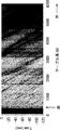
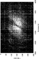
- the identification unit 30 uses DAS to acquire a Rayleigh scattered light pattern representing a change in water pressure generated at each point on the optical fiber 11 due to a change in water pressure due to an event occurring in the observation region. For example, when the backscattered light when a change in water pressure due to waves occurs in the observation region is processed, a pattern as shown in FIG. 2 can be obtained. Further, by processing the backscattered light when the water pressure changes due to the movement of the ship in the observation region, the patterns shown in FIGS. 4 to 7 can be obtained. These patterns represent changes in water pressure at each point on the optical fiber 11. Therefore, the specific unit 30 can detect the distribution of water pressure and the time variation of water pressure in the observation region based on these patterns. Furthermore, the identification unit 30 can identify an event that has occurred in the observation region based on the detection result.
- FIG. 2 shows the observation result of the water pressure change observed over 2 minutes using DAS in the observation range where the cable length of the optical fiber cable 10 from the receiving unit 20 is up to 6 km.
- the water depth 6km offshore is 120m, which is a shallow coast.
- the horizontal axis indicates the cable length [m] of the optical fiber cable 10 from the receiving unit 20, the left side is the beach, and the right side is offshore.
- the vertical axis indicates the time [sec], and the time becomes newer as it goes up.
- the shade of color indicates the level of water pressure felt by the cable, and the brighter the color, the higher the water pressure.
- the height of the water surface wave propagating in the observation range is represented by light and dark.
- the positive or negative slope of the line indicating the water surface wave indicates the direction of the water surface wave, and if the slope is negative, it indicates that the water surface wave is heading toward the beach. Further, the magnitude of the slope of the line indicating the water surface wave indicates the velocity of the water surface wave, and the larger the slope, the slower the velocity.
- FIG. 3 is a graph obtained by extracting the water pressure change at the point where the cable length is 2.6 km and the water depth is about 50 m in FIG. 2 (not at the same time).
- the horizontal axis represents time [sec] and the vertical axis represents the magnitude of water pressure. Therefore, FIG. 3 shows that the period of the water surface wave is about 10 seconds. Further, the wave height of the water surface wave can be estimated from the magnitude of the water pressure in FIG.
- the properties (traveling direction, velocity, wave height, period) of the water surface waves generated in the observation region can be understood.
- the properties of water surface waves when events such as tsunamis, waves, and tides occur are unique to those events. Therefore, by analyzing the properties of water surface waves generated in the observation area, it is possible to identify events such as tsunamis, waves, and tides that have occurred in the observation area.
- the identification unit 30 identifies the nature of the water surface wave based on the detection result of the water pressure distribution and the time fluctuation of the water pressure shown in FIG. 2, and further, based on the specific result, the event that occurred in the observation region. To identify tsunamis, waves, tides, etc.
- FIG. 8 shows a submarine cable attached to FIG. 2 that detects water surface waves at substantially the same location and at the same time using DVS. It can be seen that waves can be detected in the same way by either detection method.
- FIG. 4 shows the observation result of the water pressure change observed in the observation region where the cable length of the optical fiber cable 10 from the receiving unit 20 is from 10 km to 15 km using DAS for 6 minutes.
- FIGS. 5 to 7 show the observation results of the water pressure change observed over 6 minutes using DAS in the observation region where the cable length is 9 km to 14 km. Note that FIGS. 4 to 7 show the observation results in different time zones. Further, in FIGS. 4 to 7, the horizontal axis, the vertical axis, and the shade of color are the same as those in FIG.
- the identification unit 30 identifies the movement of the ship as an event occurring in the observation region based on the detection results of the water pressure distribution and the time variation of the water pressure shown in FIGS. 4 to 7.
- the Rayleigh scattered light includes a pattern caused by waves such as waves and a pattern caused by the movement of the ship. , May appear at the same time.
- the identification unit 30 erases one pattern, identifies the event based on the other pattern, and then erases the other pattern, and the event is based on one pattern. Should be specified.
- the specific unit 30 acquires a pattern of Rayleigh scattered light caused by a certain event, the specific unit 30 performs an FFT (Fast Fourier Transform) on the pattern at a frequency peculiar to the event, so that a more detailed pattern related to the event is obtained. Can be obtained.
- the identification unit 30 FFTs the Rayleigh scattered light pattern shown in FIGS. 2, 3 and 8 at a frequency specific to the wave to provide a more detailed pattern for the wave. Can be obtained. Therefore, the specific unit 30 can obtain more detailed information about the wave based on a more detailed pattern about the wave.
- a method of identifying an event occurring in the observation region by using DAS or DVS in the specific unit 30 has been described with reference to FIGS. 2 to 8, but these methods are examples. However, it is not limited to this. For example, pattern matching may be used, or a learning model that has been machine-learned (for example, deep learning) by supervised learning may be used to identify an event that has occurred in the observation region.
- pattern matching may be used, or a learning model that has been machine-learned (for example, deep learning) by supervised learning may be used to identify an event that has occurred in the observation region.
- the specific unit 30 holds in advance the pattern of Rayleigh scattered light when the event occurs for each event to be observed as a matching pattern.
- the specific unit 30 acquires the pattern of Rayleigh scattered light
- the specific unit 30 compares the acquired pattern of Rayleigh scattered light with the matching pattern.
- the specific unit 30 determines that an event corresponding to the matching pattern has occurred.
- the specific unit 30 when using a learning model by machine learning, the specific unit 30 inputs a plurality of sets of teacher data indicating a certain event and a pattern of Rayleigh scattered light when the event occurs, and inputs a learning model. Is built and held in advance. When the specific unit 30 acquires the pattern of Rayleigh scattered light, the specific unit 30 inputs the acquired pattern of Rayleigh scattered light to the learning model. As a result, the specific unit 30 obtains the event that occurred in the observation region as the output result of the learning model.
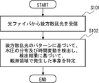
- the receiving unit 20 receives backscattered light from the optical fiber 11 constituting the optical fiber cable 10 arranged in the water area to be the observation region (step S101).
- the specific unit 30 detects the distribution of water pressure in the observation region and the time variation of water pressure based on the pattern of Rayleigh scattered light among the backscattered light, and based on the detection result, the event that occurred in the observation region. Is specified (step S102).
- the receiving unit 20 receives the backscattered light from the optical fiber 11 arranged in the water in the observation region.
- the identification unit 30 detects the distribution of water pressure in the observation region and the time variation of water pressure based on the pattern of Rayleigh scattered light among the backscattered light, and identifies the event occurring in the observation region based on the detection result. .. Therefore, various events can be observed, not limited to tsunamis, as events that occur in the water area to be observed.
- the second embodiment is an example in which the subsequent operation is added when a tsunami or a wave is specified as an event occurring in the observation region in the first embodiment described above.
- the configuration itself of the second embodiment is the same as that of the first embodiment described above.
- the specific unit 30 has the properties (traveling direction, velocity) of the water surface wave generated in the observation region from, for example, the detection result of the water pressure distribution and the time fluctuation of the water pressure in the observation region shown in FIGS. 2 and 8. , Wave height, period) can be specified. Therefore, when the event occurring in the observation area is a tsunami or a wave, the specific unit 30 can specify the nature of the tsunami or the wave.
- the specific unit 30 predicts the time when the tsunami or wave arrives or passes at the predetermined point and the wave height when the tsunami or wave arrives or passes at the predetermined point based on the nature of the tsunami or wave. To do.
- the point where the tsunami or wave arrives is the land point, and the point where the tsunami or wave passes is the water area.
- the specific unit 30 uses statistical data as statistical data on the correspondence between the nature of a tsunami or wave at a certain position at a certain time and the time and wave height when the tsunami or wave actually arrives or passes at a predetermined point. Keep it. Then, the specific unit 30 may make the above-mentioned prediction based on the statistical data.
- the specific unit 30 estimates the possibility of damage caused by the tsunami or wave to a predetermined point based on the nature of the tsunami or wave, and further estimates the level of damage when there is a possibility of causing damage. Is also good.
- the specific unit 30 determines the nature of the tsunami or wave at a certain position, the presence or absence of damage actually caused by the tsunami or wave to a predetermined land point and a predetermined water area, and the level of damage when there is damage. The correspondence between and is retained as statistical data. Then, the specific unit 30 may perform the above estimation based on the statistical data.
- the specific unit 30 may notify a predetermined notification destination of the above-mentioned prediction result and the above-mentioned estimation result.
- the predetermined notification destination may be the national government, local governments, fishermen, travel vessels, or the like.
- the predetermined notification destination may be a fisherman, a travel vessel, a work vehicle working in the water area, a surfer, an angler, or the like.
- the predetermined notification destination may be limited to the notification destination registered in the system to receive the notification in advance.
- steps S201 and S202 similar to steps S101 and S102 in FIG. 9 are performed.
- step S202 If the event identified in step S202 is a tsunami or wave (Yes in step S203), then the identification unit 30 arrives or passes the tsunami or wave at a predetermined point based on the nature of the tsunami or wave. Predict the time and the wave height when arriving or passing (step S204).
- the specific unit 30 estimates the possibility of damage caused by the tsunami or wave to a predetermined point based on the nature of the tsunami or wave, and further estimates the level of damage when there is a possibility of causing damage. Is also good. Further, the specific unit 30 may notify a predetermined notification destination of the above-mentioned prediction result and the above-mentioned estimation result.
- the specific unit 30 determines the time when the tsunami or wave arrives or passes at a predetermined point not only directly above the optical fiber cable 10, and the time when the tsunami or wave arrives or passes. Predict the wave height at that time. Therefore, it is possible not only to observe the tsunami or wave generated in the water area to be observed, but also to obtain the prediction result of the time when the tsunami or wave arrives or passes and the wave height at that time. Other effects are the same as those in the first embodiment described above.
- the third embodiment is an example in which the subsequent operation is added when the movement of the ship is specified as the event that occurred in the observation region in the first embodiment described above.
- the configuration itself of the third embodiment is the same as that of the first embodiment described above.
- the identification unit 30 can specify the number and position of ships moving in the observation area from, for example, the distribution of water pressure in the observation area shown in FIGS. 4 to 7 and the detection result of the time fluctuation of the water pressure.
- the traveling direction of the ship can be known from the direction of the gap between the two tow waves representing one ship.
- the speed of two tow waves representing one ship can be used to determine the speed of that ship. Therefore, the identification unit 30 determines the state (speed, traveling direction, position, number of vessels) of the ship moving in the observation area from the detection result of the water pressure distribution and the time variation of the water pressure in the observation area shown in FIGS. 4 to 7. Can be identified.
- the specific unit 30 detects that the ship has invaded a predetermined area or may invade a predetermined area based on the state of the ship.
- the predetermined area is, for example, a territorial waters, a fishing ground, or the like.
- the specific unit 30 may be able to wirelessly receive at least position data information indicating the position of a ship traveling in the sea. For example, from a ship equipped with an AIS (Automatic Identification System), position data information indicating the position, movement status, destination, etc. of the ship can be wirelessly received.
- the identification unit 30 may identify a ship that has invaded a predetermined area or a ship that may invade a predetermined area based on the position data information of the ship. For example, if the identification unit 30 has position data information indicating the same position as the position of the ship specified from the water pressure distribution in the observation region and the detection result of the time fluctuation of the water pressure, the specific unit 30 sets the ship indicated by the position data information in the area. Identify as an invading vessel or a vessel that may invade a given area.
- AIS Automatic Identification System
- the specific unit 30 may notify the predetermined notification destination of the detection result.
- the predetermined area is the territorial waters, the country can be considered as the predetermined notification destination.
- the predetermined area is a fishing ground, a fisherman working in the fishing ground can be considered as a predetermined notification destination.
- the predetermined notification destination may be limited to the notification destination registered in the system to receive the notification in advance.
- steps S301 and S302 similar to steps S101 and S102 in FIG. 9 are performed.
- step S302 When the event identified in step S302 is the movement of a ship (Yes in step S303), the identification unit 30 subsequently enters a predetermined area or a predetermined area based on the state of the ship. Detects that there is a possibility of invading the (step S304).
- the identification unit 30 identifies the ship that has invaded the area or the ship that may invade the predetermined area by using the position data information. You may. Further, when the specific unit 30 detects that the ship has invaded a predetermined area or may invade a predetermined area, the specific unit 30 may notify the predetermined notification destination of the detection result.
- the specific unit 30 detects that the ship has invaded a predetermined area or may invade a predetermined area based on the state of the ship. To do. Therefore, it is possible not only to observe that the ship is moving in the water area to be observed, but also to observe that the ship has invaded a predetermined area or may invade a predetermined area. can do. Other effects are the same as those in the first embodiment described above.
- the fourth embodiment is an example in which the subsequent operation is added when the tide is specified as the event that occurred in the observation region in the first embodiment described above.
- the configuration of the fourth embodiment is the same as that of the first embodiment described above.
- the specific unit 30 has the properties (traveling direction, velocity) of the water surface wave generated in the observation region from, for example, the detection result of the water pressure distribution and the time fluctuation of the water pressure in the observation region shown in FIGS. 2 and 8. , Wave height, period) can be specified.
- the identification unit 30 can identify that the event occurring in the observation region is a tide based on the period of the water surface wave.
- the tide may behave differently from the usual tide. For example, when a storm surge or a rapid tide occurs, it behaves differently from the usual tide. At this time, whether or not the behavior is different from the usual tide can be determined from the pattern of Rayleigh scattered light among the backscattered light generated at each point on the optical fiber 11.
- the specific unit 30 detects that a storm surge or a rapid tide is occurring based on the pattern of Rayleigh scattered light among the backscattered light generated at each point on the optical fiber 11. At this time, the specific unit 30 may detect that a storm surge or a rapid tide is occurring by using, for example, pattern matching.
- the specific unit 30 holds in advance the pattern of Rayleigh scattered light when a normal tide occurs as a matching pattern.
- the identification unit 30 identifies that the event occurring in the observation region is a tide, the identification unit 30 compares the Rayleigh scattered light pattern at that time with the matching pattern. If there is no matching pattern in which the matching rate with the Rayleigh scattered light pattern is equal to or greater than the threshold value, the specific unit 30 determines that a storm surge or a rapid tide has occurred.
- the specific unit 30 needs to analyze the pattern of Rayleigh scattered light caused by the tide in detail. Therefore, the specific unit 30 acquires a more detailed pattern regarding the tide by FFTing the pattern of Rayleigh scattered light caused by the tide at a frequency peculiar to the tide, and based on the detailed pattern, the storm surge or sudden It is good to detect the tide.
- the specific unit 30 may notify a predetermined notification destination of the detection result.
- the predetermined notification destination may be the national government, local governments, fishermen, travel vessels, surfers, anglers, and the like.
- the predetermined notification destination may be limited to the notification destination registered in the system to receive the notification in advance.
- steps S401 and S402 similar to steps S101 and S102 in FIG. 9 are performed.
- step S402 When the event identified in step S402 is a tide (Yes in step S403), the identification unit 30 is subsequently based on the Rayleigh scattered light pattern of the backscattered light generated at each point on the optical fiber 11. Then, it is detected that a high tide or a rapid tide is occurring (step S404). When the specific unit 30 detects that a storm surge or a rapid tide is occurring, the specific unit 30 may notify a predetermined notification destination of the detection result.
- the specific unit 30 generates a storm surge or a rapid tide based on the pattern of Rayleigh scattered light among the backscattered light generated at each point on the optical fiber 11. Detect that you are doing. Therefore, it is possible not only to observe the tide generated in the water area to be observed, but also to observe the occurrence of a storm surge or a rapid tide. Other effects are the same as those in the first embodiment described above.
- the configuration itself of the fifth embodiment is the same as that of the first to fourth embodiments described above.
- the Rayleigh scattered light pattern of the backscattered light fluctuates due to the change in water pressure due to the event occurring in the observation region, and the light is generated in the observation region. The event was identified.
- the specific unit 30 detects the water depth in the observation region based on the pattern of Rayleigh scattered light among the backscattered light generated at each point on the optical fiber 11.
- the specific unit 30 can also detect a change in the water depth in the observation area by detecting the water depth in the observation area periodically or irregularly. For example, in rivers and dams, when flooding occurs, the water depth becomes deeper. Therefore, the specific unit 30 may detect that the flood has occurred based on whether or not the water depth has become deeper in the river or dam.
- the specific unit 30 may detect that a crustal movement on the seabed has occurred based on whether or not the water depth has changed in the sea.
- the specific unit 30 may notify a predetermined notification destination of the detection result.
- the designated notification destination may be the national government, local governments, or the like.
- the predetermined notification destination may be limited to the notification destination registered in the system to receive the notification in advance.
- the specific unit 30 detects the water depth in the observation region based on the pattern of Rayleigh scattered light among the backscattered light generated at each point on the optical fiber 11. To do. Therefore, the water depth in the observation area can also be observed. In addition, from changes in water depth in the observation area, it is possible to observe flooding in rivers and dams and crustal movements on the seafloor in the sea. Other effects are the same as those in the first embodiment described above.
- the specific unit 30 sets the time difference between the time when the receiving unit 20 incidents the pulsed light on the optical fiber 11 and the time when the receiving unit 20 receives the backward scattered light from the optical fiber 11. Based on this, the position on the optical fiber 11 where the backward scattered light is generated (the cable length of the optical fiber cable 10 from the receiving unit 20) is specified. However, the correspondence between the position represented by the latitude / longitude coordinate system and the position on the optical fiber 11 is estimated from the laying route information and has an error.
- the receiving unit 20 and the specific unit 30 are temporarily connected to the optical fiber cable 10, and the optical fiber cable 10 is hit or touched to generate vibration or sound in the optical fiber cable 10, and the light at that time is generated.
- the position on the fiber 11 is specified.
- the correspondence between the specified position on the optical fiber 11 and the actual position can be calibrated because the GNSS (Global Navigation Satellite System) satellite radio wave can be received and accurately grasped.
- GNSS Global Navigation Satellite System
- the optical fiber cable 10 when laying one optical fiber cable 10, the optical fiber cable 10 may be partially laid in a shape such as a circle, a triangle, or a square. As a result, the optical fiber cable 10 is laid three-dimensionally, so that the water surface wave and the traveling direction of the ship can be specified with high accuracy.
- FIG. 13 shows an example in which the optical fiber cable 10 is partially laid in a round shape
- FIG. 14 shows an example in which the optical fiber cable 10 is partially laid in a triangular shape.
- the size of the partially laid shape of the optical fiber cable 10 is about half or less than the wavelength of the backscattered light to be detected.
- a plurality of optical fiber cables 10 may be laid so as to face different directions.
- the optical fiber cable 10 is laid three-dimensionally, so that the water surface wave and the traveling direction of the ship can be specified with high accuracy.
- FIG. 15 shows an example in which two optical fiber cables 10 are laid so as to face different directions from each other.
- the plurality of optical fiber cables 10 may or may not intersect each other.
- the receiving unit 20 and the specific unit 30 are shown in the drawings as independent components, but may be provided in one device (optical fiber sensing device). It may be distributed to a plurality of devices.
- the receiving unit 20 and the specific unit 30 can be provided in one device (optical fiber sensing device). Therefore, in the following, with reference to FIG. 16, the hardware configuration of the computer 40 that realizes the optical fiber sensing device including the receiving unit 20 and the specific unit 30 will be described.
- the computer 40 includes a processor 41, a memory 42, a storage 43, an input / output interface (input / output I / F) 44, a communication interface (communication I / F) 45, and the like.
- the processor 41, the memory 42, the storage 43, the input / output interface 44, and the communication interface 45 are connected by a data transmission line for transmitting and receiving data to and from each other.
- the processor 41 is, for example, an arithmetic processing unit such as a CPU (Central Processing Unit) or a GPU (Graphics Processing Unit).
- the memory 42 is, for example, a memory such as a RAM (Random Access Memory) or a ROM (Read Only Memory).
- the storage 43 is, for example, a storage device such as an HDD (Hard Disk Drive), an SSD (Solid State Drive), or a memory card. Further, the storage 43 may be a memory such as a RAM or a ROM.
- the storage 43 stores a program that realizes the functions of the components (reception unit 20 and specific unit 30) included in the optical fiber sensing device. By executing each of these programs, the processor 41 realizes the functions of the components included in the optical fiber sensing device. Here, when executing each of the above programs, the processor 41 may read these programs onto the memory 42 and then execute the programs, or may execute the programs without reading them onto the memory 42.
- the memory 42 and the storage 43 also play a role of storing information and data held by the components included in the optical fiber sensing device.
- Non-temporary computer-readable media include various types of tangible storage media.
- Examples of non-temporary computer-readable media include magnetic recording media (eg, flexible disks, magnetic tapes, hard disk drives), opto-magnetic recording media (eg, opto-magnetic discs), CD-ROMs (Compact Disc-ROMs), CDs. -R (CD-Recordable), CD-R / W (CD-ReWritable), semiconductor memory (for example, mask ROM, PROM (Programmable ROM), EPROM (Erasable PROM), flash ROM, RAM.
- the program also includes.
- the computer-readable medium can supply the program to the computer via a wired communication path such as an electric wire and an optical fiber, or a wireless communication path.
- the input / output interface 44 is connected to a display device 441, an input device 442, a sound output device 443, and the like.
- the display device 441 is a device that displays a screen corresponding to drawing data processed by the processor 41, such as an LCD (Liquid Crystal Display), a CRT (Cathode Ray Tube) display, and a monitor.
- the input device 442 is a device that receives an operator's operation input, and is, for example, a keyboard, a mouse, a touch sensor, and the like.
- the display device 441 and the input device 442 may be integrated and realized as a touch panel.
- the sound output device 443 is a device such as a speaker that acoustically outputs sound corresponding to acoustic data processed by the processor 41.
- the communication interface 45 transmits / receives data to / from an external device.
- the communication interface 45 communicates with an external device via a wired communication path or a wireless communication path.
- Appendix 1 An optical fiber that is placed underwater and detects changes in water pressure caused by events that occur in the observation area.
- a receiving unit that receives an optical signal from the optical fiber and Based on the pattern of the optical signal, the distribution of the water pressure in the observation region and the time variation of the water pressure are detected, and based on the detection result, a specific unit for identifying an event occurring in the observation region is provided.
- Fiber optic sensing system An optical fiber that is placed underwater and detects changes in water pressure caused by events that occur in the observation area.
- the specific part is When a tsunami or wave is identified as an event that occurred in the observation area, Based on the distribution of water pressure in the observation area and the detection result of the time fluctuation of water pressure, the nature of the tsunami or the wave is specified. Based on the nature of the tsunami or the wave, the time when the tsunami or the wave arrives or passes at a predetermined point and the wave height when the tsunami or the wave arrives or passes at the predetermined point are predicted. To do The optical fiber sensing system according to Appendix 1. (Appendix 3) The specific part is Notify the predetermined notification destination of the prediction result of the time when the tsunami or the wave arrives or passes at the predetermined point and the wave height when the tsunami or the wave arrives or passes at the predetermined point.
- the optical fiber sensing system according to Appendix 2. (Appendix 4) The specific part is Based on the nature of the tsunami or the wave, the possibility of damage caused by the tsunami or the wave to the predetermined point is estimated, and if there is a possibility of causing damage, the level of damage is further estimated.
- the optical fiber sensing system according to Appendix 2 or 3. (Appendix 5) The specific part is Notify the predetermined notification destination of the estimated result of the possibility of damage caused by the tsunami or the wave to the predetermined point and the level of damage when there is a possibility of causing damage.
- the specific part is When the movement of the ship is specified as an event that occurred in the observation area, Based on the distribution of water pressure in the observation area and the detection result of the time fluctuation of water pressure, the state of the ship is specified. Detecting that the ship has invaded or may have invaded a predetermined area based on the condition of the ship.
- the optical fiber sensing system according to Appendix 1. (Appendix 7)
- the specific part is The position data information of the ship is received wirelessly, Based on the position data information, the ship that has invaded the predetermined area or the ship that may invade the predetermined area is identified.
- the specific part is When it is detected that the ship has invaded a predetermined area or there is a possibility of invading the predetermined area, the detection result is notified to the predetermined notification destination.
- the optical fiber sensing system according to Appendix 6 or 7. (Appendix 9) The specific part is When the tide is identified as an event that occurred in the observation area, Detects that a storm surge or a rapid tide is occurring in the observation area based on the pattern of the optical signal.
- the optical fiber sensing system according to Appendix 1. (Appendix 10)
- the specific part is When it is detected that a storm surge or a rapid tide is occurring in the observation area, the detection result is notified to a predetermined notification destination.
- the specific part is The water depth in the observation region is detected based on the pattern of the optical signal.
- the optical fiber sensing system according to any one of Appendix 1 to 10.
- the specific part is By detecting the water depth in the observation area periodically or irregularly, the change in the water depth in the observation area is detected.
- the optical fiber sensing system according to Appendix 11. It is an event identification method using an optical fiber sensing system. A reception step that receives an optical signal from an optical fiber that is placed underwater and detects changes in water pressure caused by an event that occurs in the observation area.
- Event identification method Includes a specific step of detecting the distribution of water pressure and the time variation of water pressure in the observation region based on the pattern of the optical signal, and identifying an event occurring in the observation region based on the detection result.
- Event identification method (Appendix 14)
- the specific step When a tsunami or wave is identified as an event that occurred in the observation area, Based on the distribution of water pressure in the observation area and the detection result of the time fluctuation of water pressure, the nature of the tsunami or the wave is specified. Based on the nature of the tsunami or the wave, the time when the tsunami or the wave arrives or passes at a predetermined point and the wave height when the tsunami or the wave arrives or passes at the predetermined point are predicted. To do The event identification method according to Appendix 13.
- the event identification method according to Appendix 13. (Appendix 22) In the specific step, When it is detected that a storm surge or a rapid tide is occurring in the observation area, the detection result is notified to a predetermined notification destination. The event identification method according to Appendix 21. (Appendix 23) In the specific step, The water depth in the observation region is detected based on the pattern of the optical signal. The event identification method according to any one of Appendix 13 to 22. (Appendix 24) In the specific step, By detecting the water depth in the observation area periodically or irregularly, the change in the water depth in the observation area is detected. The event identification method according to Appendix 23.
Landscapes
- Physics & Mathematics (AREA)
- General Physics & Mathematics (AREA)
- Life Sciences & Earth Sciences (AREA)
- Remote Sensing (AREA)
- Engineering & Computer Science (AREA)
- Radar, Positioning & Navigation (AREA)
- Hydrology & Water Resources (AREA)
- Acoustics & Sound (AREA)
- Environmental & Geological Engineering (AREA)
- Geology (AREA)
- General Life Sciences & Earth Sciences (AREA)
- Geophysics (AREA)
- Geophysics And Detection Of Objects (AREA)
Priority Applications (2)
| Application Number | Priority Date | Filing Date | Title |
|---|---|---|---|
| JP2021552120A JPWO2021075145A1 (https=) | 2019-10-18 | 2020-08-20 | |
| US17/767,509 US20240085180A1 (en) | 2019-10-18 | 2020-08-20 | Optical fiber sensing system and event identification method |
Applications Claiming Priority (2)
| Application Number | Priority Date | Filing Date | Title |
|---|---|---|---|
| JP2019-191494 | 2019-10-18 | ||
| JP2019191494 | 2019-10-18 |
Publications (1)
| Publication Number | Publication Date |
|---|---|
| WO2021075145A1 true WO2021075145A1 (ja) | 2021-04-22 |
Family
ID=75537366
Family Applications (1)
| Application Number | Title | Priority Date | Filing Date |
|---|---|---|---|
| PCT/JP2020/031364 Ceased WO2021075145A1 (ja) | 2019-10-18 | 2020-08-20 | 光ファイバセンシングシステム及び事象特定方法 |
Country Status (3)
| Country | Link |
|---|---|
| US (1) | US20240085180A1 (https=) |
| JP (1) | JPWO2021075145A1 (https=) |
| WO (1) | WO2021075145A1 (https=) |
Cited By (2)
| Publication number | Priority date | Publication date | Assignee | Title |
|---|---|---|---|---|
| WO2023073804A1 (ja) * | 2021-10-26 | 2023-05-04 | 日本電気株式会社 | キャリブレーションシステム、キャリブレーション方法、及びコンピュータ可読媒体 |
| WO2024190020A1 (ja) * | 2023-03-16 | 2024-09-19 | 日本電気株式会社 | 物体侵入検出システム、その検出方法及びプログラム |
Families Citing this family (1)
| Publication number | Priority date | Publication date | Assignee | Title |
|---|---|---|---|---|
| JP7306562B2 (ja) * | 2020-02-28 | 2023-07-11 | 日本電信電話株式会社 | 浸水検知システム及び浸水検知方法 |
Citations (8)
| Publication number | Priority date | Publication date | Assignee | Title |
|---|---|---|---|---|
| JPH08128869A (ja) * | 1994-10-28 | 1996-05-21 | Nec Corp | 津波検出装置及び津波検出システム |
| JPH11248581A (ja) * | 1998-02-26 | 1999-09-17 | Natl Res Inst For Earth Science & Disaster Prevention | 光ファイバーを用いた水圧センサ |
| JP2004227045A (ja) * | 2003-01-20 | 2004-08-12 | Wham Net Service Co Ltd | 漁場侵入者監視システムおよび漁場侵入者監視方法 |
| JP2004251896A (ja) * | 2003-01-31 | 2004-09-09 | Universal Shipbuilding Corp | 船舶の航過検知装置、そのプログラム及びその方法 |
| JP2006170920A (ja) * | 2004-12-17 | 2006-06-29 | Nec Mobiling Ltd | 潮位監視システム,潮位監視システム用の海上ブイ及び地上局装置、潮位監視方法、潮位監視プログラム |
| CN101825499A (zh) * | 2010-05-18 | 2010-09-08 | 华北电力大学(保定) | 一种基于光纤布里渊散射原理的海水温度剖面测量方法 |
| JP2016008865A (ja) * | 2014-06-24 | 2016-01-18 | 株式会社 サヤ | 津波検知装置 |
| JP2017227501A (ja) * | 2016-06-21 | 2017-12-28 | 国立大学法人東北大学 | 津波浸水予測システム、データ処理サーバ、津波浸水予測の依頼方法及びプログラム |
Family Cites Families (9)
| Publication number | Priority date | Publication date | Assignee | Title |
|---|---|---|---|---|
| JPH076862B2 (ja) * | 1986-04-30 | 1995-01-30 | 日本電信電話株式会社 | 光フアイバ圧力センサ |
| JP2876528B1 (ja) * | 1998-01-14 | 1999-03-31 | 科学技術庁防災科学技術研究所長 | 圧力変化計測装置 |
| JP2004271326A (ja) * | 2003-03-07 | 2004-09-30 | Taisei Corp | 海底地盤挙動計測システム |
| JP5825810B2 (ja) * | 2010-03-30 | 2015-12-02 | 三菱スペース・ソフトウエア株式会社 | 津波被害予想装置及び津波被害予想プログラム及び記録媒体 |
| JP2012167950A (ja) * | 2011-02-10 | 2012-09-06 | Tokyo Electric Power Co Inc:The | 津波高さ算出方法、及び津波高さ算出装置 |
| JPWO2014083931A1 (ja) * | 2012-11-30 | 2017-01-05 | ニューブレクス株式会社 | 光ファイバ式圧力計 |
| JP6521777B2 (ja) * | 2014-10-22 | 2019-05-29 | 三菱電機株式会社 | 津波監視システム |
| GB201601060D0 (en) * | 2016-01-20 | 2016-03-02 | Fotech Solutions Ltd | Distributed optical fibre sensors |
| JP6902790B2 (ja) * | 2018-03-15 | 2021-07-14 | 国立研究開発法人防災科学技術研究所 | 津波予測システム |
-
2020
- 2020-08-20 JP JP2021552120A patent/JPWO2021075145A1/ja active Pending
- 2020-08-20 US US17/767,509 patent/US20240085180A1/en not_active Abandoned
- 2020-08-20 WO PCT/JP2020/031364 patent/WO2021075145A1/ja not_active Ceased
Patent Citations (8)
| Publication number | Priority date | Publication date | Assignee | Title |
|---|---|---|---|---|
| JPH08128869A (ja) * | 1994-10-28 | 1996-05-21 | Nec Corp | 津波検出装置及び津波検出システム |
| JPH11248581A (ja) * | 1998-02-26 | 1999-09-17 | Natl Res Inst For Earth Science & Disaster Prevention | 光ファイバーを用いた水圧センサ |
| JP2004227045A (ja) * | 2003-01-20 | 2004-08-12 | Wham Net Service Co Ltd | 漁場侵入者監視システムおよび漁場侵入者監視方法 |
| JP2004251896A (ja) * | 2003-01-31 | 2004-09-09 | Universal Shipbuilding Corp | 船舶の航過検知装置、そのプログラム及びその方法 |
| JP2006170920A (ja) * | 2004-12-17 | 2006-06-29 | Nec Mobiling Ltd | 潮位監視システム,潮位監視システム用の海上ブイ及び地上局装置、潮位監視方法、潮位監視プログラム |
| CN101825499A (zh) * | 2010-05-18 | 2010-09-08 | 华北电力大学(保定) | 一种基于光纤布里渊散射原理的海水温度剖面测量方法 |
| JP2016008865A (ja) * | 2014-06-24 | 2016-01-18 | 株式会社 サヤ | 津波検知装置 |
| JP2017227501A (ja) * | 2016-06-21 | 2017-12-28 | 国立大学法人東北大学 | 津波浸水予測システム、データ処理サーバ、津波浸水予測の依頼方法及びプログラム |
Cited By (3)
| Publication number | Priority date | Publication date | Assignee | Title |
|---|---|---|---|---|
| WO2023073804A1 (ja) * | 2021-10-26 | 2023-05-04 | 日本電気株式会社 | キャリブレーションシステム、キャリブレーション方法、及びコンピュータ可読媒体 |
| JP7626244B2 (ja) | 2021-10-26 | 2025-02-04 | 日本電気株式会社 | キャリブレーションシステム、キャリブレーション方法、及びプログラム |
| WO2024190020A1 (ja) * | 2023-03-16 | 2024-09-19 | 日本電気株式会社 | 物体侵入検出システム、その検出方法及びプログラム |
Also Published As
| Publication number | Publication date |
|---|---|
| US20240085180A1 (en) | 2024-03-14 |
| JPWO2021075145A1 (https=) | 2021-04-22 |
Similar Documents
| Publication | Publication Date | Title |
|---|---|---|
| US9612189B2 (en) | Integrity monitoring system and a method of monitoring integrity of a stationary structure | |
| US9778097B2 (en) | Location and monitoring of undersea cables | |
| JP7380885B2 (ja) | 保護監視システム、保護監視方法及び保護監視プログラム | |
| WO2021075145A1 (ja) | 光ファイバセンシングシステム及び事象特定方法 | |
| JP7439935B2 (ja) | 水中騒音監視装置及び水中騒音処理方法 | |
| KR101740157B1 (ko) | 소노부이의 최적운용 위치 및 수심 결정 방법 | |
| CN104199123A (zh) | 海底电缆铺设质量检测系统 | |
| JP2026510815A (ja) | 海底ケーブルの露出の監視 | |
| JP2009229432A (ja) | Gps受信体を利用した津波観測システム | |
| JP6241995B2 (ja) | 潜水士情報取得方法および潜水士情報取得システム | |
| CN109895955A (zh) | 一种防渔船破坏的海洋潜标系统及其布设方法 | |
| Abadi et al. | Estimating the location of baleen whale calls using dual streamers to support mitigation procedures in seismic reflection surveys | |
| JP7255700B2 (ja) | 水圧センシングシステム並びに感度補正方法 | |
| CN117975667A (zh) | 基于分布式振动感知的风暴潮及海啸监测预警系统及方法 | |
| JP7532308B2 (ja) | 水中音場計測システム及び水中音場計測方法 | |
| CN111735437A (zh) | 一种基于Jason-1和CryoSat-2卫星数据的海底地貌解译方法 | |
| JP2025022243A (ja) | 干渉エリア情報出力装置、干渉エリア情報出力システム、干渉エリア情報出力方法および干渉エリア情報出力プログラム | |
| KR20160057241A (ko) | 연안해역 실시간 이상현상 관측방법 | |
| KR102899154B1 (ko) | 해황 융합 수로 정보 제공 방법 및 시스템 | |
| CN120083925B (zh) | 海底管道内外检测方法、控制器及检测装置 | |
| JP2006209712A (ja) | 津波検知装置 | |
| JP2025183780A (ja) | 敷設位置推定装置、敷設位置推定システム、敷設位置推定方法、及びプログラム | |
| CN114216555A (zh) | 基于分布式光纤振动传感的滩涂怪潮监测及预警方法 | |
| CN119103989A (zh) | 一种基于光纤动应变传感的堤坝河床冲刷监测系统及方法 | |
| CN119471704A (zh) | 一种海缆声光监测系统及海缆监测方法 |
Legal Events
| Date | Code | Title | Description |
|---|---|---|---|
| 121 | Ep: the epo has been informed by wipo that ep was designated in this application |
Ref document number: 20876583 Country of ref document: EP Kind code of ref document: A1 |
|
| ENP | Entry into the national phase |
Ref document number: 2021552120 Country of ref document: JP Kind code of ref document: A |
|
| WWE | Wipo information: entry into national phase |
Ref document number: 17767509 Country of ref document: US |
|
| NENP | Non-entry into the national phase |
Ref country code: DE |
|
| 122 | Ep: pct application non-entry in european phase |
Ref document number: 20876583 Country of ref document: EP Kind code of ref document: A1 |