WO2021070463A1 - 過給機 - Google Patents
過給機 Download PDFInfo
- Publication number
- WO2021070463A1 WO2021070463A1 PCT/JP2020/030464 JP2020030464W WO2021070463A1 WO 2021070463 A1 WO2021070463 A1 WO 2021070463A1 JP 2020030464 W JP2020030464 W JP 2020030464W WO 2021070463 A1 WO2021070463 A1 WO 2021070463A1
- Authority
- WO
- WIPO (PCT)
- Prior art keywords
- hinge portion
- joint member
- straight line
- center
- virtual straight
- Prior art date
Links
Images


Classifications
-
- F—MECHANICAL ENGINEERING; LIGHTING; HEATING; WEAPONS; BLASTING
- F02—COMBUSTION ENGINES; HOT-GAS OR COMBUSTION-PRODUCT ENGINE PLANTS
- F02B—INTERNAL-COMBUSTION PISTON ENGINES; COMBUSTION ENGINES IN GENERAL
- F02B37/00—Engines characterised by provision of pumps driven at least for part of the time by exhaust
- F02B37/12—Control of the pumps
- F02B37/18—Control of the pumps by bypassing exhaust from the inlet to the outlet of turbine or to the atmosphere
- F02B37/183—Arrangements of bypass valves or actuators therefor
- F02B37/186—Arrangements of actuators or linkage for bypass valves
-
- F—MECHANICAL ENGINEERING; LIGHTING; HEATING; WEAPONS; BLASTING
- F02—COMBUSTION ENGINES; HOT-GAS OR COMBUSTION-PRODUCT ENGINE PLANTS
- F02B—INTERNAL-COMBUSTION PISTON ENGINES; COMBUSTION ENGINES IN GENERAL
- F02B37/00—Engines characterised by provision of pumps driven at least for part of the time by exhaust
- F02B37/12—Control of the pumps
- F02B37/18—Control of the pumps by bypassing exhaust from the inlet to the outlet of turbine or to the atmosphere
- F02B37/183—Arrangements of bypass valves or actuators therefor
-
- Y—GENERAL TAGGING OF NEW TECHNOLOGICAL DEVELOPMENTS; GENERAL TAGGING OF CROSS-SECTIONAL TECHNOLOGIES SPANNING OVER SEVERAL SECTIONS OF THE IPC; TECHNICAL SUBJECTS COVERED BY FORMER USPC CROSS-REFERENCE ART COLLECTIONS [XRACs] AND DIGESTS
- Y02—TECHNOLOGIES OR APPLICATIONS FOR MITIGATION OR ADAPTATION AGAINST CLIMATE CHANGE
- Y02T—CLIMATE CHANGE MITIGATION TECHNOLOGIES RELATED TO TRANSPORTATION
- Y02T10/00—Road transport of goods or passengers
- Y02T10/10—Internal combustion engine [ICE] based vehicles
- Y02T10/12—Improving ICE efficiencies
Definitions
- This disclosure relates to a turbocharger.
- the turbocharger described in Patent Document 1 below is known.
- a bypass flow path that directly connects the exhaust gas inlet and the exhaust gas outlet to the turbine, a waist gate valve that opens and closes the bypass flow path, and a waist gate valve. It has.
- the wastegate valve is opened and a part of the exhaust gas supplied to the turbine is discharged through the bypass flow path.
- This turbocharger is equipped with an operation mechanism for opening and closing the waist gate valve. In the operation mechanism, when the rod of the actuator is moved forward and backward, the lever hinged to the tip of the rod swings, the rotation shaft of the valve body rotates, and the waist gate valve opens and closes.
- Patent No. 5845650 Japanese Unexamined Patent Publication No. 2003-148155 Japanese Unexamined Patent Publication No. 2012-132554 Japanese Unexamined Patent Publication No. 2013-210101
- the valve body receives the fluid force of the exhaust gas, and the force caused by this fluid force acts on the lever and rod of the operation mechanism.
- the fastening portion to which the operating mechanism is assembled may loosen or shift in position. Then, the operation control may become unstable due to looseness or misalignment of the fastening portion.
- the present disclosure describes a turbocharger that ensures the stability of operation control of moving parts.
- the supercharger includes an operation mechanism that swings an operation lever to operate a movable part by receiving a predetermined driving force
- the operation mechanism includes a driving member that reciprocates by the driving force and a driving member.
- a joint member that is fastened to the driving member with a fastening material and reciprocates together with the driving member is connected to the joint member via the first hinge portion and is coupled to the operation lever via the second hinge portion. It has a link plate, and the rotation center of the first hinge portion reciprocates on a predetermined virtual straight line with the reciprocating movement of the joint member, and the swing center of the operation lever and the rotation center of the second hinge portion Is shorter than the distance between the swing center and the virtual straight line.
- the stability of operation control of moving parts can be ensured.
- the supercharger includes an operation mechanism that swings an operation lever to operate a movable part by receiving a predetermined driving force
- the operation mechanism includes a driving member that reciprocates by the driving force and a driving member.
- a joint member that is fastened to the driving member with a fastening material and reciprocates together with the driving member is connected to the joint member via the first hinge portion and is coupled to the operation lever via the second hinge portion. It has a link plate, and the rotation center of the first hinge portion reciprocates on a predetermined virtual straight line with the reciprocating movement of the joint member, and the swing center of the operation lever and the rotation center of the second hinge portion Is shorter than the distance between the swing center and the virtual straight line.
- the moving part may be a part that adjusts the flow rate of the turbine by operation.
- the movable part may be a valve body of a waist gate valve that is opened and closed by swinging the operating lever.
- the supercharger of the present disclosure may further include an electric actuator that generates a driving force.
- the swing range of the operation lever by the operation mechanism is such that the rotation center of the second hinge portion is located on the perpendicular line drawn from the swing center to a virtual straight line, and the rotation center of the second hinge portion is the first hinge portion.
- the range may be up to a posture in which a predetermined amount is moved in the opposite direction to the above.
- FIG. 1 is a cross-sectional view of the supercharger 1 including the rotation axis H.
- the supercharger 1 is applied to, for example, an internal combustion engine of a ship or a vehicle.
- the supercharger 1 includes a turbine 2 and a compressor 3.
- the turbine 2 includes a turbine housing 4 and a turbine impeller 6 housed in the turbine housing 4.
- the turbine housing 4 has a scroll flow path 16 extending in the circumferential direction around the turbine impeller 6.
- the compressor 3 includes a compressor housing 5 and a compressor impeller 7 housed in the compressor housing 5.
- the compressor housing 5 has a scroll flow path 17 extending in the circumferential direction around the compressor impeller 7.
- the turbine impeller 6 is provided at one end of the rotating shaft 14, and the compressor impeller 7 is provided at the other end of the rotating shaft 14.
- a bearing housing 13 is provided between the turbine housing 4 and the compressor housing 5.
- the rotating shaft 14 is rotatably supported by the bearing housing 13 via a bearing 15, and the rotating shaft 14, the turbine impeller 6 and the compressor impeller 7 rotate around the rotating axis H as an integral rotating body 12.
- the turbine housing 4 is provided with an exhaust gas inflow port 8 and an exhaust gas outflow port 10.
- Exhaust gas discharged from an internal combustion engine flows into the turbine housing 4 through the exhaust gas inflow port 8 and flows into the turbine impeller 6 through the scroll flow path 16 to rotate the turbine impeller 6. After that, the exhaust gas flows out of the turbine housing 4 through the exhaust gas outlet 10.
- the compressor housing 5 is provided with a suction port 9 and a discharge port 11.
- the compressor impeller 7 rotates via the rotating shaft 14.
- the rotating compressor impeller 7 sucks in external air through the suction port 9. This air passes through the compressor impeller 7 and the scroll flow path 17, is compressed, and is discharged from the discharge port 11.
- the compressed air discharged from the discharge port 11 is supplied to the internal combustion engine described above.
- the supercharger 1 includes a bypass flow path 31 and a wastegate valve 33.
- the bypass flow path 31 directly connects the exhaust gas inflow port 8 of the turbine 2 and the exhaust gas outflow port 10.
- the wastegate valve 33 opens and closes the bypass flow path 31. By adjusting the opening degree of the wastegate valve 33, the amount of exhaust gas bypassing the turbine 2 is adjusted, and the flow rate of the turbine 2 is adjusted. Then, the pressure of the compressed air supplied to the internal combustion engine is adjusted by adjusting the flow rate of the turbine 2.
- the supercharger 1 includes an operation mechanism 35 for opening / closing the wastegate valve 33.
- the operation mechanism 35 includes an electric actuator 37, a joint member 39, a link plate 41, and an operation lever 43.
- the X, Y, and Z directions orthogonal to each other are defined and used for explanation.
- the + X direction is the front and the -X direction is the rear.
- the + Y direction is upward and the -Y direction is downward.
- the operating lever 43 includes a rotation shaft 57 of the valve body 55 of the wastegate valve 33.
- the rotating shaft 57 is provided at the upper end of the operating lever 43, penetrates the turbine housing 4, and is connected to the valve body 55.
- the operating lever 43, the rotating shaft 57, and the valve body 55 can swing in the XY plane around the swing center 59 relative to the turbine housing 4.
- the swing center 59 is also the center of the rotation shaft 57.
- the electric actuator 37 is a drive source that generates a driving force for swinging the operating lever 43.
- the electric actuator 37 has, for example, a main body portion 37a fixed to the turbine housing 4 and a rod 37b (driving member).
- the rod 37b extends in the + X direction from the main body 37a and expands and contracts in the ⁇ X direction with respect to the main body 37a.
- the front end of the rod 37b is threaded, and nuts 45 and 47 (fasteners) are screwed into it.
- a flat plate portion 39a orthogonal to the X direction is formed at the rear end portion of the joint member 39, and a bolt hole 39b penetrating in the X direction is formed in the flat plate portion 39a.
- the front end portion of the rod 37b is inserted into the bolt hole 39b of the flat plate portion 39a while being sandwiched between the two nuts 45 and 47 in the front-rear direction.
- the joint member 39 is fastened and fixed to the front end portion of the rod 37b.
- the X position of the joint member 39 with respect to the rod 37b can be adjusted by adjusting the screwing positions of the nuts 45 and 47 with respect to the rod 37b.
- the rear end portion of the link plate 41 is connected to the front end portion of the joint member 39 via the first hinge portion 51.
- the link plate 41 is rotatable in the XY plane around the rotation center 51a of the first hinge portion 51 relative to the joint member 39.
- the front end portion of the link plate 41 is coupled to the lower end portion of the operating lever 43 via the second hinge portion 52.
- the link plate 41 is rotatable in the XY plane around the rotation center 52a of the second hinge portion 52 relative to the operating lever 43.
- the state shown by the solid line in FIG. 3 indicates the state in which the wastegate valve 33 is fully closed (hereinafter, simply referred to as “fully closed state”). That is, in the fully closed state, the rotation center 52a is located on the perpendicular line T drawn from the swing center 59 to the virtual straight line L.
- the rotation center 52a moves in the + X direction, and the operating lever 43 rotates counterclockwise in FIG.
- the wastegate valve 33 is fully open (hereinafter, simply referred to as “fully open state”) when the rotation center 52a is moved by a predetermined amount in the + X direction.
- the swing range of the operation lever 43 by the operation mechanism 35 is such that the rotation center 52a is located from the posture in which the rotation center 52a is located on the perpendicular line T drawn from the swing center 59 to the virtual straight line L (corresponding to the fully closed state).
- the range is up to a posture (corresponding to a fully open state) in which a predetermined amount is moved in the direction opposite to that of the first hinge portion 51. That is, the movement range of the rotation center 52a by the operation mechanism 35 is only the region in front of the perpendicular line T drawn from the swing center 59 to the virtual straight line L.
- the distance between the swing center 59 of the operation lever 43 and the rotation center 52a of the second hinge portion 52 is shorter than the distance between the swing center 59 and the virtual straight line L.
- the rotation center 52a does not move to a region below the virtual straight line L.
- the straight line connecting the rotation center 51a and the rotation center 52a is inclined with respect to the virtual straight line L.
- the distance between the swing center 59 of the operation lever 43 and the rotation center 52a of the second hinge portion 52 is set to be equal to the distance between the swing center 59 and the virtual straight line L.
- the straight line connecting the rotation center 51a and the rotation center 52a and the straight line connecting the swing center 59 and the rotation center 52a are orthogonal to each other.
- the operation mechanism in the state shown in FIG. 5 is hereinafter referred to as an operation mechanism 135.
- the distance between the swing center 59 of the operation lever 43 and the rotation center 52a of the second hinge portion 52 is longer than the distance between the swing center 59 and the virtual straight line L.
- the rotation center 52a is located below the virtual straight line L as shown in FIG. 5, but in the fully open state, the rotation center 52a is above the virtual straight line L as shown in FIG. Will be located in. That is, the rotation center 52a of the operation mechanism 135 moves upward or downward from the virtual straight line L depending on the opening / closing operation of the wastegate valve 33.
- the valve body 55 of the wastegate valve 33 receives the fluid force of the exhaust gas.
- This fluid force is a force that rotates the operating lever 43 counterclockwise in FIGS. 5 and 6.
- the force caused by the fluid force pulls the joint member 39 toward the second hinge portion 52 side via the link plate 41, that is, acts on the joint member 39 as a force F indicated by an arrow in the drawing.
- the rotation center 52a is located above the virtual straight line L (see FIG. 6)
- the Y-direction component of the force F is upward, and when the rotation center 52a is located below the virtual straight line L (see FIG. 5). ),
- the Y-direction component of the force F is downward.
- the rotation center 52a moves upward or downward from the virtual straight line L, so that the joint member 39 during operation is provided with the joint member 39 during operation.
- the force having an upward component and the force having a downward component act alternately.
- the fixed position of the joint member 39 with respect to the rod 37b may be displaced vertically. That is, the joint member 39 may be displaced up and down with respect to the rod 37b by sliding up and down against the fastening force of the nuts 45 and 47 by the clearance between the rod 37b and the bolt hole 39b.
- the supercharger 1 employs an electric actuator 37 to control the opening degree of the wastegate valve 33 with high accuracy, it is easily affected by the slight displacement of the joint member 39 as described above. .. Further, there is also a problem that the nuts 45 and 47 are loosened by the above-mentioned force having an upward component and the force having a downward component acting alternately on the joint member 39.
- the rotation center 52a in the fully closed state is set to be located above the virtual straight line L in advance. Therefore, it is unlikely that the operation mechanism 135 will be in the state due to the tolerance of the parts, and the above-mentioned problem can be avoided. Therefore, the stability of the opening / closing control of the wastegate valve 33 is ensured.
- the joint member 39 may be assembled in advance so that the lower edge of the bolt hole 39b of the joint member 39 hits the rod 37b.
- the operation mechanism 35 for opening and closing the wastegate valve 33 has been described as an example, but the configuration of the above-mentioned operation mechanism 35 is also applied to the operation mechanism of other moving parts of the supercharger 1. Can be done.
- the other movable component of the turbocharger 1 may be, for example, an operation mechanism for rotating the nozzle of the variable nozzle mechanism.
Landscapes
- Engineering & Computer Science (AREA)
- Chemical & Material Sciences (AREA)
- Combustion & Propulsion (AREA)
- Mechanical Engineering (AREA)
- General Engineering & Computer Science (AREA)
- Supercharger (AREA)
Abstract
過給機は、操作レバーを揺動させウエストゲートバルブの弁体の操作を行う操作機構を備える。操作機構は、電動アクチュエータの往復動するロッドと、ロッドに対してナットで締結されロッドと一緒に往復動するジョイント部材と、ジョイント部材の往復動に伴って所定の仮想直線上を往復動する回転中心をもつ第1ヒンジ部を介してジョイント部材に結合されると共に、第2ヒンジ部を介して操作レバーに結合されたリンク板と、を有し、操作レバーの揺動中心と第2ヒンジ部の回転中心との距離が、揺動中心と仮想直線との距離よりも短い。
Description
本開示は過給機に関する。
従来、下記特許文献1に記載の過給機が知られている。この過給機は、内燃機関に供給する空気の圧力を制御するために、タービンへの排ガス入口と排ガス出口とを直接接続するバイパス流路と、上記バイパス流路を開閉するウエストゲートバルブと、を備えている。内燃機関に供給される空気の圧力が所定値を超えたときには、ウエストゲートバルブが開かれ、タービンに供給される排ガスの一部がバイパス流路を通じて排出される。この過給機は、ウエストゲートバルブの開閉操作のための操作機構を備えている。操作機構において、アクチュエータのロッドが進退されると、ロッド先端にヒンジ結合されたレバーが揺動して弁体の回動軸が回動し、ウエストゲートバルブが開閉動作する。
このウエストゲートバルブでは、弁体が排ガスの流体力を受け、この流体力に起因する力が操作機構のレバーやロッドに作用することになる。このウエストゲートバルブの例のように、過給機の可動部品を操作する操作機構に対して力が繰返し作用すると、操作機構を組付ける締結部分が緩んだり位置ずれしたりするといった虞がある。そして、締結部分の緩みや位置ずれによって、操作制御が不安定になる虞がある。上記のような課題に鑑み、本開示は、可動部品の操作制御の安定性を確保する過給機を説明する。
本開示の一態様に係る過給機は、所定の駆動力を受けて操作レバーを揺動させ可動部品の操作を行う操作機構を備え、操作機構は、駆動力によって往復動する原動部材と、原動部材に対して締結材で締結され原動部材と一緒に往復動するジョイント部材と、第1ヒンジ部を介してジョイント部材に結合されると共に、第2ヒンジ部を介して操作レバーに結合されたリンク板と、を有し、第1ヒンジ部の回転中心は、ジョイント部材の往復動に伴って所定の仮想直線上を往復動し、操作レバーの揺動中心と第2ヒンジ部の回転中心との距離が、揺動中心と仮想直線との距離よりも短い。
本開示の過給機によれば、可動部品の操作制御の安定性を確保することができる。
本開示の一態様に係る過給機は、所定の駆動力を受けて操作レバーを揺動させ可動部品の操作を行う操作機構を備え、操作機構は、駆動力によって往復動する原動部材と、原動部材に対して締結材で締結され原動部材と一緒に往復動するジョイント部材と、第1ヒンジ部を介してジョイント部材に結合されると共に、第2ヒンジ部を介して操作レバーに結合されたリンク板と、を有し、第1ヒンジ部の回転中心は、ジョイント部材の往復動に伴って所定の仮想直線上を往復動し、操作レバーの揺動中心と第2ヒンジ部の回転中心との距離が、揺動中心と仮想直線との距離よりも短い。
可動部品は、動作によってタービンの流量を調整する部品であってもよい。また、可動部品は、操作レバーの揺動によって開閉されるウエストゲートバルブの弁体であってもよい。本開示の過給機は、駆動力を発生する電動アクチュエータを更に備えることとしてもよい。
また、操作機構による操作レバーの揺動範囲は、揺動中心から仮想直線に下ろした垂線上に第2ヒンジ部の回転中心が位置する姿勢から、第2ヒンジ部の回転中心が第1ヒンジ部とは反対の方向に所定量移動した姿勢まで、の範囲であることとしてもよい。
以下、図面を参照しつつ本開示の実施形態について詳細に説明する。図1は、過給機1の回転軸線Hを含む断面を取った断面図である。過給機1は、例えば、船舶や車両の内燃機関に適用されるものである。
図1に示されるように、過給機1は、タービン2とコンプレッサ3とを備えている。タービン2は、タービンハウジング4と、タービンハウジング4に収納されたタービン翼車6と、を備えている。タービンハウジング4は、タービン翼車6の周囲において周方向に延びるスクロール流路16を有している。コンプレッサ3は、コンプレッサハウジング5と、コンプレッサハウジング5に収納されたコンプレッサ翼車7と、を備えている。コンプレッサハウジング5は、コンプレッサ翼車7の周囲において周方向に延びるスクロール流路17を有している。
タービン翼車6は回転軸14の一端に設けられており、コンプレッサ翼車7は回転軸14の他端に設けられている。タービンハウジング4とコンプレッサハウジング5との間には、軸受ハウジング13が設けられている。回転軸14は、軸受15を介して軸受ハウジング13に回転可能に支持されており、回転軸14、タービン翼車6及びコンプレッサ翼車7が一体の回転体12として回転軸線H周りに回転する。
タービンハウジング4には、排気ガス流入口8及び排気ガス流出口10が設けられている。内燃機関(図示せず)から排出された排気ガスが、排気ガス流入口8を通じてタービンハウジング4内に流入し、スクロール流路16を通じてタービン翼車6に流入し、タービン翼車6を回転させる。その後、排気ガスは、排気ガス流出口10を通じてタービンハウジング4外に流出する。
コンプレッサハウジング5には、吸入口9及び吐出口11が設けられている。上記のようにタービン翼車6が回転すると、回転軸14を介してコンプレッサ翼車7が回転する。回転するコンプレッサ翼車7は、吸入口9を通じて外部の空気を吸入する。この空気が、コンプレッサ翼車7及びスクロール流路17を通過して圧縮され吐出口11から吐出される。吐出口11から吐出された圧縮空気は、前述の内燃機関に供給される。
図2に示されるように、過給機1は、バイパス流路31とウエストゲートバルブ33とを備えている。バイパス流路31は、タービン2の排気ガス流入口8と排気ガス流出口10とを直接接続する。ウエストゲートバルブ33は、上記バイパス流路31を開閉する。ウエストゲートバルブ33の開度調整によって、タービン2をバイパスする排ガスの量が調整され、タービン2の流量が調整される。そして、タービン2の流量調整によって、内燃機関に供給される圧縮空気の圧力が調整される。
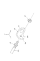
図3に示されるように、過給機1は、ウエストゲートバルブ33の開閉操作のための操作機構35を備えている。操作機構35は、電動アクチュエータ37と、ジョイント部材39と、リンク板41と、操作レバー43と、を備えている。以下では、各図に示されるように互いに直交するX、Y、及びZ方向を定め説明に用いる。また、「前」、「後」等の語を用いる場合には、+X方向を前方とし、-X方向を後方とする。また、「上」、「下」等の語を用いる場合には、+Y方向を上方とし、-Y方向を下方とする。以下では、XY平面に投影した状態の、操作機構35の各部品の位置関係及び動作について説明する。
操作レバー43は、ウエストゲートバルブ33の弁体55の回動軸57を含んでいる。回動軸57は、操作レバー43の上端部に設けられており、タービンハウジング4を貫通して弁体55に連結されている。操作レバー43、回動軸57及び弁体55は、タービンハウジング4に対して相対的に、揺動中心59の周りに、XY平面内で揺動可能である。揺動中心59は回動軸57の中心でもある。上記のように操作レバー43が揺動中心59周りに回動することで、弁体55が回動し、ウエストゲートバルブ33が開閉する。
電動アクチュエータ37は、操作レバー43の揺動のための駆動力を発生する駆動源である。電動アクチュエータ37は、例えばタービンハウジング4に固定される本体部37aとロッド37b(原動部材)とを有している。ロッド37bは、本体部37aから+X方向に延びており、本体部37aに対して±X方向に伸縮する。
図4に示されるように、ロッド37bの前端部にはネジが切られており、ナット45,47(締結材)が螺着される。ジョイント部材39の後端部にはX方向に直交する平板状の平板部39aが形成され、平板部39aにはX方向に貫通するボルト穴39bが形成されている。2つのナット45,47に前後に挟まれた状態で平板部39aのボルト穴39bにロッド37bの前端部が挿通されている。この状態でナット45,47が締め付けられることで、ジョイント部材39が、ロッド37bの前端部に対して締結され固定される。また、ロッド37bに対するナット45,47の螺着位置を調整することにより、ロッド37bに対するジョイント部材39のX位置を調整することができる。
図3に示されるように、ジョイント部材39の前端部には、第1ヒンジ部51を介してリンク板41の後端部が結合されている。リンク板41は、ジョイント部材39に対して相対的に、第1ヒンジ部51の回転中心51aの周りに、XY平面内で回転可能である。リンク板41の前端部は、第2ヒンジ部52を介して操作レバー43の下端部に結合されている。リンク板41は、操作レバー43に対して相対的に、第2ヒンジ部52の回転中心52aの周りに、XY平面内で回転可能である。
以上のような構造の操作機構35においては、電動アクチュエータ37に駆動電力が供給され、電動アクチュエータ37の駆動力でロッド37bがX方向に伸縮し、ジョイント部材39がX方向に往復動する。このとき、第1ヒンジ部51の回転中心51aは、X方向に平行な仮想直線L上で往復動する。なお、仮想直線Lはロッド37bの軸にも一致する。上記のジョイント部材39の往復動により、リンク板41を介して駆動力が操作レバー43の下端部の第2ヒンジ部52に伝達され、その結果、操作レバー43が揺動中心59の周りに揺動する。これにより、弁体55が回動し、ウエストゲートバルブ33が開閉する。
図3に実線で示される状態は、ウエストゲートバルブ33が全閉である状態(以下、単に「全閉状態」という)を示している。すなわち、全閉状態においては、揺動中心59から仮想直線Lに下ろした垂線T上に回転中心52aが位置する。このような操作レバー43の姿勢から、電動アクチュエータ37のロッド37bが+X方向に伸長されると、回転中心52aが+X方向に移動し、操作レバー43は図3における反時計回りに回動する。そして、図3に二点鎖線で示されるように、回転中心52aが+X方向に所定量移動した状態において、ウエストゲートバルブ33が全開である状態(以下、単に「全開状態」という)となる。
すなわち、操作機構35による操作レバー43の揺動範囲は、揺動中心59から仮想直線Lに下ろした垂線T上に回転中心52aが位置する姿勢(全閉状態に対応)から、回転中心52aが第1ヒンジ部51とは反対の方向に所定量移動した姿勢(全開状態に対応)まで、の範囲である。すなわち、操作機構35による回転中心52aの移動範囲は、揺動中心59から仮想直線Lに下ろした垂線Tよりも前方の領域のみである。
また、操作機構35では、操作レバー43の揺動中心59と第2ヒンジ部52の回転中心52aとの距離は、揺動中心59と仮想直線Lとの距離よりも短い。この構成により、回転中心52aは、仮想直線Lよりも下方の領域に移動することはない。全閉状態においては、回転中心51aと回転中心52aとを結ぶ直線は仮想直線Lに対して傾いている。
以上説明した操作機構35を備える過給機1の作用効果について説明する。まずは、操作機構35に対する比較例として、仮に、操作レバー43の揺動中心59と第2ヒンジ部52の回転中心52aとの距離を、揺動中心59と仮想直線Lとの距離と等しく設定した場合を考える。この設定では、全閉状態において、回転中心51aと回転中心52aとを結ぶ直線と、揺動中心59と回転中心52aとを結ぶ直線と、が直交することになる。
しかしながら、この設定によれば、部品の公差により、例えば操作レバー43の寸法がやや大きい場合などの要因で、図5に示される状態になる可能性がある。この図5に示される状態の操作機構を、以下では操作機構135と呼ぶ。操作機構135では、操作レバー43の揺動中心59と第2ヒンジ部52の回転中心52aとの距離は、揺動中心59と仮想直線Lとの距離よりも長い。そして、全閉状態においては図5に示されるように回転中心52aが仮想直線Lよりも下方に位置するが、全開状態においては図6に示されるように回転中心52aが仮想直線Lよりも上方に位置することになる。すなわち、操作機構135の回転中心52aは、ウエストゲートバルブ33の開閉動作によって、仮想直線Lよりも上方に行ったり下方に行ったりする。
ところで、ウエストゲートバルブ33の弁体55は排ガスの流体力を受ける。この流体力は、操作レバー43を図5及び図6における反時計回りに回転させる力である。そして、上記流体力に起因する力は、リンク板41を介してジョイント部材39を第2ヒンジ部52側に引っ張り、すなわち図中の矢印で示す力Fとしてジョイント部材39に作用する。回転中心52aが仮想直線Lよりも上方に位置するとき(図6参照)には力FのY方向成分は上向きであり、回転中心52aが仮想直線Lよりも下方に位置するとき(図5参照)には力FのY方向成分は下向きである。
図5及び図6に示されるように、操作機構135では、前述したとおり、回転中心52aが仮想直線Lよりも上方に行ったり下方に行ったりすることから、運転中のジョイント部材39には、上向き成分をもつ力と下向き成分をもつ力とが交互に作用することになる。このような力が繰返しジョイント部材39に作用すると、ロッド37bに対するジョイント部材39の固定位置が上下に変位する虞がある。すなわち、ジョイント部材39が、ロッド37bとボルト穴39bとのクリアランスの分だけ、ナット45,47の締結力に逆らって上下に滑ることで、ロッド37bに対し上下に変位する虞がある。
そうすると、ロッド37bの伸縮量と回動軸57の回動量との相関関係に狂いが生じる虞があり、その結果、ウエストゲートバルブ33の開閉制御が不安定になる。特に、過給機1は、電動アクチュエータ37を採用してウエストゲートバルブ33の開度を高精度に制御するものであるので、上記のようなジョイント部材39の僅かな変位にも影響を受けやすい。また、前述のような上向き成分をもつ力と下向き成分をもつ力とが交互にジョイント部材39に作用することで、ナット45,47が緩んでしまうといった問題もある。
これに対し、操作機構35によれば、予め、全閉状態における回転中心52aが仮想直線Lよりも上方に位置するように設定されている。従って、部品の公差によっても操作機構135の状態になる可能性は低く、上述の問題を回避することができる。よって、ウエストゲートバルブ33の開閉制御の安定性が確保される。
すなわち、図3に示されるように、操作機構35では、回転中心52aが常に仮想直線Lよりも上方の領域に位置するので、ジョイント部材39に作用する力FのY方向成分は常に上向きである。そうすると、仮に、ジョイント部材39の固定位置が上方に変位するとしても、いずれはジョイント部材39のボルト穴39bの下縁がロッド37bに当たり、それ以降はロッド37bに対するジョイント部材39の固定位置は安定する。よって、ウエストゲートバルブ33の開閉制御の安定性が確保される。なお、操作機構35の組立て時に予め、ジョイント部材39のボルト穴39bの下縁がロッド37bに当たるようにジョイント部材39を組付けてもよい。
本開示は、上述した実施形態を始めとして、当業者の知識に基づいて種々の変更、改良を施した様々な形態で実施することができる。また、上述した実施形態に記載されている技術的事項を利用して、実施例の変形例を構成することも可能である。各実施形態の構成を適宜組み合わせて使用してもよい。
例えば、上述の実施形態は、ウエストゲートバルブ33の開閉の操作機構35を例として説明したが、前述の操作機構35の構成を過給機1の他の可動部品の操作機構にも適用することができる。過給機1の他の可動部品としては、例えば、可変ノズル機構のノズルの回動の操作機構であってもよい。
1 過給機
2 タービン
33 ウエストゲートバルブ
35 操作機構
37 電動アクチュエータ
37b ロッド(原動部材)
39 ジョイント部材
41 リンク板
43 操作レバー
45,47 ナット(締結材)
51 第1ヒンジ部
51a 回転中心
52 第2ヒンジ部
52a 回転中心
55 弁体(可動部品)
59 揺動中心
L 仮想直線
T 垂線
2 タービン
33 ウエストゲートバルブ
35 操作機構
37 電動アクチュエータ
37b ロッド(原動部材)
39 ジョイント部材
41 リンク板
43 操作レバー
45,47 ナット(締結材)
51 第1ヒンジ部
51a 回転中心
52 第2ヒンジ部
52a 回転中心
55 弁体(可動部品)
59 揺動中心
L 仮想直線
T 垂線
Claims (5)
- 所定の駆動力を受けて操作レバーを揺動させ可動部品の操作を行う操作機構を備え、
前記操作機構は、
前記駆動力によって往復動する原動部材と、
前記原動部材に対して締結材で締結され前記原動部材と一緒に往復動するジョイント部材と、
第1ヒンジ部を介して前記ジョイント部材に結合されると共に、第2ヒンジ部を介して前記操作レバーに結合されたリンク板と、を有し、
前記第1ヒンジ部の回転中心は、前記ジョイント部材の往復動に伴って所定の仮想直線上を往復動し、
前記操作レバーの揺動中心と前記第2ヒンジ部の回転中心との距離が、前記揺動中心と前記仮想直線との距離よりも短い、過給機。 - 前記可動部品は、動作によってタービンの流量を調整する部品である、請求項1に記載の過給機。
- 前記可動部品は、前記操作レバーの揺動によって開閉されるウエストゲートバルブの弁体である、請求項2に記載の過給機。
- 前記駆動力を発生する電動アクチュエータを更に備える、請求項1~3の何れか1項に記載の過給機。
- 前記操作機構による前記操作レバーの揺動範囲は、
前記揺動中心から前記仮想直線に下ろした垂線上に前記第2ヒンジ部の回転中心が位置する姿勢から、前記第2ヒンジ部の回転中心が前記第1ヒンジ部とは反対の方向に所定量移動した姿勢まで、の範囲である、請求項1~4の何れか1項に記載の過給機。
Priority Applications (4)
| Application Number | Priority Date | Filing Date | Title |
|---|---|---|---|
| JP2021550393A JP7322959B2 (ja) | 2019-10-10 | 2020-08-07 | 過給機 |
| DE112020004247.2T DE112020004247T5 (de) | 2019-10-10 | 2020-08-07 | Turbolader |
| CN202080063637.9A CN114450472A (zh) | 2019-10-10 | 2020-08-07 | 增压器 |
| US17/713,239 US11725574B2 (en) | 2019-10-10 | 2022-04-05 | Operation mechanism of turbocharger |
Applications Claiming Priority (2)
| Application Number | Priority Date | Filing Date | Title |
|---|---|---|---|
| JP2019-187109 | 2019-10-10 | ||
| JP2019187109 | 2019-10-10 |
Related Child Applications (1)
| Application Number | Title | Priority Date | Filing Date |
|---|---|---|---|
| US17/713,239 Continuation US11725574B2 (en) | 2019-10-10 | 2022-04-05 | Operation mechanism of turbocharger |
Publications (1)
| Publication Number | Publication Date |
|---|---|
| WO2021070463A1 true WO2021070463A1 (ja) | 2021-04-15 |
Family
ID=75437068
Family Applications (1)
| Application Number | Title | Priority Date | Filing Date |
|---|---|---|---|
| PCT/JP2020/030464 WO2021070463A1 (ja) | 2019-10-10 | 2020-08-07 | 過給機 |
Country Status (5)
| Country | Link |
|---|---|
| US (1) | US11725574B2 (ja) |
| JP (1) | JP7322959B2 (ja) |
| CN (1) | CN114450472A (ja) |
| DE (1) | DE112020004247T5 (ja) |
| WO (1) | WO2021070463A1 (ja) |
Citations (8)
| Publication number | Priority date | Publication date | Assignee | Title |
|---|---|---|---|---|
| JP2003148155A (ja) * | 2001-11-09 | 2003-05-21 | Mitsubishi Heavy Ind Ltd | 可変容量タービンのアクチュエータ装置 |
| JP2011247398A (ja) * | 2010-05-31 | 2011-12-08 | Denso Corp | バルブ駆動装置 |
| JP2012132554A (ja) * | 2010-06-30 | 2012-07-12 | Denso Corp | バルブ制御装置 |
| JP2013210101A (ja) * | 2013-06-05 | 2013-10-10 | Denso Corp | バルブ駆動装置 |
| US9206735B2 (en) * | 2012-08-02 | 2015-12-08 | Honeywell International Inc. | Actuator and valve linkage |
| JP5845650B2 (ja) * | 2011-06-22 | 2016-01-20 | 株式会社Ihi | ウエストゲートバルブ |
| US20170051664A1 (en) * | 2015-08-20 | 2017-02-23 | Honeywell International Inc. | Loaded turbocharger turbine wastegate control linkage joints |
| US20180334953A1 (en) * | 2017-05-16 | 2018-11-22 | Borgwarner Inc. | Linear Actuator Cable Linkage |
Family Cites Families (9)
| Publication number | Priority date | Publication date | Assignee | Title |
|---|---|---|---|---|
| GB1599162A (en) | 1977-07-29 | 1981-09-30 | Nat Carbonising Co Ltd | Meter provers |
| JPS5845650U (ja) | 1981-09-24 | 1983-03-28 | 小林製袋産業株式会社 | 二重果実掛袋 |
| JPS62111941A (ja) | 1985-11-12 | 1987-05-22 | Mitsui Toatsu Chem Inc | 芳香族アルケン誘導体およびその製造方法 |
| JPH0435540Y2 (ja) * | 1985-12-28 | 1992-08-24 | ||
| US8196403B2 (en) * | 2008-07-31 | 2012-06-12 | Caterpillar Inc. | Turbocharger having balance valve, wastegate, and common actuator |
| US8485498B2 (en) | 2010-06-30 | 2013-07-16 | Denso Corporation | Valve control apparatus |
| JP5152261B2 (ja) | 2010-07-02 | 2013-02-27 | 株式会社デンソー | バルブ制御装置 |
| DE102010031500A1 (de) | 2010-07-19 | 2012-01-19 | Bayerische Motoren Werke Aktiengesellschaft | Vorrichtung zur Betätigung einer Klappe |
| DE102013207677A1 (de) * | 2013-04-26 | 2014-10-30 | Continental Automotive Gmbh | Abgasturbolader mit verschleißfreier Verbindung von Komponenten seines Wastegatesystems |
-
2020
- 2020-08-07 DE DE112020004247.2T patent/DE112020004247T5/de active Pending
- 2020-08-07 JP JP2021550393A patent/JP7322959B2/ja active Active
- 2020-08-07 WO PCT/JP2020/030464 patent/WO2021070463A1/ja active Application Filing
- 2020-08-07 CN CN202080063637.9A patent/CN114450472A/zh active Pending
-
2022
- 2022-04-05 US US17/713,239 patent/US11725574B2/en active Active
Patent Citations (8)
| Publication number | Priority date | Publication date | Assignee | Title |
|---|---|---|---|---|
| JP2003148155A (ja) * | 2001-11-09 | 2003-05-21 | Mitsubishi Heavy Ind Ltd | 可変容量タービンのアクチュエータ装置 |
| JP2011247398A (ja) * | 2010-05-31 | 2011-12-08 | Denso Corp | バルブ駆動装置 |
| JP2012132554A (ja) * | 2010-06-30 | 2012-07-12 | Denso Corp | バルブ制御装置 |
| JP5845650B2 (ja) * | 2011-06-22 | 2016-01-20 | 株式会社Ihi | ウエストゲートバルブ |
| US9206735B2 (en) * | 2012-08-02 | 2015-12-08 | Honeywell International Inc. | Actuator and valve linkage |
| JP2013210101A (ja) * | 2013-06-05 | 2013-10-10 | Denso Corp | バルブ駆動装置 |
| US20170051664A1 (en) * | 2015-08-20 | 2017-02-23 | Honeywell International Inc. | Loaded turbocharger turbine wastegate control linkage joints |
| US20180334953A1 (en) * | 2017-05-16 | 2018-11-22 | Borgwarner Inc. | Linear Actuator Cable Linkage |
Also Published As
| Publication number | Publication date |
|---|---|
| JP7322959B2 (ja) | 2023-08-08 |
| DE112020004247T5 (de) | 2022-06-09 |
| US11725574B2 (en) | 2023-08-15 |
| CN114450472A (zh) | 2022-05-06 |
| JPWO2021070463A1 (ja) | 2021-04-15 |
| US20220228525A1 (en) | 2022-07-21 |
Similar Documents
| Publication | Publication Date | Title |
|---|---|---|
| JP4987971B2 (ja) | デュアルウェストゲートを具えたターボチャージャ | |
| US8474257B2 (en) | Exhaust turbine equipped with exhaust control valve | |
| JP4885105B2 (ja) | 流体切換弁装置とこれを備えた排気ガス制御バルブ及びウェストゲートバルブ | |
| US20120312010A1 (en) | Waste gate valve device | |
| US20070204616A1 (en) | Swing valve for a turbocharger with stacked valve members, and two-stage turbocharger system incorporating same | |
| JP5579145B2 (ja) | ターボチャージャ用ノズルベーン開度規制ストッパ構造 | |
| US10697377B2 (en) | Turbine supercharger and two-stage supercharging system | |
| US20060230759A1 (en) | Variable geometry turbocharger | |
| JP5120466B2 (ja) | 内燃機関の可変容量型過給機 | |
| JP6520021B2 (ja) | 流量可変バルブ機構及び過給機 | |
| WO2006046810A1 (en) | Waste gate unit for turbocharger | |
| WO2016031566A1 (ja) | 過給機 | |
| JP5050788B2 (ja) | 過給機 | |
| WO2021070463A1 (ja) | 過給機 | |
| US8534990B2 (en) | Inlet guide vane drive system with spring preload on mechanical linkage | |
| US10844778B2 (en) | Exhaust-flow-rate control valve, and two-stage supercharging system provided with same | |
| KR20150132219A (ko) | 소형 회전 웨이스트게이트 밸브 | |
| WO2012176866A1 (ja) | 多段過給システム | |
| WO2004099586A1 (en) | Control valve and parts of a turbocharger and a turbocharger boosting system comprising the same | |
| JP2003027951A (ja) | 可変容量型過給機の流量増加構造 | |
| JP4551798B2 (ja) | 可変ターボ過給機 | |
| JP6642718B2 (ja) | 可変容量型過給機 | |
| JP2021516745A (ja) | 排気ガス過給機のための吸気流通部及び排気ガス過給機 | |
| JP6263973B2 (ja) | バルブ作動装置及び過給機 | |
| JP2009108773A (ja) | エンジンシステム |
Legal Events
| Date | Code | Title | Description |
|---|---|---|---|
| 121 | Ep: the epo has been informed by wipo that ep was designated in this application |
Ref document number: 20874676 Country of ref document: EP Kind code of ref document: A1 |
|
| ENP | Entry into the national phase |
Ref document number: 2021550393 Country of ref document: JP Kind code of ref document: A |
|
| 122 | Ep: pct application non-entry in european phase |
Ref document number: 20874676 Country of ref document: EP Kind code of ref document: A1 |