WO2021070353A1 - ロータ、電動機、圧縮機、及び空気調和機 - Google Patents
ロータ、電動機、圧縮機、及び空気調和機 Download PDFInfo
- Publication number
- WO2021070353A1 WO2021070353A1 PCT/JP2019/040174 JP2019040174W WO2021070353A1 WO 2021070353 A1 WO2021070353 A1 WO 2021070353A1 JP 2019040174 W JP2019040174 W JP 2019040174W WO 2021070353 A1 WO2021070353 A1 WO 2021070353A1
- Authority
- WO
- WIPO (PCT)
- Prior art keywords
- rotor core
- rotor
- axial direction
- electrical steel
- steel sheets
- Prior art date
- Legal status (The legal status is an assumption and is not a legal conclusion. Google has not performed a legal analysis and makes no representation as to the accuracy of the status listed.)
- Ceased
Links
Images


Classifications
-
- H—ELECTRICITY
- H02—GENERATION; CONVERSION OR DISTRIBUTION OF ELECTRIC POWER
- H02K—DYNAMO-ELECTRIC MACHINES
- H02K1/00—Details of the magnetic circuit
- H02K1/06—Details of the magnetic circuit characterised by the shape, form or construction
- H02K1/22—Rotating parts of the magnetic circuit
- H02K1/27—Rotor cores with permanent magnets
- H02K1/2706—Inner rotors
- H02K1/272—Inner rotors the magnetisation axis of the magnets being perpendicular to the rotor axis
- H02K1/274—Inner rotors the magnetisation axis of the magnets being perpendicular to the rotor axis the rotor consisting of two or more circumferentially positioned magnets
- H02K1/2753—Inner rotors the magnetisation axis of the magnets being perpendicular to the rotor axis the rotor consisting of two or more circumferentially positioned magnets the rotor consisting of magnets or groups of magnets arranged with alternating polarity
- H02K1/276—Magnets embedded in the magnetic core, e.g. interior permanent magnets [IPM]
- H02K1/2766—Magnets embedded in the magnetic core, e.g. interior permanent magnets [IPM] having a flux concentration effect
-
- F—MECHANICAL ENGINEERING; LIGHTING; HEATING; WEAPONS; BLASTING
- F25—REFRIGERATION OR COOLING; COMBINED HEATING AND REFRIGERATION SYSTEMS; HEAT PUMP SYSTEMS; MANUFACTURE OR STORAGE OF ICE; LIQUEFACTION SOLIDIFICATION OF GASES
- F25B—REFRIGERATION MACHINES, PLANTS OR SYSTEMS; COMBINED HEATING AND REFRIGERATION SYSTEMS; HEAT PUMP SYSTEMS
- F25B31/00—Compressor arrangements
- F25B31/02—Compressor arrangements of motor-compressor units
- F25B31/026—Compressor arrangements of motor-compressor units with compressor of rotary type
-
- H—ELECTRICITY
- H02—GENERATION; CONVERSION OR DISTRIBUTION OF ELECTRIC POWER
- H02K—DYNAMO-ELECTRIC MACHINES
- H02K21/00—Synchronous motors having permanent magnets; Synchronous generators having permanent magnets
- H02K21/12—Synchronous motors having permanent magnets; Synchronous generators having permanent magnets with stationary armatures and rotating magnets
- H02K21/14—Synchronous motors having permanent magnets; Synchronous generators having permanent magnets with stationary armatures and rotating magnets with magnets rotating within the armatures
-
- F—MECHANICAL ENGINEERING; LIGHTING; HEATING; WEAPONS; BLASTING
- F04—POSITIVE - DISPLACEMENT MACHINES FOR LIQUIDS; PUMPS FOR LIQUIDS OR ELASTIC FLUIDS
- F04C—ROTARY-PISTON, OR OSCILLATING-PISTON, POSITIVE-DISPLACEMENT MACHINES FOR LIQUIDS; ROTARY-PISTON, OR OSCILLATING-PISTON, POSITIVE-DISPLACEMENT PUMPS
- F04C18/00—Rotary-piston pumps specially adapted for elastic fluids
- F04C18/30—Rotary-piston pumps specially adapted for elastic fluids having the characteristics covered by two or more of groups F04C18/02, F04C18/08, F04C18/22, F04C18/24, F04C18/48, or having the characteristics covered by one of these groups together with some other type of movement between co-operating members
- F04C18/34—Rotary-piston pumps specially adapted for elastic fluids having the characteristics covered by two or more of groups F04C18/02, F04C18/08, F04C18/22, F04C18/24, F04C18/48, or having the characteristics covered by one of these groups together with some other type of movement between co-operating members having the movement defined in group F04C18/08 or F04C18/22 and relative reciprocation between the co-operating members
- F04C18/356—Rotary-piston pumps specially adapted for elastic fluids having the characteristics covered by two or more of groups F04C18/02, F04C18/08, F04C18/22, F04C18/24, F04C18/48, or having the characteristics covered by one of these groups together with some other type of movement between co-operating members having the movement defined in group F04C18/08 or F04C18/22 and relative reciprocation between the co-operating members with vanes reciprocating with respect to the outer member
-
- F—MECHANICAL ENGINEERING; LIGHTING; HEATING; WEAPONS; BLASTING
- F04—POSITIVE - DISPLACEMENT MACHINES FOR LIQUIDS; PUMPS FOR LIQUIDS OR ELASTIC FLUIDS
- F04C—ROTARY-PISTON, OR OSCILLATING-PISTON, POSITIVE-DISPLACEMENT MACHINES FOR LIQUIDS; ROTARY-PISTON, OR OSCILLATING-PISTON, POSITIVE-DISPLACEMENT PUMPS
- F04C2240/00—Components
- F04C2240/40—Electric motor
-
- F—MECHANICAL ENGINEERING; LIGHTING; HEATING; WEAPONS; BLASTING
- F04—POSITIVE - DISPLACEMENT MACHINES FOR LIQUIDS; PUMPS FOR LIQUIDS OR ELASTIC FLUIDS
- F04C—ROTARY-PISTON, OR OSCILLATING-PISTON, POSITIVE-DISPLACEMENT MACHINES FOR LIQUIDS; ROTARY-PISTON, OR OSCILLATING-PISTON, POSITIVE-DISPLACEMENT PUMPS
- F04C23/00—Combinations of two or more pumps, each being of rotary-piston or oscillating-piston type, specially adapted for elastic fluids; Pumping installations specially adapted for elastic fluids; Multi-stage pumps specially adapted for elastic fluids
- F04C23/008—Hermetic pumps
-
- H—ELECTRICITY
- H02—GENERATION; CONVERSION OR DISTRIBUTION OF ELECTRIC POWER
- H02K—DYNAMO-ELECTRIC MACHINES
- H02K2213/00—Specific aspects, not otherwise provided for and not covered by codes H02K2201/00 - H02K2211/00
- H02K2213/03—Machines characterised by numerical values, ranges, mathematical expressions or similar information
Definitions
- the present invention relates to a rotor of an electric motor.
- a thin portion is provided between the magnet insertion hole of the rotor core and the outer peripheral surface of the rotor core (see, for example, Patent Document 1).
- the output density of the electric motor decreases. That is, when the leakage flux in the rotor increases, the output density of the electric motor decreases. Therefore, in order to reduce the leakage flux, a rotor having a rotor core with a small width of the thin portion has been proposed. Further, by increasing the amount of permanent magnets, it is possible to compensate for the influence of the leakage flux. As the amount of permanent magnets in each magnetic pole of the rotor increases, the output density of the motor increases.
- the centrifugal force generated in the rotor during rotation of the rotor increases.
- the centrifugal force generated in the rotor during the rotation of the rotor tends to concentrate on the thin-walled portion.
- it is desirable to increase the width of the thin-walled portion but as the width of the thin-walled portion increases, the leakage flux increases and the efficiency of the electric motor decreases.
- An object of the present invention is to solve the above-mentioned problems and improve the efficiency of the electric motor.
- the rotor according to one aspect of the present invention is A rotor core having two or more first electrical steel sheets and two or more second electrical steel sheets laminated in the axial direction, With at least one permanent magnet located within the rotor core
- Each of the two or more first electromagnetic steel sheets A first magnet insertion hole in which at least one permanent magnet is arranged, and A first thin-walled portion provided between the outer end portion of the first magnet insertion hole in the radial direction of the rotor core and the outer peripheral surface of the rotor core. It has a magnet locking portion that is adjacent to the first thin wall portion and is in contact with the end portion of the at least one permanent magnet facing the outer peripheral surface of the rotor core.
- the central portion of the first magnet insertion hole is located near the axis with respect to both ends of the first magnet insertion hole in the circumferential direction of the rotor core.
- Each of the two or more second electrical steel sheets A second magnet insertion hole that communicates with the first magnet insertion hole and has the at least one permanent magnet arranged therein. It has a second thin-walled portion provided between the outer end portion of the second magnet insertion hole in the radial direction and the outer peripheral surface of the rotor core. In the plane, the central portion of the second magnet insertion hole is located near the axis with respect to both ends of the second magnet insertion hole in the circumferential direction.
- Each of the two or more second electrical steel sheets has no portion in contact with the end of the at least one permanent magnet.
- W1> W2 is satisfied.
- the electric motor according to another aspect of the present invention is With the stator It is provided with the rotor provided inside the stator.
- the compressor according to another aspect of the present invention With a compression device The electric motor for driving the compression device is provided.
- the air conditioner according to another aspect of the present invention is With the compressor Equipped with a heat exchanger.
- the efficiency of the electric motor can be increased.
- Embodiment 1 In the xyz Cartesian coordinate system shown in each figure, the z-axis direction (z-axis) indicates a direction parallel to the axis Ax of the electric motor 1, and the x-axis direction (x-axis) indicates a direction orthogonal to the z-axis direction. , Y-axis direction (y-axis) indicates a direction orthogonal to both the z-axis direction and the x-axis direction.
- the axis Ax is the center of rotation of the rotor 2 and is also the axis of the rotor 2.
- the direction parallel to the axis Ax is also referred to as "axial direction of rotor 2" or simply "axial direction”.
- the "axial direction” may be referred to as the "axial direction”.
- the radial direction is the radial direction of the rotor 2, the rotor core 21, or the stator 3, and is a direction orthogonal to the axis Ax.
- the xy plane is a plane orthogonal to the axial direction.
- the arrow A1 indicates the circumferential direction centered on the axis Ax.
- the circumferential direction of the rotor 2, the rotor core 21, or the stator 3 is also simply referred to as "circumferential direction".
- FIG. 1 is a cross-sectional view schematically showing the structure of the electric motor 1 according to the first embodiment.
- the electric motor 1 has a rotor 2 and a stator 3 arranged outside the rotor 2. As shown in FIG. 1, the electric motor 1 may further include a motor frame 4 that covers the stator 3.
- the electric motor 1 is, for example, a permanent magnet synchronous motor (also referred to as a brushless DC motor) such as a permanent magnet embedded motor.
- the electric motor 1 is used in a compressor such as a rotary compressor, for example.
- the stator 3 will be specifically described. As shown in FIG. 1, the stator 3 has a stator core 31, at least one winding 32, and a plurality of slots 33 in which at least one winding 32 is arranged.
- the stator core 31 has a yoke portion 311 having an annular shape and a plurality of tooth portions 312.
- the stator core 31 has 18 teeth portions 312 and 18 slots 33.
- Each slot 33 is a space between the teeth portions 312 adjacent to each other.
- the number of teeth parts 312 is not limited to 18.
- the number of slots 33 is not limited to 18.
- the plurality of tooth portions 312 are located radially. In other words, the plurality of tooth portions 312 are arranged at equal intervals in the circumferential direction of the stator core 31.
- Each tooth portion 312 extends from the yoke portion 311 toward the center of rotation of the rotor 2. In other words, each tooth portion 312 projects radially inward from the yoke portion 311.
- the plurality of tooth portions 312 and the plurality of slots 33 are provided alternately at equal intervals in the circumferential direction of the stator core 31.
- the stator core 31 is an annular iron core.
- the stator core 31 has a plurality of electromagnetic steel plates laminated in the axial direction. These electrical steel sheets are fixed to each other by caulking.
- Each of the plurality of electromagnetic steel plates of the stator core 31 is punched so as to have a predetermined shape.
- At least one winding 32 is wound around each tooth portion 312.
- Each winding 32 is, for example, a magnet wire.
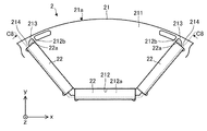
- FIG. 2 is a cross-sectional view schematically showing the structure of the rotor 2.
- the electromagnetic steel sheet shown in FIG. 2 is the first electrical steel sheet 211.
- the rotor 2 has a rotor core 21, at least one permanent magnet 22 arranged in the rotor core 21, and a shaft 23 attached to the rotor core 21.
- the rotor 2 is a permanent magnet embedded rotor.
- each magnetic pole center is indicated by the magnetic pole center line C1
- each pole-to-pole portion is indicated by the pole-to-pole line C2. That is, each magnetic pole center line C1 passes through the magnetic pole center of the rotor 2 (in other words, the center of each magnetic pole portion), and each pole-to-pole line C2 passes through the pole-to-pole portion of the rotor 2.
- the rotor 2 is rotatably provided inside the stator 3.
- the rotor 2 can rotate about the axis Ax.
- the axis Ax is the center of rotation of the rotor 2 and the axis of the shaft 23.
- the air gap between the rotor 2 and the stator 3 is, for example, 0.3 mm to 1 mm.
- the rotor core 21 has two or more first electromagnetic steel plates 211 and two or more second electrical steel plates 221. These first electromagnetic steel sheets 211 and second electrical steel sheets 221 are laminated in the axial direction. The first electromagnetic steel plate 211 and the second electrical steel plate 221 are fixed by caulking, for example.
- the rotor core 21 is a cylindrical iron core.
- the rotor core 21 is fixed to the shaft 23 by a fixing method such as shrink fitting or press fitting.
- a fixing method such as shrink fitting or press fitting.
- the rotor 2 has 18 permanent magnets 22, and the number of magnetic poles of the rotor 2 is 6 poles. Three permanent magnets 22 form one magnetic pole of the rotor 2. However, the number of magnetic poles of the rotor 2 is not limited to 6 poles.
- the shaft 23 is fixed to the rotor core 21 by a fixing method such as shrink fitting or press fitting.
- Each permanent magnet 22 is, for example, a flat plate-shaped magnet that is long in the axial direction.
- Each permanent magnet 22 arranged on the rotor core 21 is magnetized in a direction orthogonal to the longitudinal direction of the permanent magnet 22 in the xy plane. That is, in the xy plane, each permanent magnet 22 is magnetized in the lateral direction (also referred to as the thickness direction) of each permanent magnet 22.
- Each permanent magnet 22 is a rare earth magnet containing, for example, neodymium (Nd), iron (Fe), and boron (B).
- At least one permanent magnet 22 arranged on the rotor core 21 has an end portion 22a (also referred to as a first end portion).
- the end portion 22a is an end portion of the permanent magnet 22 in the longitudinal direction and an end portion facing the outer peripheral surface 21a of the rotor core.
- Each permanent magnet 22 has a substantially rectangular shape when viewed in the axial direction. That is, in the xy plane, the shape of each permanent magnet 22 is substantially rectangular.
- FIG. 3 is an enlarged view showing a part of the first electrical steel sheet 211.
- FIG. 4 is an enlarged view showing another part of the first electrical steel sheet 211.
- Each first electrical steel sheet 211 is formed in a predetermined shape.
- the thickness of each first electrical steel sheet 211 is, for example, 0.1 mm or more and 0.7 mm or less. In the present embodiment, the thickness of each first electrical steel sheet 211 is 0.35 mm. However, the thickness of each first electrical steel sheet 211 is not limited to 0.1 mm or more and 0.7 mm or less.
- Each first electrical steel sheet 211 has at least one first magnet insertion hole 212, at least one first thin-walled portion 213, at least one magnet locking portion 214, and a first shaft hole 215. Have.
- At least one permanent magnet 22 is arranged in each first magnet insertion hole 212.
- a plurality of permanent magnets 22 (three permanent magnets 22 in the examples shown in FIGS. 2 to 4) are arranged in each of the first magnet insertion holes 212. ..
- the number of permanent magnets 22 in each of the first magnet insertion holes 212 is not limited to three.
- the first magnet insertion hole 212 corresponding to one magnetic pole of the rotor 2 is a single hole.
- the leakage flux passing through the adjacent region increases. Therefore, in the present embodiment, three permanent magnets 22 are arranged in one first magnet insertion hole 212 corresponding to one magnetic pole of the rotor 2. As a result, it is possible to prevent an increase in the leakage flux.
- each first electrical steel sheet 211 has six first magnet insertion holes 212 arranged in the circumferential direction.
- the number of the first magnet insertion holes 212 is not limited to six.
- Each first magnet insertion hole 212 communicates with at least one first magnet arranging portion 212a on which at least one permanent magnet 22 is arranged and at least one first flux barrier communicating with the first magnet arranging portion 212a. It has a portion 212b. Each first magnet insertion hole 212 is a through hole.
- each first magnet insertion hole 212 In the xy plane, the central portion of the first magnet insertion hole 212 is located near the axis Ax with respect to both ends of the first magnet insertion hole 212 in the circumferential direction of the rotor core 21. In this case, in the xy plane, each first magnet insertion hole 212 may have a U-shape or a V-shape.
- At least one permanent magnet 22 is arranged in the first magnet arrangement portion 212a.
- three permanent magnets 22 are arranged in the first magnet arrangement portion 212a. Specifically, a part of each permanent magnet 22 in the axial direction is arranged in the first magnet arrangement portion 212a.
- the first magnet arranging portion 212a has three regions. One permanent magnet 22 is arranged in each region. Specifically, a part of one permanent magnet 22 in the axial direction is arranged in each region.
- the permanent magnet 22 arranged in the middle of the three permanent magnets 22 in each of the first magnet insertion holes 212 is the closest to the axis Ax among the three permanent magnets 22.
- one permanent magnet 22 is arranged so as to be orthogonal to the magnetic pole center line C1, and two permanent magnets 22 arranged on both sides of the one permanent magnet 22 with respect to the magnetic pole center line C1. Is tilted. As a result, the amount of the permanent magnets 22 at each magnetic pole portion of the rotor 2 can be increased, and the magnetic force of the rotor 2 can be increased.
- a first flux barrier portion 212b for reducing leakage flux exists at both ends of each first magnet insertion hole 212, and a first magnet arrangement portion 212a is provided between the two first flux barrier portions 212b. Existing.
- Each first flux barrier portion 212b is a space in which the permanent magnet 22 does not exist.
- Each of the first flux barrier portions 212b is provided at the outer end portion of the first magnet insertion hole 212 in the radial direction of the rotor core 21. Specifically, in each of the first magnet insertion holes 212, the two first flux barrier portions 212b are symmetrical with respect to the magnetic pole center line C1. These first flux barrier portions 212b reduce the leakage flux in the rotor 2 and improve the efficiency of the electric motor 1.
- each first electrical steel sheet 211 has 12 first thin-walled portions 213.
- the number of the first thin-walled portions 213 is not limited to 12.
- Each of the first thin-walled portions 213 is provided between the outer end portion of the first magnet insertion hole 212 in the radial direction of the rotor core 21 and the outer peripheral surface 21a of the rotor core 21. That is, each first thin-walled portion 213 is provided between the first flux barrier portion 212b and the outer peripheral surface 21a of the rotor core. In other words, each first thin-walled portion 213 is provided outside the first flux barrier portion 212b in the radial direction. Therefore, each first thin-walled portion 213 is a part of the first electromagnetic steel plate 211.
- Each first thin-walled portion 213 is provided in a region adjacent to the interpole portion of the rotor 2. As a result, magnetic flux leakage in the rotor 2 is reduced.
- the minimum width of each first thin-walled portion 213 in the xy plane shown in FIG. 4 is indicated by W1.
- the minimum width W1 of each first thin-walled portion 213 is, for example, about 1 to 1.5 times the thickness of each first electromagnetic steel sheet 211.
- the minimum width W1 of each first thin-walled portion 213 may be larger than, for example, 1.5 times the thickness of each first electromagnetic steel plate 211.
- the minimum width W1 of each first thin-walled portion 213 is 0.65 mm.
- each first electrical steel sheet 211 has 12 magnet locking portions 214.
- the number of magnet locking portions 214 is not limited to 12.
- Each magnet locking portion 214 is adjacent to the first thin-walled portion 213.
- Each magnet locking portion 214 is a part of the first electromagnetic steel plate 211.
- Each magnet locking portion 214 projects inward of the first magnet insertion hole 212.
- Each magnet locking portion 214 is in contact with the permanent magnet 22. Specifically, each magnet locking portion 214 is in contact with the end portion 22a (also referred to as the first end portion) of the permanent magnet 22. Each magnet locking portion 214 locks the permanent magnet 22 in the rotor core 21. In other words, each magnet locking portion 214 regulates the movement of the permanent magnet 22 within the rotor core 21.
- a shaft 23 is arranged in each of the first shaft holes 215.
- FIG. 5 is a plan view schematically showing the structure of the second electrical steel sheet 221.
- FIG. 6 is an enlarged view showing a part of the second electrical steel sheet 221.
- FIG. 7 is an enlarged view showing another part of the second electromagnetic steel plate 221.
- Each second electrical steel sheet 221 is formed in a predetermined shape.
- the thickness of each second electrical steel sheet 221 is, for example, 0.1 mm or more and 0.7 mm or less. In the present embodiment, the thickness of each second electrical steel sheet 221 is 0.35 mm. However, the thickness of each second electrical steel sheet 221 is not limited to 0.1 mm or more and 0.7 mm or less.
- Each second electrical steel sheet 221 has at least one second magnet insertion hole 222, at least one second thin-walled portion 223, and a second shaft hole 225.
- Each second electrical steel sheet 221 does not have a portion corresponding to the magnet locking portion 214 of the first electrical steel sheet 211. That is, each second electrical steel sheet 221 does not have a portion that comes into contact with the end portion 22a of the permanent magnet 22.
- Each second magnet insertion hole 222 communicates with the first magnet insertion hole 212. At least one permanent magnet 22 is arranged in each second magnet insertion hole 222. In the example shown in FIGS. 5 to 7, a plurality of permanent magnets 22 (three permanent magnets 22 in the examples shown in FIGS. 5 to 7) are arranged in each of the second magnet insertion holes 222. .. However, the number of permanent magnets 22 in each second magnet insertion hole 222 is not limited to three.
- each second electrical steel sheet 221 has six second magnet insertion holes 222 arranged in the circumferential direction.
- the number of the second magnet insertion holes 222 is not limited to six.
- Each second magnet insertion hole 222 communicates with at least one second magnet arrangement portion 222a in which at least one permanent magnet 22 is arranged and at least one second flux barrier communicating with the first magnet arrangement portion 212a. It has a portion 222b. Each second magnet insertion hole 222 is a through hole.
- each second magnet insertion hole 222 In the xy plane, the central portion of the second magnet insertion hole 222 is located near the axis Ax with respect to both ends of the second magnet insertion hole 222 in the circumferential direction of the rotor core 21. In this case, in the xy plane, each second magnet insertion hole 222 may have a U-shape or a V-shape.
- At least one permanent magnet 22 is arranged in the second magnet arrangement portion 222a.
- three permanent magnets 22 are arranged in the second magnet arrangement portion 222a. Specifically, a part of each permanent magnet 22 in the axial direction is arranged in the second magnet arrangement portion 222a.
- the second magnet arranging portion 222a has three regions. One permanent magnet 22 is arranged in each region. Specifically, a part of one permanent magnet 22 in the axial direction is arranged in each region.
- the second magnet insertion hole 222 corresponding to one magnetic pole of the rotor 2 is a single hole.
- the leakage flux passing through the adjacent region increases. Therefore, in the present embodiment, three permanent magnets 22 are arranged in one second magnet insertion hole 222 corresponding to one magnetic pole of the rotor 2. As a result, it is possible to prevent an increase in the leakage flux.
- the permanent magnet 22 arranged in the middle of the three permanent magnets 22 in each second magnet insertion hole 222 is the closest to the axis Ax among the three permanent magnets 22.
- one permanent magnet 22 is arranged so as to be orthogonal to the magnetic pole center line C1, and two permanent magnets 22 arranged on both sides of the one permanent magnet 22 with respect to the magnetic pole center line C1. Is tilted. As a result, the amount of the permanent magnets 22 at each magnetic pole portion of the rotor 2 can be increased, and the magnetic force of the rotor 2 can be increased.
- a second flux barrier portion 222b for reducing leakage flux exists at both ends of each second magnet insertion hole 222, and a second magnet arrangement portion 222a is provided between the two second flux barrier portions 222b. Existing.
- Each second flux barrier portion 222b is a space in which the permanent magnet 22 does not exist.
- Each second flux barrier portion 222b is provided at the outer end portion of the second magnet insertion hole 222 in the radial direction of the rotor core 21. Specifically, in each second magnet insertion hole 222, the two second flux barrier portions 222b are symmetrical with respect to the magnetic pole center line C1. These second flux barrier portions 222b reduce the leakage flux in the rotor 2 and improve the efficiency of the electric motor 1.
- each second electrical steel sheet 221 has 12 second thin-walled portions 223.
- the number of the second thin-walled portions 223 is not limited to 12.
- Each of the second thin-walled portions 223 is provided between the outer end portion of the second magnet insertion hole 222 in the radial direction of the rotor core 21 and the outer peripheral surface 21a of the rotor core 21. That is, each second thin-walled portion 223 is provided between the second flux barrier portion 222b and the outer peripheral surface 21a of the rotor core. In other words, each second thin-walled portion 223 is provided outside the second flux barrier portion 222b in the radial direction. Therefore, each second thin-walled portion 223 is a part of the second electromagnetic steel plate 221.
- Each second thin-walled portion 223 is provided in a region adjacent to the interpole portion of the rotor 2. As a result, magnetic flux leakage in the rotor 2 is reduced.
- the minimum width of each second thin-walled portion 223 in the xy plane shown in FIG. 7 is indicated by W2.
- the minimum width W2 of each second thin-walled portion 223 is, for example, about 1 to 1.5 times the thickness of each second electromagnetic steel sheet 221.
- the minimum width W2 of each second thin-walled portion 223 may be larger than, for example, 1.5 times the thickness of each second electromagnetic steel plate 221.
- the minimum width W2 of each second thin-walled portion 223 is 0.45 mm.
- the relationship between the minimum width W1 of the first thin-walled portion 213 and the minimum width W2 of the second thin-walled portion 223 satisfies W1> W2. That is, the minimum width W2 of the second thin-walled portion 223 is smaller than the minimum width W1 of the first thin-walled portion 213.
- Each second shaft hole 225 communicates with the first shaft hole 215.
- a shaft 23 is arranged in each of the second shaft holes 225.
- FIG. 8 is a cross-sectional view taken along the lines C8-C8 in FIGS. 3 and 6.
- a plurality of first electromagnetic steel sheets 211 are intermittently laminated, and a plurality of second electrical steel sheets 221 are intermittently laminated.
- first electrical steel sheets 211 and one or more second electrical steel sheets 221 may be alternately laminated.
- one first electrical steel sheet 211 and one second electrical steel sheet 221 are alternately laminated.
- the central portion of the first magnet insertion hole 212 is located near the axis Ax with respect to both ends of the first magnet insertion hole 212 in the circumferential direction of the rotor core 21.
- the central portion of the second magnet insertion hole 222 is located near the axis Ax with respect to both ends of the second magnet insertion hole 222 in the circumferential direction of the rotor core 21.
- Three permanent magnets 22 are arranged in a set of first magnet insertion holes 212 and second magnet insertion holes 222 communicating with each other. That is, three permanent magnets 22 are arranged in a set of the first magnet insertion hole 212 and the second magnet insertion hole 222 so as to have a substantially U shape in the xy plane.
- the amount of magnets at each magnetic pole portion of the rotor 2 can be increased as compared with a rotor having a plurality of permanent magnets arranged straight in the xy plane. As a result, the output density of the electric motor 1 can be improved.
- the magnitude of the centrifugal force generated in the rotor during the rotation of the rotor is proportional to the mass. Therefore, in order to improve the strength of the rotor core, it is desirable that the width of the thin portion formed between the outer peripheral surface of the rotor core and the magnet insertion hole is large. However, as the width of the thin-walled portion increases, the magnetic flux from the permanent magnet easily passes through the thin-walled portion, and the leakage flux increases. Therefore, it is desirable that the width of the thin portion is designed in consideration of the strength of the rotor core and the reduction of the leakage flux.
- each first electrical steel sheet 211 has at least one magnet locking portion 214 in contact with the end portion 22a of the permanent magnet 22.
- Each second electrical steel sheet 221 does not have a portion that comes into contact with the end portion 22a of the permanent magnet 22. Therefore, the minimum width W2 of the second thin-walled portion 223 is smaller than the minimum width W1 of the first thin-walled portion 213.
- the length of the second thin-walled portion 223 in the circumferential direction can be made longer than the length of the first thin-walled portion 213 in the circumferential direction.
- the radius of the inner edge of the second thin-walled portion 223 can be made larger than the radius of the inner edge of the first thin-walled portion 213, and in the second electromagnetic steel plate 221, the stress generated in the second thin-walled portion 223. Can be alleviated.
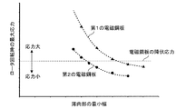
- FIG. 9 is a graph showing the relationship between the minimum width of the thin-walled portion of the electrical steel sheet in the radial direction and the maximum stress generated in the thin-walled portion during rotor rotation.
- the minimum width of the second thin-walled portion 223 when the second electromagnetic steel sheet 221 is subjected to the yield stress is the first thin-walled portion when the first electromagnetic steel sheet 211 is subjected to the yield stress. It is smaller than the minimum width of 213. That is, when the yield stress is used as a reference, the minimum width W2 of the second thin-walled portion 223 can be made smaller than the minimum width W1 of the first thin-walled portion 213.
- the leakage flux generated in the second electromagnetic steel plate 221 is caused by the leakage flux generated in the first electromagnetic steel plate 211. It can be reduced more than the magnetic flux.
- the magnetic flux from the stator core passes through the part of the rotor where the magnetic resistance is small. Therefore, the end portion of the permanent magnet facing the outer peripheral surface of the stator core is likely to be demagnetized. If the permanent magnets of the rotor are demagnetized, the efficiency and output of the motor will decrease. Further, when the permanent magnet of the rotor is demagnetized, the voltage generated in the electric motor changes, and the controllability of the electric motor deteriorates.
- each second electrical steel sheet 221 does not have a portion that comes into contact with the end portion 22a of the permanent magnet 22. Therefore, the magnetic flux from the stator core passing through the second thin-walled portion 223 having a small magnetic resistance is reduced, and the demagnetization of each permanent magnet 22 in each second electromagnetic steel plate 221 can be suppressed.
- the rotor core 21 has two or more first electromagnetic steel plates 211 and two or more second electrical steel plates 221. Therefore, the strength of the rotor 2 against centrifugal force can be increased in the first electromagnetic steel plate 211 having the magnet locking portion 214, and the permanent magnet in the second electromagnetic steel plate 221 having no portion corresponding to the magnet locking portion 214.
- the demagnetization of 22 can be suppressed. As a result, even when the number of permanent magnets 22 of the rotor 2 is increased, magnetic flux leakage and demagnetization of the permanent magnets 22 can be improved while maintaining the strength of the rotor 2. As a result, the efficiency and output of the electric motor 1 can be increased.
- first electromagnetic steel sheets 211 and one or more second electrical steel sheets 221 are alternately laminated, the above-mentioned advantages can be effectively obtained. That is, when one or more first electrical steel sheets 211 and one or more second electrical steel sheets 221 are alternately laminated, the first electrical steel sheet 211 having the magnet locking portion 214 with respect to the centrifugal force. The strength of the rotor 2 can be increased more effectively, and the demagnetization of the permanent magnet 22 can be more effectively suppressed in the second electromagnetic steel sheet 221 having no portion corresponding to the magnet locking portion 214.
- the cutting tool used in the manufacturing process of the first electrical steel sheet 211 may be replaced with the cutting tool for the second electrical steel sheet 221.
- a cutting tool that can be pressed into the shape of the second flux barrier portion 222b may be used. Therefore, the first electromagnetic steel sheet 211 and the second electrical steel sheet 221 can be easily manufactured and laminated.
- FIG. 10 is a cross-sectional view showing another example of the rotor core 21.
- the cross-sectional position in FIG. 10 corresponds to the cross-sectional position shown by lines C8 to C8 in FIG.
- the rotor core 21 has a plurality of first cores and a plurality of second cores.
- Each first core is composed of two or more first electrical steel sheets 211
- each second core is composed of two or more second electrical steel sheets 221. That is, in the first modification, the first core and the second core are arranged at equal intervals in the axial direction.
- it is desirable that the first electrical steel sheet 211 and the second electrical steel sheet 221 are symmetrically arranged with respect to the center of the rotor core 21 in the axial direction.
- the rotor core 21 shown in FIG. 10 can be applied to the rotor 2 instead of the rotor core 21 shown in FIG. Therefore, the rotor core 21 shown in FIG. 10 has the advantages described in this embodiment.
- each permanent magnet 22 when two or more first electrical steel sheets 211 and two or more second electrical steel sheets 221 are arranged at equal intervals in the axial direction, the axis of the rotor core 21 The weight balance in the direction can be improved. Further, when each permanent magnet 22 is inserted into the rotor core 21, each magnet locking portion 214 of each first electromagnetic steel plate 211 acts as a guide, so that the rotor 2 can be easily assembled. Further, even when a part of each permanent magnet 22 is demagnetized, the demagnetization imbalance in the axial direction of each permanent magnet 22 can be improved.
- the weight balance of the rotor core 21 in the axial direction can be further improved.
- FIG. 11 is a cross-sectional view showing still another example of the rotor core 21.
- the cross-sectional position of FIG. 11 corresponds to the cross-sectional position shown by lines C8 to C8 in FIG.
- the first electrical steel sheet 211 and the second electrical steel sheet 221 are arranged at equal intervals in the axial direction.
- the rotor core 21 has a plurality of first cores and a plurality of second cores.
- Each first core is composed of one or more first electrical steel sheets 211
- each second core is composed of two or more second electrical steel sheets 221. That is, in the second modification, the first core and the second core are arranged at equal intervals in the axial direction.
- it is desirable that the first electrical steel sheet 211 and the second electrical steel sheet 221 are symmetrically arranged with respect to the center of the rotor core 21 in the axial direction.
- the number of first electrical steel sheets in the rotor core 21 is N1 and the number of second electrical steel sheets in the rotor core 21 is N2, N1 ⁇ N2 is satisfied. Further, the number of first electrical steel sheets 211 constituting each first core is smaller than the number of second electrical steel sheets 221 constituting each second core.
- the rotor core 21 shown in FIG. 11 can be applied to the rotor 2 instead of the rotor core 21 shown in FIG. Therefore, the rotor core 21 shown in FIG. 11 has the advantages described in this embodiment.
- Modification example 3. 12 and 13 are cross-sectional views showing still another example of the rotor core 21.
- the cross-sectional positions of FIGS. 12 and 13 correspond to the cross-sectional positions shown by lines C8 to C8 in FIG.
- the first electrical steel sheet 211 and the second electrical steel sheet 221 are arranged at unequal intervals in the axial direction.
- the rotor core 21 has a plurality of first cores and a plurality of second cores. Each first core is composed of one or more first electrical steel sheets 211, and each second core is composed of one or more second electrical steel sheets 221.
- the number of first electrical steel sheets in the rotor core 21 is N1 and the number of second electrical steel sheets in the rotor core 21 is N2, N1 ⁇ N2 is satisfied. Further, the number of first electrical steel sheets 211 constituting each first core is smaller than the number of second electrical steel sheets 221 constituting each second core. That is, in the modified example 3, the first core and the second core are arranged at unequal intervals in the axial direction. In this case, it is desirable that the first electrical steel sheet 211 and the second electrical steel sheet 221 are symmetrically arranged with respect to the center of the rotor core 21 in the axial direction.
- the ratio of the second electromagnetic steel plate 221 in the rotor core 21 is larger than the ratio of the first electrical steel plate 211 in the rotor core 21 toward the center of the rotor core 21 in the axial direction.
- the density of the second electrical steel sheet 221 in the rotor core 21 is higher than the density of the first electrical steel sheet 211 in the rotor core 21 toward the center of the rotor core 21 in the axial direction.
- the distance between the first electromagnetic steel sheets 211 increases toward the center of the rotor core 21 in the axial direction.
- the rotor core 21 shown in FIG. 12 or 13 can be applied to the rotor 2 instead of the rotor core 21 shown in FIG. Therefore, the rotor core 21 shown in FIG. 12 or 13 has the advantages described in this embodiment.
- the proportion of the second electrical steel sheet 221 is larger than the proportion of the first electrical steel sheet 211 toward the center of the rotor core 21 in the axial direction. Thereby, magnetic flux leakage and demagnetization of the permanent magnet 22 can be effectively improved.
- the weight balance of the rotor core 21 in the axial direction can be further improved.
- the demagnetization imbalance in the axial direction of each permanent magnet 22 can be improved.
- FIG. 14 is a cross-sectional view showing still another example of the rotor core 21.
- the cross-sectional position of FIG. 14 corresponds to the cross-sectional position shown by lines C8 to C8 in FIG.
- one end of the rotor core 21 in the axial direction is composed of two or more first electromagnetic steel plates 211.
- the rotor core 21 shown in FIG. 14 can be applied to the rotor 2 instead of the rotor core 21 shown in FIG. Therefore, the rotor core 21 shown in FIG. 14 has the advantages described in this embodiment.
- each magnet locking portion 214 of each first electromagnetic steel plate 211 acts as a guide, so that the productivity of the rotor 2 is increased. Is improved. Further, when each permanent magnet 22 is inserted into the rotor core 21, it is possible to prevent the permanent magnets 22 adjacent to each other from coming into contact with each other, and it is possible to prevent damage to the permanent magnet 22.
- each first electromagnetic steel sheet 211 is formed by punching processing, sagging is formed in each magnet locking portion 214. It is desirable that this sagging be located on the downstream side of each magnet locking portion 214 in the insertion direction of the permanent magnet 22 in the manufacturing process of the rotor 2.
- the insertion direction of the permanent magnet 22 is the ⁇ z direction in FIG. As a result, each permanent magnet 22 can be easily inserted into the rotor core 21.
- each magnet locking portion 214 in the axial direction is improved. As a result, when each permanent magnet 22 is inserted into the rotor core 21, deformation of each magnet locking portion 214 can be prevented.
- each permanent magnet 22 is inserted into the rotor core 21, even if the permanent magnet 22 comes into contact with the first electromagnetic steel plate 211 arranged at one end of the rotor core 21, the first electromagnetic steel plate 211 is deformed. It can be made less likely to occur.
- FIG. 15 is a cross-sectional view showing still another example of the rotor core 21.
- the cross-sectional position of FIG. 15 corresponds to the cross-sectional position shown by lines C8 to C8 in FIG.
- both ends of the rotor core 21 in the axial direction are composed of two or more first electromagnetic steel plates 211.
- the rotor core 21 shown in FIG. 15 can be applied to the rotor 2 instead of the rotor core 21 shown in FIG. Therefore, the rotor core 21 shown in FIG. 15 has the advantages described in this embodiment.
- both ends of the rotor core 21 in the axial direction are composed of two or more first electrical steel sheets 211
- the first electrical steel sheets 211 of each permanent magnet 22 are inserted. Since each magnet locking portion 214 serves as a guide, each permanent magnet 22 can be easily inserted into the rotor core 21 from the upper part or the lower part of the rotor core 21. As a result, the productivity of the rotor 2 is improved.
- FIG. 16 is a cross-sectional view showing still another example of the rotor core 21.
- the cross-sectional position of FIG. 16 corresponds to the cross-sectional position shown by lines C8 to C8 in FIG.
- the rotor 2 satisfies L1> Ld.
- L1 is the shortest distance from one end of the first electrical steel sheet 211 in the axial direction to the end of the rotor core 21 in the axial direction.
- Ld is the difference between the length Lr and the length Lm.
- the length Lr is the length of the rotor core 21 in the axial direction.
- the length Lm is the length of each permanent magnet 22 in the axial direction.
- each magnet locking portion 214 of at least one first electromagnetic steel plate 211 is located on the center side of the rotor core 21 in the axial direction with respect to both end portions of the permanent magnet 22. Therefore, at least one permanent magnet 22 is regulated by at least one magnet locking portion 214.
- the rotor core 21 shown in FIG. 16 can be applied to the rotor 2 instead of the rotor core 21 shown in FIG. Therefore, the rotor core 21 shown in FIG. 16 has the advantages described in this embodiment.
- FIG. 17 is a diagram showing an example in which the permanent magnet 22 in the rotor core 21 shown in FIG. 16 is displaced in the axial direction.
- the permanent magnet 22 is displaced to one side in the axial direction, the magnet engagement of the first electromagnetic steel plate 211 arranged on one end side of the rotor core 21 in the axial direction.
- the stop portion 214 restricts the movement of the permanent magnet 22 in the radial direction.
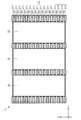
- FIG. 18 is a cross-sectional view showing still another example of the rotor core 21.
- the cross-sectional position of FIG. 18 corresponds to the cross-sectional position shown by lines C8 to C8 in FIG.
- the first end portion of the rotor core 21 in the axial direction is composed of two or more first electromagnetic steel plates 211.
- the first end of the rotor core 21 in the axial direction is the area indicated by hatching.
- the rotor 2 satisfies Lr> Lm and L1t> Ld.
- the width L1t is the width in the axial direction of two or more first electrical steel sheets 211 arranged at the first end of the rotor core 21.
- the length Lr is the length of the rotor core 21 in the axial direction.
- the length Lm is the length of each permanent magnet 22 in the axial direction.
- the length Ld is the difference between the length Lr and the length Lm.
- the rotor core 21 shown in FIG. 18 can be applied to the rotor 2 instead of the rotor core 21 shown in FIG. Therefore, the rotor core 21 shown in FIG. 18 has the advantages described in this embodiment.
- the rotor 2 satisfies L1t> Ld.
- each magnet locking portion 214 of each first electromagnetic steel plate 211 serves as a guide at at least the first end portion of the rotor core 21 in the axial direction. Fulfill. Therefore, when each permanent magnet 22 is inserted into the rotor core 21, each magnet locking portion 214 of each first electromagnetic steel plate 211 serves as a guide at least one end side of the rotor core 21 in the axial direction, so that the rotor core Each permanent magnet 22 can be easily inserted into the rotor core 21 from the upper part or the lower part of the 21. As a result, the productivity of the rotor 2 is improved.
- FIG. 19 is a cross-sectional view showing still another example of the rotor core 21.
- the cross-sectional position in FIG. 19 corresponds to the cross-sectional position shown by lines C8 to C8 in FIG.
- the first end portion of the rotor core 21 in the axial direction is composed of two or more first electromagnetic steel plates 211
- the second end portion of the rotor core 21 in the axial direction is two or more. It is composed of the first electromagnetic steel sheet 211 of the above.
- the first end of the rotor core 21 in the axial direction is the area indicated by hatching.
- the second end of the rotor core 21 in the axial direction is the area indicated by hatching.
- the rotor core 21 has two or more first electrical steel sheets 211 arranged at the first end of the rotor core 21 in the axial direction, and is arranged at the second end of the rotor core 21 in the axial direction. It further has two or more first electrical steel sheets 211.
- the second end of the rotor core 21 is located on the opposite side of the first end of the rotor core 21 in the axial direction.
- the two or more first electrical steel sheets 211 arranged at the first end of the rotor core 21 are also referred to as the "first core", and the two or more first ones arranged at the second end of the rotor core 21.
- the electromagnetic steel plate 211 is also referred to as a second core.
- Two or more second electrical steel sheets 221 are arranged between the first core and the second core.
- the rotor 2 satisfies Lr> Lm, L1t> Ld, and L1b> Ld.
- the width L1t is the width in the axial direction of two or more first electrical steel sheets 211 arranged at the first end of the rotor core 21.
- the width L1b is the width in the axial direction of two or more first electrical steel sheets 211 arranged at the second end of the rotor core 21.
- the length Lr is the length of the rotor core 21 in the axial direction.
- the length Lm is the length of each permanent magnet 22 in the axial direction.
- the length Ld is the difference between the length Lr and the length Lm.
- the rotor core 21 shown in FIG. 19 can be applied to the rotor 2 instead of the rotor core 21 shown in FIG. Therefore, the rotor core 21 shown in FIG. 19 has the advantages described in this embodiment.
- FIG. 20 is a graph showing the magnitudes of the magnetic force and demagnetization strength of the rotor 2 when a comparative example is used as a reference.
- a comparative example is a rotor in which the rotor core is composed of only one or more first electrical steel sheets 211. That is, the rotor core in the comparative example does not have the second electromagnetic steel plate 221.
- the horizontal axis of FIG. 20 shows the ratio of the second electrical steel sheet 221 to the rotor core 21 in the axial direction. Specifically, the horizontal axis of FIG. 20 shows the ratio of the total width of the second electromagnetic steel sheet 221 in the axial direction to the width of the rotor core 21 in the axial direction.
- the ratio of the total width of the second electromagnetic steel sheet 221 in the axial direction to the width of the rotor core 21 in the axial direction is 0.50.
- the ratio of the total width of the second electrical steel sheet 221 in the axial direction to the width of the rotor core 21 in the axial direction is 0.94.
- the ratio of the total width of the second electrical steel sheet 221 in the axial direction to the width of the rotor core 21 in the axial direction is preferably larger than 0.10 and smaller than 1.00. ..
- the ratio of the total width of the second electromagnetic steel sheet 221 in the axial direction to the width of the rotor core 21 in the axial direction is more preferably 0.50 or more and 0.94 or less.
- FIG. 21 is a cross-sectional view schematically showing the structure of the compressor 6 according to the second embodiment.
- the compressor 6 has an electric motor 1 as an electric element, a shell 61 (also referred to as a closed container) as a housing, and a compression mechanism 62 as a compression element (also referred to as a compression device).
- the compressor 6 is a rotary compressor.
- the compressor 6 is not limited to the rotary compressor.
- the compressor 6 is used, for example, in a refrigeration cycle in an air conditioner.
- the electric motor 1 in the compressor 6 is the electric motor 1 described in the first embodiment.
- the electric motor 1 drives the compression mechanism 62.
- the shell 61 covers the electric motor 1 and the compression mechanism 62.
- the shell 61 is a cylindrical container.
- the shell 61 is made of, for example, a steel plate.
- the shell 61 may be divided into an upper shell and a lower shell, or may be a single structure. Refrigerating machine oil that lubricates the sliding portion of the compression mechanism 62 is stored in the bottom of the shell 61.
- the compressor 6 further includes a glass terminal 63 fixed to the shell 61, an accumulator 64, a suction pipe 65, and a discharge pipe 66 for discharging the refrigerant to the outside of the compressor 6.
- the compression mechanism 62 is attached to the cylinder 62a, the piston 62b, the upper frame 62c (also referred to as the first frame), the lower frame 62d (also referred to as the second frame), and the upper frame 62c and the lower frame 62d. It has a plurality of mufflers 62e.
- the compression mechanism 62 further has a vane that divides the region in the cylinder 62a into a suction side and a compression side.
- the compression mechanism 62 is arranged in the shell 61.
- the compression mechanism 62 is driven by the electric motor 1.
- the glass terminal 63 is a terminal for supplying electric power from the power source to the electric motor 1 in the compressor 6.
- Electric power is supplied to the coil of the electric motor 1 (for example, the winding 32 described in the first embodiment) through the glass terminal 63.
- the rotor 2 (specifically, one side of the shaft 23) of the electric motor 1 is rotatably supported by bearings provided on each of the upper frame 62c and the lower frame 62d.
- a shaft 23 is inserted through the piston 62b.
- a shaft 23 is rotatably inserted into the upper frame 62c and the lower frame 62d. As a result, the shaft 23 can transmit the power of the electric motor 1 to the compression mechanism 62.
- the upper frame 62c and the lower frame 62d close the end faces of the cylinder 62a.
- the accumulator 64 supplies a refrigerant (for example, a refrigerant gas) to the cylinder 62a through the suction pipe 65.
- the refrigerant supplied from the accumulator 64 is sucked into the cylinder 62a from the suction pipe 65 fixed to the shell 61.
- the piston 62b fitted to the shaft 23 rotates in the cylinder 62a.
- the refrigerant is compressed in the cylinder 62a.
- the compressed refrigerant passes through the muffler 62e and rises in the shell 61. In this way, the compressed refrigerant is supplied to the high pressure side of the refrigeration cycle through the discharge pipe 66.
- R410A, R407C, R22, or the like can be used as the refrigerant of the compressor 6.
- the refrigerant of the compressor 6 is not limited to these types.
- a refrigerant having a small global warming potential (GWP) for example, the following refrigerant can be used.
- the GWP of HFO-1234yf is 4.
- a hydrocarbon having a carbon double bond in the composition for example, R1270 (propylene) may be used.
- the GWP of R1270 is 3, which is lower than HFO-1234yf but higher in flammability than HFO-1234yf.
- a halogenated hydrocarbon having a carbon double bond in the composition or a mixture containing a hydrocarbon having a carbon double bond in the composition may be used, and both the halogenated hydrocarbon and the hydrocarbon thereof may be used.
- a mixture containing the above may be used.
- a mixture of HFO-1234yf and R32 may be used. Since the above-mentioned HFO-1234yf is a low-pressure refrigerant, the pressure loss tends to be large, which may lead to deterioration of the performance of the refrigeration cycle (particularly the evaporator). Therefore, it is practically desirable to use a mixture containing R32 or R41, which is a higher pressure refrigerant than HFO-1234yf.
- the compressor 6 according to the second embodiment has the advantages described in the first embodiment.
- the compressor 6 according to the second embodiment has the electric motor 1 according to the first embodiment, the efficiency of the compressor 6 can be improved.
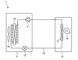
- FIG. 22 is a diagram schematically showing the configuration of the refrigerating air conditioner 7 according to the third embodiment.
- the refrigerating and air-conditioning device 7 can be operated for heating and cooling, for example.
- the refrigerant circuit diagram shown in FIG. 22 is an example of a refrigerant circuit diagram of an air conditioner capable of cooling operation.
- the refrigerating and air-conditioning device 7 has an outdoor unit 71, an indoor unit 72, and a refrigerant pipe 73 connecting the outdoor unit 71 and the indoor unit 72.
- the outdoor unit 71 includes a compressor 6, a condenser 74 as a heat exchanger, a throttle device 75, and an outdoor blower 76 (also referred to as a “blower”).
- the condenser 74 condenses the refrigerant compressed by the compressor 6.
- the drawing device 75 decompresses the refrigerant condensed by the condenser 74 and adjusts the flow rate of the refrigerant.
- the diaphragm device 75 is also referred to as a decompression device.
- the indoor unit 72 has an evaporator 77 as a heat exchanger and an indoor blower 78 (also referred to as a “blower”).
- the evaporator 77 evaporates the refrigerant decompressed by the throttle device 75 to cool the indoor air.
- the refrigerant is compressed by the compressor 6 and flows into the condenser 74.
- the refrigerant is condensed by the condenser 74, and the condensed refrigerant flows into the drawing device 75.
- the refrigerant is decompressed by the throttle device 75, and the decompressed refrigerant flows into the evaporator 77.
- the refrigerant evaporates in the evaporator 77, and the refrigerant (specifically, the refrigerant gas) flows into the compressor 6 of the outdoor unit 71 again.
- the configuration and operation of the refrigerating air conditioner 7 described above is an example, and is not limited to the above-mentioned example.
- the refrigerating air conditioner 7 according to the third embodiment, it has the advantages described in the first and second embodiments.
- the refrigerating and air-conditioning device 7 according to the third embodiment has the compressor 6 according to the second embodiment, the efficiency of the refrigerating and air-conditioning device 7 can be improved.
Landscapes
- Engineering & Computer Science (AREA)
- Power Engineering (AREA)
- Physics & Mathematics (AREA)
- Mechanical Engineering (AREA)
- Thermal Sciences (AREA)
- General Engineering & Computer Science (AREA)
- Permanent Field Magnets Of Synchronous Machinery (AREA)
- Iron Core Of Rotating Electric Machines (AREA)
Priority Applications (4)
| Application Number | Priority Date | Filing Date | Title |
|---|---|---|---|
| CN201980100985.6A CN114503397A (zh) | 2019-10-11 | 2019-10-11 | 转子、电动机、压缩机以及空气调节机 |
| US17/637,593 US20220286004A1 (en) | 2019-10-11 | 2019-10-11 | Rotor, motor, compressor, and air conditioner |
| JP2021551066A JP7237178B2 (ja) | 2019-10-11 | 2019-10-11 | ロータ、電動機、圧縮機、及び空気調和機 |
| PCT/JP2019/040174 WO2021070353A1 (ja) | 2019-10-11 | 2019-10-11 | ロータ、電動機、圧縮機、及び空気調和機 |
Applications Claiming Priority (1)
| Application Number | Priority Date | Filing Date | Title |
|---|---|---|---|
| PCT/JP2019/040174 WO2021070353A1 (ja) | 2019-10-11 | 2019-10-11 | ロータ、電動機、圧縮機、及び空気調和機 |
Publications (1)
| Publication Number | Publication Date |
|---|---|
| WO2021070353A1 true WO2021070353A1 (ja) | 2021-04-15 |
Family
ID=75438116
Family Applications (1)
| Application Number | Title | Priority Date | Filing Date |
|---|---|---|---|
| PCT/JP2019/040174 Ceased WO2021070353A1 (ja) | 2019-10-11 | 2019-10-11 | ロータ、電動機、圧縮機、及び空気調和機 |
Country Status (4)
| Country | Link |
|---|---|
| US (1) | US20220286004A1 (https=) |
| JP (1) | JP7237178B2 (https=) |
| CN (1) | CN114503397A (https=) |
| WO (1) | WO2021070353A1 (https=) |
Cited By (2)
| Publication number | Priority date | Publication date | Assignee | Title |
|---|---|---|---|---|
| DE102021131592A1 (de) | 2021-12-01 | 2023-06-01 | Bayerische Motoren Werke Aktiengesellschaft | Blechpaket mit selektiver Streusteggestaltung, Rotor, elektrische Maschine sowie Kraftfahrzeug |
| US20230299627A1 (en) * | 2022-03-17 | 2023-09-21 | Toyota Jidosha Kabushiki Kaisha | Rotor |
Families Citing this family (1)
| Publication number | Priority date | Publication date | Assignee | Title |
|---|---|---|---|---|
| CN116827014A (zh) * | 2023-06-21 | 2023-09-29 | 浙江大学 | 一种同步电机用磁桥式转子结构 |
Citations (4)
| Publication number | Priority date | Publication date | Assignee | Title |
|---|---|---|---|---|
| JP2006033982A (ja) * | 2004-07-15 | 2006-02-02 | Mitsubishi Electric Corp | 回転電機の回転子 |
| JP2013251930A (ja) * | 2012-05-30 | 2013-12-12 | Mitsui High Tec Inc | 積層鉄心の製造方法 |
| JP2019126102A (ja) * | 2016-05-11 | 2019-07-25 | 三菱電機株式会社 | 回転子および回転電機 |
| JP2019146484A (ja) * | 2019-06-03 | 2019-08-29 | 三菱電機株式会社 | 電動機、ロータ、圧縮機および冷凍空調装置 |
Family Cites Families (9)
| Publication number | Priority date | Publication date | Assignee | Title |
|---|---|---|---|---|
| JP4121673B2 (ja) * | 1999-07-16 | 2008-07-23 | 松下電器産業株式会社 | 永久磁石型同期電動機 |
| JP4666500B2 (ja) * | 2005-12-27 | 2011-04-06 | 三菱電機株式会社 | 永久磁石埋込型モータの回転子 |
| JP2010226830A (ja) * | 2009-03-23 | 2010-10-07 | Mitsubishi Electric Corp | 電動機及びそれを搭載した圧縮機 |
| JP2012115016A (ja) * | 2010-11-24 | 2012-06-14 | Toyota Motor Corp | 回転電機 |
| JP5974672B2 (ja) * | 2012-06-27 | 2016-08-23 | トヨタ紡織株式会社 | ロータコアの製造方法 |
| EP2916434B1 (en) * | 2012-11-01 | 2017-07-19 | Mitsubishi Electric Corporation | Electric motor with embedded permanent magnet, compressor, and refrigeration and air conditioning equipment |
| EP2961040B1 (en) * | 2013-02-20 | 2019-05-08 | Mitsubishi Electric Corporation | Electric motor having embedded permanent magnets |
| JP2015053831A (ja) * | 2013-09-09 | 2015-03-19 | トヨタ自動車株式会社 | 回転電機のロータ |
| GB2558101B (en) * | 2015-10-30 | 2021-11-03 | Mitsubishi Electric Corp | Motor, rotor, compressor, and refrigeration and air conditioning apparatus |
-
2019
- 2019-10-11 WO PCT/JP2019/040174 patent/WO2021070353A1/ja not_active Ceased
- 2019-10-11 US US17/637,593 patent/US20220286004A1/en not_active Abandoned
- 2019-10-11 CN CN201980100985.6A patent/CN114503397A/zh active Pending
- 2019-10-11 JP JP2021551066A patent/JP7237178B2/ja active Active
Patent Citations (4)
| Publication number | Priority date | Publication date | Assignee | Title |
|---|---|---|---|---|
| JP2006033982A (ja) * | 2004-07-15 | 2006-02-02 | Mitsubishi Electric Corp | 回転電機の回転子 |
| JP2013251930A (ja) * | 2012-05-30 | 2013-12-12 | Mitsui High Tec Inc | 積層鉄心の製造方法 |
| JP2019126102A (ja) * | 2016-05-11 | 2019-07-25 | 三菱電機株式会社 | 回転子および回転電機 |
| JP2019146484A (ja) * | 2019-06-03 | 2019-08-29 | 三菱電機株式会社 | 電動機、ロータ、圧縮機および冷凍空調装置 |
Cited By (2)
| Publication number | Priority date | Publication date | Assignee | Title |
|---|---|---|---|---|
| DE102021131592A1 (de) | 2021-12-01 | 2023-06-01 | Bayerische Motoren Werke Aktiengesellschaft | Blechpaket mit selektiver Streusteggestaltung, Rotor, elektrische Maschine sowie Kraftfahrzeug |
| US20230299627A1 (en) * | 2022-03-17 | 2023-09-21 | Toyota Jidosha Kabushiki Kaisha | Rotor |
Also Published As
| Publication number | Publication date |
|---|---|
| CN114503397A (zh) | 2022-05-13 |
| JPWO2021070353A1 (https=) | 2021-04-15 |
| US20220286004A1 (en) | 2022-09-08 |
| JP7237178B2 (ja) | 2023-03-10 |
Similar Documents
| Publication | Publication Date | Title |
|---|---|---|
| JP7362801B2 (ja) | 電動機、圧縮機、送風機、及び冷凍空調装置 | |
| JP6109338B2 (ja) | 永久磁石埋込型電動機、圧縮機及び冷凍空調装置 | |
| JP7195408B2 (ja) | ロータ、モータ、圧縮機、及び空気調和機 | |
| CN105594099A (zh) | 永磁铁埋入型电动机、压缩机以及制冷空调装置 | |
| JP7150181B2 (ja) | モータ、圧縮機、及び空気調和機 | |
| CN106797148A (zh) | 永久磁铁嵌入式电动机、压缩机以及制冷空调机 | |
| JPWO2020021693A1 (ja) | 電動機、圧縮機、及び空気調和機 | |
| JP7204897B2 (ja) | ロータ、モータ、圧縮機、及び空気調和機 | |
| JP7237178B2 (ja) | ロータ、電動機、圧縮機、及び空気調和機 | |
| JP7154373B2 (ja) | 電動機、圧縮機、及び空気調和機 | |
| JP7034328B2 (ja) | ロータ、モータ、圧縮機、及び冷凍空調装置 | |
| WO2022208740A1 (ja) | モータ、圧縮機および冷凍サイクル装置 | |
| JPWO2020026431A1 (ja) | ステータ、モータ、圧縮機、及び冷凍空調装置 | |
| JP7345562B2 (ja) | ステータ、モータ、圧縮機、及び空気調和機 |
Legal Events
| Date | Code | Title | Description |
|---|---|---|---|
| 121 | Ep: the epo has been informed by wipo that ep was designated in this application |
Ref document number: 19948301 Country of ref document: EP Kind code of ref document: A1 |
|
| ENP | Entry into the national phase |
Ref document number: 2021551066 Country of ref document: JP Kind code of ref document: A |
|
| NENP | Non-entry into the national phase |
Ref country code: DE |
|
| 122 | Ep: pct application non-entry in european phase |
Ref document number: 19948301 Country of ref document: EP Kind code of ref document: A1 |