WO2021065959A1 - 充電制御装置 - Google Patents
充電制御装置 Download PDFInfo
- Publication number
- WO2021065959A1 WO2021065959A1 PCT/JP2020/037026 JP2020037026W WO2021065959A1 WO 2021065959 A1 WO2021065959 A1 WO 2021065959A1 JP 2020037026 W JP2020037026 W JP 2020037026W WO 2021065959 A1 WO2021065959 A1 WO 2021065959A1
- Authority
- WO
- WIPO (PCT)
- Prior art keywords
- temperature
- secondary battery
- charging
- value
- battery
- Prior art date
Links
Images


Classifications
-
- H—ELECTRICITY
- H02—GENERATION; CONVERSION OR DISTRIBUTION OF ELECTRIC POWER
- H02J—CIRCUIT ARRANGEMENTS OR SYSTEMS FOR SUPPLYING OR DISTRIBUTING ELECTRIC POWER; SYSTEMS FOR STORING ELECTRIC ENERGY
- H02J7/00—Circuit arrangements for charging or depolarising batteries or for supplying loads from batteries
- H02J7/00032—Circuit arrangements for charging or depolarising batteries or for supplying loads from batteries characterised by data exchange
- H02J7/00038—Circuit arrangements for charging or depolarising batteries or for supplying loads from batteries characterised by data exchange using passive battery identification means, e.g. resistors or capacitors
- H02J7/00041—Circuit arrangements for charging or depolarising batteries or for supplying loads from batteries characterised by data exchange using passive battery identification means, e.g. resistors or capacitors in response to measured battery parameters, e.g. voltage, current or temperature profile
-
- H—ELECTRICITY
- H02—GENERATION; CONVERSION OR DISTRIBUTION OF ELECTRIC POWER
- H02J—CIRCUIT ARRANGEMENTS OR SYSTEMS FOR SUPPLYING OR DISTRIBUTING ELECTRIC POWER; SYSTEMS FOR STORING ELECTRIC ENERGY
- H02J7/00—Circuit arrangements for charging or depolarising batteries or for supplying loads from batteries
- H02J7/02—Circuit arrangements for charging or depolarising batteries or for supplying loads from batteries for charging batteries from ac mains by converters
- H02J7/04—Regulation of charging current or voltage
-
- H—ELECTRICITY
- H02—GENERATION; CONVERSION OR DISTRIBUTION OF ELECTRIC POWER
- H02J—CIRCUIT ARRANGEMENTS OR SYSTEMS FOR SUPPLYING OR DISTRIBUTING ELECTRIC POWER; SYSTEMS FOR STORING ELECTRIC ENERGY
- H02J7/00—Circuit arrangements for charging or depolarising batteries or for supplying loads from batteries
- H02J7/0029—Circuit arrangements for charging or depolarising batteries or for supplying loads from batteries with safety or protection devices or circuits
- H02J7/00309—Overheat or overtemperature protection
-
- H—ELECTRICITY
- H01—ELECTRIC ELEMENTS
- H01M—PROCESSES OR MEANS, e.g. BATTERIES, FOR THE DIRECT CONVERSION OF CHEMICAL ENERGY INTO ELECTRICAL ENERGY
- H01M10/00—Secondary cells; Manufacture thereof
- H01M10/42—Methods or arrangements for servicing or maintenance of secondary cells or secondary half-cells
- H01M10/44—Methods for charging or discharging
- H01M10/443—Methods for charging or discharging in response to temperature
-
- H—ELECTRICITY
- H01—ELECTRIC ELEMENTS
- H01M—PROCESSES OR MEANS, e.g. BATTERIES, FOR THE DIRECT CONVERSION OF CHEMICAL ENERGY INTO ELECTRICAL ENERGY
- H01M10/00—Secondary cells; Manufacture thereof
- H01M10/42—Methods or arrangements for servicing or maintenance of secondary cells or secondary half-cells
- H01M10/48—Accumulators combined with arrangements for measuring, testing or indicating the condition of cells, e.g. the level or density of the electrolyte
- H01M10/486—Accumulators combined with arrangements for measuring, testing or indicating the condition of cells, e.g. the level or density of the electrolyte for measuring temperature
-
- H—ELECTRICITY
- H02—GENERATION; CONVERSION OR DISTRIBUTION OF ELECTRIC POWER
- H02J—CIRCUIT ARRANGEMENTS OR SYSTEMS FOR SUPPLYING OR DISTRIBUTING ELECTRIC POWER; SYSTEMS FOR STORING ELECTRIC ENERGY
- H02J7/00—Circuit arrangements for charging or depolarising batteries or for supplying loads from batteries
- H02J7/0047—Circuit arrangements for charging or depolarising batteries or for supplying loads from batteries with monitoring or indicating devices or circuits
- H02J7/0048—Detection of remaining charge capacity or state of charge [SOC]
-
- H—ELECTRICITY
- H02—GENERATION; CONVERSION OR DISTRIBUTION OF ELECTRIC POWER
- H02J—CIRCUIT ARRANGEMENTS OR SYSTEMS FOR SUPPLYING OR DISTRIBUTING ELECTRIC POWER; SYSTEMS FOR STORING ELECTRIC ENERGY
- H02J7/00—Circuit arrangements for charging or depolarising batteries or for supplying loads from batteries
- H02J7/007—Regulation of charging or discharging current or voltage
- H02J7/00712—Regulation of charging or discharging current or voltage the cycle being controlled or terminated in response to electric parameters
- H02J7/00714—Regulation of charging or discharging current or voltage the cycle being controlled or terminated in response to electric parameters in response to battery charging or discharging current
-
- H—ELECTRICITY
- H02—GENERATION; CONVERSION OR DISTRIBUTION OF ELECTRIC POWER
- H02J—CIRCUIT ARRANGEMENTS OR SYSTEMS FOR SUPPLYING OR DISTRIBUTING ELECTRIC POWER; SYSTEMS FOR STORING ELECTRIC ENERGY
- H02J7/00—Circuit arrangements for charging or depolarising batteries or for supplying loads from batteries
- H02J7/007—Regulation of charging or discharging current or voltage
- H02J7/007188—Regulation of charging or discharging current or voltage the charge cycle being controlled or terminated in response to non-electric parameters
- H02J7/007192—Regulation of charging or discharging current or voltage the charge cycle being controlled or terminated in response to non-electric parameters in response to temperature
- H02J7/007194—Regulation of charging or discharging current or voltage the charge cycle being controlled or terminated in response to non-electric parameters in response to temperature of the battery
-
- Y—GENERAL TAGGING OF NEW TECHNOLOGICAL DEVELOPMENTS; GENERAL TAGGING OF CROSS-SECTIONAL TECHNOLOGIES SPANNING OVER SEVERAL SECTIONS OF THE IPC; TECHNICAL SUBJECTS COVERED BY FORMER USPC CROSS-REFERENCE ART COLLECTIONS [XRACs] AND DIGESTS
- Y02—TECHNOLOGIES OR APPLICATIONS FOR MITIGATION OR ADAPTATION AGAINST CLIMATE CHANGE
- Y02E—REDUCTION OF GREENHOUSE GAS [GHG] EMISSIONS, RELATED TO ENERGY GENERATION, TRANSMISSION OR DISTRIBUTION
- Y02E60/00—Enabling technologies; Technologies with a potential or indirect contribution to GHG emissions mitigation
- Y02E60/10—Energy storage using batteries
Definitions
- the present disclosure relates to a charge control device that controls charge of a secondary battery.
- a control device of this type that predicts a temperature rise of a secondary battery based on the current temperature of the secondary battery and the current charge / discharge current. Based on the prediction result, this control device selects one upper limit charge / discharge current value from a plurality of upper limit charge / discharge current values so that the temperature of the secondary battery does not exceed the upper limit temperature. This prevents the secondary battery from becoming overheated during charge / discharge control of the secondary battery, and thus prevents deterioration of the secondary battery.
- the control device described in Patent Document 1 predicts the temperature rise of the secondary battery based on the current temperature of the secondary battery and the current charging current at specific time intervals. Will be done. Therefore, the upper limit charging current of the secondary battery can be changed at specific time intervals, and the charging current of the secondary current can be changed. As a result, there is a concern that the charging period of the secondary battery will vary greatly.
- the main object of the present disclosure is to provide a charge control device capable of preventing the secondary battery from becoming overheated and suppressing a large variation in the charging period of the secondary battery.
- the present disclosure is applied to a system including a secondary battery and a charger electrically connected to the secondary battery, and charge control for controlling the charge of the secondary battery by operating the charger.
- An acquisition unit that acquires the temperature of the secondary battery and a charging parameter that is either the charging current or the charging power of the secondary battery.
- the said from the start of charging of the secondary battery to the elapse of the specified period.
- a learning unit that learns battery characteristic information including information related to the temperature rise rate, which is the amount of temperature rise of the secondary battery, and the charging parameters of the secondary battery.
- a command value calculation unit that calculates a command value of the charging parameter over the specified period from the charging start timing of the secondary battery based on the stored battery characteristic information. It includes an operation unit that operates the charger so as to control the charging parameter from the charging start timing of the secondary battery to the calculated command value.
- the command value of the charging parameter is calculated based on the difference between the initial temperature and the limit temperature of the secondary battery, the limit temperature rise rate calculated based on the specified period, and the battery characteristic information stored in the storage unit. Will be done. Therefore, as a command value used for a specified period from the charging start timing of the secondary battery, a command value can be set so that the temperature of the secondary battery does not exceed the limit temperature, and the secondary battery can be set during charge control. Can be prevented from becoming overheated.
- battery characteristic information including the temperature rise rate used in calculating the command value is learned based on the temperature and charging parameters of the secondary battery. Therefore, it is possible to improve the accuracy of calculating the command value so that the temperature of the secondary battery does not exceed the limit temperature.
- a command value over a specified period is calculated from the charging start timing, and the calculated command value is basically used over that period. Be done. Therefore, it is possible to prevent the charging period of the secondary battery from deviating significantly from the specified period.
- FIG. 1 is an overall configuration diagram of an in-vehicle charging system according to the first embodiment.
- FIG. 2 is a diagram showing a control unit and a sensor or the like as a peripheral configuration thereof.
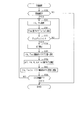
- FIG. 3 is a flowchart showing the procedure of the charge control process.
- FIG. 4 is a diagram showing an outline of the charging current map.
- FIG. 5 is a diagram showing the relationship between the temperature deviation and the correction amount.
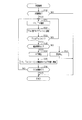
- FIG. 6 is a flowchart showing the procedure of the learning process.
- FIG. 7 is a diagram showing the relationship between the internal resistance value of the secondary battery and the temperature determination value.
- FIG. 8 is a diagram showing a learning mode of the temperature rise rate.
- FIG. 9 is a time chart showing an example of charge control processing.
- FIG. 10 is a flowchart showing the procedure of the charge control process according to the second embodiment.
- FIG. 11 is a flowchart showing the procedure of the learning process.
- FIG. 12 is a diagram showing the relationship between the charging current, the internal resistance value, and the calorific value.
- FIG. 13 is a flowchart showing the procedure of the charge control process according to the third embodiment.
- FIG. 14 is a flowchart showing the procedure of the learning process.
- FIG. 15 is a diagram showing the relationship between the charging current, the heat capacity, and the calorific value.
- FIG. 16 is a flowchart showing the procedure of the learning process according to the fourth embodiment.
- FIG. 17 is a flowchart showing the procedure of the charge control process according to the fifth embodiment.
- the vehicle 10 includes a secondary battery 11 and a rotary electric machine 12.
- the secondary battery 11 is, for example, a lithium ion storage battery or a nickel hydrogen storage battery, and in the present embodiment, an assembled battery is assumed.
- the rotary electric machine 12 becomes a traveling power source for the vehicle 10 by being driven by being supplied with power from the secondary battery 11.
- the vehicle 10 includes a battery monitoring device 13, a charger 14, and a control unit 15.
- the battery monitoring device 13 has a function of detecting the terminal voltage and the like of each battery cell constituting the secondary battery 11 and a function of calculating the SOC and the like of each battery cell.
- the charger 14 is a device for charging the secondary battery 11 with electric power supplied from a power supply facility provided outside the vehicle 10.
- the vehicle 10 includes a temperature sensor 20, a voltage sensor 21, and a current sensor 22.
- the temperature sensor 20 detects the temperature of the secondary battery 11
- the voltage sensor 21 detects the terminal voltage of the secondary battery 11
- the current sensor 22 detects the current flowing through the secondary battery 11.
- the detected values of the sensors 20 to 22 and the information such as the SOC calculated by the battery monitoring device 13 are input to the control unit 15.
- the control unit 15 performs a charge control process from the charger 14 to the secondary battery 11 based on the input detection value and information.
- the function provided by the control unit 15 can be provided by, for example, software recorded in a physical memory device, a computer for executing the software, hardware, or a combination thereof.
- FIG. 3 shows the procedure of charge control processing. This process is executed when the control unit 15 determines that there is a request for charging the secondary battery 11.
- step S10 the initial temperature Tini, which is the temperature of the secondary battery 11 detected by the temperature sensor 20 before the start of charging the secondary battery 11, is acquired.
- the allowable temperature increase amount ⁇ Tlimit is calculated by subtracting the initial temperature Tini from the limit temperature Tblimit of the secondary battery 11.
- the limit temperature Tblimit is set to, for example, an allowable upper limit temperature of the secondary battery 11 that can avoid the prevention of deterioration of the secondary battery 11.
- step S11 the limit temperature rise rate ⁇ Ttgt is calculated by dividing the permissible temperature rise amount ⁇ Tlimit by the specified period TL.
- the specified period TL is set to the period for charging the secondary battery 11 under constant current control.
- step S12 the commanded charging current Itgt of the secondary battery 11 is calculated based on the charging current map in which the commanded charging current Itgt is defined in relation to the initial temperature Tini and the temperature rise rate ⁇ T.
- the temperature rise rate ⁇ T is a value that defines the amount of temperature rise of the secondary battery 11 from the start of charging of the secondary battery to the elapse of the specified period TL.
- step S12 among the commanded charging current Itgt defined in the charging current map, the initial temperature Tini acquired in step S10 and the temperature rising rate ⁇ T having the same value as the limit temperature rising rate ⁇ Ttgt calculated in step S11 correspond to each other.
- the commanded charging current Itgt is calculated by selecting the commanded charging current Itgt.
- the processing in steps S10 to S12 corresponds to the "command value calculation unit".
- the command charging current Itgt increases as the temperature rising rate ⁇ T increases.
- the charging current map is stored in the memory 15a (corresponding to the “storage unit”) included in the control unit 15.
- the memory 15a is a non-transitional substantive recording medium other than ROM (for example, a non-volatile memory other than ROM).
- the charging current map is updated by the learning process described in detail later.
- step S13 the charging current of the secondary battery 11 is controlled by the constant current control by starting the operation of the charger 14 in order to control it to the command charging current Itgt calculated in step S12. Charging of the secondary battery 11 is started.
- This operation process by the control unit 15 corresponds to the "operation unit”. After that, the processes of steps S14 to S23 are executed at predetermined control cycles until it is determined in step S23 that the charging of the secondary battery 11 is completed.
- the value calculated in step S12 is basically used as the command charging current Itgt from the start of charging the secondary battery 11 to the elapse of the TL for the specified period.
- the vehicle 10 is not provided with a cooling device such as a fan and a cooling water channel for cooling the secondary battery 11. That is, in this case, once the temperature of the secondary battery 11 rises during charging of the secondary battery 11, the temperature cannot be lowered immediately, and the temperature of the secondary battery 11 is the limit temperature. There is a risk of exceeding the temperature. In particular, when charging is performed while the vehicle is stopped, the air-cooling effect of the secondary battery 11 as the vehicle travels cannot be expected, and the temperature of the secondary battery 11 is likely to exceed the limit temperature Tblimit.
- the command charging current Itgt is determined so that the temperature of the secondary battery 11 does not exceed the limit temperature Tblimit by the processes of steps S10 to S12, and during the constant current control period. Basically, the command charging current Itgt is used.
- step S14 the temperature estimated value Test of the secondary battery 11 is calculated based on the initial temperature Tini, the limit temperature rise rate ⁇ Ttgt, and the elapsed time from the start of charging in step S13. Specifically, the temperature estimation value Test is calculated by adding the initial temperature Tini to the multiplication value of the limit temperature rise rate ⁇ Ttgt and the elapsed time.
- the process in step S14 corresponds to the "temperature estimation unit".
- step S15 the current temperature detection value Tb of the secondary battery 11 detected by the temperature sensor 20 is acquired.
- step S16 the temperature deviation Terr is calculated by subtracting the temperature estimation value Test from the acquired temperature detection value Tb.
- step S17 it is determined whether or not the temperature deviation Terr is equal to or greater than the threshold value Tth (> 0).
- the threshold Tth in step S17 corresponds to the "first threshold”.
- step S17 If an affirmative judgment is made in step S17, the process proceeds to step S18, and the command value correction amount ⁇ Ichg is set to a negative value. Specifically, as shown in FIG. 5, the larger the absolute value of the positive temperature deviation Terr, the larger the absolute value of the negative command value correction amount ⁇ Ichg is set.
- step S18 After the processing of step S18 is completed, the process proceeds to step S19, and the command value correction amount ⁇ Ichg set in step S18 is added to the command charge current Itgt calculated in step S12 to calculate the corrected command charge current Itgt. As a result, the reduction correction of the command charging current Itgt calculated in step S12 is performed. Then, thereafter, the charging current of the secondary battery 11 is controlled by the corrected command charging current Itgt.
- step S17 If it is determined in step S17 that the temperature deviation Terr is smaller than the threshold value Tth, the process proceeds to step S20, and it is determined whether or not the temperature deviation Terr is "-Tth" or less.
- the “ ⁇ Tth” in step S20 corresponds to the “second threshold”.
- step S20 If an affirmative judgment is made in step S20, the process proceeds to step S21, and the command value correction amount ⁇ Ichg is set to a positive value. Specifically, as shown in FIG. 5, the larger the absolute value of the negative temperature deviation Terr, the larger the absolute value of the positive command value correction amount ⁇ Ichg is set.
- step S21 After the processing of step S21 is completed, the process proceeds to step S19, and the command value correction amount ⁇ Ichg set in step S21 is added to the command charge current Itgt calculated in step S12 to calculate the corrected command charge current Itgt. As a result, the increase correction of the command charging current Itgt calculated in step S12 is performed. Then, thereafter, the charging current of the secondary battery 11 is controlled by the corrected command charging current Itgt.
- the processing of steps S17 to S21 corresponds to the "correction unit".
- step S20 If it is determined in step S20 that the temperature deviation Terr is larger than "-Tth”, the process proceeds to step S22 and the command value correction amount ⁇ Ichg is set to 0 (see FIG. 5).
- step S19 the command charging current Itgt calculated in step S12 is not corrected.
- step S19 After the process of step S19 is completed, the process proceeds to step S23, and it is determined whether or not the charging of the secondary battery 11 by the constant current control is completed. Specifically, it is determined whether or not the specified period TL has elapsed since the charging of the secondary battery 11 was started. If a negative determination is made in step S19, the process proceeds to step S14. On the other hand, if an affirmative determination is made in step S19, in the present embodiment, the process shifts to the charge control of the secondary battery 11 by the constant voltage control.
- This process is repeatedly executed by the control unit 15, for example, at predetermined control cycles.
- step S30 it is determined whether or not charging of the secondary battery 11 has started, as in step S13 of FIG.
- step S31 the current charge current detection value Ib (corresponding to the “charging parameter”) of the secondary battery 11 detected by the current sensor 22 and the current temperature detection value of the secondary battery 11 detected by the temperature sensor 20. Acquire Tb.
- the high temperature side determination value Ta (n) is set based on the acquired temperature detection value Tb.
- the high temperature side determination value Ta (n) is a value selected from a plurality of temperature determination values that divide the temperature range that the temperature detection value Tb can take into a plurality of temperatures.
- each temperature range is set narrower as the temperature detection value Tb is lower. This is in view of the fact that the lower the temperature of the secondary battery 11, the greater the increase in the internal resistance value R per unit temperature decrease of the secondary battery 11.
- FIG. 7 illustrates the first to fourth temperature determination values Ta1 to Ta4.
- step S32 among the plurality of temperature determination values, the temperature determination value closest to the acquired temperature detection value Tb and higher than the acquired temperature detection value Tb is set to the high temperature side determination value Ta (n). ..
- the high temperature side determination value Ta (n) is updated in step S32, the high temperature side determination value Ta (n) set immediately before the update is set to the low temperature side determination value Ta (n-1).
- the second temperature judgment value Ta2 immediately before the update is changed to the low temperature side judgment value. Set to Ta (n-1).
- step S33 it is determined whether or not the acquired temperature detection value Tb has reached the high temperature side determination value Ta (n) set in step S32. If it is determined in step S33 that it has not been reached, the process proceeds to step S31, and if it is determined that it has been reached, the process proceeds to step S34.
- step S34 the temperature detection value Tb becomes the low temperature side judgment value Ta (n-1) by subtracting the current low temperature side judgment value Ta (n-1) from the current high temperature side judgment value Ta (n).
- the temperature rise rate ⁇ T is calculated by dividing by the time TT required to reach the high temperature side determination value Ta (n).
- step S35 the temperature rise rate ⁇ T is learned in relation to the charging current detection value Ib acquired in step S31 and the current low temperature side determination value Ta (n-1).
- the learned temperature rise rate ⁇ T is associated with the command charging current Itgt having the same value as the acquired charge current detection value Ib and the initial temperature Tini having the same value as the current low temperature side determination value Ta (n-1), and the memory 15a. Update the charging current map by storing in.
- the process of step S35 corresponds to the learning unit.
- step S36 as in step S23 of FIG. 3, it is determined whether or not the charging of the secondary battery 11 by constant current control is completed.
- FIG. 8 shows an example of the learning mode of the temperature rising rate ⁇ T. In FIG. 8, it is assumed that the charging current detection value Ib is constant.
- the high temperature side determination value Ta (n) is set to the second temperature determination value Ta2, and the low temperature side determination value Ta (n-1) is set to the first temperature determination value Ta1. Therefore, when Ta2-Ta1 is dT1 and the period from time t0 to t1 is dL1 at times t0 to t1, the temperature rise rate ⁇ T1 is learned as “dT1 / dL1”. Then, the learned temperature rise rate ⁇ T1 is stored in the memory 15a in relation to the command charging current Itgt having the same value as the acquired charge current detection value Ib and the initial temperature Tini having the same value as the first temperature determination value Ta1. By doing so, the charging current map is updated. Similarly, learning is also carried out at times t1 to t2, times t2 to t3, and times t3 to t4.
- FIG. 9 shows an example of charge control processing.
- FIG. 9A shows the transition of the command charging current Itgt of the secondary battery 11
- FIG. 9B shows the transition of the temperature detection value Tb and the temperature estimation value Test of the secondary battery 11.
- the allowable temperature increase amount ⁇ Tlimit is calculated based on the initial temperature Tini and the limit temperature Tblimit.
- the limit temperature rise rate ⁇ Ttgt is calculated based on the calculated allowable temperature rise amount and the specified period TL, and the command charge current Itgt is calculated based on the calculated limit temperature rise rate ⁇ Ttgt, the initial temperature Tini, and the charge current map. Calculated. Then, at time t1, charging of the secondary battery 11 based on the calculated command charging current Itgt is started.
- the reduction correction of the command charging current Itgt is carried out. At this time, it is desirable that the command charging current Itgt is gradually changed before and after the correction in order to avoid a sudden change in the command charging current Itgt.
- the secondary battery 11 is charged by constant voltage control.
- the limit temperature rise rate ⁇ Ttgt is calculated based on the permissible temperature rise amount ⁇ Tlimit and the specified period TL. Then, the command charging current Itgt is calculated based on the calculated limit temperature rise rate ⁇ Ttgt, the initial temperature Tini, and the charging current map. Therefore, it is possible to determine the command charging current Itgt so that the temperature of the secondary battery 11 does not exceed the limit temperature Tblimit in the specified period TL from the charging start timing of the secondary battery 11, and the secondary battery can be controlled during charge control. It is possible to prevent the 11 from becoming overheated.
- the temperature rise rate ⁇ T used in calculating the command charging current Itgt is learned based on the temperature detection value Tb and the charging current detection value Ib of the secondary battery 11. Therefore, it is possible to improve the calculation accuracy of the command charging current Itgt so that the temperature of the secondary battery 11 does not exceed the limit temperature Tblimit.
- the command charging current Itgt over the specified period TL is calculated from the charging start timing. Therefore, it is possible to prevent the charging period of the secondary battery 11 from deviating significantly from the specified period TL.
- the command charging current Itgt is reduced and corrected.
- the temperature deviation Terr is lower than " ⁇ Tth"
- the command charging current Itgt is increased and corrected.
- the absolute value of the threshold value (> 0) used in step S17 of FIG. 3 and the absolute value of the threshold value ( ⁇ 0) used in step S20 may be set to different values.
- FIG. 10 shows the procedure of the charge control process according to the present embodiment.
- the same processes as those shown in FIG. 3 above are designated by the same reference numerals for convenience.
- step S12 After the processing of step S12 is completed, the process proceeds to step S24, and the internal resistance value map in which the internal resistance value R of the secondary battery 11 is defined in relation to the temperature of the secondary battery 11 and the charging current of the secondary battery 11 is displayed. Based on this, the internal resistance value R is calculated. Specifically, among the internal resistance values R defined in the internal resistance value map, the temperature having the same value as the initial temperature Tini acquired in step S10 and the charging current having the same value as the command charging current Itgt calculated in step S12. The internal resistance value R is calculated by selecting the corresponding internal resistance value R.
- step S25 the following equation (eq1) is based on the command charging current Itgt calculated in step S12, the internal resistance value R calculated in step S24, the heat capacity C of the secondary battery 11, and the heat dissipation amount Qdis from the secondary battery 11. ) Is calculated as the reference temperature increase amount ⁇ Tcal.
- Equation (eq1) values predetermined by experiments or the like are used for the heat capacity C and the heat radiation amount Qdis.
- the above equation (eq1) shows the relationship between the calorific value Qf, the heat dissipation amount Qdis, the heat capacity C, and the like, and the calorific value Qf, the charging current, and the internal resistance value R. It is derived from the equation (eq3).
- step S26 the temperature estimated value Test of the secondary battery 11 is calculated based on the initial temperature Tini, the reference temperature increase amount ⁇ Tcal calculated in step S25, and the elapsed time from the start of charging in step S13. Specifically, the temperature estimation value Test is calculated by adding the initial temperature Tini to the multiplication value of the reference temperature increase amount ⁇ Tcal and the elapsed time.
- the reference temperature increase amount ⁇ Tcal used in step S26 is updated in the same manner as in steps S24 and S25 based on the current temperature detection value Tb and the command charging current Itgt.
- FIG. 11 the same processing as that shown in FIG. 6 is designated by the same reference numerals for convenience.
- step S35 After the processing of step S35 is completed, the process proceeds to step S37, and the internal resistance value is calculated from the following equation (eq4) based on the temperature rise rate ⁇ T calculated in step S34, the current charge current detection value Ib, the heat capacity C, and the heat dissipation amount Qdis. Calculate R.
- step S38 the internal resistance value R is learned in relation to the charging current detection value Ib and the low temperature side determination value Ta (n-1) acquired in step S31.
- the learned internal resistance value R is stored in the memory 15a in relation to the charging current having the same value as the acquired charging current detection value Ib and the temperature having the same value as the current low temperature side determination value Ta (n-1). Updates the internal resistance map.
- the above-mentioned learning of the internal resistance value R is based on the consideration that when the internal resistance value R is large, the calorific value Qf of the secondary battery 11 is larger than when the internal resistance value R is small. Is.
- the temperature estimation value Test is calculated based on the learned internal resistance value R, the temperature estimation accuracy of the secondary battery 11 during charge control can be improved.
- FIG. 13 shows the procedure of the charge control process according to the present embodiment.
- the same processing as that shown in FIG. 10 is designated by the same reference numerals for convenience.
- step S12 After the processing of step S12 is completed, the process proceeds to step S27, and the heat capacity is determined based on the heat capacity map in which the heat capacity C of the secondary battery 11 is defined in relation to the temperature of the secondary battery 11 and the charging current of the secondary battery 11. Calculate C. Specifically, among the heat capacities C defined in the heat capacity map, the heat capacity C corresponding to the temperature having the same value as the initial temperature Tini acquired in step S10 and the charging current having the same value as the command charging current Itgt calculated in step S12. The heat capacity C is calculated by selecting.
- step S28 the above equation (eq1) is based on the command charging current Itgt calculated in step S12, the heat capacity C calculated in step S27, the internal resistance value R of the secondary battery 11, and the heat dissipation amount Qdis from the secondary battery 11. ) Is calculated as the reference temperature increase amount ⁇ Tcal.
- the internal resistance value R and the heat dissipation amount Qdis may be predetermined values determined by an experiment or the like.
- step S29 the temperature estimated value Test of the secondary battery 11 is calculated based on the initial temperature Tini, the reference temperature increase amount ⁇ Tcal calculated in step S28, and the elapsed time from the start of charging in step S13. Specifically, the temperature estimation value Test is calculated by adding the initial temperature Tini to the multiplication value of the reference temperature increase amount ⁇ Tcal and the elapsed time.
- the reference temperature increase amount ⁇ Tcal used in step S26 is updated in the same manner as in steps S27 and S28 based on the current temperature detection value Tb and the command charging current Itgt, as in the second embodiment. Is desirable.
- FIG. 14 the same processing as that shown in FIG. 11 above is designated by the same reference numerals for convenience.
- step S35 After the processing of step S35 is completed, the process proceeds to step S39, and the heat capacity is calculated from the following equation (eq5) based on the temperature rise rate ⁇ T calculated in step S34, the current charge current detection value Ib, the internal resistance value R, and the heat dissipation amount Qdis. Calculate C.
- step S40 the heat capacity C is learned in relation to the charging current detection value Ib and the low temperature side determination value Ta (n-1) acquired in step S31.
- the learned heat capacity C in the memory 15a in relation to the charging current having the same value as the acquired charging current detection value Ib and the temperature having the same value as the current low temperature side determination value Ta (n-1). Update the heat capacity map.
- the above-mentioned learning of the heat capacity C is based on the fact that when the heat capacity C is large, the calorific value Qf is smaller than when the heat capacity C is small.
- FIG. 16 shows the procedure of the learning process according to the present embodiment. This process is repeatedly executed by the control unit 15, for example, at predetermined control cycles.
- the same processing as that shown in FIG. 6 is designated by the same reference numerals for convenience.
- step S50 determines whether or not an abnormality has occurred in the secondary battery 11.
- the abnormality determination method of the secondary battery 11 various well-known methods can be used.
- the process of step S50 corresponds to the abnormality determination unit.
- step S50 If it is determined that no abnormality has occurred in step S50, the process proceeds to step S34. On the other hand, if it is determined that an abnormality has occurred in step S50, the process proceeds to step S51 and the learning process is stopped.
- FIG. 17 shows the procedure of the charge control process according to the present embodiment.
- the same reference numerals are given to the same processes as those shown in FIG. 3 above for convenience.
- step S60 it is determined whether or not the absolute value of the temperature deviation Terr is equal to or greater than the predetermined value TA when a predetermined period has elapsed since the process of step S19 was performed.
- the predetermined value TA corresponds to the "first and first predetermined values”, is set to a value larger than 0 and equal to or less than the threshold value Tth, and is set to a value less than the threshold value Tth in the present embodiment.
- step S60 If a negative determination is made in step S60, the process proceeds to step S23. On the other hand, if an affirmative determination is made in step S60, the process proceeds to step S61, and the absolute value of the command value correction amount ⁇ Ichg is multiplied by ⁇ ( ⁇ >) while maintaining the sign of the command value correction amount ⁇ Ichg set in step S18 or S21. 1).
- step S61 after the step S18 is executed, the reduction correction of the command charging current Itgt is further carried out. On the other hand, after step S21 is carried out, the increase correction of the command charging current Itgt is further carried out. As a result, it is possible to accurately prevent the temperature of the secondary battery 11 from exceeding the limit temperature Tblimit.
- the predetermined value used in step S60 after step S18 is executed and the predetermined value used in step S60 after step S21 is executed may be set to different values.
- the command charging current Itgt may be specified in relation to at least one of the number of charges of the secondary battery 11 and the SOC of the secondary battery 11.
- the internal resistance value R is defined in relation to at least one of the number of times the secondary battery 11 is charged and the SOC of the secondary battery 11. May be good.
- the heat capacity C in addition to the charging current and temperature of the secondary battery 11, the heat capacity C may be defined in relation to at least one of the number of times the secondary battery 11 is charged and the SOC of the secondary battery 11.
- the commanded charging power Ptgt of the secondary battery 11 is based on the charging power map in which the commanded charging power Ptgt of the secondary battery 11 is defined in relation to the initial temperature Tini and the temperature rise rate ⁇ T. May be calculated.
- the control unit 15 may operate the charger 14 to control the charging power of the secondary battery 11 from the charging start timing of the secondary battery 11 to the calculated command charging power Ptgt.
- the charging power map will be described in relation to the processing of FIG.
- the control unit 15 calculates the charging power Pb (corresponding to the “charging parameter”) based on the charging current detection value Ib and the voltage detection value Vb of the voltage sensor 21. To do.
- step S35 the control unit 15 learns the temperature rise rate ⁇ T in relation to the calculated charging power Pb and the current low temperature side determination value Ta (n-1).
- the learned temperature rise rate ⁇ T is stored in the memory 15a in relation to the command charging power Ptgt having the same value as the acquired charging power Pb and the initial temperature Tini having the same value as the current low temperature side determination value Ta (n-1).
- the charging power map is updated.
- the charging current detection value Ib may be read as the charging power Pb
- the commanded charging current Itgt may be read as the commanded charging power Ptgt.
- the controls and methods thereof described in the present disclosure are provided by a dedicated computer provided by configuring a processor and memory programmed to perform one or more functions embodied by a computer program. It may be realized. Alternatively, the controls and methods thereof described in the present disclosure may be implemented by a dedicated computer provided by configuring the processor with one or more dedicated hardware logic circuits. Alternatively, the control unit and method thereof described in the present disclosure may be a combination of a processor and memory programmed to perform one or more functions and a processor composed of one or more hardware logic circuits. It may be realized by one or more dedicated computers configured. Further, the computer program may be stored in a computer-readable non-transitional tangible recording medium as an instruction executed by the computer.
Abstract
充電制御装置(15)は、2次電池(11)の温度と、2次電池の充電パラメータとを取得する取得部と、2次電池の充電が行われている場合において、取得された充電パラメータ及び2次電池の温度に基づいて、2次電池の充電が開始されてから規定期間(TL)が経過するまでにおける2次電池の昇温率と、充電パラメータとが関係付けられた情報を含む電池特性情報を学習する学習部と、学習された電池特性情報を格納する格納部(15a)と、2次電池の充電が開始されるに先立ち、2次電池の初期温度と制限温度との差及び規定期間に基づいて算出した制限昇温率、並びに格納部に格納された電池特性情報に基づいて、充電開始タイミングから規定期間に亘る充電パラメータの指令値を算出する指令値算出部と、充電開始タイミングからの充電パラメータを指令値に制御すべく充電器(14)を操作する操作部と、を備える。
Description
本出願は、2019年10月2日に出願された日本出願番号2019-182498号に基づくもので、ここにその記載内容を援用する。
本開示は、2次電池の充電制御を行う充電制御装置に関する。
この種の制御装置としては、特許文献1に見られるように、2次電池の現在の温度及び現在の充放電電流に基づいて、2次電池の温度上昇を予測するものが知られている。この制御装置は、その予測結果に基づいて、2次電池の温度がその上限温度を超えないように複数の上限充放電電流の値から1つの上限充放電電流の値を選択する。これにより、2次電池の充放電制御中において2次電池が過熱状態となることを防止し、ひいては2次電池の劣化を防止している。
2次電池の充電制御が行われる場合において、特許文献1に記載の制御装置では、特定時間毎に、2次電池の現在の温度及び現在の充電電流に基づいて2次電池の温度上昇が予測される。このため、特定時間毎に、2次電池の上限充電電流が変更され、2次電流の充電電流が変更され得る。その結果、2次電池の充電期間が大きくばらつく懸念がある。
本開示は、2次電池が過熱状態となることを防止しつつ、2次電池の充電期間が大きくばらつくことを抑制できる充電制御装置を提供することを主たる目的とする。
本開示は、2次電池と、該2次電池に電気的に接続される充電器と、を備えるシステムに適用され、前記充電器を操作することにより前記2次電池の充電制御を行う充電制御装置において、
前記2次電池の温度と、前記2次電池の充電電流又は充電電力のいずれかである充電パラメータとを取得する取得部と、
前記2次電池の充電が行われている場合において、取得された前記充電パラメータ及び前記2次電池の温度に基づいて、前記2次電池の充電が開始されてから規定期間が経過するまでにおける前記2次電池の温度上昇量である昇温率と、前記2次電池の充電パラメータとが関係付けられた情報を含む電池特性情報を学習する学習部と、
前記学習された電池特性情報を格納する格納部と、
前記2次電池の充電が開始されるに先立ち、前記2次電池の初期温度と前記2次電池の制限温度との差及び前記規定期間に基づいて算出した制限昇温率、及び前記格納部に格納された前記電池特性情報に基づいて、前記2次電池の充電開始タイミングから前記規定期間に亘る前記充電パラメータの指令値を算出する指令値算出部と、
前記2次電池の充電開始タイミングからの前記充電パラメータを、算出された前記指令値に制御すべく前記充電器を操作する操作部と、を備える。
本開示では、2次電池の初期温度と制限温度との差及び規定期間に基づいて算出された制限昇温率、並びに格納部に格納された電池特性情報に基づいて充電パラメータの指令値が算出される。このため、2次電池の充電開始タイミングから規定期間に亘って用いられる指令値として、2次電池の温度が制限温度を超えないような指令値を定めることができ、充電制御中に2次電池が過熱状態となることを防止できる。ここで、本開示では、指令値の算出の際に用いられる昇温率を含む電池特性情報が、2次電池の温度及び充電パラメータに基づいて学習される。このため、2次電池の温度が制限温度を超えないような指令値の算出精度を高めることができる。
また、本開示では、2次電池の充電が開始されるに先立ち、その充電開始タイミングから規定期間に亘る指令値が算出され、その期間に亘って、算出された指令値が基本的には用いられる。このため、2次電池の充電期間が規定期間から大きくずれることを抑制できる。
以上説明した本開示によれば、2次電池が過熱状態となることを防止しつつ、2次電池の充電期間が大きくばらつくことを抑制することができる。
本開示についての上記目的およびその他の目的、特徴や利点は、添付の図面を参照しながら下記の詳細な記述により、より明確になる。その図面は、
図1は、第1実施形態に係る車載充電システムの全体構成図であり、
図2は、制御部及びその周辺構成としてのセンサ等を示す図であり、
図3は、充電制御処理の手順を示すフローチャートであり、
図4は、充電電流マップの概要を示す図であり、
図5は、温度偏差と補正量との関係を示す図であり、
図6は、学習処理の手順を示すフローチャートであり、
図7は、2次電池の内部抵抗値と温度判定値との関係を示す図であり、
図8は、昇温率の学習態様を示す図であり、
図9は、充電制御処理の一例を示すタイムチャートであり、
図10は、第2実施形態に係る充電制御処理の手順を示すフローチャートであり、
図11は、学習処理の手順を示すフローチャートであり、
図12は、充電電流、内部抵抗値及び発熱量の関係を示す図であり、
図13は、第3実施形態に係る充電制御処理の手順を示すフローチャートであり、
図14は、学習処理の手順を示すフローチャートであり、
図15は、充電電流、熱容量及び発熱量の関係を示す図であり、
図16は、第4実施形態に係る学習処理の手順を示すフローチャートであり、
図17は、第5実施形態に係る充電制御処理の手順を示すフローチャートである。
<第1実施形態>
以下、本開示に係る充電制御装置を具体化した第1実施形態について、図面を参照しつつ説明する。本実施形態に係る充電制御装置は、車両に搭載されている。
以下、本開示に係る充電制御装置を具体化した第1実施形態について、図面を参照しつつ説明する。本実施形態に係る充電制御装置は、車両に搭載されている。
図1に示すように、車両10は、2次電池11と、回転電機12とを備えている。2次電池11は、例えばリチウムイオン蓄電池又はニッケル水素蓄電池であり、本実施形態では組電池を想定している。回転電機12は、2次電池11から給電されて駆動されることにより、車両10の走行動力源となる。
車両10は、電池監視装置13と、充電器14と、制御部15とを備えている。電池監視装置13は、2次電池11を構成する各電池セルの端子電圧等を検出する機能と、各電池セルのSOC等を算出する機能とを有している。充電器14は、車両10の外部に設けられる給電設備から供給される電力を2次電池11に充電するための機器である。
車両10は、図2に示すように、温度センサ20と、電圧センサ21と、電流センサ22とを備えている。温度センサ20は、2次電池11の温度を検出し、電圧センサ21は、2次電池11の端子電圧を検出し、電流センサ22は、2次電池11に流れる電流を検出する。各センサ20~22の検出値や、電池監視装置13で算出されたSOC等の情報は、制御部15に入力される。
制御部15は、入力された検出値及び情報に基づいて、充電器14から2次電池11への充電制御処理を行う。なお、制御部15が提供する機能は、例えば、実体的なメモリ装置に記録されたソフトウェア及びそれを実行するコンピュータ、ハードウェア、又はそれらの組み合わせによって提供することができる。
図3に、充電制御処理の手順を示す。この処理は、制御部15により2次電池11の充電要求があると判定された場合に実行される。
2次電池11の充電開始に先立ち、ステップS10~S12の処理を行う。ステップS10では、2次電池11の充電開始前に温度センサ20により検出された2次電池11の温度である初期温度Tiniを取得する。そして、2次電池11の制限温度Tblimitから初期温度Tiniを減算することにより、許容温度上昇量ΔTlimitを算出する。制限温度Tblimitは、例えば、2次電池11の劣化の防止を回避可能な2次電池11の許容上限温度に設定されている。
ステップS11では、許容温度上昇量ΔTlimitを規定期間TLで除算することにより、制限昇温率ΔTtgtを算出する。本実施形態において、規定期間TLは、定電流制御で2次電池11を充電する期間に設定されている。
ステップS12では、初期温度Tini及び昇温率ΔTと関係付けられて指令充電電流Itgtが規定された充電電流マップに基づいて、2次電池11の指令充電電流Itgtを算出する。昇温率ΔTは、2次電池の充電が開始されてから規定期間TLが経過するまでにおける2次電池11の温度上昇量を規定する値である。ステップS12では、充電電流マップに規定された指令充電電流Itgtのうち、ステップS10で取得した初期温度Tiniと、ステップS11で算出した制限昇温率ΔTtgtと同じ値の昇温率ΔTとに対応する指令充電電流Itgtを選択することにより、指令充電電流Itgtを算出する。なお、ステップS10~S12の処理が「指令値算出部」に相当する。
充電電流マップでは、図4に示すように、昇温率ΔTが大きくなるほど、指令充電電流Itgtが大きくなる。充電電流マップは、制御部15が備えるメモリ15a(「格納部」に相当)に記憶されている。メモリ15aは、ROM以外の非遷移的実体的記録媒体(例えば、ROM以外の不揮発性メモリ)である。充電電流マップは、後に詳述する学習処理により更新される。
先の図3の説明に戻り、ステップS13では、2次電池11の充電電流を、ステップS12で算出した指令充電電流Itgtに制御すべく充電器14の操作を開始することにより、定電流制御による2次電池11の充電を開始する。制御部15によるこの操作処理が「操作部」に相当する。以降、ステップS14~S23までの処理は、ステップS23において2次電池11の充電が完了したと判定されるまで、所定の制御周期毎に実行される。
本実施形態では、2次電池11の充電が開始されてから規定期間TLが経過するまでの指令充電電流Itgtとして、基本的にはステップS12で算出された値が用いられる。これは、本実施形態では、2次電池11を冷却するためのファン及び冷却水路等の冷却装置が車両10に備えられていないためである。つまり、この場合、2次電池11の充電中において、2次電池11の温度が一旦高くなってしまうと、その温度をすぐには低下させることができず、2次電池11の温度が制限温度Tblimitを超えてしまうおそれがある。特に、停車中に充電が行われる場合、車両の走行に伴う2次電池11の空冷効果も期待できず、2次電池11の温度が制限温度Tblimitを超えるおそれが大きくなる。したがって、2次電池11の充電開始に先立ち、ステップS10~S12の処理により、2次電池11の温度が制限温度Tblimitを超えないような指令充電電流Itgtを決めてしまい、定電流制御期間中は、基本的にはその指令充電電流Itgtが用いられる。
ステップS14では、初期温度Tini、制限昇温率ΔTtgt及びステップS13で充電が開始されてからの経過時間に基づいて、2次電池11の温度推定値Testを算出する。具体的には、制限昇温率ΔTtgtと経過時間との乗算値に初期温度Tiniを加算することにより、温度推定値Testを算出する。なお、ステップS14の処理が「温度推定部」に相当する。
ステップS15では、温度センサ20により検出された2次電池11の現在の温度検出値Tbを取得する。
ステップS16では、取得した温度検出値Tbから温度推定値Testを減算することにより、温度偏差Terrを算出する。
ステップS17では、温度偏差Terrが閾値Tth(>0)以上であるか否かを判定する。なお、ステップS17の閾値Tthが「第1閾値」に相当する。
ステップS17において肯定判定した場合には、ステップS18に進み、指令値補正量ΔIchgを負の値に設定する。詳しくは、図5に示すように、正の温度偏差Terrの絶対値が大きいほど、負の指令値補正量ΔIchgの絶対値を大きく設定する。
ステップS18の処理の完了後、ステップS19に進み、ステップS12で算出した指令充電電流ItgtにステップS18で設定した指令値補正量ΔIchgを加算することにより、補正後の指令充電電流Itgtを算出する。これにより、ステップS12で算出した指令充電電流Itgtの減少補正が実施される。そして、以降、2次電池11の充電電流は、この補正された指令充電電流Itgtに制御される。
ステップS17において温度偏差Terrが閾値Tthよりも小さいと判定した場合には、ステップS20に進み、温度偏差Terrが「-Tth」以下であるか否かを判定する。なお、ステップS20の「-Tth」が「第2閾値」に相当する。
ステップS20において肯定判定した場合には、ステップS21に進み、指令値補正量ΔIchgを正の値に設定する。詳しくは、図5に示すように、負の温度偏差Terrの絶対値が大きいほど、正の指令値補正量ΔIchgの絶対値を大きく設定する。
ステップS21の処理の完了後、ステップS19に進み、ステップS12で算出した指令充電電流ItgtにステップS21で設定した指令値補正量ΔIchgを加算することにより、補正後の指令充電電流Itgtを算出する。これにより、ステップS12で算出した指令充電電流Itgtの増加補正が実施される。そして、以降、2次電池11の充電電流は、この補正された指令充電電流Itgtに制御される。なお、ステップS17~S21の処理が「補正部」に相当する。
ステップS20において温度偏差Terrが「-Tth」よりも大きいと判定した場合には、ステップS22に進み、指令値補正量ΔIchgを0に設定する(図5参照)。ステップS22の処理の完了後、ステップS19に進む場合、ステップS12で算出した指令充電電流Itgtの補正を実施しない。
ステップS19の処理の完了後、ステップS23に進み、定電流制御による2次電池11の充電が完了したか否かを判定する。詳しくは、2次電池11の充電を開始してから規定期間TL経過したか否かを判定する。ステップS19において否定判定した場合には、ステップS14に移行する。一方、ステップS19において肯定判定した場合、本実施形態では、定電圧制御による2次電池11の充電制御に移行する。
続いて、図6を用いて、学習処理について説明する。この処理は、制御部15により、例えば所定の制御周期毎に繰り返し実行される。
ステップS30では、図3のステップS13と同様に、2次電池11の充電を開始したか否かを判定する。
ステップS31では、電流センサ22により検出された2次電池11の現在の充電電流検出値Ib(「充電パラメータ」に相当)と、温度センサ20により検出された2次電池11の現在の温度検出値Tbとを取得する。
ステップS32では、取得した温度検出値Tbに基づいて、高温側判定値Ta(n)を設定する。高温側判定値Ta(n)は、図7に示すように、温度検出値Tbが取り得る温度範囲を複数に分割する複数の温度判定値の中から選択される値である。本実施形態において、各温度範囲は、温度検出値Tbが低いほど狭く設定されている。これは、2次電池11の温度が低いほど、2次電池11の単位温度低下量あたりの内部抵抗値Rの増加量が大きくなることに鑑みたものである。図7には、第1~第4温度判定値Ta1~Ta4を例示した。
ステップS32では、複数の温度判定値のうち、取得した温度検出値Tbに最も近くて、かつ、取得した温度検出値Tbよりも高い温度判定値を、高温側判定値Ta(n)に設定する。また、ステップS32で高温側判定値Ta(n)を更新した場合、更新直前に設定した高温側判定値Ta(n)を低温側判定値Ta(n-1)に設定する。例えば、今回の制御周期において、高温側判定値Ta(n)を第2温度判定値Ta2から第3温度判定値Ta3に更新した場合、その更新直前の第2温度判定値Ta2を低温側判定値Ta(n-1)に設定する。
ステップS33では、取得した温度検出値Tbが、ステップS32で設定した高温側判定値Ta(n)に到達したか否かを判定する。ステップS33において到達していないと判定した場合には、ステップS31に移行し、到達したと判定した場合には、ステップS34に進む。
ステップS34では、現在の高温側判定値Ta(n)から現在の低温側判定値Ta(n-1)だけ減算した値を、温度検出値Tbが低温側判定値Ta(n-1)になってから高温側判定値Ta(n)になるまでに要した時間TTで除算することにより、昇温率ΔTを算出する。
ステップS35では、ステップS31で取得した充電電流検出値Ib及び現在の低温側判定値Ta(n-1)と関係付けて昇温率ΔTを学習する。学習した昇温率ΔTを、取得した充電電流検出値Ibと同じ値の指令充電電流Itgtと、現在の低温側判定値Ta(n-1)と同じ値の初期温度Tiniと関係付けてメモリ15aに格納することにより、充電電流マップを更新する。なお、ステップS35の処理が学習部に相当する。
ステップS36では、図3のステップS23と同様に、定電流制御による2次電池11の充電が完了したか否かを判定する。
図8に、昇温率ΔTの学習態様の一例を示す。なお、図8では、充電電流検出値Ibは一定であるとする。
時刻t0~t1において、高温側判定値Ta(n)が第2温度判定値Ta2に設定され、低温側判定値Ta(n-1)が第1温度判定値Ta1に設定される。このため、時刻t0~t1においては、Ta2-Ta1をdT1とし、時刻t0~t1の期間をdL1とする場合、昇温率ΔT1が「dT1/dL1」として学習される。そして、学習された昇温率ΔT1が、取得した充電電流検出値Ibと同じ値の指令充電電流Itgtと、第1温度判定値Ta1と同じ値の初期温度Tiniと関係付けられてメモリ15aに格納されることにより、充電電流マップが更新される。なお、同様に、時刻t1~t2、時刻t2~t3及び時刻t3~t4においても学習が実施される。
図9に、充電制御処理の一例を示す。図9(a)は2次電池11の指令充電電流Itgtの推移を示し、図9(b)は2次電池11の温度検出値Tb及び温度推定値Testの推移を示す。
充電が開始される時刻t1に先立ち、初期温度Tini及び制限温度Tblimitに基づいて許容温度上昇量ΔTlimitが算出される。そして、算出された許容温度上昇量及び規定期間TLに基づいて制限昇温率ΔTtgtが算出され、算出された制限昇温率ΔTtgt、初期温度Tini及び充電電流マップに基づいて、指令充電電流Itgtが算出される。そして、時刻t1において、算出された指令充電電流Itgtに基づく2次電池11の充電が開始される。
その後、時刻t2において、温度偏差Terrが温度推定値Testよりも閾値Tth以上高いと判定される。このため、指令充電電流Itgtの減少補正が実施される。この際、補正前後において、指令充電電流Itgtの急変を回避すべく、指令充電電流Itgtの徐変が実施されることが望ましい。なお、時刻t1から規定期間TLが経過する時刻t3以降は、定電圧制御による2次電池11の充電が実施される。
以上詳述した本実施形態によれば、以下の効果が得られるようになる。
許容温度上昇量ΔTlimit及び規定期間TLに基づいて制限昇温率ΔTtgtが算出される。そして、算出された制限昇温率ΔTtgt、初期温度Tini及び充電電流マップに基づいて、指令充電電流Itgtが算出される。このため、2次電池11の充電開始タイミングからの規定期間TLにおいて、2次電池11の温度が制限温度Tblimitを超えないような指令充電電流Itgtを定めることができ、充電制御中に2次電池11が過熱状態となることを防止できる。ここで、指令充電電流Itgtの算出の際に用いられる昇温率ΔTが、2次電池11の温度検出値Tb及び充電電流検出値Ibに基づいて学習される。このため、2次電池11の温度が制限温度Tblimitを超えないような指令充電電流Itgtの算出精度を高めることができる。
また、2次電池11の充電が開始されるに先立ち、その充電開始タイミングから規定期間TLに亘る指令充電電流Itgtが算出される。このため、2次電池11の充電期間が規定期間TLから大きくずれることを抑制できる。
2次電池11の充電が開始されてから規定期間TL経過するまでの期間において、各温度判定値により分割された各温度範囲のうち、取得した温度検出値Tbが通過する温度範囲それぞれにおいて昇温率ΔTの学習が実施される。このため、充電制御処理が実施される場合における昇温率ΔTの学習頻度を向上させることができる。その結果、充電制御処理が次回実施される場合において、充電電流マップに基づく指令充電電流Itgtの算出精度を高めることができる。
2次電池11の充電が開始された後、取得された温度検出値Tbと温度推定値Testとの差である温度偏差Terrが閾値Tth以上高い場合、指令充電電流Itgtが減少補正される。一方、温度偏差Terrが「-Tth」以上低い場合、指令充電電流Itgtが増加補正される。これにより、充電開始に先立って定められる指令充電電流Itgtが適正な値からずれていた場合であっても、2次電池11の温度が制限温度Tblimitを超えないようにすることができる。
<第1実施形態の変形例>
図3のステップS17で用いられる閾値(>0)の絶対値と、ステップS20で用いられる閾値(<0)の絶対値とが異なる値に設定されていてもよい。
図3のステップS17で用いられる閾値(>0)の絶対値と、ステップS20で用いられる閾値(<0)の絶対値とが異なる値に設定されていてもよい。
<第2実施形態>
以下、第2実施形態について、第1実施形態との相違点を中心に図面を参照しつつ説明する。本実施形態では、学習処理において、2次電池11の電池特性情報として内部抵抗値の学習も合わせて実施される。
以下、第2実施形態について、第1実施形態との相違点を中心に図面を参照しつつ説明する。本実施形態では、学習処理において、2次電池11の電池特性情報として内部抵抗値の学習も合わせて実施される。
図10に、本実施形態に係る充電制御処理の手順を示す。なお、図10において、先の図3に示した処理と同一の処理については、便宜上、同一の符号を付している。
ステップS12の処理の完了後、ステップS24に進み、2次電池11の温度及び2次電池11の充電電流と関係付けられて2次電池11の内部抵抗値Rが規定された内部抵抗値マップに基づいて、内部抵抗値Rを算出する。詳しくは、内部抵抗値マップに規定された内部抵抗値Rのうち、ステップS10で取得した初期温度Tiniと同じ値の温度と、ステップS12で算出した指令充電電流Itgtと同じ値の充電電流とに対応する内部抵抗値Rを選択することにより、内部抵抗値Rを算出する。
ステップS25では、ステップS12で算出した指令充電電流Itgt、ステップS24で算出した内部抵抗値R、2次電池11の熱容量C、及び2次電池11からの放熱量Qdisに基づいて、下式(eq1)で示される基準温度上昇量ΔTcalを算出する。

なお、ステップS26で用いられる基準温度上昇量ΔTcalは、現在の温度検出値Tb及び指令充電電流Itgtに基づいて、ステップS24,S25と同様の方法で更新されることが望ましい。
続いて、図11を用いて、学習処理について説明する。この処理は、制御部15により、例えば所定の制御周期毎に繰り返し実行される。なお、図11において、先の図6に示した処理と同一の処理については、便宜上、同一の符号を付している。
ステップS35の処理の完了後、ステップS37に進み、ステップS34で算出した昇温率ΔT、現在の充電電流検出値Ib、熱容量C及び放熱量Qdisに基づいて、下式(eq4)より内部抵抗値Rを算出する。

以上説明した本実施形態によれば、学習された内部抵抗値Rに基づいて温度推定値Testが算出されるため、充電制御中における2次電池11の温度推定精度を向上させることができる。
<第3実施形態>
以下、第3実施形態について、第2実施形態との相違点を中心に図面を参照しつつ説明する。本実施形態では、学習処理において、内部抵抗値に代えて、2次電池11の熱容量の学習も合わせて実施される。
以下、第3実施形態について、第2実施形態との相違点を中心に図面を参照しつつ説明する。本実施形態では、学習処理において、内部抵抗値に代えて、2次電池11の熱容量の学習も合わせて実施される。
図13に、本実施形態に係る充電制御処理の手順を示す。なお、図13において、先の図10に示した処理と同一の処理については、便宜上、同一の符号を付している。
ステップS12の処理の完了後、ステップS27に進み、2次電池11の温度及び2次電池11の充電電流と関係付けられて2次電池11の熱容量Cが規定された熱容量マップに基づいて、熱容量Cを算出する。詳しくは、熱容量マップに規定された熱容量Cのうち、ステップS10で取得した初期温度Tiniと同じ値の温度と、ステップS12で算出した指令充電電流Itgtと同じ値の充電電流とに対応する熱容量Cを選択することにより、熱容量Cを算出する。
ステップS28では、ステップS12で算出した指令充電電流Itgt、ステップS27で算出した熱容量C、2次電池11の内部抵抗値R、及び2次電池11からの放熱量Qdisに基づいて、上式(eq1)で示される基準温度上昇量ΔTcalを算出する。この場合、内部抵抗値R及び放熱量Qdisは、実験等により予め定められた値が用いられればよい。
その後、ステップS29では、初期温度Tini、ステップS28で算出した基準温度上昇量ΔTcal及びステップS13で充電が開始されてからの経過時間に基づいて、2次電池11の温度推定値Testを算出する。具体的には、基準温度上昇量ΔTcalと経過時間との乗算値に初期温度Tiniを加算することにより、温度推定値Testを算出する。
なお、ステップS26で用いられる基準温度上昇量ΔTcalは、第2実施形態と同様に、現在の温度検出値Tb及び指令充電電流Itgtに基づいて、ステップS27,S28と同様の方法で更新されることが望ましい。
続いて、図14を用いて、学習処理について説明する。この処理は、制御部15により、例えば所定の制御周期毎に繰り返し実行される。なお、図14において、先の図11に示した処理と同一の処理については、便宜上、同一の符号を付している。
ステップS35の処理の完了後、ステップS39に進み、ステップS34で算出した昇温率ΔT、現在の充電電流検出値Ib、内部抵抗値R及び放熱量Qdisに基づいて、下式(eq5)より熱容量Cを算出する。

以上説明した本実施形態によれば、第2実施形態と同様の効果を得ることができる。
<第4実施形態>
以下、第4実施形態について、第1実施形態との相違点を中心に図面を参照しつつ説明する。本実施形態では、2次電池11の異常が発生したと判定された場合、学習処理が中止される。
以下、第4実施形態について、第1実施形態との相違点を中心に図面を参照しつつ説明する。本実施形態では、2次電池11の異常が発生したと判定された場合、学習処理が中止される。
図16に、本実施形態に係る学習処理の手順を示す。この処理は、制御部15により、例えば所定の制御周期毎に繰り返し実行される。なお、図16において、先の図6に示した処理と同一の処理については、便宜上、同一の符号を付している。
ステップS33において肯定判定した場合には、ステップS50に進み、2次電池11に異常が発生しているか否かを判定する。2次電池11の異常判定手法は、周知の種々の手法を用いることができる。なお、ステップS50の処理が異常判定部に相当する。
ステップS50において異常が発生していないと判定した場合には、ステップS34に進む。一方、ステップS50において異常が発生していると判定した場合には、ステップS51に進み、学習処理を中止する。
以上説明した本実施形態によれば、昇温率ΔTの誤学習を防止することができる。
<第5実施形態>
以下、第5実施形態について、第1実施形態との相違点を中心に図面を参照しつつ説明する。本実施形態では、補正処理の内容を変更する。
以下、第5実施形態について、第1実施形態との相違点を中心に図面を参照しつつ説明する。本実施形態では、補正処理の内容を変更する。
図17に、本実施形態に係る充電制御処理の手順を示す。なお、図17において、先の図3に示した処理と同一の処理については、便宜上、同一の符号を付している。
ステップS60では、ステップS19の処理が実施されてから所定期間経過した場合において、温度偏差Terrの絶対値が所定値TA以上であるか否かを判定する。所定値TAは、「第1,第1所定値」に相当し、0よりも大きくてかつ閾値Tth以下の値に設定され、本実施形態では閾値Tth未満の値に設定されている。
ステップS60において否定判定した場合には、ステップS23に進む。一方、ステップS60において肯定判定した場合には、ステップS61に進み、ステップS18又はS21で設定した指令値補正量ΔIchgの符号を維持しつつ、指令値補正量ΔIchgの絶対値をα倍(α>1)する。
ステップS61の処理によれば、ステップS18が実施された後、指令充電電流Itgtの減少補正がさらに実施される。一方、ステップS21が実施された後、指令充電電流Itgtの増加補正がさらに実施される。これにより、2次電池11の温度が制限温度Tblimitを超えることを的確に抑制できる。
<第5実施形態の変形例>
図17の処理において、ステップS18が実施された後のステップS60で用いられる所定値と、ステップS21が実施された後のステップS60で用いられる所定値とが異なる値に設定されていてもよい。
図17の処理において、ステップS18が実施された後のステップS60で用いられる所定値と、ステップS21が実施された後のステップS60で用いられる所定値とが異なる値に設定されていてもよい。
<その他の実施形態>
なお、上記各実施形態は、以下のように変更して実施してもよい。
なお、上記各実施形態は、以下のように変更して実施してもよい。
・充電電流マップにおいて、昇温率ΔTに加え、2次電池11の充電回数及び2次電池11のSOCのうち少なくとも一方と関係付けて指令充電電流Itgtが規定されていてもよい。
・内部抵抗値マップにおいて、2次電池11の充電電流及び温度に加え、2次電池11の充電回数及び2次電池11のSOCのうち少なくとも一方と関係付けて内部抵抗値Rが規定されていてもよい。また、熱容量マップにおいて、2次電池11の充電電流及び温度に加え、2次電池11の充電回数及び2次電池11のSOCのうち少なくとも一方と関係付けて熱容量Cが規定されていてもよい。
・車両に搭載されていないシステムに本開示が適用されてもよい。
・充電電流マップに代えて、初期温度Tini及び昇温率ΔTと関係付けられて2次電池11の指令充電電力Ptgtが規定された充電電力マップに基づいて、2次電池11の指令充電電力Ptgtが算出されてもよい。この場合、制御部15は、2次電池11の充電開始タイミングからの2次電池11の充電電力を、算出した指令充電電力Ptgtに制御すべく充電器14を操作すればよい。以下、図6の処理と関係付けて、充電電力マップについて説明する。
制御部15は、2次電池11の充電が行われている場合において、充電電流検出値Ib及び電圧センサ21の電圧検出値Vbに基づいて、充電電力Pb(「充電パラメータ」に相当)を算出する。
制御部15は、ステップS35において、算出した充電電力Pb及び現在の低温側判定値Ta(n-1)と関係付けて昇温率ΔTを学習する。学習した昇温率ΔTを、取得した充電電力Pbと同じ値の指令充電電力Ptgtと、現在の低温側判定値Ta(n-1)と同じ値の初期温度Tiniと関係付けてメモリ15aに格納することにより、充電電力マップを更新する。なお、充電電力マップの更新以外の処理については、上記各実施形態において、充電電流検出値Ibを充電電力Pbに読み替え、指令充電電流Itgtを指令充電電力Ptgtに読み替えればよい。
・本開示に記載の制御部及びその手法は、コンピュータプログラムにより具体化された一つ乃至は複数の機能を実行するようにプログラムされたプロセッサ及びメモリを構成することによって提供された専用コンピュータにより、実現されてもよい。あるいは、本開示に記載の制御部及びその手法は、一つ以上の専用ハードウェア論理回路によってプロセッサを構成することによって提供された専用コンピュータにより、実現されてもよい。もしくは、本開示に記載の制御部及びその手法は、一つ乃至は複数の機能を実行するようにプログラムされたプロセッサ及びメモリと一つ以上のハードウェア論理回路によって構成されたプロセッサとの組み合わせにより構成された一つ以上の専用コンピュータにより、実現されてもよい。また、コンピュータプログラムは、コンピュータにより実行されるインストラクションとして、コンピュータ読み取り可能な非遷移有形記録媒体に記憶されていてもよい。
本開示は、実施例に準拠して記述されたが、本開示は当該実施例や構造に限定されるものではないと理解される。本開示は、様々な変形例や均等範囲内の変形をも包含する。加えて、様々な組み合わせや形態、さらには、それらに一要素のみ、それ以上、あるいはそれ以下、を含む他の組み合わせや形態をも、本開示の範疇や思想範囲に入るものである。
Claims (8)
- 2次電池(11)と、該2次電池に電気的に接続される充電器(14)と、を備えるシステムに適用され、前記充電器を操作することにより前記2次電池の充電制御を行う充電制御装置(15)において、
前記2次電池の温度と、前記2次電池の充電電流又は充電電力のいずれかである充電パラメータとを取得する取得部と、
前記2次電池の充電が行われている場合において、取得された前記充電パラメータ及び前記2次電池の温度に基づいて、前記2次電池の充電が開始されてから規定期間(TL)が経過するまでにおける前記2次電池の温度上昇量である昇温率と、前記2次電池の充電パラメータとが関係付けられた情報を含む電池特性情報を学習する学習部と、
前記学習された電池特性情報を格納する格納部(15a)と、
前記2次電池の充電が開始されるに先立ち、前記2次電池の初期温度と前記2次電池の制限温度との差及び前記規定期間に基づいて算出した制限昇温率、並びに前記格納部に格納された前記電池特性情報に基づいて、前記2次電池の充電開始タイミングから前記規定期間に亘る前記充電パラメータの指令値を算出する指令値算出部と、
前記2次電池の充電開始タイミングからの前記充電パラメータを、算出された前記指令値に制御すべく前記充電器を操作する操作部と、を備える充電制御装置。 - 所定の温度範囲が複数の温度判定値により複数の温度範囲に分割されており、
隣り合う一対の前記温度判定値のうち、低い方を低温側判定値とし、高い方を高温側判定値とする場合、前記学習部は、取得した前記2次電池の温度が前記低温側判定値になってから前記高温側判定値になるまでに要した時間、及び前記低温側判定値と前記高温側判定値との差に基づいて、前記昇温率を算出する請求項1に記載の充電制御装置。 - 前記学習部は、前記2次電池の充電が開始された後、前記各温度範囲のうち、取得した前記2次電池の温度が通過する温度範囲それぞれにおいて、取得された前記充電パラメータ及び前記2次電池の温度に基づく前記電池特性情報の学習を実施する請求項2に記載の充電制御装置。
- 前記2次電池の充電が開始された後、学習された前記電池特性情報に基づいて前記2次電池の温度を都度推定する温度推定部と、
前記2次電池の充電が開始された後、取得された前記2次電池の温度が前記温度推定部により推定された温度よりも第1閾値以上高い場合、算出された前記指令値を減少補正し、取得された前記2次電池の温度が前記温度推定部により推定された温度よりも第2閾値以上低い場合、算出された前記指令値を増加補正する補正処理を行う補正部と、を備える請求項1~3のいずれか1項に記載の充電制御装置。 - 前記第1閾値以下の値を第1所定値とし、前記第2閾値以下の値を第2所定値とする場合、前記補正部は、前記補正処理を行ってから所定期間経過した場合において、取得された前記2次電池の温度が前記温度推定部により推定された温度よりも前記第1所定値以上高いとき、算出された前記指令値をさらに減少補正し、前記補正処理を行ってから前記所定期間経過した場合において、取得された前記2次電池の温度が前記温度推定部により推定された温度よりも前記第2所定値以上低いとき、算出された前記指令値をさらに増加補正する請求項4に記載の充電制御装置。
- 前記学習部は、前記2次電池の充電が開始された後、前記2次電池の充電電流に基づいて、前記電池特性情報として前記2次電池の内部抵抗値を学習し、
前記温度推定部は、学習された前記内部抵抗値と、前記2次電池の充電電流とに基づいて、前記2次電池の温度を都度推定する請求項4又は5に記載の充電制御装置。 - 前記学習部は、前記2次電池の充電が開始された後、前記2次電池の充電電流に基づいて、前記電池特性情報として前記2次電池の熱容量を学習し、
前記温度推定部は、学習された前記熱容量と、前記2次電池の充電電流とに基づいて、前記2次電池の温度を都度推定する請求項4又は5に記載の充電制御装置。 - 前記2次電池に異常が発生していることを判定する異常判定部を備え、
前記学習部は、前記2次電池に異常が発生していると判定された場合、前記電池特性情報の学習を中止する請求項1~7のいずれか1項に記載の充電制御装置。
Priority Applications (3)
| Application Number | Priority Date | Filing Date | Title |
|---|---|---|---|
| EP20871072.3A EP4040567A4 (en) | 2019-10-02 | 2020-09-29 | LOAD CONTROL DEVICE |
| CN202080069682.5A CN114514667A (zh) | 2019-10-02 | 2020-09-29 | 充电控制装置 |
| US17/712,251 US20220224131A1 (en) | 2019-10-02 | 2022-04-04 | Charge control apparatus |
Applications Claiming Priority (2)
| Application Number | Priority Date | Filing Date | Title |
|---|---|---|---|
| JP2019182498A JP7234892B2 (ja) | 2019-10-02 | 2019-10-02 | 充電制御装置 |
| JP2019-182498 | 2019-10-02 |
Related Child Applications (1)
| Application Number | Title | Priority Date | Filing Date |
|---|---|---|---|
| US17/712,251 Continuation US20220224131A1 (en) | 2019-10-02 | 2022-04-04 | Charge control apparatus |
Publications (1)
| Publication Number | Publication Date |
|---|---|
| WO2021065959A1 true WO2021065959A1 (ja) | 2021-04-08 |
Family
ID=75336944
Family Applications (1)
| Application Number | Title | Priority Date | Filing Date |
|---|---|---|---|
| PCT/JP2020/037026 WO2021065959A1 (ja) | 2019-10-02 | 2020-09-29 | 充電制御装置 |
Country Status (5)
| Country | Link |
|---|---|
| US (1) | US20220224131A1 (ja) |
| EP (1) | EP4040567A4 (ja) |
| JP (1) | JP7234892B2 (ja) |
| CN (1) | CN114514667A (ja) |
| WO (1) | WO2021065959A1 (ja) |
Cited By (2)
| Publication number | Priority date | Publication date | Assignee | Title |
|---|---|---|---|---|
| CN113370847A (zh) * | 2021-08-04 | 2021-09-10 | 特瓦特能源科技有限公司 | 一种电池安全监测方法及相关设备 |
| CN113725954A (zh) * | 2021-08-16 | 2021-11-30 | 北京小米移动软件有限公司 | 充电方法、装置、设备及存储介质 |
Citations (6)
| Publication number | Priority date | Publication date | Assignee | Title |
|---|---|---|---|---|
| JPH06203877A (ja) * | 1992-12-29 | 1994-07-22 | Canon Inc | 急速充電装置 |
| JP2002165380A (ja) * | 2000-11-24 | 2002-06-07 | Tokyo R & D Co Ltd | 組電池の充電システム |
| JP2005137103A (ja) * | 2003-10-29 | 2005-05-26 | Makita Corp | 充電装置 |
| JP2010233360A (ja) * | 2009-03-27 | 2010-10-14 | Toyota Motor Corp | 制御装置及び制御方法 |
| JP2018170904A (ja) * | 2017-03-30 | 2018-11-01 | 日立オートモティブシステムズ株式会社 | 電池制御装置 |
| JP2019182498A (ja) | 2018-04-12 | 2019-10-24 | 凸版印刷株式会社 | 包装袋 |
Family Cites Families (1)
| Publication number | Priority date | Publication date | Assignee | Title |
|---|---|---|---|---|
| JP6863795B2 (ja) * | 2017-03-30 | 2021-04-21 | ビークルエナジージャパン株式会社 | 電池エネルギー貯蔵システム、電池管理システムおよび制御方法 |
-
2019
- 2019-10-02 JP JP2019182498A patent/JP7234892B2/ja active Active
-
2020
- 2020-09-29 EP EP20871072.3A patent/EP4040567A4/en active Pending
- 2020-09-29 CN CN202080069682.5A patent/CN114514667A/zh active Pending
- 2020-09-29 WO PCT/JP2020/037026 patent/WO2021065959A1/ja unknown
-
2022
- 2022-04-04 US US17/712,251 patent/US20220224131A1/en active Pending
Patent Citations (6)
| Publication number | Priority date | Publication date | Assignee | Title |
|---|---|---|---|---|
| JPH06203877A (ja) * | 1992-12-29 | 1994-07-22 | Canon Inc | 急速充電装置 |
| JP2002165380A (ja) * | 2000-11-24 | 2002-06-07 | Tokyo R & D Co Ltd | 組電池の充電システム |
| JP2005137103A (ja) * | 2003-10-29 | 2005-05-26 | Makita Corp | 充電装置 |
| JP2010233360A (ja) * | 2009-03-27 | 2010-10-14 | Toyota Motor Corp | 制御装置及び制御方法 |
| JP2018170904A (ja) * | 2017-03-30 | 2018-11-01 | 日立オートモティブシステムズ株式会社 | 電池制御装置 |
| JP2019182498A (ja) | 2018-04-12 | 2019-10-24 | 凸版印刷株式会社 | 包装袋 |
Non-Patent Citations (1)
| Title |
|---|
| See also references of EP4040567A4 |
Cited By (3)
| Publication number | Priority date | Publication date | Assignee | Title |
|---|---|---|---|---|
| CN113370847A (zh) * | 2021-08-04 | 2021-09-10 | 特瓦特能源科技有限公司 | 一种电池安全监测方法及相关设备 |
| CN113725954A (zh) * | 2021-08-16 | 2021-11-30 | 北京小米移动软件有限公司 | 充电方法、装置、设备及存储介质 |
| CN113725954B (zh) * | 2021-08-16 | 2024-05-07 | 北京小米移动软件有限公司 | 充电方法、装置、设备及存储介质 |
Also Published As
| Publication number | Publication date |
|---|---|
| EP4040567A4 (en) | 2022-11-23 |
| JP7234892B2 (ja) | 2023-03-08 |
| JP2021061643A (ja) | 2021-04-15 |
| CN114514667A (zh) | 2022-05-17 |
| US20220224131A1 (en) | 2022-07-14 |
| EP4040567A1 (en) | 2022-08-10 |
Similar Documents
| Publication | Publication Date | Title |
|---|---|---|
| US10359474B2 (en) | Charge state calculation device and charge state calculation method | |
| CN110109024B (zh) | 电池充电时间的预测方法、装置、电池管理系统 | |
| JP4807058B2 (ja) | 車両用電源装置 | |
| JP6615011B2 (ja) | 電池管理システム、電池システムおよびハイブリッド車両制御システム | |
| JP4865523B2 (ja) | バッテリ充電率推定方法、バッテリ充電率推定装置及びバッテリ電源システム | |
| WO2021065959A1 (ja) | 充電制御装置 | |
| CN108885242B (zh) | 二次电池劣化估计装置和二次电池劣化估计方法 | |
| JP5598869B2 (ja) | 二次電池状態検出装置および二次電池状態検出方法 | |
| WO2021095787A1 (ja) | 充電制御装置 | |
| EP3425721B1 (en) | Thermal management system for batteries | |
| JP2015224975A (ja) | バッテリ充放電電流検出装置 | |
| JP5483588B2 (ja) | 充電制御装置 | |
| JP2018169281A (ja) | 二次電池状態検出装置および二次電池状態検出方法 | |
| JP2010024906A (ja) | 内燃機関の自動停止始動装置 | |
| JP6119554B2 (ja) | 充電状態算出装置 | |
| JP7087610B2 (ja) | 電池制御装置 | |
| JP2006333553A (ja) | バッテリ充電状態算出システム、バッテリ充電状態算出方法、及びバッテリ監視装置 | |
| JP5569969B2 (ja) | 温度センサの異常判定方法および当該方法を用いて異常を判定する車載充電器 | |
| JP2020048318A (ja) | 二次電池装置 | |
| JPWO2019131740A1 (ja) | 充電可能電池温度推定装置および充電可能電池温度推定方法 | |
| JP2007132691A (ja) | 残容量算出装置及び電池パック | |
| JP7314805B2 (ja) | 温度推定装置 | |
| JP2018159624A (ja) | バッテリ状態推定装置 | |
| JP2006292559A (ja) | 二次電池の充電率推定装置 | |
| JP7233270B2 (ja) | 充電可能電池温度推定装置および充電可能電池温度推定方法 |
Legal Events
| Date | Code | Title | Description |
|---|---|---|---|
| 121 | Ep: the epo has been informed by wipo that ep was designated in this application |
Ref document number: 20871072 Country of ref document: EP Kind code of ref document: A1 |
|
| NENP | Non-entry into the national phase |
Ref country code: DE |
|
| ENP | Entry into the national phase |
Ref document number: 2020871072 Country of ref document: EP Effective date: 20220502 |