WO2021065663A1 - 振動解析装置及び振動測定システム - Google Patents
振動解析装置及び振動測定システム Download PDFInfo
- Publication number
- WO2021065663A1 WO2021065663A1 PCT/JP2020/035984 JP2020035984W WO2021065663A1 WO 2021065663 A1 WO2021065663 A1 WO 2021065663A1 JP 2020035984 W JP2020035984 W JP 2020035984W WO 2021065663 A1 WO2021065663 A1 WO 2021065663A1
- Authority
- WO
- WIPO (PCT)
- Prior art keywords
- vibration
- frequency
- unit
- rotating body
- vibration analysis
- Prior art date
Links
Images


Classifications
-
- H—ELECTRICITY
- H04—ELECTRIC COMMUNICATION TECHNIQUE
- H04Q—SELECTING
- H04Q9/00—Arrangements in telecontrol or telemetry systems for selectively calling a substation from a main station, in which substation desired apparatus is selected for applying a control signal thereto or for obtaining measured values therefrom
-
- G—PHYSICS
- G01—MEASURING; TESTING
- G01H—MEASUREMENT OF MECHANICAL VIBRATIONS OR ULTRASONIC, SONIC OR INFRASONIC WAVES
- G01H1/00—Measuring characteristics of vibrations in solids by using direct conduction to the detector
- G01H1/003—Measuring characteristics of vibrations in solids by using direct conduction to the detector of rotating machines
-
- G—PHYSICS
- G01—MEASURING; TESTING
- G01M—TESTING STATIC OR DYNAMIC BALANCE OF MACHINES OR STRUCTURES; TESTING OF STRUCTURES OR APPARATUS, NOT OTHERWISE PROVIDED FOR
- G01M13/00—Testing of machine parts
- G01M13/04—Bearings
- G01M13/045—Acoustic or vibration analysis
-
- H—ELECTRICITY
- H04—ELECTRIC COMMUNICATION TECHNIQUE
- H04Q—SELECTING
- H04Q2209/00—Arrangements in telecontrol or telemetry systems
- H04Q2209/40—Arrangements in telecontrol or telemetry systems using a wireless architecture
Definitions
- the present invention relates to a vibration analyzer and a vibration measurement system, and in particular, a vibration analyzer that receives measurement data from a measuring instrument that measures the vibration of a rotating body to be measured and performs vibration analysis, and a vibration measurement system including the same. Regarding.
- Patent Document 1 discloses a diagnostic system for rolling bearings and the like.
- the information terminal transmits the measurement data input from the vibration sensor, the model number of the diagnostic object, and the rotation speed data at the time of measurement to the server.
- the server diagnoses abnormalities in rolling bearings, etc. from the measurement data, and returns the diagnosis results to the information terminal.
- the server holds the specification data (specification data) of the diagnostic object for each model number, and the received measurement data is the specification data corresponding to the received model number and the received rotation speed data. Process using and return the diagnosis result to the information terminal. Then, the information terminal displays the diagnosis result returned from the server (see Patent Document 1).
- Patent Document 2 discloses a method for diagnosing abnormalities in bearings used in mechanical equipment.
- this abnormality diagnosis method only the frequency component caused by the abnormality of the bearing is extracted. Specifically, the frequencies of the inner ring defect component, the outer ring defect component, the rolling element defect component, and the cage component are extracted. These frequency components are calculated based on the inner ring rotation speed, rolling element diameter, pitch circle diameter, number of rolling elements, and contact angle. Then, an abnormality diagnosis is performed based on the size of the extracted frequency component (see Patent Document 2).
- an object of the present invention is to display the result of vibration analysis in an easy-to-understand manner in a vibration analysis device that receives measurement data from a measuring instrument that measures the vibration of a rotating body to be measured and performs vibration analysis. ..
- Another object of the present invention is to obtain a diagnostic result for a frequency band that the user wants to pay attention to in a vibration analysis device that receives measurement data from a measuring device that measures the vibration of a rotating body to be measured and performs vibration analysis. It is to be able to provide.
- the specification data of the measurement target or the coefficient data calculated from the specification data using a predetermined calculation formula (specifically, periodically according to the damaged part of the measurement target).
- the information terminal has a coefficient of the rotation frequency of the measurement target for calculating the damage frequency indicating the frequency of the vibration generated in, which corresponds to the damage frequency when the rotation frequency of the measurement target is a unit frequency).
- another object of the present invention is the specification data or specifications of the measurement target in the vibration analysis device that receives the measurement data from the measuring device that measures the vibration of the rotating body to be measured and performs the vibration analysis. This is to prevent leakage of coefficient data calculated from the data.
- the vibration analysis device is a vibration analysis device that receives measurement data from a measuring device that measures the vibration of a rotating body to be measured and performs vibration analysis. It includes a processing unit, a determination unit, and a display unit.
- the setting unit sets information about the rotating body and a determination reference value for diagnosing the vibration state of the rotating body.
- the analysis unit executes frequency analysis of the measurement data received from the measuring instrument.
- the processing unit identifies a predetermined number of peaks from the one having the largest peak value in the frequency spectrum obtained by the frequency analysis based on the information on the rotating body.
- the determination unit determines the vibration state of a predetermined number of peaks based on the peak value and the determination reference value.
- the display unit displays the peak value, the portion, and the determination result of the determination unit for a predetermined number of peaks.
- the peak value, the part, and the judgment result of the judgment unit are displayed for a predetermined number of peaks from the one with the largest peak value in the frequency spectrum obtained by the frequency analysis.
- the user does not need to search the display result for the point to be watched or read the value from the graph of the frequency spectrum, and for the peak with large vibration, the magnitude of vibration, the part, and the vibration state of the part (for example, the danger level, caution level, good level, etc.) can be easily grasped.
- the vibration analysis device is a vibration analysis device that receives measurement data from a measuring device that measures the vibration of a rotating body to be measured and performs vibration analysis.
- a unit and a determination unit are provided.
- the setting unit sets information about the rotating body, a plurality of frequency bands for performing vibration analysis, and a plurality of determination reference values provided corresponding to the plurality of frequency bands.
- the analysis unit executes frequency analysis of the measurement data received from the measuring instrument. In each of the plurality of frequency bands, the determination unit determines the vibration state in the frequency band based on the peak value of the frequency spectrum obtained by the frequency analysis and the determination reference value corresponding to the frequency band.
- a judgment reference value for diagnosing a vibration state is set for each frequency band, and in each frequency band, based on the peak value of the frequency spectrum and the judgment reference value corresponding to the frequency band. , The vibration state in the frequency band is determined.
- the diagnosis is performed based on an appropriate determination reference value for each set frequency band, not for a specific frequency component caused by a bearing abnormality (inner ring, outer ring, rolling element, defect of cage). Therefore, according to this vibration analysis device, it is possible to provide a diagnostic result for a frequency band that the user wants to gaze at.
- the vibration analysis device is a vibration analysis device that receives measurement data from a measuring device that measures the vibration of a rotating body to be measured and performs vibration analysis, and processes the database unit. It has a part.
- the database unit stores the coefficient of the rotation frequency of the rotating body by dividing it into a plurality of constants for calculating the damage frequency indicating the frequency of the vibration generated periodically according to the damaged part of the rotating body.
- the processing unit reads a plurality of constants from the database unit, restores the coefficient of the rotation frequency, and calculates the damage frequency using the restored coefficient.
- the coefficient of the rotation frequency of the rotating body for calculating the damage frequency of the rotating body includes information on the specifications of the rotating body.
- the coefficient is divided into a plurality of constants. It is stored in the database section. Then, when the vibration analysis is executed, a plurality of constants are read from the database unit, the coefficients of the rotation frequency are restored, and the damage frequency is calculated using the restored coefficients.
- the vibration analysis device it is possible to prevent leakage of specification data of the rotating body to be measured.
- the database unit stores encrypted data in which the above-mentioned plurality of constants are encrypted.
- the processing unit reads the encrypted data from the database unit, decrypts it, and restores the coefficients from the plurality of decrypted constants.
- the database unit stores a plurality of constants in binary format.
- the vibration analysis device is a vibration analysis device that receives measurement data from a measuring device that measures the vibration of a rotating body to be measured and performs vibration analysis, and processes the database unit. It has a part.
- the database unit stores the encrypted data obtained by encrypting the specification data of the rotating body.
- the processing unit reads the encrypted data from the database unit, decodes it, and uses the decoded specification data to indicate the frequency of vibration that occurs periodically according to the damaged part of the rotating body. Calculate the damage frequency.
- the specification data of the rotating body used for calculating the damage frequency is encrypted and stored in the database unit. Then, when the vibration analysis is executed, the encrypted data is read from the database unit, decoded, and the decoded specification data is used to indicate the frequency of the vibration that is periodically generated according to the damaged part of the rotating body. The damage frequency is calculated. As a result, if the data stored in the database unit is leaked to the outside, it is possible to prevent the specifications of the rotating body from being elucidated. Therefore, according to this vibration analysis device, it is possible to prevent leakage of specification data of the rotating body to be measured.
- the database unit stores the encrypted data obtained by encrypting the specification data in binary format.
- the rotating body is a bearing.
- the information about the rotating body is (i) the rotation speed or frequency of the bearing and (ii) the specifications of the bearing, or the BPFI (Ball Pass Frequency of Inner ring) of the bearing, BPFO (Ball Pass). It includes the frequency of outer ring (outer ring passing frequency) and the coefficient of the rotation frequency used to calculate the BSF (Ball Spin Frequency).
- the vibration analyzer further comprises a communication unit that wirelessly communicates with the measuring instrument.
- the vibration measuring system of the present invention includes a measuring device for measuring the vibration of a rotating body to be measured, and the above-mentioned vibration analysis device for receiving measurement data from the measuring device and performing vibration analysis.
- the result of vibration analysis can be displayed in an easy-to-understand manner in a vibration analysis device that receives measurement data from a measuring device that measures the vibration of a rotating body to be measured and performs vibration analysis.
- a vibration analysis device that receives measurement data from a measuring device that measures the vibration of a rotating body to be measured and performs vibration analysis, it provides a diagnostic result for a frequency band that the user wants to gaze at. be able to.
- FIG. 1 It is a figure which shows the vibration measurement system according to Embodiment 1 of this invention. It is a figure which shows the structure of the measuring instrument. It is a figure which shows the structure of the mobile information terminal. It is a figure which shows the display example by a display part. It is a figure which shows an example of the information set by a setting part. It is a flowchart which shows an example of the processing procedure in a measuring instrument. It is a flowchart which shows an example of the processing procedure in a mobile information terminal. It is a figure which shows an example of the determination reference value in Embodiment 2. FIG. It is a figure which shows an example of the information which is set by the setting part in Embodiment 2. FIG.
- FIG. 1 is a diagram showing a vibration measurement system according to the first embodiment of the present invention.
- the vibration measuring system 10 includes a measuring device 20 and a portable information terminal 30.
- the measuring instrument 20 is a device for measuring the vibration generated in the rolling bearing 15 to be measured, and includes an acceleration sensor (not shown) for detecting the vibration.
- the measuring instrument 20 is configured to be capable of wireless communication with the mobile information terminal 30, and when it receives a measurement start signal from the mobile information terminal 30, the acceleration sensor detects the vibration generated in the rolling bearing 15. Then, the measuring instrument 20 transmits the acceleration data detected by the acceleration sensor to the mobile information terminal 30.
- the portable information terminal 30 is the "vibration analyzer" in the present invention, receives measurement data (vibration acceleration data) from the measuring device 20, and analyzes the vibration generated in the rolling bearing 15.
- the mobile information terminal 30 is a terminal that can be used by a user who uses the vibration measurement system 10, and is, for example, a smartphone or a tablet.
- the mobile information terminal 30 can be used as a "vibration analysis device" by the application software running on the mobile information terminal 30.
- FIG. 2 is a diagram showing the configuration of the measuring instrument 20.
- the measuring instrument 20 includes an accelerometer 102, an antialiasing filter 104, an A / D converter 106, a microcomputer 108, a memory 110, and a communication module 112.
- the acceleration sensor 102 is attached to a housing or the like containing the rolling bearing 15 (FIG. 1) to be measured, and detects and outputs the acceleration of vibration generated in the rolling bearing 15.
- the anti-aliasing filter 104 is a low-pass filter for suppressing an aliasing error that occurs during A / D conversion in the A / D converter 106.
- the A / D converter 106 converts the measurement signal (analog signal) that has passed through the antialiasing filter 104 into a digital signal.
- the microcomputer 108 receives the acceleration data converted into a digital signal by the A / D converter 106 and outputs the acceleration data to the memory 110. Then, when a predetermined amount of data is stored in the memory 110, the microcomputer 108 reads the stored data from the memory 110 and transmits the stored data as measurement data by the measuring device 20 to the portable information terminal 30 by the communication module 112.
- the memory 110 receives acceleration data converted into a digital signal by the A / D converter 106 from the microcomputer 108 and temporarily stores the acceleration data.
- the communication module 112 is a wireless module for the measuring instrument 20 to perform wireless communication with the mobile information terminal 30.
- FIG. 3 is a diagram showing the configuration of the mobile information terminal 30.
- the mobile information terminal 30 includes a setting unit 202, a communication unit 204, an analysis unit 206, a database (DB) unit 208, a determination unit 210, a display unit 212, and a central processing unit 214. And include.
- the setting unit 202 sets information about the rolling bearing 15 (FIG. 1) to be measured.
- the set information is input by the user from the screen of the mobile information terminal 30, but it is stored in the DB unit 208 in advance and the vibration measurement by the vibration measurement system 10 is started. Sometimes it may be read from the DB unit 208.
- Information about the rolling bearing 15 is the bearing model number of the rolling bearing 15, the rotation speed or the rotation frequency of the rolling bearing 15 at the time of measurement by the measuring instrument 20 and the like.
- the specification data of various bearings whose vibrations can be measured by the vibration measurement system 10 are associated with the bearing model numbers and stored in advance in the DB unit 208. Then, the specification data of the bearing of the bearing model number set by the setting unit 202 is read from the DB unit 208, but the setting unit 202 directly reads the specification data of the rolling bearing 15 as information about the rolling bearing 15. It may be set.
- the setting unit 202 further sets a determination reference value for determining the vibration state of the rolling bearing 15 to be measured in the determination unit 210.
- this determination reference value is also input by the user from the screen of the mobile information terminal 30, but is stored in the DB unit 208 in advance and the vibration measurement by the vibration measurement system 10 is performed. It may be read from the DB unit 208 at the start.
- the communication unit 204 is a unit for the mobile information terminal 30 to perform wireless communication with the measuring instrument 20, and is composed of a wireless module.
- the communication unit 204 transmits a measurement start signal to the measuring device 20 at the start of the vibration measurement by the vibration measuring system 10 according to the instruction from the central processing unit 214. Further, the communication unit 204 receives the measurement data (acceleration data) transmitted from the measuring device 20.
- the analysis unit 206 executes frequency analysis of the measurement data (acceleration data) received by the communication unit 204.
- the analysis unit 206 performs a fast Fourier transform (FFT) process on the time-series acceleration data received by the communication unit 204 to generate a frequency spectrum of the measurement data (acceleration data).
- FFT fast Fourier transform
- the DB unit 208 stores specification data of various bearings whose vibration can be measured by the vibration measurement system 10 in association with the bearing model number.
- the specification data is data capable of calculating BPFI (inner ring passing frequency), BPFO (outer ring passing frequency), and BSF (rolling element rotation frequency) represented by the following formulas (1) to (3). At least include.
- D is the pitch circle diameter of the bearing
- d is the diameter of the rolling elements
- ⁇ is the contact angle of the rolling elements
- Z is the number of rolling elements.
- f0 indicates the rotation frequency of the inner ring shaft, and is set by the setting unit 202 or calculated from the rotation speed when the rotation speed is set by the setting unit 202.
- the DB unit 208 stores at least the specification data of the pitch circle diameter D, the rolling element diameter d, the rolling element contact angle ⁇ , and the number Z of the rolling elements in association with the bearing model number. Instead of these specification data, the coefficients Cin, Cout, and Crol of the rotation frequency f0 for calculating BPFI, BPFO, and BSF, respectively, may be stored in the DB unit 208.
- the coefficients Cin, Cout, and Crol are represented by the following equations (4) to (6).
- the central processing unit 214 calculates the BPFI, BPFO, and BSF of the rolling bearing 15 at the time of measurement based on the information about the rolling bearing 15 set by the setting unit 202. Specifically, the central processing unit 214 reads the bearing specification data corresponding to the bearing model number set by the setting unit 202 from the DB unit 208, and sets the read specification data and the setting unit 202. BPFI, BPFO, and BSF are calculated using the above equations (1) to (3) from the rotation speed (or rotation frequency).
- the central processing unit 214 specifies a portion of the peak in the frequency spectrum of the acceleration data obtained by the analysis unit 206 for each peak. More specifically, a peak whose peak frequency (hereinafter referred to as "peak frequency") coincides with BPFI and its higher-order components is identified as having a defect in the inner ring. Further, the peak whose peak frequency coincides with BPFO and its higher-order component is identified as having a defect in the outer ring, and the peak whose peak frequency coincides with BSF and its higher-order component is defective in the rolling element. Is identified as occurring.
- peaks whose peak frequency coincides with the rotation frequency of the shaft and its higher-order components are identified as having an axis imbalance, and the peak frequency is twice the rotation frequency and its higher-order components.
- Matching peaks are identified as having a misalignment.
- the parts corresponding to the peaks include not only the bearing parts (inner ring, outer ring, rolling element) corresponding to BPFI, BPFO, and BSF, but also the shaft imbalance and misalignment. Parts other than the bearing itself are also specified.
- the determination unit 210 determines the vibration state for each peak based on the peak value (acceleration) of the peak frequency and the determination reference value set by the setting unit 202. For example, the determination unit 210 determines that a peak whose peak value exceeds the determination reference value is “dangerous”. Further, the determination unit 210 determines, for example, "Caution” for a peak whose peak value is lower than the determination reference value but exceeds 80% of the determination reference value, and the peak value is lower than 80% of the determination reference value. Is judged to be "good”.
- the display unit 212 displays the peak value, the portion, and the determination result (“danger”, “caution”, “good”, etc.) of the determination unit 210 on the screen of the mobile information terminal 30 for the top 10 peaks of the peak value.
- the number of peaks displayed is not limited to 10, but may be any other number, or may be set by the user from the screen of the mobile information terminal 30 while being set to 10 by default.
- the central processing unit 214 identifies a site for the top 10 peaks of the peak value according to the number of peaks displayed by the display unit 212, and the determination unit 210 specifies the top 10 peak values. Although the vibration state is determined for the peak of the position, the central processing unit 214 may specify the site for all the specified peaks, and the determination unit 210 determines the vibration state for all the specified peaks. You may judge.
- FIG. 4 is a diagram showing a display example by the display unit 212.
- FIG. 4 shows the screen of the mobile information terminal 30 on which the display information displayed by the display unit 212 is displayed.
- the peak value (acceleration)
- the peak frequency the determination result of the determination unit 210
- the site (damaged portion)
- the peak values (acceleration). They are displayed in descending order (a1> a2> ...> a10).
- the displayed peaks also include peaks of higher-order components (“secondary rotation”, “secondary outer ring”, etc.).
- the peak values are displayed in descending order, but the frequencies may be displayed in ascending order (f1 ⁇ f2 ⁇ ... ⁇ f10). Further, color-coded display (for example, “danger” is red, “caution” is yellow, and “good” is green) may be displayed according to the determination result.
- FIG. 5 is a diagram showing an example of information set by the setting unit 202.
- the information set by the setting unit 202 can be input by the user from the screen of the mobile information terminal 30, and FIG. 5 shows the screen of the mobile information terminal 30 for the user to input the information. ..
- the bearing model number of the rolling bearing 15 (FIG. 1) to be measured can be input from the input unit 310.
- the rotation speed (min -1 ) of the shaft at the time of measurement can be input. Since the vibration measurement system 10 is not provided with a sensor for detecting the rotation speed of the shaft during measurement by the measuring device 20, it is necessary to obtain information on the rotation speed and input it from the input unit 320 at the time of measurement. However, when the rotation speed sensor is attached, the input unit 320 is unnecessary. Further, the input unit 320 may input the rotation frequency of the shaft at the time of measurement instead of the rotation speed of the shaft at the time of measurement.
- the determination reference value (acceleration) used in the determination unit 210 can be input.
- the determination reference value is a uniform value regardless of the peak frequency.
- the input unit 340 From the input unit 340, it is possible to input the number of display points higher than the peak value displayed by the display unit 212.
- the number of peaks displayed by the display unit 212 is set according to this input value. If there is no input from the input unit 340, a default value (for example, 10) is set.
- FIG. 6 is a flowchart showing an example of the processing procedure in the measuring instrument 20.
- the microcomputer 108 executes a predetermined initialization process (step S10).
- the initialization process for example, communication establishment between the communication module 112 and the mobile information terminal 30 and data clearing of the memory 110 are performed.
- the microprocessor 108 determines whether or not the measurement start signal has been received from the mobile information terminal 30 (step S20). Then, when the measurement start signal is received (YES in step S20), the microcomputer 108 passes the antialiasing filter 104 and outputs the output of the acceleration sensor 102 digitally converted by the A / D converter 106 to A. Read from the / D converter 106 (step S30).
- the microcomputer 108 temporarily stores the data read from the A / D converter 106 in the memory 110 (step S40). Then, the microprocessor 108 determines whether or not the acquired data has reached a predetermined number (step S50), and if the acquired data has not reached the predetermined number (NO in step S50), the steps S30 and S40. Repeat the process.
- step S50 When it is determined in step S50 that the acquired data has reached a predetermined number (YES in step S50), the microcomputer 108 reads the acquired data from the memory 110 and transmits the data to the mobile information terminal 30 by the communication module 112. (Step S60).
- the microprocessor 108 determines whether or not the end operation for ending the measurement has been performed by the user (step S70).
- the end operation is performed on the mobile information terminal 30, and for example, when a measurement end signal is received from the mobile information terminal 30, it is determined that the end operation has been performed.
- step S70 When it is determined that the end operation has not been performed (NO in step S70), the process is returned to step S20. On the other hand, when it is determined that the end operation has been performed (YES in step S70), the process shifts to the end, and a series of processes in the measuring instrument 20 is completed.
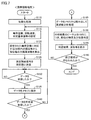
- FIG. 7 is a flowchart showing an example of the processing procedure in the mobile information terminal 30.
- the central processing unit 214 executes a predetermined initialization process (step S110).
- the initialization process for example, communication establishment between the communication unit 204 and the measuring instrument 20 and a predetermined reset process are performed.
- the setting unit 202 determines the vibration state based on the bearing model number of the rolling bearing 15 to be measured, the rotation speed (or rotation frequency) at the time of measurement, and the measurement data.
- the determination reference value and the like are set (step S115). Each of the above setting values is input by the user from the screen of the mobile information terminal 30.
- the central processing unit 214 reads out the specification data of the bearing corresponding to the set bearing model number from the DB unit 208, and from the specification data and the rotation frequency calculated from the set rotation speed, the above Using the formulas (1) to (3), the BPFI, BPFO, and BSF of the rolling bearing 15 to be measured are calculated (step S120). After that, the central processing unit 214 transmits a measurement start signal to the measuring instrument 20 through the communication unit 204 (step S125).
- the central processing unit 214 determines whether or not the measurement data (acceleration data) has been received from the measuring instrument 20 (step S130). Then, when the measurement data is received from the measuring instrument 20 (YES in step S130), the central processing unit 214 stores the received measurement data in a memory (not shown) (step S135).
- the central processing unit 214 determines whether or not the measurement data received from the measuring instrument 20 has reached a predetermined number (step S140), and if the data has not reached the predetermined number (NO in step S140), the step. The processing of S130 and S135 is repeated.
- step S140 When it is determined in step S140 that the number of data has reached a predetermined number (YES in step S140), the central processing unit 214 reads the data from the memory, and the data measured by the analysis unit 206 and the measuring instrument 20 (acceleration). Data) frequency analysis is performed (step S145). Specifically, a fast Fourier transform (FFT) process is performed on the time-series acceleration data measured by the measuring instrument 20, and the frequency spectrum of the measured acceleration data is obtained.
- FFT fast Fourier transform
- the central processing unit 214 extracts the top 10 peak values of the peaks in the obtained frequency spectrum, and identifies the parts corresponding to the peak frequencies of the extracted top 10 peaks. Specifically, the central processing unit 214 determines whether the peak frequency of each of the extracted peaks matches any of BPFI, BPFO, BSF, and their higher-order components, or the rotation frequency of the shaft. Whether the peak is due to an inner ring, an outer ring, a rolling element, an unbalanced shaft, a misalignment, or the like is identified by the frequency of the double frequency and which of the higher-order components thereof is matched. Then, the central processing unit 214 determines the vibration state of each of the specified parts based on the determination reference value set by the determination unit 210 (step S150).
- the determination unit 210 determines that a peak whose peak value exceeds the determination reference value is “dangerous”. Further, the determination unit 210 determines that a peak whose peak value is lower than the determination reference value but exceeds 80% of the determination reference value is "caution”, and a peak whose peak value is lower than 80% of the determination reference value. Judged as "good”.
- the central processing unit 214 uses the display unit 212 to display the determination result, peak value, peak frequency, and portion of step S150 for each of the top 10 peaks of the peak value, together with the waveform of the frequency spectrum of the portable information terminal 30. Display on the screen (step S155).
- the central processing unit 214 determines whether or not the end operation for ending the measurement has been performed by the user (step S160). When it is determined that the end operation has not been performed (NO in step S160), the process is returned to step S115. On the other hand, when it is determined that the end operation has been performed (YES in step S160), the process shifts to the end, and a series of processes in the mobile information terminal 30 are completed.
- the determination results (“danger”, “caution”, and “caution”) of the peak value (acceleration), peak frequency, and vibration state are obtained for the top 10 peaks of the peak value in the frequency spectrum of the measurement data. "Good” etc.), the part (damaged part), etc. are displayed on the screen of the mobile information terminal 30. As a result, the user can easily grasp the magnitude, the portion, and the vibration state of the portion for the peak having a large vibration.
- the number of displayed peaks can be set by the user, so that the display can be realized according to the user's wishes. Further, since the measuring instrument 20 and the mobile information terminal 30 communicate wirelessly, the user can vibrate anywhere within the range where wireless communication is possible as long as the measuring instrument 20 is installed as the measurement target. The analysis result can be confirmed.
- the judgment reference value for judging the vibration state (“danger”, “caution”, “good”, etc.) is set uniformly regardless of the frequency, but in the second embodiment, the judgment reference value is set uniformly.
- Judgment reference value is set for each frequency band. Thereby, the diagnosis is performed for each set frequency band based on an appropriate determination reference value, and it is possible to provide the diagnosis for the frequency band that the user wants to watch.
- the overall configuration of the vibration measurement system according to the second embodiment is the same as that of the first embodiment shown in FIGS. 1 to 3.
- FIG. 8 is a diagram showing an example of the determination reference value in the second embodiment.
- the horizontal axis represents frequency and the vertical axis represents acceleration (vibration).
- the waveform is an example of the result of frequency analysis performed by analysis unit 206.
- 10 frequency bands are set with a constant width from 0, and a judgment reference value is set for each frequency band, but the number of frequency bands is not limited to 10, and each frequency band is not limited to 10.
- the width of the frequency band does not necessarily have to be constant.
- the method for determining the frequency band ⁇ fi may be, for example, to set the width and number of frequency bands with the width of each frequency band constant, or to set the upper limit of the frequency to be analyzed with the number of frequency bands constant. You may set it.
- FIG. 9 is a diagram showing an example of information set by the setting unit 202 in the second embodiment. Also in the second embodiment, the information set by the setting unit 202 can be input by the user from the screen of the mobile information terminal 30, and in FIG. 9, the mobile information terminal 30 for the user to input the information is shown. Screen is shown.
- the bearing model number of the rolling bearing 15 (FIG. 1) to be measured can be input from the input unit 410.
- the rotation speed (min -1 ) of the shaft at the time of measurement can be input.
- the input unit 420 may input the rotation frequency of the shaft at the time of measurement instead of the rotation speed of the shaft at the time of measurement.
- the width of each frequency band can be input when the width of each frequency band is constant for the determination of the vibration state performed based on the judgment reference value set for each frequency band. .. Further, from the input unit 440, when the number of frequency bands is constant, the upper limit of the frequency to be analyzed can be input.
- the user may input either one of the input units 430 and 440, and if there is an input from both the input units 430 and 440, a predetermined value of one (for example, the input unit 430) is adopted. Will be done.
- the number of frequency bands can be input from the input unit 450.
- the frequency bandwidth is set by the input from the input unit 430
- the number of frequency bands having the frequency bandwidth is set by the number input from the input unit 450.
- the upper limit frequency is set by the input from the input unit 440
- the frequency band of the number input from the input unit 450 is set by dividing the upper limit frequency by the number input from the input unit 450. Will be done.
- a judgment reference value can be set for each frequency band.
- the input unit 460 displays each frequency band set from the frequency bandwidth input from the input unit 430 or the upper limit frequency input from the input unit 440 and the number of frequency bands input from the input unit 450. , Judgment reference value is shown for each frequency band.
- the determination reference value shown in the input unit 460 can be moved up and down using an input device (mouse, touch panel, etc.). The user can set the determination reference value for each frequency band in the input unit 460 using the input device.
- FIG. 10 is a flowchart showing an example of the processing procedure in the mobile information terminal 30 of the second embodiment. Also in the second embodiment with reference to FIG. 10 and FIG. 3, application software for performing vibration measurement using the measuring instrument 20 is started on the mobile information terminal 30, and the application software instructs the start of measurement. Then, the central processing unit 214 executes a predetermined initialization process (step S210). This initialization process is the same as the process executed in step S110 of FIG.
- the setting unit 202 sets the bearing model number of the rolling bearing 15 to be measured, the rotation speed (or rotation frequency) at the time of measurement, and the like (step S215). These set values are input by the user from the screen of the mobile information terminal 30.
- the setting unit 202 sets the determination reference value for each frequency band (step S220). As described with reference to FIG. 9, each frequency band is set based on the input values from the input units 430 to 450, and the determination reference value for each frequency band is set based on the input from the input unit 460.
- step S220 When the determination reference value is set for each frequency band in step S220, the process shifts to step S225. Since the processes of steps S225 to S250 are the same as the processes of steps S120 to S145 of FIG. 7, the description will not be repeated.
- the central processing unit 214 sets the determination reference value for each frequency band set in step S220 by the determination unit 210. Based on this, the vibration state of the rolling bearing 15 for each frequency band is determined (step S255).
- the central processing unit 214 identifies a portion corresponding to the peak with respect to the peak whose peak value exceeds the determination reference value (step S260). Specifically, the central processing unit 214 determines whether the peak frequency matches any of BPFI, BPFO, BSF, and their higher-order components for each peak whose peak value exceeds the determination reference value, or the axis. Depending on whether it matches the rotation frequency, twice the frequency, or those higher-order components, which of the defects such as inner ring, outer ring, rolling element, shaft imbalance, and misalignment is the cause of the peak is determined. Identify.
- the central processing unit 214 uses the display unit 212 to display the determination result, peak value, peak frequency, and portion of step S255 for each peak whose peak value exceeds the determination reference value, together with the waveform of the frequency spectrum, of the mobile information terminal 30. Is displayed on the screen of (step S265).
- the central processing unit 214 determines whether or not the end operation for ending the measurement has been performed by the user (step S270). When it is determined that the end operation has not been performed (NO in step S270), the process is returned to step S215. On the other hand, when it is determined that the end operation has been performed (YES in step S270), the process shifts to the end, and a series of processes in the mobile information terminal 30 are completed.
- the determination reference value is set for each frequency band, and the vibration state is determined based on the peak value and the determination reference value of the frequency spectrum in each frequency band.
- the diagnosis is performed based on an appropriate determination reference value for each set frequency band, not for a specific frequency component caused by a bearing abnormality (inner ring, outer ring, rolling element, defect of cage). Therefore, according to the second embodiment, it is possible to provide a diagnostic result for a frequency band that the user wants to pay attention to.
- the measuring instrument 20 and the mobile information terminal 30 are wirelessly communicated with each other, the user can perform wireless communication as long as the measuring instrument 20 is installed as the measurement target. The vibration analysis result can be confirmed regardless of the location within the range.
- the damage frequency for specifying the damaged portion of the bearings is calculated by a predetermined calculation formula using the specification data of the bearings.
- Data regarding the coefficient of the rotation frequency of the bearing (a plurality of constants obtained by dividing the coefficient) is associated with the bearing model number and stored in the DB unit 208. Then, the data corresponding to the bearing model number set by the setting unit 202 is read from the DB unit 208, the damage frequency is calculated based on the read data, and the damaged part is specified.
- the DB unit 208 is the BPFI (Ball Pass Frequency of Inner ring, inner ring passing frequency) and BPFO (Ball Pass Frequency of Outer ring) of the rolling bearing 15 to be measured. , Outer ring passing frequency), and BSF (Ball Spin Frequency, rolling element rotation frequency) are stored in association with the bearing model number.
- the damaged part is specified in the mobile information terminal 30 without using a server. Therefore, it is necessary for the mobile information terminal 30 to have the coefficient of the rotation frequency of the bearing for calculating the BPFI, BPFO, and BSF of the rolling bearing 15 to be measured.
- the BPFI, BPFO, and BSF of the rolling bearing 15 can be calculated using the following equations (7) to (9) from various specifications of the rolling bearing 15 and the rotation frequency f0 of the inner ring shaft of the bearing at the time of measurement. it can.
- D is the pitch circle diameter of the bearing
- d is the diameter of the rolling element
- ⁇ is the contact angle of the rolling element
- Z is the number of rolling elements, and each value corresponds to the specifications of the rolling bearing 15. is there.
- the rotation frequency f0 corresponds to the measurement condition, and is set by the setting unit 202, or is calculated from the set rotation speed when the rotation speed is set by the setting unit 202.
- the coefficients Cin, Cout, and Crol of the rotation frequency f0 are calculated from the specifications of the rolling bearing 15 (bearing pitch circle diameter D, rolling element diameter d, rolling element contact angle ⁇ , number of rolling elements Z).
- the specification data of the rolling bearing 15 (bearing pitch circle diameter D, rolling element diameter d, rolling element contact angle ⁇ , rolling element). It is necessary for the mobile information terminal 30 to have the above coefficients Cin, Cout, and Crol calculated from the number Z) or the specification data.
- each of the coefficients Cin, Cout, and Croll is divided into a plurality of constants and stored in the DB unit 208 of the mobile information terminal 30.
- the coefficients Cin, Cout, and Crol are divided into the constants Ca to Cd represented by the following equations (10) to (12) and stored in the DB unit 208.
- the central processing unit 214 calculates the BPFI, BPFO, and BSF of the rolling bearing 15 at the time of measurement based on the information about the rolling bearing 15 set by the setting unit 202. Specifically, the central processing unit 214 reads out a plurality of constants Ca to Cd corresponding to the bearing model numbers set by the setting unit 202 from the DB unit 208, and the above equation is obtained from the read-out plurality of constants Ca to Cd. The coefficients Cin, Cout, and Crol are restored by (10) to (12). Then, the central processing unit 214 uses the above equations (7) to (9) from the restored coefficients Cin, Cout, and Crol and the rotation speed (or rotation frequency) set by the setting unit 202, and BPFI. , BPFO, BSF are calculated.
- the display unit 212 displays the peak value, the portion, and the determination result (“danger”, “caution”, “good”, etc.) of the determination unit 210 for the peak for which the portion is specified. Display on 30 screens.
- FIG. 11 is a diagram showing an example of information set by the setting unit 202 in the third embodiment.
- the information set by the setting unit 202 can be input by the user from the screen of the mobile information terminal 30, and FIG. 11 shows the screen of the mobile information terminal 30 for the user to input the information. ..
- the bearing model number of the rolling bearing 15 (FIG. 1) to be measured can be input from the input unit 310.
- the rotation speed (min -1 ) of the shaft at the time of measurement can be input. Since the vibration measurement system 10 is not provided with a sensor for detecting the rotation speed of the shaft during measurement by the measuring device 20, it is necessary to obtain information on the rotation speed and input it from the input unit 320 at the time of measurement. However, when the rotation speed sensor is attached, the input unit 320 is unnecessary. Further, the input unit 320 may input the rotation frequency of the shaft at the time of measurement instead of the rotation speed of the shaft at the time of measurement.
- the determination reference value (acceleration) used in the determination unit 210 can be input. Also in the third embodiment, the determination reference value is a uniform value regardless of the peak frequency.
- FIG. 12 is a diagram showing an example of data stored in the DB unit 208 in the third embodiment.
- a plurality of constants Ca to which the coefficients Cin, Cout, and Col for calculating the BPFI, BPFO, and BSF are divided for each bearing whose vibration can be measured by the vibration measurement system 10 Cd is stored according to the bearing model number.
- constants Ca to Cd even if the bearing leaks to the outside of the mobile information terminal 30, it is possible to prevent the specifications of the bearing from being elucidated.
- FIG. 13 is a flowchart showing an example of the processing procedure in the mobile information terminal 30.
- the central processing unit 214 executes a predetermined initialization process (step S310).
- the initialization process for example, communication establishment between the communication unit 204 and the measuring instrument 20 and a predetermined reset process are performed.
- the setting unit 202 determines the vibration state based on the bearing model number of the rolling bearing 15 to be measured, the rotation speed (or rotation frequency) at the time of measurement, and the measurement data.
- the determination reference value and the like are set (step S315). Each of the above setting values is input by the user from the screen of the mobile information terminal 30.
- the central processing unit 214 reads out the bearing constants Ca to Cd (division constants) corresponding to the set bearing model numbers from the DB unit 208, and from the read constants Ca to Cd, the above equations (10) to (10) to ( The coefficients Cin, Cout, and Crol are restored by 12) (step S320).
- the central processing unit 214 uses the above equations (7) to (9) from the restored coefficients Cin, Cout, and Col and the rotation frequency calculated from the rotation speed set in step S315.
- the BPFI, BPFO, and BSF of the rolling bearing 15 to be measured are calculated (step S322).
- the central processing unit 214 transmits a measurement start signal to the measuring instrument 20 through the communication unit 204 (step S325).
- the central processing unit 214 determines whether or not the measurement data (acceleration data) has been received from the measuring instrument 20 (step S330). Then, when the measurement data is received from the measuring instrument 20 (YES in step S330), the central processing unit 214 stores the received measurement data in a memory (not shown) (step S335).
- the central processing unit 214 determines whether or not the measurement data received from the measuring instrument 20 has reached a predetermined number (step S340), and if the data has not reached the predetermined number (NO in step S340), the step. The processing of S330 and S335 is repeated.
- step S340 When it is determined in step S340 that the number of data has reached a predetermined number (YES in step S340), the central processing unit 214 reads the data from the memory, and the data measured by the analysis unit 206 and the measuring instrument 20 (acceleration). Data) frequency analysis is performed (step S345). Specifically, a fast Fourier transform (FFT) process is performed on the time-series acceleration data measured by the measuring instrument 20, and the frequency spectrum of the measured acceleration data is obtained.
- FFT fast Fourier transform
- the central processing unit 214 indicates that the peak frequency of the peak in the obtained frequency spectrum matches any of BPFI, BPFO, BSF, and higher-order components thereof, or the rotation frequency of the axis, which is twice that. Whether the peak is due to defects such as inner ring, outer ring, rolling element, shaft imbalance, misalignment, etc. is identified by the frequency of the frequency and which of these higher-order components is matched. Then, the central processing unit 214 determines the vibration state of each of the specified parts by the determination unit 210 based on the judgment reference value set in step S315 (step S350).
- the determination unit 210 determines that a peak whose peak value exceeds the determination reference value is “dangerous”. Further, the determination unit 210 determines that a peak whose peak value is lower than the determination reference value but exceeds 80% of the determination reference value is "caution”, and a peak whose peak value is lower than 80% of the determination reference value. Judged as "good”.
- the central processing unit 214 displays the determination result, peak value, peak frequency, and portion of step S350 on the screen of the mobile information terminal 30 together with the waveform of the frequency spectrum by the display unit 212 (step S355).
- the central processing unit 214 determines whether or not the end operation for ending the measurement has been performed by the user (step S360). When it is determined that the end operation has not been performed (NO in step S360), the process is returned to step S315. On the other hand, when it is determined that the end operation has been performed (YES in step S360), the process shifts to the end, and a series of processes in the mobile information terminal 30 are completed.
- the coefficients Cin, Cout, and Crol for calculating the BPFI, BPFO, and BSF are divided into a plurality of constants Ca to Cd and stored in the DB unit 208. Then, when the vibration analysis is executed, the constants Ca to Cd are read from the DB unit 208, the coefficients Cin, Cout, and Crol are restored, and the restored coefficients Cin, Cout, and Crol are used to calculate BPFI, BPFO, and BSF. Will be done.
- the data (constants Ca to Cd) stored in the DB unit 208 leaks to the outside of the mobile information terminal 30, the specifications of the bearing that can be measured by the vibration measurement system 10 will be clarified. Can be prevented. Therefore, according to the third embodiment, it is possible to prevent leakage of bearing specification data.
- the measuring instrument 20 and the mobile information terminal 30 are wirelessly communicated with each other, the user can perform wireless communication as long as the measuring instrument 20 is installed as the measurement target. The vibration analysis result can be confirmed regardless of the location within the range.
- each of the coefficients Cin, Cout, and Crol used for calculating the BPFI, BPFO, and BSF is divided into a plurality of constants Ca to Cd and stored in the DB unit 208.
- the specification data of the rolling bearing 15 to be measured (bearing pitch circle diameter D, rolling element diameter d, rolling element contact angle ⁇ , number of rolling elements Z, etc.) are encrypted and the DB unit is used.
- the encrypted specification data is read from the DB unit 208 and decrypted, and BPFI, BPFO, and BSF are calculated.
- the overall configuration of the vibration measurement system according to the fourth embodiment is the same as that of the first embodiment shown in FIGS. 1 and 2.
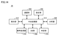
- FIG. 14 is a diagram showing the configuration of the mobile information terminal 30 according to the fourth embodiment.
- the mobile information terminal 30 according to the fourth embodiment further includes an encryption processing unit 216 in the mobile information terminal 30 according to the first embodiment shown in FIG.
- the specification data encrypted according to a predetermined encryption method is stored in the DB unit 208 in association with the bearing model number for various bearings whose vibration can be measured by the vibration measurement system 10.
- the encryption method may be a common key cryptosystem or a public key cryptosystem. Further, the encryption may be performed using the same key encryption for each specification, or may be performed using a different key encryption for each specification. Various known methods can be used as the encryption method.
- the encryption processing unit 216 reads the specification data (encrypted data) corresponding to the bearing model number set by the setting unit 202 from the DB unit 208 according to the instruction from the central processing unit 214, and performs the key encryption according to the encryption method. It is used to decode the read specification data.
- the central processing unit 214 uses the above equations (7) to (9) from the specification data decrypted by the encryption processing unit 216 and the rotation speed (or rotation frequency) set by the setting unit 202, and BPFI. , BPFO, BSF are calculated.
- the processing of the central processing unit 214 after calculating the BPFI, BPFO, and BSF is the same as that of the third embodiment.
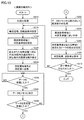
- FIG. 15 is a flowchart showing an example of the processing procedure in the mobile information terminal 30 of the fourth embodiment.
- application software for performing vibration measurement using the measuring instrument 20 is started on the mobile information terminal 30, and the application software instructs the start of measurement.
- the central processing unit 214 executes a predetermined initialization process (step S410).
- the setting unit 202 sets the bearing model number of the rolling bearing 15 to be measured, the rotation speed (or rotation frequency) at the time of measurement, the determination reference value for determining the vibration state based on the measurement data, and the like ( Step S415).
- the process executed in steps S410 and S415 is the same as the process executed in steps S310 and S315 of FIG.
- the specification data (encrypted data) of the bearing corresponding to the set bearing model number was read from the DB unit 208 and encrypted by the encryption processing unit 216 using a key encryption according to a predetermined encryption method.
- the specification data is decrypted (step S420).
- the central processing unit 214 uses the above equations (7) to (9) to measure the height from the decoded specification data and the rotation frequency calculated from the rotation speed set in step S415.
- the BPFI, BPFO, and BSF of a certain rolling bearing 15 are calculated (step S422).
- step S422 When BPFI, BPFO, and BSF are calculated in step S422, the process shifts to step S425. Since the processes of steps S425 to S455 are the same as the processes of steps S325 to S355 of FIG. 13, the description will not be repeated.
- step S460 determines whether or not the end operation for ending the measurement has been performed by the user.
- the process is returned to step S415.
- the process shifts to the end, and a series of processes in the mobile information terminal 30 are completed.
- the specification data of the rolling bearing 15 to be measured is encrypted and stored in the DB unit 208. Then, when the vibration analysis is executed, the encrypted specification data is read from the DB unit 208 and decoded, and the BPFI, BPFO, and BSF are calculated using the decoded specification data. As a result, if the data (encrypted specification data) stored in the DB unit 208 leaks to the outside of the mobile information terminal 30, the specifications of the bearing that can be measured by the vibration measuring system 10 are clarified. Can be prevented. Therefore, even according to the fourth embodiment, leakage of bearing specification data can be prevented.
- the measuring instrument 20 and the mobile information terminal 30 are wirelessly communicated with each other, the user can perform wireless communication as long as the measuring instrument 20 is installed as the measurement target. The vibration analysis result can be confirmed regardless of the location within the range.
- the specification data to be measured is encrypted and stored in the DB unit 208, but the coefficients Cin, Cout, and Crol for calculating the BPFI, BPFO, and BSF are assumed. May be encrypted and stored in the DB unit 208, or a plurality of constants Ca to Cd obtained by dividing the coefficients Cin, Cout, and Crol described in the third embodiment may be encrypted and stored in the DB unit 208. Good.
- a plurality of constants Ca to Cd may be stored in the DB unit 208 in a binary format. This also makes it possible to prevent the specifications of the bearings measurable by the vibration measuring system 10 from being clarified if the data stored in the DB unit 208 leaks to the outside of the mobile information terminal 30.
- the specification data in the binary format may be encrypted and stored in the DB unit 208.
- the coefficients Cin, Cout, Crol in the binary format, or a plurality of constants Ca to Cd in the binary format may be encrypted and stored in the DB unit 208.
- the measuring instrument 20 and the mobile information terminal 30 are wirelessly communicated with each other.
- the measuring instrument 20 and the mobile information terminal 30 are connected to each other. It may be connected by the communication line 40 and communicate between the measuring instrument 20 and the mobile information terminal 30 through the communication line 40.
- Vibration measurement system 15 Measurement target (rolling bearing), 20 Measuring instrument, 30 Mobile information terminal, 40 Communication line, 102 Accelerometer, 104 Anti-aliasing filter, 106 A / D converter, 108 Microcomputer, 110 Memory, 112 Communication module, 202 setting unit, 204 communication unit, 206 analysis unit, 208 DB unit, 210 judgment unit, 212 display unit, 214 central processing unit, 216 encryption processing unit, 310 to 340, 410 to 460 input unit.
Landscapes
- Physics & Mathematics (AREA)
- General Physics & Mathematics (AREA)
- Acoustics & Sound (AREA)
- Engineering & Computer Science (AREA)
- Computer Networks & Wireless Communication (AREA)
- Measurement Of Mechanical Vibrations Or Ultrasonic Waves (AREA)
- Testing Of Devices, Machine Parts, Or Other Structures Thereof (AREA)
Abstract
中央処理部(214)は、周波数分析により得られる周波数スペクトルにおいてピーク値の上位10位のピークについて、測定対象の軸受に関する情報に基づいて部位を特定する。判定部(210)は、ピーク値の上位10位のピークについて、ピーク値及び判定基準値に基づいて振動状態を判定する。表示部(212)は、ピーク値の上位10位のピークについて、ピーク値、部位、及び判定部(210)の判定結果を表示する。
Description
本発明は、振動解析装置及び振動測定システムに関し、特に、測定対象である回転体の振動を測定する測定器から測定データを受信して振動解析を行なう振動解析装置、及びそれを備える振動測定システムに関する。
特開2016-24007号公報(特許文献1)は、転がり軸受等の診断システムを開示する。この診断システムでは、情報端末器は、振動センサから入力された測定データと、診断対象物の型番と、測定時の回転速度のデータとをサーバへ送信する。サーバは、測定データから転がり軸受等の異常を診断し、診断結果を情報端末器へ返送する。また、サーバは、型番毎の診断対象物の諸元データ(仕様データ)を保有しており、受信した測定データを、受信した型番に対応する諸元データと、受信した回転速度のデータとを用いて処理し、診断結果を情報端末器へ返送する。そして、情報端末器は、サーバから返送された診断結果を表示する(特許文献1参照)。
また、米国特許第7587299号明細書(特許文献2)は、機械設備に用いられる軸受の異常診断方法を開示する。この異常診断方法では、軸受の異常によって生じる周波数成分のみが抽出される。具体的には、内輪欠陥成分、外輪欠陥成分、転動体欠陥成分、及び保持器成分の周波数が抽出される。これらの周波数成分は、内輪回転速度、転動体直径、ピッチ円直径、転動体数、及び接触角に基づいて計算される。そして、抽出された周波数成分の大きさに基づいて異常診断が行なわれる(特許文献2参照)。
特許文献1に記載の診断システムでは、サーバにおいて診断が行なわれ、サーバから返送された診断結果が情報端末器に表示されるので、ユーザは、情報端末器で診断結果を確認することができる。一方、診断結果を情報端末器にどのように表示するかについては、特許文献1では特に検討されていない。情報端末器を利用するユーザに診断結果を分かりやすく表示することは、このような診断システムの利便性向上に資する。
特許文献2に記載の異常診断方法は、軸受の異常によって生じる周波数成分のみ(内輪欠陥成分、外輪欠陥成分、転動体欠陥成分、及び保持器成分)について異常診断を行なうものであるため、ミスアライメントや軸のアンバランス等その他の異常については、診断は行なわれない。ユーザによっては、軸受の異常によって生じる特定の周波数成分ではなく、ユーザが注視したい周波数帯域についての診断を希望することも想定される。
それゆえに、本発明の目的は、測定対象である回転体の振動を測定する測定器から測定データを受信して振動解析を行なう振動解析装置において、振動解析の結果を分かりやすく表示することである。
また、本発明の他の目的は、測定対象である回転体の振動を測定する測定器から測定データを受信して振動解析を行なう振動解析装置において、ユーザが注視したい周波数帯域についての診断結果を提供可能とすることである。
また、特許文献1に記載の診断システムでは、サーバにおいて診断が行なわれるので、情報端末器とサーバとの間でデータの転送を行なう必要がある。そのため、ネットワーク環境を整備する必要がある。また、通信状況によっては、データ転送に時間を要し、診断結果が情報端末器に表示されるまでに時間がかかる可能性がある。
そこで、サーバを用いずに、情報端末器において診断を行なうことが考えられる。情報端末器において診断を行なうには、測定対象の諸元データ、又は諸元データから所定の演算式を用いて算出される係数データ(具体的には、測定対象の損傷部位に応じて周期的に発生する振動の周波数を示す損傷周波数を算出するための、測定対象の回転周波数の係数であって、測定対象の回転周波数が単位周波数であるときの損傷周波数に相当)を情報端末器が保有する必要がある。この場合、測定対象の諸元は、メーカのノウハウが詰まったものであるため、諸元データ、又は諸元データから算出される上記係数データの漏洩防止に十分に配慮する必要がある。
それゆえに、本発明の他の目的は、測定対象である回転体の振動を測定する測定器から測定データを受信して振動解析を行なう振動解析装置において、測定対象の諸元データ、又は諸元データから算出される係数データの漏洩を防止することである。
本発明のある局面に従う振動解析装置は、測定対象である回転体の振動を測定する測定器から測定データを受信して振動解析を行なう振動解析装置であって、設定部と、分析部と、処理部と、判定部と、表示部とを備える。設定部は、回転体に関する情報、及び回転体の振動状態を診断するための判定基準値を設定する。分析部は、測定器から受信した測定データの周波数分析を実行する。処理部は、周波数分析により得られる周波数スペクトルにおいてピーク値の大きい方から所定数のピークについて、回転体に関する情報に基づいて部位を特定する。判定部は、所定数のピークについて、ピーク値及び判定基準値に基づいて振動状態を判定する。表示部は、所定数のピークについて、ピーク値、部位、及び判定部の判定結果を表示する。
この振動解析装置においては、周波数分析により得られる周波数スペクトルにおいてピーク値の大きい方から所定数のピークについて、ピーク値、部位、及び判定部の判定結果が表示される。これにより、ユーザは、注視すべきポイントを表示結果から探したり、周波数スペクトルのグラフから値を読み取ったりする必要はなく、振動の大きいピークについて、振動の大きさ、部位、当該部位の振動状態(たとえば、危険レベル、注意レベル、良好レベル等)を容易に把握することができる。
好ましくは、所定数は、振動解析装置を利用するユーザにより設定される。
また、本発明の他の局面に従う振動解析装置は、測定対象である回転体の振動を測定する測定器から測定データを受信して振動解析を行なう振動解析装置であって、設定部と、分析部と、判定部とを備える。設定部は、回転体に関する情報、振動解析を行なう複数の周波数帯域、及び複数の周波数帯域に対応して設けられる複数の判定基準値を設定する。分析部は、測定器から受信した測定データの周波数分析を実行する。判定部は、複数の周波数帯域の各々において、周波数分析により得られる周波数スペクトルのピーク値と、当該周波数帯域に対応する判定基準値とに基づいて、当該周波数帯域における振動状態を判定する。
また、本発明の他の局面に従う振動解析装置は、測定対象である回転体の振動を測定する測定器から測定データを受信して振動解析を行なう振動解析装置であって、設定部と、分析部と、判定部とを備える。設定部は、回転体に関する情報、振動解析を行なう複数の周波数帯域、及び複数の周波数帯域に対応して設けられる複数の判定基準値を設定する。分析部は、測定器から受信した測定データの周波数分析を実行する。判定部は、複数の周波数帯域の各々において、周波数分析により得られる周波数スペクトルのピーク値と、当該周波数帯域に対応する判定基準値とに基づいて、当該周波数帯域における振動状態を判定する。
この振動解析装置においては、振動状態を診断するための判定基準値が周波数帯域毎に設定され、各周波数帯域において、周波数スペクトルのピーク値と、当該周波数帯域に対応する判定基準値とに基づいて、当該周波数帯域における振動状態が判定される。これにより、軸受の異常(内輪、外輪、転動体、保持器の欠陥)によって生じる特定の周波数成分ではなく、設定された周波数帯域毎に、適切な判定基準値に基づいて診断が行なわれる。したがって、この振動解析装置によれば、ユーザが注視したい周波数帯域についての診断結果を提供することができる。
好ましくは、複数の周波数帯域は、振動解析装置を利用するユーザにより設定される。
また、本発明の他の局面に従う振動解析装置は、測定対象である回転体の振動を測定する測定器から測定データを受信して振動解析を行なう振動解析装置であって、データベース部と、処理部とを備える。データベース部は、回転体の損傷部位に応じて周期的に発生する振動の周波数を示す損傷周波数を算出するための、回転体の回転周波数の係数を、複数の定数に分割して記憶する。処理部は、振動解析の実行時に、データベース部から複数の定数を読み出して回転周波数の係数を復元し、その復元された係数を用いて損傷周波数を算出する。
また、本発明の他の局面に従う振動解析装置は、測定対象である回転体の振動を測定する測定器から測定データを受信して振動解析を行なう振動解析装置であって、データベース部と、処理部とを備える。データベース部は、回転体の損傷部位に応じて周期的に発生する振動の周波数を示す損傷周波数を算出するための、回転体の回転周波数の係数を、複数の定数に分割して記憶する。処理部は、振動解析の実行時に、データベース部から複数の定数を読み出して回転周波数の係数を復元し、その復元された係数を用いて損傷周波数を算出する。
回転体の損傷周波数を算出するための、回転体の回転周波数の係数は、回転体の諸元の情報を含むものであるところ、この振動解析装置においては、当該係数が、複数の定数に分割されてデータベース部に記憶されている。そして、振動解析の実行時に、データベース部から複数の定数が読み出されて回転周波数の係数が復元され、復元された係数を用いて損傷周波数が算出される。これにより、データベース部に記憶されているデータが仮に外部に漏洩した場合に、回転体の諸元が解明されるのを防止することができる。したがって、この振動解析装置によれば、測定対象である回転体の諸元データの漏洩を防止することができる。
好ましくは、データベース部は、上記の複数の定数を暗号化した暗号化データを記憶する。処理部は、データベース部から暗号化データを読み出して復号し、復号された複数の定数から係数を復元する。
好ましくは、データベース部は、複数の定数をバイナリ形式で記憶する。
また、本発明の他の局面に従う振動解析装置は、測定対象である回転体の振動を測定する測定器から測定データを受信して振動解析を行なう振動解析装置であって、データベース部と、処理部とを備える。データベース部は、回転体の諸元データを暗号化した暗号化データを記憶する。処理部は、振動解析の実行時に、データベース部から暗号化データを読み出して復号し、復号された諸元データを用いて、回転体の損傷部位に応じて周期的に発生する振動の周波数を示す損傷周波数を算出する。
また、本発明の他の局面に従う振動解析装置は、測定対象である回転体の振動を測定する測定器から測定データを受信して振動解析を行なう振動解析装置であって、データベース部と、処理部とを備える。データベース部は、回転体の諸元データを暗号化した暗号化データを記憶する。処理部は、振動解析の実行時に、データベース部から暗号化データを読み出して復号し、復号された諸元データを用いて、回転体の損傷部位に応じて周期的に発生する振動の周波数を示す損傷周波数を算出する。
この振動解析装置においては、損傷周波数の算出に用いられる回転体の諸元データは、暗号化されてデータベース部に記憶されている。そして、振動解析の実行時に、データベース部から暗号化データが読み出されて復号され、復号された諸元データを用いて、回転体の損傷部位に応じて周期的に発生する振動の周波数を示す損傷周波数が算出される。これにより、データベース部に記憶されているデータが仮に外部に漏洩した場合に、回転体の諸元が解明されるのを防止することができる。したがって、この振動解析装置によれば、測定対象である回転体の諸元データの漏洩を防止することができる。
好ましくは、データベース部は、バイナリ形式の諸元データを暗号化した暗号化データを記憶する。
好ましくは、回転体は、軸受である。
好ましくは、回転体に関する情報は、(i)軸受の回転速度又は回転周波数と、(ii)軸受の諸元、又は軸受のBPFI(Ball Pass Frequency of Inner ring、内輪通過周波数)、BPFO(Ball Pass Frequency of Outer ring、外輪通過周波数)、及びBSF(Ball Spin Frequency、転動体回転周波数)の算出に用いられる回転周波数の係数とを含む。
好ましくは、回転体に関する情報は、(i)軸受の回転速度又は回転周波数と、(ii)軸受の諸元、又は軸受のBPFI(Ball Pass Frequency of Inner ring、内輪通過周波数)、BPFO(Ball Pass Frequency of Outer ring、外輪通過周波数)、及びBSF(Ball Spin Frequency、転動体回転周波数)の算出に用いられる回転周波数の係数とを含む。
好ましくは、振動解析装置は、測定器と無線通信を行なう通信部をさらに備える。
また、本発明の振動測定システムは、測定対象である回転体の振動を測定する測定器と、測定器から測定データを受信して振動解析を行なう上記の振動解析装置とを備える。
また、本発明の振動測定システムは、測定対象である回転体の振動を測定する測定器と、測定器から測定データを受信して振動解析を行なう上記の振動解析装置とを備える。
本発明によれば、測定対象である回転体の振動を測定する測定器から測定データを受信して振動解析を行なう振動解析装置において、振動解析の結果を分かりやすく表示することができる。
また、本発明によれば、測定対象である回転体の振動を測定する測定器から測定データを受信して振動解析を行なう振動解析装置において、ユーザが注視したい周波数帯域についての診断結果を提供することができる。
また、本発明によれば、測定対象である回転体の振動を測定する測定器から測定データを受信して振動解析を行なう振動解析装置において、測定対象の諸元データの漏洩を防止することができる。
以下、本発明の実施の形態について、図面を参照しながら詳細に説明する。以下では、複数の実施の形態について説明するが、各実施の形態で説明された構成を適宜組合わせることは出願当初から予定されている。なお、図中同一又は相当部分には同一符号を付してその説明は繰り返さない。
[実施の形態1]
図1は、本発明の実施の形態1に従う振動測定システムを示す図である。図1を参照して、振動測定システム10は、測定器20と、携帯情報端末30とを備える。
図1は、本発明の実施の形態1に従う振動測定システムを示す図である。図1を参照して、振動測定システム10は、測定器20と、携帯情報端末30とを備える。
測定器20は、測定対象である転がり軸受15に生じる振動を測定するための機器であり、振動を検出するための加速度センサ(図示せず)を含んで構成される。測定器20は、携帯情報端末30と無線通信可能に構成されており、携帯情報端末30から測定開始信号を受信すると、転がり軸受15に生じる振動を加速度センサによって検出する。そして、測定器20は、加速度センサにより検出された加速度データを携帯情報端末30へ送信する。
携帯情報端末30は、本発明における「振動解析装置」であり、測定器20から測定データ(振動の加速度データ)を受信して、転がり軸受15に生じている振動の解析を行なう。携帯情報端末30は、振動測定システム10を利用するユーザが利用可能な端末であり、たとえばスマートフォンやタブレット等である。携帯情報端末30上で動作するアプリケーションソフトによって、携帯情報端末30を「振動解析装置」として用いることができる。
図2は、測定器20の構成を示す図である。図2を参照して、測定器20は、加速度センサ102と、アンチエイリアシングフィルタ104と、A/D変換器106と、マイクロコンピュータ108と、メモリ110と、通信モジュール112とを含む。
加速度センサ102は、測定対象である転がり軸受15(図1)を内蔵するハウジング等に取り付けられ、転がり軸受15に生じる振動の加速度を検出して出力する。アンチエイリアシングフィルタ104は、A/D変換器106におけるA/D変換時に発生するエイリアシング誤差を抑制するためのローパスフィルタである。A/D変換器106は、アンチエイリアシングフィルタ104を通過した測定信号(アナログ信号)をデジタル信号に変換する。
マイクロコンピュータ108は、A/D変換器106によりデジタル信号に変換された加速度データを受け、メモリ110へ出力する。そして、所定量のデータがメモリ110に蓄積されると、マイクロコンピュータ108は、蓄積されたデータをメモリ110から読み出して、測定器20による測定データとして通信モジュール112により携帯情報端末30へ送信する。
メモリ110は、A/D変換器106によりデジタル信号に変換された加速度データをマイクロコンピュータ108から受けて一時的に記憶する。通信モジュール112は、測定器20が携帯情報端末30と無線通信を行なうための無線モジュールである。
図3は、携帯情報端末30の構成を示す図である。図3を参照して、携帯情報端末30は、設定部202と、通信部204と、分析部206と、データベース(DB)部208と、判定部210と、表示部212と、中央処理部214とを含む。
設定部202は、測定対象である転がり軸受15(図1)に関する情報を設定する。本実施の形態1では、設定される情報は、携帯情報端末30の画面からユーザにより入力されるものとするが、予めDB部208に記憶しておいて、振動測定システム10による振動測定の開始時にDB部208から読み出してもよい。転がり軸受15に関する情報は、転がり軸受15の軸受型番、測定器20による測定時の転がり軸受15の回転速度又は回転周波数等である。
なお、本実施の形態1では、振動測定システム10により振動測定可能な各種軸受の諸元データが軸受型番に対応付けられてDB部208に予め格納されている。そして、設定部202により設定される軸受型番の軸受の諸元データがDB部208から読み出されるものとしているが、設定部202により、転がり軸受15に関する情報として、転がり軸受15の諸元データを直接設定してもよい。
また、設定部202は、判定部210において測定対象である転がり軸受15の振動状態を判定するための判定基準値をさらに設定する。この判定基準値についても、本実施の形態1では、携帯情報端末30の画面からユーザにより入力されるものとするが、予めDB部208に記憶しておいて、振動測定システム10による振動測定の開始時にDB部208から読み出してもよい。
通信部204は、携帯情報端末30が測定器20と無線通信を行なうためのユニットであり、無線モジュールによって構成される。通信部204は、中央処理部214からの指示に従って、振動測定システム10による振動測定の開始時に測定開始信号を測定器20へ送信する。また、通信部204は、測定器20から送信されてくる測定データ(加速度データ)を受信する。
分析部206は、通信部204により受信した測定データ(加速度データ)の周波数分析を実行する。一例として、分析部206は、通信部204により受信した時系列の加速度データに対して高速フーリエ変換(FFT)処理を行ない、測定データ(加速度データ)の周波数スペクトルを生成する。
DB部208は、この振動測定システム10により振動測定可能な各種軸受の諸元データを軸受型番に対応付けて記憶している。本実施の形態1では、諸元データは、以下の式(1)~(3)に示すBPFI(内輪通過周波数)、BPFO(外輪通過周波数)、BSF(転動体回転周波数)を算出可能なデータを少なくとも含む。

ここで、Dは軸受のピッチ円直径、dは転動体の直径、αは転動体の接触角、Zは転動体の数を示す。なお、f0は内輪軸の回転周波数を示し、設定部202により設定されるか、設定部202により回転速度が設定される場合には、その回転速度から算出される。
DB部208は、少なくとも、上記のピッチ円直径D、転動体の直径d、転動体の接触角α、転動体の数Zの諸元データを軸受型番に対応付けて記憶している。なお、これらの諸元データに代えて、BPFI、BPFO、BSFをそれぞれ算出するための、回転周波数f0の係数Cin,Cout,CrolをDB部208に記憶しておいてもよい。係数Cin,Cout,Crolは、以下の式(4)~(6)によって示される。

中央処理部214は、設定部202により設定された、転がり軸受15に関する情報に基づいて、測定時における転がり軸受15のBPFI、BPFO、BSFを算出する。具体的には、中央処理部214は、設定部202により設定された軸受型番に対応する軸受の諸元データをDB部208から読み出し、読み出された諸元データと、設定部202により設定された回転速度(又は回転周波数)とから、上記の式(1)~(3)を用いてBPFI、BPFO、BSFを算出する。
また、中央処理部214は、分析部206により得られる加速度データの周波数スペクトルにおけるピークについて、ピーク毎に部位を特定する。より詳しくは、ピークの周波数(以下「ピーク周波数」と称する。)がBPFI及びその高次成分と一致するピークについては、内輪に欠陥が生じているものと特定される。また、ピーク周波数がBPFO及びその高次成分と一致するピークについては、外輪に欠陥が生じているものと特定され、ピーク周波数がBSF及びその高次成分と一致するピークについては、転動体に欠陥が生じているものと特定される。
また、ピーク周波数が軸の回転周波数及びその高次成分と一致するピークについては、軸のアンバランスが生じているものと特定され、ピーク周波数が回転周波数の2倍の周波数及びその高次成分と一致するピークについては、ミスアライメントが生じているものと特定される。このように、本実施の形態1では、ピークに対応する部位について、BPFI、BPFO、BSFに対応する軸受の部位(内輪、外輪、転動体)だけでなく、軸のアンバランスやミスアライメント等の軸受そのもの以外の部位も特定される。
判定部210は、ピーク周波数のピーク値(加速度)、及び設定部202により設定された判定基準値に基づいて、ピーク毎に振動状態を判定する。たとえば、判定部210は、ピーク値が判定基準値を超えるピークについては「危険」と判定する。また、判定部210は、たとえば、ピーク値が判定基準値よりも低いけれども判定基準値の8割を超えるピークについては「注意」と判定し、ピーク値が判定基準値の8割よりも低いピークについては「良好」と判定する。
表示部212は、ピーク値の上位10位のピークについて、ピーク値、部位、及び判定部210の判定結果(「危険」「注意」「良好」等)を携帯情報端末30の画面に表示する。なお、表示されるピークの数は、10個に限られるものではなく、その他の数でもよいし、デフォルトで10としつつ、携帯情報端末30の画面からユーザが設定可能としてもよい。
なお、この実施の形態1では、表示部212により表示されるピーク数に従って、中央処理部214は、ピーク値の上位10位のピークについて部位を特定し、判定部210は、ピーク値の上位10位のピークについて振動状態を判定するものとするが、中央処理部214は、特定される全てのピークについて部位を特定してもよく、判定部210は、特定される全てのピークについて振動状態を判定してもよい。
図4は、表示部212による表示例を示す図である。この図4には、表示部212による表示情報が表示された携帯情報端末30の画面が示されている。
図4を参照して、この例では、ピーク値の上位10位のピークについて、ピーク値(加速度)、ピーク周波数、判定部210の判定結果、部位(損傷箇所)が、ピーク値(加速度)の大きい順(a1>a2>・・・>a10)に表示される。なお、表示されるピークについては、高次成分のピークも含まれている(「回転2次」「外輪2次」等)。
なお、この例では、ピーク値の大きい順に表示されているが、周波数の小さい順(f1<f2<・・・<f10)に表示する等してもよい。また、判定結果に応じて色分け表示(たとえば、「危険」は赤色、「注意」は黄色、「良好」は緑色)する等してもよい。
図5は、設定部202により設定される情報の一例を示す図である。設定部202により設定される情報は、携帯情報端末30の画面からユーザが入力可能であり、この図5には、当該情報をユーザが入力するための携帯情報端末30の画面が示されている。
図5を参照して、入力部310からは、測定対象である転がり軸受15(図1)の軸受型番を入力することができる。
入力部320からは、測定時の軸の回転速度(min-1)を入力することができる。なお、この振動測定システム10では、測定器20による測定時の軸の回転速度を検出するセンサは設けられていないため、測定に際し回転速度の情報を入手して入力部320から入力する必要があるが、回転速度センサが付属している場合には、入力部320は不要である。また、入力部320において、測定時の軸の回転速度に代えて、測定時の軸の回転周波数を入力するようにしてもよい。
入力部330からは、判定部210において用いられる判定基準値(加速度)を入力することができる。なお、本実施の形態1では、判定基準値は、ピーク周波数に拘わらず一律の値としている。
入力部340からは、表示部212により表示されるピーク値上位の表示点数を入力することができる。この入力値に従って、表示部212により表示されるピークの数が設定される。なお、入力部340からの入力がない場合は、デフォルト値(たとえば10)が設定される。
図6は、測定器20における処理の手順の一例を示すフローチャートである。図6とともに図2を参照して、測定器20の電源がオンされると、マイクロコンピュータ108は、所定の初期化処理を実行する(ステップS10)。初期化処理では、たとえば、通信モジュール112と携帯情報端末30との間の通信確立や、メモリ110のデータクリア等が行なわれる。
次いで、マイクロコンピュータ108は、携帯情報端末30から測定開始信号を受信したか否かを判定する(ステップS20)。そして、測定開始信号が受信されると(ステップS20においてYES)、マイクロコンピュータ108は、アンチエイリアシングフィルタ104を通過し、かつ、A/D変換器106によりデジタル変換された加速度センサ102の出力をA/D変換器106から読み込む(ステップS30)。
マイクロコンピュータ108は、A/D変換器106から読み込んだデータをメモリ110に一時的に保存する(ステップS40)。そして、マイクロコンピュータ108は、取得されたデータが所定数に達したか否かを判定し(ステップS50)、取得データが所定数に達していなければ(ステップS50においてNO)、ステップS30,S40の処理を繰り返す。
ステップS50において取得データが所定数に達したと判定されると(ステップS50においてYES)、マイクロコンピュータ108は、取得データをメモリ110から読み出して、通信モジュール112により携帯情報端末30へデータを送信する(ステップS60)。
次いで、マイクロコンピュータ108は、測定を終了する終了操作がユーザにより行なわれたか否かを判定する(ステップS70)。なお、終了操作は、携帯情報端末30において行なわれ、たとえば、携帯情報端末30から測定終了信号を受信すると、終了操作が行なわれたものと判定される。
終了操作が行なわれていないと判定されたときは(ステップS70においてNO)、ステップS20へ処理が戻される。一方、終了操作が行なわれたと判定されると(ステップS70においてYES)、エンドへ処理が移行して、測定器20における一連の処理が終了する。
図7は、携帯情報端末30における処理の手順の一例を示すフローチャートである。図7とともに図3を参照して、測定器20を用いた振動測定を行なうためのアプリケーションソフトが携帯情報端末30上で起動され、当該アプリケーションソフトにおいて測定の開始が指示されると、中央処理部214は、所定の初期化処理を実行する(ステップS110)。初期化処理では、たとえば、通信部204と測定器20との間の通信確立や、所定のリセット処理等が行なわれる。
次いで、中央処理部214からの指示に従って、設定部202により、測定対象である転がり軸受15の軸受型番、測定時の回転速度(又は回転周波数)、測定データに基づいて振動状態を判定するための判定基準値等が設定される(ステップS115)。上記の各設定値は、携帯情報端末30の画面からユーザにより入力される。
次いで、中央処理部214は、設定された軸受型番に対応する軸受の諸元データをDB部208から読み出し、その諸元データと、設定された回転速度から算出される回転周波数とから、上記の式(1)~(3)を用いて、測定対象の転がり軸受15のBPFI、BPFO、BSFを算出する(ステップS120)。その後、中央処理部214は、通信部204を通じて測定器20へ測定開始信号を送信する(ステップS125)。
測定開始信号が測定器20へ送信されると、中央処理部214は、測定器20から測定データ(加速度データ)を受信したか否かを判定する(ステップS130)。そして、測定器20から測定データが受信されると(ステップS130においてYES)、中央処理部214は、受信された測定データをメモリ(図示せず)に保存する(ステップS135)。
次いで、中央処理部214は、測定器20から受信した測定データが所定数に達したか否かを判定し(ステップS140)、データが所定数に達していなければ(ステップS140においてNO)、ステップS130,S135の処理を繰り返す。
ステップS140においてデータが所定数に達したと判定されると(ステップS140においてYES)、中央処理部214は、メモリからデータを読み出して、分析部206により、測定器20により測定されたデータ(加速度データ)の周波数分析を実行する(ステップS145)。具体的には、測定器20により測定された時系列の加速度データに対して高速フーリエ変換(FFT)処理が行なわれ、測定された加速度データの周波数スペクトルが得られる。
次いで、中央処理部214は、得られた周波数スペクトルにおけるピークについて、ピーク値の上位10位を抽出し、その抽出された上位10位のピークについて、ピーク周波数に対応する部位を特定する。具体的には、中央処理部214は、抽出されたピークの各々について、ピーク周波数が、BPFI、BPFO、BSF、及びそれらの高次成分のいずれと一致するか、或いは、軸の回転周波数、その2倍の周波数、及びそれらの高次成分のいずれと一致するかによって、当該ピークが、内輪、外輪、転動体、軸のアンバランス、ミスアライメント等のいずれの欠陥によるものかを特定する。そして、中央処理部214は、特定された各部位について、判定部210により、設定された判定基準値に基づいて、各部位の振動状態を判定する(ステップS150)。
たとえば、判定部210は、ピーク値が判定基準値を超えるピークについては「危険」と判定する。また、判定部210は、ピーク値が判定基準値よりも低いけれども判定基準値の8割を超えるピークについては「注意」と判定し、ピーク値が判定基準値の8割よりも低いピークについては「良好」と判定する。
そして、中央処理部214は、表示部212により、ピーク値の上位10位の各ピークについて、ステップS150の判定結果、ピーク値、ピーク周波数、及び部位を、周波数スペクトルの波形とともに携帯情報端末30の画面に表示する(ステップS155)。
次いで、中央処理部214は、測定を終了する終了操作がユーザにより行なわれたか否かを判定する(ステップS160)。終了操作が行なわれていないと判定されたときは(ステップS160においてNO)、ステップS115へ処理が戻される。一方、終了操作が行なわれたと判定されると(ステップS160においてYES)、エンドへ処理が移行して、携帯情報端末30における一連の処理が終了する。
以上のように、この実施の形態1では、測定データの周波数スペクトルにおいてピーク値の上位10位のピークについて、ピーク値(加速度)、ピーク周波数、振動状態の判定結果(「危険」「注意」「良好」等)、部位(損傷箇所)等が携帯情報端末30の画面に表示される。これにより、ユーザは、振動の大きいピークについて、その大きさ、部位、当該部位の振動状態を容易に把握することができる。
また、この実施の形態1によれば、表示されるピークの数をユーザが設定可能であるので、ユーザの希望に沿った表示を実現することができる。また、測定器20と携帯情報端末30とは、無線により通信が行なわれるので、ユーザは、測定器20を測定対象に設置しさえすれば、無線通信が可能な範囲で場所を選ばずに振動解析結果を確認することができる。
[実施の形態2]
実施の形態1では、振動状態(「危険」「注意」「良好」等)を判定するための判定基準値は、周波数に拘わらず一律に設定されるものとしたが、この実施の形態2では、周波数帯域毎に判定基準値が設定される。これにより、設定された周波数帯域毎に、適切な判定基準値に基づいて診断が行なわれるとともに、ユーザが注視したい周波数帯域についての診断を提供することができる。
実施の形態1では、振動状態(「危険」「注意」「良好」等)を判定するための判定基準値は、周波数に拘わらず一律に設定されるものとしたが、この実施の形態2では、周波数帯域毎に判定基準値が設定される。これにより、設定された周波数帯域毎に、適切な判定基準値に基づいて診断が行なわれるとともに、ユーザが注視したい周波数帯域についての診断を提供することができる。
この実施の形態2に従う振動測定システムの全体構成は、図1から図3に示した実施の形態1と同様である。
図8は、実施の形態2における判定基準値の一例を示す図である。図8において、横軸は周波数を示し、縦軸は加速度(振動)を示す。図8を参照して、波形は、分析部206により実行された周波数分析の結果の一例である。
判定基準値Tai(i=1~10)は、それぞれ周波数帯域Δfi(i=1~10)毎に設定される。この例では、周波数0から一定の幅で10の周波数帯域が設定され、周波数帯域毎に判定基準値が設定されているが、周波数帯域の数は10に限定されるものではなく、また、各周波数帯域の幅も必ずしも一定でなくてもよい。
周波数帯域Δfiの決定方法は、たとえば、各周波数帯域の幅を一定として、周波数帯域の幅及び数を設定するようにしてもよいし、周波数帯域の数を一定として、解析を行なう周波数の上限を設定するようにしてもよい。
そして、設定された周波数帯域毎に判定基準値を設定することにより、ユーザが注視したい周波数帯域について、適切な診断結果をユーザに提供することが可能となる。
図9は、実施の形態2において設定部202により設定される情報の一例を示す図である。実施の形態2においても、設定部202により設定される情報は、携帯情報端末30の画面からユーザが入力可能であり、この図9には、当該情報をユーザが入力するための携帯情報端末30の画面が示されている。
図9を参照して、入力部410からは、測定対象である転がり軸受15(図1)の軸受型番を入力することができる。入力部420からは、測定時の軸の回転速度(min-1)を入力することができる。なお、入力部420において、測定時の軸の回転速度に代えて、測定時の軸の回転周波数を入力するようにしてもよい。
入力部430からは、周波数帯域毎に設定される判定基準値に基づいて行なわれる振動状態の判定について、各周波数帯域の幅を一定とする場合に、その周波数帯域の幅を入力することができる。また、入力部440からは、周波数帯域の数を一定とする場合に、解析を行なう周波数の上限を入力することができる。ユーザは、入力部430,440のいずれか一方を入力すればよく、仮に入力部430,440の双方から入力があった場合には、予め定められた一方(たとえば入力部430)の値が採用される。
入力部450からは、周波数帯域の数を入力することができる。入力部430からの入力によって周波数帯域幅が設定されている場合には、その周波数帯域幅を有する周波数帯域が、入力部450から入力された数だけ設定される。入力部440からの入力によって上限周波数が設定されている場合には、その上限周波数を、入力部450から入力された数で除算することによって、入力部450から入力された数の周波数帯域が設定される。
入力部460からは、周波数帯域毎に判定基準値を設定することができる。入力部460には、入力部430から入力された周波数帯域幅、又は入力部440から入力された上限周波数と、入力部450から入力された周波数帯域数とから設定される各周波数帯域が表示され、周波数帯域毎に判定基準値が示される。入力部460に示されている判定基準値は、入力機器(マウス或いはタッチパネル等)を用いて上下に移動可能である。ユーザは、入力部460において、入力機器を用いて周波数帯域毎に判定基準値を設定することができる。
図10は、実施の形態2の携帯情報端末30における処理の手順の一例を示すフローチャートである。図10とともに図3を参照して、実施の形態2においても、測定器20を用いた振動測定を行なうためのアプリケーションソフトが携帯情報端末30上で起動され、当該アプリケーションソフトにおいて測定の開始が指示されると、中央処理部214は、所定の初期化処理を実行する(ステップS210)。この初期化処理は、図7のステップS110で実行される処理と同じである。
次いで、中央処理部214からの指示に従って、設定部202により、測定対象である転がり軸受15の軸受型番、測定時の回転速度(又は回転周波数)等が設定される(ステップS215)。これらの設定値は、携帯情報端末30の画面からユーザにより入力される。
さらに、設定部202により、周波数帯域毎に判定基準値が設定される(ステップS220)。図9で説明したように、入力部430~450からの入力値に基づいて各周波数帯域が設定され、入力部460からの入力に基づいて周波数帯域毎の判定基準値が設定される。
ステップS220において周波数帯域毎に判定基準値が設定されると、ステップS225へ処理が移行される。ステップS225~S250の処理は、図7のステップS120~S145の処理と同じであるため、説明を繰り返さない。
ステップS250において、測定器20により測定されたデータ(加速度データ)の周波数分析が実行されると、中央処理部214は、判定部210により、ステップS220において設定された周波数帯域毎の判定基準値に基づいて、周波数帯域毎の転がり軸受15の振動状態を判定する(ステップS255)。
たとえば、周波数帯域毎に、ピーク値が判定基準値を超えるピークが存在する場合には「危険」と判定される。また、周波数帯域毎に、ピーク値が判定基準値を超えるピークはないけれども判定基準値の8割を超えるピークが存在する場合には「注意」と判定され、ピーク値が判定基準値の8割を超えるピークが存在しない場合には「良好」と判定される。
次いで、中央処理部214は、ピーク値が判定基準値を超えるピークについて、当該ピークに対応する部位を特定する(ステップS260)。具体的には、中央処理部214は、ピーク値が判定基準値を超える各ピークについて、ピーク周波数が、BPFI、BPFO、BSF、及びそれらの高次成分のいずれと一致するか、或いは、軸の回転周波数、その2倍の周波数、及びそれらの高次成分のいずれと一致するかによって、当該ピークが、内輪、外輪、転動体、軸のアンバランス、ミスアライメント等のいずれの欠陥によるものかを特定する。
そして、中央処理部214は、表示部212により、ピーク値が判定基準値を超える各ピークについて、ステップS255の判定結果、ピーク値、ピーク周波数、及び部位を、周波数スペクトルの波形とともに携帯情報端末30の画面に表示する(ステップS265)。
次いで、中央処理部214は、測定を終了する終了操作がユーザにより行なわれたか否かを判定する(ステップS270)。終了操作が行なわれていないと判定されたときは(ステップS270においてNO)、ステップS215へ処理が戻される。一方、終了操作が行なわれたと判定されると(ステップS270においてYES)、エンドへ処理が移行して、携帯情報端末30における一連の処理が終了する。
以上のように、この実施の形態2では、周波数帯域毎に判定基準値が設定され、各周波数帯域において、周波数スペクトルのピーク値と判定基準値とに基づいて振動状態が判定される。これにより、軸受の異常(内輪、外輪、転動体、保持器の欠陥)によって生じる特定の周波数成分ではなく、設定された周波数帯域毎に、適切な判定基準値に基づいて診断が行なわれる。したがって、この実施の形態2によれば、ユーザが注視したい周波数帯域についての診断結果を提供することができる。
また、この実施の形態2によっても、測定器20と携帯情報端末30とは、無線により通信が行なわれるので、ユーザは、測定器20を測定対象に設置しさえすれば、無線通信が可能な範囲で場所を選ばずに振動解析結果を確認することができる。
[実施の形態3]
実施の形態3に従う振動測定システムの全体構成は、図1から図3に示した実施の形態1と同様である。
実施の形態3に従う振動測定システムの全体構成は、図1から図3に示した実施の形態1と同様である。
実施の形態3では、振動測定システム10により振動測定可能な各種軸受について、軸受の損傷部位を特定するための損傷周波数を、軸受の諸元データを用いて所定の演算式により算出するための、軸受の回転周波数の係数に関するデータ(当該係数を分割した複数の定数)が軸受型番に対応付けられてDB部208に格納されている。そして、設定部202により設定される軸受型番に対応するデータがDB部208から読み出され、読み出されたデータに基づいて、損傷周波数が算出され、損傷部位が特定される。
再び図3を参照して、本実施の形態3では、DB部208は、測定対象である転がり軸受15のBPFI(Ball Pass Frequency of Inner ring、内輪通過周波数)、BPFO(Ball Pass Frequency of Outer ring、外輪通過周波数)、及びBSF(Ball Spin Frequency、転動体回転周波数)をそれぞれ算出するための、軸の回転周波数の係数に関するデータを軸受型番に対応付けて記憶している。
詳しくは、この実施の形態3では、サーバを用いることなく、携帯情報端末30において損傷部位の特定が行なわれる。そのため、測定対象である転がり軸受15のBPFI、BPFO、BSFを算出するための、軸受の回転周波数の係数を携帯情報端末30において保有しておく必要がある。
転がり軸受15のBPFI、BPFO、BSFは、転がり軸受15の各種諸元、及び測定時の軸受の内輪軸の回転周波数f0から、以下の式(7)~(9)を用いて算出することができる。

ここで、Dは軸受のピッチ円直径、dは転動体の直径、αは転動体の接触角、Zは転動体の数を示し、各値は、転がり軸受15の諸元に相当するものである。
回転周波数f0は、測定条件に相当するものであり、設定部202により設定されるか、設定部202により回転速度が設定される場合には、設定された回転速度から算出される。回転周波数f0の係数Cin,Cout,Crolは、転がり軸受15の諸元(軸受のピッチ円直径D、転動体の直径d、転動体の接触角α、転動体の数Z)から算出される。
このように、携帯情報端末30においてBPFI、BPFO、BSFを算出するには、転がり軸受15の諸元データ(軸受のピッチ円直径D、転動体の直径d、転動体の接触角α、転動体の数Z)、又は諸元データから算出される上記係数Cin,Cout,Crolを携帯情報端末30において保有しておく必要がある。
しかしながら、測定対象の諸元は、メーカのノウハウが詰まったものであるため、諸元データ、或いは諸元データから算出される係数Cin,Cout,Crolの漏洩防止に十分に配慮する必要がある。
そこで、本実施の形態3に従う振動測定システム10では、係数Cin,Cout,Crolの各々が、複数の定数に分割されて携帯情報端末30のDB部208に記憶されている。たとえば、係数Cin,Cout,Crolは、以下の式(10)~(12)に示される定数Ca~Cdに分割されてDB部208に記憶される。

ここで、定数Ca~Cdは、以下のとおりである。

このように、諸元データから算出される係数Cin,Cout,Crolを複数の定数Ca~Cdに分割してDB部208に格納しておくことにより、DB部208に記憶されたデータが仮に外部に漏洩した場合に、測定対象である転がり軸受15の諸元が解明されるのを防止することができる。
本実施の形態3では、中央処理部214は、設定部202により設定された、転がり軸受15に関する情報に基づいて、測定時における転がり軸受15のBPFI、BPFO、BSFを算出する。具体的には、中央処理部214は、設定部202により設定された軸受型番に対応する複数の定数Ca~CdをDB部208から読み出し、読み出された複数の定数Ca~Cdから上記の式(10)~(12)によって係数Cin,Cout,Crolを復元する。そして、中央処理部214は、復元された係数Cin,Cout,Crolと、設定部202により設定された回転速度(又は回転周波数)とから、上記の式(7)~(9)を用いてBPFI、BPFO、BSFを算出する。
また、本実施の形態3では、表示部212は、部位が特定されたピークについて、ピーク値、部位、及び判定部210の判定結果(「危険」「注意」「良好」等)を携帯情報端末30の画面に表示する。
図11は、実施の形態3において設定部202により設定される情報の一例を示す図である。設定部202により設定される情報は、携帯情報端末30の画面からユーザが入力可能であり、この図11には、当該情報をユーザが入力するための携帯情報端末30の画面が示されている。
図11を参照して、入力部310からは、測定対象である転がり軸受15(図1)の軸受型番を入力することができる。
入力部320からは、測定時の軸の回転速度(min-1)を入力することができる。なお、この振動測定システム10では、測定器20による測定時の軸の回転速度を検出するセンサは設けられていないため、測定に際し回転速度の情報を入手して入力部320から入力する必要があるが、回転速度センサが付属している場合には、入力部320は不要である。また、入力部320において、測定時の軸の回転速度に代えて、測定時の軸の回転周波数を入力するようにしてもよい。
入力部330からは、判定部210において用いられる判定基準値(加速度)を入力することができる。なお、本実施の形態3でも、判定基準値は、ピーク周波数に拘わらず一律の値としている。
図12は、実施の形態3においてDB部208に記憶されているデータの一例を示す図である。図12を参照して、DB部208には、振動測定システム10により振動測定可能な軸受毎に、BPFI、BPFO、BSFを算出するための係数Cin,Cout,Crolを分割した複数の定数Ca~Cdが軸受型番に対応付いて記憶されている。このような定数Ca~Cdであれば、仮に携帯情報端末30の外部に漏洩したとしても、軸受の諸元が解明されるのを防止することができる。
図13は、携帯情報端末30における処理の手順の一例を示すフローチャートである。図13とともに図3を参照して、測定器20を用いた振動測定を行なうためのアプリケーションソフトが携帯情報端末30上で起動され、当該アプリケーションソフトにおいて測定の開始が指示されると、中央処理部214は、所定の初期化処理を実行する(ステップS310)。初期化処理では、たとえば、通信部204と測定器20との間の通信確立や、所定のリセット処理等が行なわれる。
次いで、中央処理部214からの指示に従って、設定部202により、測定対象である転がり軸受15の軸受型番、測定時の回転速度(又は回転周波数)、測定データに基づいて振動状態を判定するための判定基準値等が設定される(ステップS315)。上記の各設定値は、携帯情報端末30の画面からユーザにより入力される。
次いで、中央処理部214は、設定された軸受型番に対応する軸受の定数Ca~Cd(分割定数)をDB部208から読み出し、読み出された定数Ca~Cdから上記の式(10)~(12)によって係数Cin,Cout,Crolを復元する(ステップS320)。
そして、中央処理部214は、復元された係数Cin,Cout,Crolと、ステップS315において設定された回転速度から算出される回転周波数とから、上記の式(7)~(9)を用いて、測定対象である転がり軸受15のBPFI、BPFO、BSFを算出する(ステップS322)。その後、中央処理部214は、通信部204を通じて測定器20へ測定開始信号を送信する(ステップS325)。
測定開始信号が測定器20へ送信されると、中央処理部214は、測定器20から測定データ(加速度データ)を受信したか否かを判定する(ステップS330)。そして、測定器20から測定データが受信されると(ステップS330においてYES)、中央処理部214は、受信された測定データをメモリ(図示せず)に保存する(ステップS335)。
次いで、中央処理部214は、測定器20から受信した測定データが所定数に達したか否かを判定し(ステップS340)、データが所定数に達していなければ(ステップS340においてNO)、ステップS330,S335の処理を繰り返す。
ステップS340においてデータが所定数に達したと判定されると(ステップS340においてYES)、中央処理部214は、メモリからデータを読み出して、分析部206により、測定器20により測定されたデータ(加速度データ)の周波数分析を実行する(ステップS345)。具体的には、測定器20により測定された時系列の加速度データに対して高速フーリエ変換(FFT)処理が行なわれ、測定された加速度データの周波数スペクトルが得られる。
次いで、中央処理部214は、得られた周波数スペクトルにおけるピークについて、ピーク周波数が、BPFI、BPFO、BSF、及びそれらの高次成分のいずれと一致するか、或いは、軸の回転周波数、その2倍の周波数、及びそれらの高次成分のいずれと一致するかによって、ピークが、内輪、外輪、転動体、軸のアンバランス、ミスアライメント等のいずれの欠陥によるものかを特定する。そして、中央処理部214は、特定された各部位について、判定部210により、ステップS315において設定された判定基準値に基づいて、各部位の振動状態を判定する(ステップS350)。
たとえば、判定部210は、ピーク値が判定基準値を超えるピークについては「危険」と判定する。また、判定部210は、ピーク値が判定基準値よりも低いけれども判定基準値の8割を超えるピークについては「注意」と判定し、ピーク値が判定基準値の8割よりも低いピークについては「良好」と判定する。
そして、中央処理部214は、表示部212により、ステップS350の判定結果、ピーク値、ピーク周波数、及び部位を、周波数スペクトルの波形とともに携帯情報端末30の画面に表示する(ステップS355)。
次いで、中央処理部214は、測定を終了する終了操作がユーザにより行なわれたか否かを判定する(ステップS360)。終了操作が行なわれていないと判定されたときは(ステップS360においてNO)、ステップS315へ処理が戻される。一方、終了操作が行なわれたと判定されると(ステップS360においてYES)、エンドへ処理が移行して、携帯情報端末30における一連の処理が終了する。
以上のように、この実施の形態3では、BPFI、BPFO、BSFを算出するための係数Cin,Cout,Crolが複数の定数Ca~Cdに分割されてDB部208に記憶されている。そして、振動解析の実行時に、DB部208から定数Ca~Cdが読み出されて係数Cin,Cout,Crolが復元され、復元された係数Cin,Cout,Crolを用いてBPFI、BPFO、BSFが算出される。これにより、DB部208に記憶されているデータ(定数Ca~Cd)が仮に携帯情報端末30の外部に漏洩した場合に、振動測定システム10で測定可能な軸受の諸元が解明されるのを防止することができる。したがって、この実施の形態3によれば、軸受の諸元データの漏洩を防止することができる。
また、この実施の形態3によっても、測定器20と携帯情報端末30とは、無線により通信が行なわれるので、ユーザは、測定器20を測定対象に設置しさえすれば、無線通信が可能な範囲で場所を選ばずに振動解析結果を確認することができる。
[実施の形態4]
実施の形態3では、BPFI、BPFO、BSFの算出に用いられる係数Cin,Cout,Crolの各々を複数の定数Ca~Cdに分割してDB部208に記憶しておくものとしたが、この実施の形態4では、測定対象である転がり軸受15の諸元データ(軸受のピッチ円直径D、転動体の直径d、転動体の接触角α、転動体の数Z等)を暗号化してDB部208に記憶しておく。そして、測定時に、暗号化された諸元データがDB部208から読み出されて復号され、BPFI、BPFO、BSFが算出される。
実施の形態3では、BPFI、BPFO、BSFの算出に用いられる係数Cin,Cout,Crolの各々を複数の定数Ca~Cdに分割してDB部208に記憶しておくものとしたが、この実施の形態4では、測定対象である転がり軸受15の諸元データ(軸受のピッチ円直径D、転動体の直径d、転動体の接触角α、転動体の数Z等)を暗号化してDB部208に記憶しておく。そして、測定時に、暗号化された諸元データがDB部208から読み出されて復号され、BPFI、BPFO、BSFが算出される。
この実施の形態4に従う振動測定システムの全体構成は、図1及び図2に示した実施の形態1と同様である。
図14は、実施の形態4における携帯情報端末30の構成を示す図である。図14を参照して、実施の形態4における携帯情報端末30は、図3に示した実施の形態1における携帯情報端末30において、暗号処理部216をさらに含む。
本実施の形態4では、振動測定システム10により振動測定可能な各種軸受について、所定の暗号方式に従って暗号化された諸元データが軸受型番に対応付けられてDB部208に格納されている。暗号方式は、共通鍵暗号方式であってもよいし、公開鍵暗号方式であってもよい。また、暗号化は、各種諸元に対して同一の鍵暗号を用いて行なってもよいし、諸元毎に異なる鍵暗号を用いて行なってもよい。暗号方式には、公知の各種手法を用いることができる。
そして、暗号処理部216は、中央処理部214からの指示に従って、設定部202により設定された軸受型番に対応する諸元データ(暗号化データ)をDB部208から読み出し、暗号方式に従う鍵暗号を用いて、読み出された諸元データを復号する。
中央処理部214は、暗号処理部216により復号された諸元データと、設定部202により設定された回転速度(又は回転周波数)とから、上記の式(7)~(9)を用いてBPFI、BPFO、BSFを算出する。BPFI、BPFO、BSFを算出した後の中央処理部214の処理は、実施の形態3と同じである。
図15は、実施の形態4の携帯情報端末30における処理の手順の一例を示すフローチャートである。図15とともに図14を参照して、実施の形態4においても、測定器20を用いた振動測定を行なうためのアプリケーションソフトが携帯情報端末30上で起動され、当該アプリケーションソフトにおいて測定の開始が指示されると、中央処理部214は、所定の初期化処理を実行する(ステップS410)。その後、設定部202により、測定対象である転がり軸受15の軸受型番、測定時の回転速度(又は回転周波数)、測定データに基づいて振動状態を判定するための判定基準値等が設定される(ステップS415)。このステップS410,S415において実行される処理は、図13のステップS310,S315で実行される処理と同じである。
次いで、設定された軸受型番に対応する軸受の諸元データ(暗号化データ)がDB部208から読み出され、暗号処理部216により、所定の暗号方式に従う鍵暗号を用いて、暗号化された諸元データが復号される(ステップS420)。
そして、中央処理部214は、復号された諸元データと、ステップS415において設定された回転速度から算出される回転周波数とから、上記の式(7)~(9)を用いて、測定対象である転がり軸受15のBPFI、BPFO、BSFを算出する(ステップS422)。
ステップS422においてBPFI、BPFO、BSFが算出されると、ステップS425へ処理が移行される。ステップS425~S455の処理は、それぞれ図13のステップS325~S355の処理と同じであるため、説明を繰り返さない。
ステップS455において表示部212による表示が行なわれると、中央処理部214は、測定を終了する終了操作がユーザにより行なわれたか否かを判定する(ステップS460)。終了操作が行なわれていないと判定されたときは(ステップS460においてNO)、ステップS415へ処理が戻される。一方、終了操作が行なわれたと判定されると(ステップS460においてYES)、エンドへ処理が移行して、携帯情報端末30における一連の処理が終了する。
以上のように、この実施の形態4では、測定対象である転がり軸受15の諸元データが暗号化されてDB部208に記憶されている。そして、振動解析の実行時に、暗号化された諸元データがDB部208から読み出されて復号され、復号された諸元データを用いてBPFI、BPFO、BSFが算出される。これにより、DB部208に記憶されているデータ(暗号化された諸元データ)が仮に携帯情報端末30の外部に漏洩した場合に、振動測定システム10で測定可能な軸受の諸元が解明されるのを防止することができる。したがって、この実施の形態4によっても、軸受の諸元データの漏洩を防止することができる。
また、この実施の形態4によっても、測定器20と携帯情報端末30とは、無線により通信が行なわれるので、ユーザは、測定器20を測定対象に設置しさえすれば、無線通信が可能な範囲で場所を選ばずに振動解析結果を確認することができる。
なお、上記の実施の形態4では、測定対象の諸元データが暗号化されてDB部208に記憶されているものとしたが、BPFI、BPFO、BSFを算出するための係数Cin,Cout,Crolを暗号化してDB部208に記憶してもよいし、実施の形態3で説明した、係数Cin,Cout,Crolを分割した複数の定数Ca~Cdを暗号化してDB部208に記憶してもよい。
また、上記の実施の形態3において、複数の定数Ca~Cdをバイナリ形式でDB部208に記憶してもよい。これによっても、DB部208に記憶されたデータが仮に携帯情報端末30の外部に漏洩した場合に、振動測定システム10で測定可能な軸受の諸元が解明されるのを防止することができる。
さらに、上記の実施の形態4において、バイナリ形式の諸元データを暗号化してDB部208に記憶してもよい。或いは、バイナリ形式の係数Cin,Cout,Crol、又はバイナリ形式の複数の定数Ca~Cdを暗号化してDB部208に記憶してもよい。
なお、上記の各実施の形態では、測定器20と携帯情報端末30とは、無線により通信が行なわれるものとしたが、図16に示されるように、測定器20と携帯情報端末30とを通信線40で接続し、通信線40を通じて測定器20と携帯情報端末30との間で通信を行なってもよい。
今回開示された各実施の形態は、技術的に矛盾しない範囲で適宜組合わせて実施することも予定されている。そして、今回開示された実施の形態は、全ての点で例示であって制限的なものではないと考えられるべきである。本発明の範囲は、上記した実施の形態の説明ではなくて請求の範囲によって示され、請求の範囲と均等の意味及び範囲内での全ての変更が含まれることが意図される。
10 振動測定システム、15 測定対象(転がり軸受)、20 測定器、30 携帯情報端末、40 通信線、102 加速度センサ、104 アンチエイリアシングフィルタ、106 A/D変換器、108 マイクロコンピュータ、110 メモリ、112 通信モジュール、202 設定部、204 通信部、206 分析部、208 DB部、210 判定部、212 表示部、214 中央処理部、216 暗号処理部、310~340,410~460 入力部。
Claims (13)
- 測定対象である回転体の振動を測定する測定器から測定データを受信して振動解析を行なう振動解析装置であって、
前記回転体に関する情報、及び前記回転体の振動状態を診断するための判定基準値を設定する設定部と、
前記測定器から受信した測定データの周波数分析を実行する分析部と、
前記周波数分析により得られる周波数スペクトルにおいてピーク値の大きい方から所定数のピークについて、前記回転体に関する情報に基づいて部位を特定する処理部と、
前記所定数のピークについて、ピーク値及び前記判定基準値に基づいて振動状態を判定する判定部と、
前記所定数のピークについて、前記ピーク値、前記部位、及び前記判定部の判定結果を表示する表示部とを備える振動解析装置。 - 前記所定数は、前記振動解析装置を利用するユーザにより設定される、請求項1に記載の振動解析装置。
- 測定対象である回転体の振動を測定する測定器から測定データを受信して振動解析を行なう振動解析装置であって、
前記回転体に関する情報、振動解析を行なう複数の周波数帯域、及び前記複数の周波数帯域に対応して設けられる複数の判定基準値を設定する設定部と、
前記測定器から受信した測定データの周波数分析を実行する分析部と、
前記複数の周波数帯域の各々において、前記周波数分析により得られる周波数スペクトルのピーク値と、当該周波数帯域に対応する判定基準値とに基づいて、当該周波数帯域における振動状態を判定する判定部とを備える振動解析装置。 - 前記複数の周波数帯域は、前記振動解析装置を利用するユーザにより設定される、請求項3に記載の振動解析装置。
- 前記回転体の損傷部位に応じて周期的に発生する振動の周波数を示す損傷周波数を算出するための、前記回転体の回転周波数の係数を、複数の定数に分割して記憶するデータベース部をさらに備え、
前記処理部は、さらに、振動解析の実行時に、前記データベース部から前記複数の定数を読み出して前記係数を復元し、その復元された係数を用いて前記損傷周波数を算出する、請求項1から請求項4のいずれか1項に記載の振動解析装置。 - 前記データベース部は、前記複数の定数を暗号化した暗号化データを記憶し、
前記処理部は、
前記データベース部から前記暗号化データを読み出して復号し、
復号された前記複数の定数から前記係数を復元する、請求項5に記載の振動解析装置。 - 前記データベース部は、前記複数の定数をバイナリ形式で記憶する、請求項5に記載の振動解析装置。
- 前記回転体の諸元データを暗号化した暗号化データを記憶するデータベース部をさらに備え、
前記処理部は、さらに、振動解析の実行時に、前記データベース部から前記暗号化データを読み出して復号し、復号された前記諸元データを用いて、前記回転体の損傷部位に応じて周期的に発生する振動の周波数を示す損傷周波数を算出する、請求項1から請求項4のいずれか1項に記載の振動解析装置。 - 前記データベース部は、バイナリ形式の前記諸元データを暗号化した暗号化データを記憶する、請求項8に記載の振動解析装置。
- 前記回転体は、軸受である、請求項1から請求項9のいずれか1項に記載の振動解析装置。
- 前記回転体に関する情報は、
前記軸受の回転速度又は回転周波数と、
前記軸受の諸元、又は前記軸受のBPFI、BPFO及びBSFの算出に用いられる前記回転周波数の係数とを含む、請求項10に記載の振動解析装置。 - 前記測定器と無線通信を行なう通信部をさらに備える、請求項1から請求項11のいずれか1項に記載の振動解析装置。
- 測定対象である回転体の振動を測定する測定器と、
前記測定器から測定データを受信して振動解析を行なう、請求項1から請求項12のいずれか1項に記載の振動解析装置とを備える振動測定システム。
Priority Applications (3)
| Application Number | Priority Date | Filing Date | Title |
|---|---|---|---|
| US17/765,350 US20220397484A1 (en) | 2019-10-02 | 2020-09-24 | Vibration analysis apparatus and vibration measurement system |
| EP20871415.4A EP4043856A4 (en) | 2019-10-02 | 2020-09-24 | VIBRATION ANALYSIS DEVICE AND VIBRATION MEASUREMENT SYSTEM |
| CN202080083260.3A CN114829895A (zh) | 2019-10-02 | 2020-09-24 | 振动分析装置和振动测量系统 |
Applications Claiming Priority (4)
| Application Number | Priority Date | Filing Date | Title |
|---|---|---|---|
| JP2019-181804 | 2019-10-02 | ||
| JP2019181804A JP7443011B2 (ja) | 2019-10-02 | 2019-10-02 | 振動解析装置及び振動測定システム |
| JP2019-184541 | 2019-10-07 | ||
| JP2019184541A JP7360887B2 (ja) | 2019-10-07 | 2019-10-07 | 振動解析装置及び振動測定システム |
Publications (1)
| Publication Number | Publication Date |
|---|---|
| WO2021065663A1 true WO2021065663A1 (ja) | 2021-04-08 |
Family
ID=75337155
Family Applications (1)
| Application Number | Title | Priority Date | Filing Date |
|---|---|---|---|
| PCT/JP2020/035984 WO2021065663A1 (ja) | 2019-10-02 | 2020-09-24 | 振動解析装置及び振動測定システム |
Country Status (4)
| Country | Link |
|---|---|
| US (1) | US20220397484A1 (ja) |
| EP (1) | EP4043856A4 (ja) |
| CN (1) | CN114829895A (ja) |
| WO (1) | WO2021065663A1 (ja) |
Cited By (1)
| Publication number | Priority date | Publication date | Assignee | Title |
|---|---|---|---|---|
| WO2024004253A1 (ja) * | 2022-06-27 | 2024-01-04 | 東芝インフラシステムズ株式会社 | 異音判定装置 |
Citations (8)
| Publication number | Priority date | Publication date | Assignee | Title |
|---|---|---|---|---|
| JPS6293620A (ja) * | 1985-10-18 | 1987-04-30 | Kawasaki Steel Corp | 回転機診断器 |
| JPH10221160A (ja) * | 1997-02-05 | 1998-08-21 | Toshiba Corp | 回転機、回転機設備、輸送システム、加振構造物等の健全性確認検査装置および方法 |
| JP2005233789A (ja) * | 2004-02-19 | 2005-09-02 | Nsk Ltd | 回転機械の異常診断方法、異常診断装置および異常診断システム |
| WO2006043511A1 (ja) * | 2004-10-18 | 2006-04-27 | Nsk Ltd. | 機械設備の異常診断システム |
| JP2006302293A (ja) * | 2005-04-21 | 2006-11-02 | General Electric Co <Ge> | 機械を診断するための方法およびシステム |
| JP2007278894A (ja) * | 2006-04-07 | 2007-10-25 | Nsk Ltd | 異常診断装置および異常診断方法 |
| US7587299B2 (en) | 2000-11-06 | 2009-09-08 | Nsk Ltd. | Anomaly diagnosis apparatus and method of machine installation |
| JP2016024007A (ja) | 2014-07-18 | 2016-02-08 | Ntn株式会社 | 機械部品診断システムおよびそのサーバ |
Family Cites Families (2)
| Publication number | Priority date | Publication date | Assignee | Title |
|---|---|---|---|---|
| US7860663B2 (en) * | 2004-09-13 | 2010-12-28 | Nsk Ltd. | Abnormality diagnosing apparatus and abnormality diagnosing method |
| JP5968217B2 (ja) * | 2010-03-03 | 2016-08-10 | 旭化成エンジニアリング株式会社 | すべり軸受の診断方法および診断装置 |
-
2020
- 2020-09-24 EP EP20871415.4A patent/EP4043856A4/en active Pending
- 2020-09-24 US US17/765,350 patent/US20220397484A1/en active Pending
- 2020-09-24 CN CN202080083260.3A patent/CN114829895A/zh active Pending
- 2020-09-24 WO PCT/JP2020/035984 patent/WO2021065663A1/ja unknown
Patent Citations (8)
| Publication number | Priority date | Publication date | Assignee | Title |
|---|---|---|---|---|
| JPS6293620A (ja) * | 1985-10-18 | 1987-04-30 | Kawasaki Steel Corp | 回転機診断器 |
| JPH10221160A (ja) * | 1997-02-05 | 1998-08-21 | Toshiba Corp | 回転機、回転機設備、輸送システム、加振構造物等の健全性確認検査装置および方法 |
| US7587299B2 (en) | 2000-11-06 | 2009-09-08 | Nsk Ltd. | Anomaly diagnosis apparatus and method of machine installation |
| JP2005233789A (ja) * | 2004-02-19 | 2005-09-02 | Nsk Ltd | 回転機械の異常診断方法、異常診断装置および異常診断システム |
| WO2006043511A1 (ja) * | 2004-10-18 | 2006-04-27 | Nsk Ltd. | 機械設備の異常診断システム |
| JP2006302293A (ja) * | 2005-04-21 | 2006-11-02 | General Electric Co <Ge> | 機械を診断するための方法およびシステム |
| JP2007278894A (ja) * | 2006-04-07 | 2007-10-25 | Nsk Ltd | 異常診断装置および異常診断方法 |
| JP2016024007A (ja) | 2014-07-18 | 2016-02-08 | Ntn株式会社 | 機械部品診断システムおよびそのサーバ |
Cited By (2)
| Publication number | Priority date | Publication date | Assignee | Title |
|---|---|---|---|---|
| WO2024004253A1 (ja) * | 2022-06-27 | 2024-01-04 | 東芝インフラシステムズ株式会社 | 異音判定装置 |
| JP7434671B1 (ja) | 2022-06-27 | 2024-02-20 | 東芝インフラシステムズ株式会社 | 異音判定装置 |
Also Published As
| Publication number | Publication date |
|---|---|
| CN114829895A (zh) | 2022-07-29 |
| US20220397484A1 (en) | 2022-12-15 |
| EP4043856A1 (en) | 2022-08-17 |
| EP4043856A4 (en) | 2023-10-11 |
Similar Documents
| Publication | Publication Date | Title |
|---|---|---|
| JP5293300B2 (ja) | 回転機の振動監視装置および振動監視方法 | |
| JP6183346B2 (ja) | 異常診断装置、軸受、回転装置、産業機械及び車両 | |
| CN110431390B (zh) | 信息终端器和机械部件诊断系统 | |
| JP2008292288A (ja) | 減速機の軸受診断装置 | |
| JP2018155494A (ja) | 軸受異常診断システム及び軸受異常診断方法 | |
| WO2021065663A1 (ja) | 振動解析装置及び振動測定システム | |
| WO2018190216A1 (ja) | 状態監視装置、状態監視システムおよび状態監視方法 | |
| JP2011191181A (ja) | 回転機器の異常診断システム、回転機器の異常診断装置及び回転機器の異常診断方法 | |
| JP5218614B2 (ja) | 異常診断装置、回転装置、鉄道車両、自動車及び異常診断方法 | |
| JP2020183939A (ja) | ギアボックスの異常検出方法及び情報処理装置 | |
| JP4997936B2 (ja) | 転がり軸受の異常診断装置および乗物 | |
| JP2016170085A (ja) | 異常診断装置及び異常診断方法 | |
| JP6897064B2 (ja) | 軸受異常診断方法および診断システム | |
| WO2018088564A1 (ja) | 軸受異常診断方法および診断システム | |
| JP7360887B2 (ja) | 振動解析装置及び振動測定システム | |
| JP7443011B2 (ja) | 振動解析装置及び振動測定システム | |
| EP3842780A1 (en) | Method and device for diagnosing abnormality in rolling bearing | |
| JP6869156B2 (ja) | 状態監視装置および状態監視方法 | |
| JP4848803B2 (ja) | 異常診断装置、回転装置及び異常診断方法 | |
| JP6934832B2 (ja) | 状態監視装置、状態監視システムおよび状態監視方法 | |
| JP5321646B2 (ja) | 異常検査方法及び異常検査装置 | |
| JP2000162035A (ja) | 回転機器の異常判定方法及びその装置 | |
| JP7040920B2 (ja) | 軸受の状態監視装置及び異常診断方法 | |
| JP7098399B2 (ja) | 状態監視装置および状態監視方法 | |
| JP2018040594A (ja) | 回転軸装置及び回転軸装置における軸受の異常判定方法 |
Legal Events
| Date | Code | Title | Description |
|---|---|---|---|
| 121 | Ep: the epo has been informed by wipo that ep was designated in this application |
Ref document number: 20871415 Country of ref document: EP Kind code of ref document: A1 |
|
| NENP | Non-entry into the national phase |
Ref country code: DE |
|
| ENP | Entry into the national phase |
Ref document number: 2020871415 Country of ref document: EP Effective date: 20220502 |