WO2021060424A1 - 光学異方性層、光学フィルム、偏光板および画像表示装置 - Google Patents
光学異方性層、光学フィルム、偏光板および画像表示装置 Download PDFInfo
- Publication number
- WO2021060424A1 WO2021060424A1 PCT/JP2020/036155 JP2020036155W WO2021060424A1 WO 2021060424 A1 WO2021060424 A1 WO 2021060424A1 JP 2020036155 W JP2020036155 W JP 2020036155W WO 2021060424 A1 WO2021060424 A1 WO 2021060424A1
- Authority
- WO
- WIPO (PCT)
- Prior art keywords
- group
- liquid crystal
- optically anisotropic
- anisotropic layer
- compound
- Prior art date
- Legal status (The legal status is an assumption and is not a legal conclusion. Google has not performed a legal analysis and makes no representation as to the accuracy of the status listed.)
- Ceased
Links
Images
Classifications
-
- G—PHYSICS
- G02—OPTICS
- G02F—OPTICAL DEVICES OR ARRANGEMENTS FOR THE CONTROL OF LIGHT BY MODIFICATION OF THE OPTICAL PROPERTIES OF THE MEDIA OF THE ELEMENTS INVOLVED THEREIN; NON-LINEAR OPTICS; FREQUENCY-CHANGING OF LIGHT; OPTICAL LOGIC ELEMENTS; OPTICAL ANALOGUE/DIGITAL CONVERTERS
- G02F1/00—Devices or arrangements for the control of the intensity, colour, phase, polarisation or direction of light arriving from an independent light source, e.g. switching, gating or modulating; Non-linear optics
- G02F1/01—Devices or arrangements for the control of the intensity, colour, phase, polarisation or direction of light arriving from an independent light source, e.g. switching, gating or modulating; Non-linear optics for the control of the intensity, phase, polarisation or colour
- G02F1/13—Devices or arrangements for the control of the intensity, colour, phase, polarisation or direction of light arriving from an independent light source, e.g. switching, gating or modulating; Non-linear optics for the control of the intensity, phase, polarisation or colour based on liquid crystals, e.g. single liquid crystal display cells
- G02F1/133—Constructional arrangements; Operation of liquid crystal cells; Circuit arrangements
- G02F1/1333—Constructional arrangements; Manufacturing methods
- G02F1/1335—Structural association of cells with optical devices, e.g. polarisers or reflectors
- G02F1/13363—Birefringent elements, e.g. for optical compensation
- G02F1/133633—Birefringent elements, e.g. for optical compensation using mesogenic materials
-
- G—PHYSICS
- G02—OPTICS
- G02B—OPTICAL ELEMENTS, SYSTEMS OR APPARATUS
- G02B5/00—Optical elements other than lenses
- G02B5/30—Polarising elements
-
- C—CHEMISTRY; METALLURGY
- C08—ORGANIC MACROMOLECULAR COMPOUNDS; THEIR PREPARATION OR CHEMICAL WORKING-UP; COMPOSITIONS BASED THEREON
- C08F—MACROMOLECULAR COMPOUNDS OBTAINED BY REACTIONS ONLY INVOLVING CARBON-TO-CARBON UNSATURATED BONDS
- C08F20/00—Homopolymers and copolymers of compounds having one or more unsaturated aliphatic radicals, each having only one carbon-to-carbon double bond, and only one being terminated by only one carboxyl radical or a salt, anhydride, ester, amide, imide or nitrile thereof
- C08F20/02—Monocarboxylic acids having less than ten carbon atoms, Derivatives thereof
- C08F20/10—Esters
- C08F20/20—Esters of polyhydric alcohols or polyhydric phenols, e.g. 2-hydroxyethyl (meth)acrylate or glycerol mono-(meth)acrylate
-
- C—CHEMISTRY; METALLURGY
- C08—ORGANIC MACROMOLECULAR COMPOUNDS; THEIR PREPARATION OR CHEMICAL WORKING-UP; COMPOSITIONS BASED THEREON
- C08F—MACROMOLECULAR COMPOUNDS OBTAINED BY REACTIONS ONLY INVOLVING CARBON-TO-CARBON UNSATURATED BONDS
- C08F20/00—Homopolymers and copolymers of compounds having one or more unsaturated aliphatic radicals, each having only one carbon-to-carbon double bond, and only one being terminated by only one carboxyl radical or a salt, anhydride, ester, amide, imide or nitrile thereof
- C08F20/02—Monocarboxylic acids having less than ten carbon atoms, Derivatives thereof
- C08F20/10—Esters
- C08F20/38—Esters containing sulfur
-
- C—CHEMISTRY; METALLURGY
- C08—ORGANIC MACROMOLECULAR COMPOUNDS; THEIR PREPARATION OR CHEMICAL WORKING-UP; COMPOSITIONS BASED THEREON
- C08F—MACROMOLECULAR COMPOUNDS OBTAINED BY REACTIONS ONLY INVOLVING CARBON-TO-CARBON UNSATURATED BONDS
- C08F20/00—Homopolymers and copolymers of compounds having one or more unsaturated aliphatic radicals, each having only one carbon-to-carbon double bond, and only one being terminated by only one carboxyl radical or a salt, anhydride, ester, amide, imide or nitrile thereof
- C08F20/02—Monocarboxylic acids having less than ten carbon atoms, Derivatives thereof
- C08F20/10—Esters
- C08F20/40—Esters of unsaturated alcohols, e.g. allyl (meth)acrylate
-
- C—CHEMISTRY; METALLURGY
- C09—DYES; PAINTS; POLISHES; NATURAL RESINS; ADHESIVES; COMPOSITIONS NOT OTHERWISE PROVIDED FOR; APPLICATIONS OF MATERIALS NOT OTHERWISE PROVIDED FOR
- C09K—MATERIALS FOR MISCELLANEOUS APPLICATIONS, NOT PROVIDED FOR ELSEWHERE
- C09K19/00—Liquid crystal materials
- C09K19/02—Liquid crystal materials characterised by optical, electrical or physical properties of the components, in general
-
- C—CHEMISTRY; METALLURGY
- C09—DYES; PAINTS; POLISHES; NATURAL RESINS; ADHESIVES; COMPOSITIONS NOT OTHERWISE PROVIDED FOR; APPLICATIONS OF MATERIALS NOT OTHERWISE PROVIDED FOR
- C09K—MATERIALS FOR MISCELLANEOUS APPLICATIONS, NOT PROVIDED FOR ELSEWHERE
- C09K19/00—Liquid crystal materials
- C09K19/04—Liquid crystal materials characterised by the chemical structure of the liquid crystal components, e.g. by a specific unit
- C09K19/06—Non-steroidal liquid crystal compounds
- C09K19/34—Non-steroidal liquid crystal compounds containing at least one heterocyclic ring
- C09K19/3491—Non-steroidal liquid crystal compounds containing at least one heterocyclic ring having sulfur as hetero atom
- C09K19/3497—Non-steroidal liquid crystal compounds containing at least one heterocyclic ring having sulfur as hetero atom the heterocyclic ring containing sulfur and nitrogen atoms
-
- C—CHEMISTRY; METALLURGY
- C09—DYES; PAINTS; POLISHES; NATURAL RESINS; ADHESIVES; COMPOSITIONS NOT OTHERWISE PROVIDED FOR; APPLICATIONS OF MATERIALS NOT OTHERWISE PROVIDED FOR
- C09K—MATERIALS FOR MISCELLANEOUS APPLICATIONS, NOT PROVIDED FOR ELSEWHERE
- C09K19/00—Liquid crystal materials
- C09K19/52—Liquid crystal materials characterised by components which are not liquid crystals, e.g. additives with special physical aspect: solvents, solid particles
- C09K19/54—Additives having no specific mesophase characterised by their chemical composition
- C09K19/542—Macromolecular compounds
-
- C—CHEMISTRY; METALLURGY
- C09—DYES; PAINTS; POLISHES; NATURAL RESINS; ADHESIVES; COMPOSITIONS NOT OTHERWISE PROVIDED FOR; APPLICATIONS OF MATERIALS NOT OTHERWISE PROVIDED FOR
- C09K—MATERIALS FOR MISCELLANEOUS APPLICATIONS, NOT PROVIDED FOR ELSEWHERE
- C09K19/00—Liquid crystal materials
- C09K19/52—Liquid crystal materials characterised by components which are not liquid crystals, e.g. additives with special physical aspect: solvents, solid particles
- C09K19/54—Additives having no specific mesophase characterised by their chemical composition
- C09K19/56—Aligning agents
-
- G—PHYSICS
- G02—OPTICS
- G02F—OPTICAL DEVICES OR ARRANGEMENTS FOR THE CONTROL OF LIGHT BY MODIFICATION OF THE OPTICAL PROPERTIES OF THE MEDIA OF THE ELEMENTS INVOLVED THEREIN; NON-LINEAR OPTICS; FREQUENCY-CHANGING OF LIGHT; OPTICAL LOGIC ELEMENTS; OPTICAL ANALOGUE/DIGITAL CONVERTERS
- G02F1/00—Devices or arrangements for the control of the intensity, colour, phase, polarisation or direction of light arriving from an independent light source, e.g. switching, gating or modulating; Non-linear optics
- G02F1/01—Devices or arrangements for the control of the intensity, colour, phase, polarisation or direction of light arriving from an independent light source, e.g. switching, gating or modulating; Non-linear optics for the control of the intensity, phase, polarisation or colour
- G02F1/13—Devices or arrangements for the control of the intensity, colour, phase, polarisation or direction of light arriving from an independent light source, e.g. switching, gating or modulating; Non-linear optics for the control of the intensity, phase, polarisation or colour based on liquid crystals, e.g. single liquid crystal display cells
- G02F1/133—Constructional arrangements; Operation of liquid crystal cells; Circuit arrangements
- G02F1/1333—Constructional arrangements; Manufacturing methods
- G02F1/133365—Cells in which the active layer comprises a liquid crystalline polymer
-
- G—PHYSICS
- G02—OPTICS
- G02F—OPTICAL DEVICES OR ARRANGEMENTS FOR THE CONTROL OF LIGHT BY MODIFICATION OF THE OPTICAL PROPERTIES OF THE MEDIA OF THE ELEMENTS INVOLVED THEREIN; NON-LINEAR OPTICS; FREQUENCY-CHANGING OF LIGHT; OPTICAL LOGIC ELEMENTS; OPTICAL ANALOGUE/DIGITAL CONVERTERS
- G02F1/00—Devices or arrangements for the control of the intensity, colour, phase, polarisation or direction of light arriving from an independent light source, e.g. switching, gating or modulating; Non-linear optics
- G02F1/01—Devices or arrangements for the control of the intensity, colour, phase, polarisation or direction of light arriving from an independent light source, e.g. switching, gating or modulating; Non-linear optics for the control of the intensity, phase, polarisation or colour
- G02F1/13—Devices or arrangements for the control of the intensity, colour, phase, polarisation or direction of light arriving from an independent light source, e.g. switching, gating or modulating; Non-linear optics for the control of the intensity, phase, polarisation or colour based on liquid crystals, e.g. single liquid crystal display cells
- G02F1/133—Constructional arrangements; Operation of liquid crystal cells; Circuit arrangements
- G02F1/1333—Constructional arrangements; Manufacturing methods
- G02F1/1335—Structural association of cells with optical devices, e.g. polarisers or reflectors
- G02F1/133528—Polarisers
-
- G—PHYSICS
- G02—OPTICS
- G02F—OPTICAL DEVICES OR ARRANGEMENTS FOR THE CONTROL OF LIGHT BY MODIFICATION OF THE OPTICAL PROPERTIES OF THE MEDIA OF THE ELEMENTS INVOLVED THEREIN; NON-LINEAR OPTICS; FREQUENCY-CHANGING OF LIGHT; OPTICAL LOGIC ELEMENTS; OPTICAL ANALOGUE/DIGITAL CONVERTERS
- G02F1/00—Devices or arrangements for the control of the intensity, colour, phase, polarisation or direction of light arriving from an independent light source, e.g. switching, gating or modulating; Non-linear optics
- G02F1/01—Devices or arrangements for the control of the intensity, colour, phase, polarisation or direction of light arriving from an independent light source, e.g. switching, gating or modulating; Non-linear optics for the control of the intensity, phase, polarisation or colour
- G02F1/13—Devices or arrangements for the control of the intensity, colour, phase, polarisation or direction of light arriving from an independent light source, e.g. switching, gating or modulating; Non-linear optics for the control of the intensity, phase, polarisation or colour based on liquid crystals, e.g. single liquid crystal display cells
- G02F1/133—Constructional arrangements; Operation of liquid crystal cells; Circuit arrangements
- G02F1/1333—Constructional arrangements; Manufacturing methods
- G02F1/1335—Structural association of cells with optical devices, e.g. polarisers or reflectors
- G02F1/13363—Birefringent elements, e.g. for optical compensation
-
- G—PHYSICS
- G02—OPTICS
- G02F—OPTICAL DEVICES OR ARRANGEMENTS FOR THE CONTROL OF LIGHT BY MODIFICATION OF THE OPTICAL PROPERTIES OF THE MEDIA OF THE ELEMENTS INVOLVED THEREIN; NON-LINEAR OPTICS; FREQUENCY-CHANGING OF LIGHT; OPTICAL LOGIC ELEMENTS; OPTICAL ANALOGUE/DIGITAL CONVERTERS
- G02F1/00—Devices or arrangements for the control of the intensity, colour, phase, polarisation or direction of light arriving from an independent light source, e.g. switching, gating or modulating; Non-linear optics
- G02F1/01—Devices or arrangements for the control of the intensity, colour, phase, polarisation or direction of light arriving from an independent light source, e.g. switching, gating or modulating; Non-linear optics for the control of the intensity, phase, polarisation or colour
- G02F1/13—Devices or arrangements for the control of the intensity, colour, phase, polarisation or direction of light arriving from an independent light source, e.g. switching, gating or modulating; Non-linear optics for the control of the intensity, phase, polarisation or colour based on liquid crystals, e.g. single liquid crystal display cells
- G02F1/137—Devices or arrangements for the control of the intensity, colour, phase, polarisation or direction of light arriving from an independent light source, e.g. switching, gating or modulating; Non-linear optics for the control of the intensity, phase, polarisation or colour based on liquid crystals, e.g. single liquid crystal display cells characterised by the electro-optical or magneto-optical effect, e.g. field-induced phase transition, orientation effect, guest-host interaction or dynamic scattering
-
- H—ELECTRICITY
- H05—ELECTRIC TECHNIQUES NOT OTHERWISE PROVIDED FOR
- H05B—ELECTRIC HEATING; ELECTRIC LIGHT SOURCES NOT OTHERWISE PROVIDED FOR; CIRCUIT ARRANGEMENTS FOR ELECTRIC LIGHT SOURCES, IN GENERAL
- H05B33/00—Electroluminescent light sources
- H05B33/02—Details
-
- C—CHEMISTRY; METALLURGY
- C09—DYES; PAINTS; POLISHES; NATURAL RESINS; ADHESIVES; COMPOSITIONS NOT OTHERWISE PROVIDED FOR; APPLICATIONS OF MATERIALS NOT OTHERWISE PROVIDED FOR
- C09K—MATERIALS FOR MISCELLANEOUS APPLICATIONS, NOT PROVIDED FOR ELSEWHERE
- C09K19/00—Liquid crystal materials
- C09K19/04—Liquid crystal materials characterised by the chemical structure of the liquid crystal components, e.g. by a specific unit
- C09K2019/0444—Liquid crystal materials characterised by the chemical structure of the liquid crystal components, e.g. by a specific unit characterized by a linking chain between rings or ring systems, a bridging chain between extensive mesogenic moieties or an end chain group
- C09K2019/0448—Liquid crystal materials characterised by the chemical structure of the liquid crystal components, e.g. by a specific unit characterized by a linking chain between rings or ring systems, a bridging chain between extensive mesogenic moieties or an end chain group the end chain group being a polymerizable end group, e.g. -Sp-P or acrylate
-
- H—ELECTRICITY
- H10—SEMICONDUCTOR DEVICES; ELECTRIC SOLID-STATE DEVICES NOT OTHERWISE PROVIDED FOR
- H10K—ORGANIC ELECTRIC SOLID-STATE DEVICES
- H10K59/00—Integrated devices, or assemblies of multiple devices, comprising at least one organic light-emitting element covered by group H10K50/00
- H10K59/80—Constructional details
- H10K59/8791—Arrangements for improving contrast, e.g. preventing reflection of ambient light
Definitions
- the present invention relates to an optically anisotropic layer, an optical film, a polarizing plate, and an image display device.
- Optical films such as optical compensation sheets and retardation films are used in various image display devices for eliminating image coloring or expanding the viewing angle.
- a stretched birefringent film has been used as the optical film, but in recent years, it has been proposed to use an optical film having an optically anisotropic layer made of a liquid crystal compound instead of the stretched birefringent film.
- Patent Document 1 an optical composition in which a polymerizable composition containing one or more kinds of polymerizable rod-shaped liquid crystal compounds exhibiting a smectic phase is immobilized in a state of exhibiting a smectic phase.
- An anisotropic layer is described ([Claim 1]).
- Patent Document 2 describes a retardation film in which a liquid crystal compound showing a smectic phase is immobilized by the smectic phase and contains a non-liquid crystal compound satisfying a predetermined condition ([[]. Claim 1]).
- the present inventors examined the winding suitability of the optically anisotropic layer described in Patent Document 1 and the retardation film described in Patent Document 2, and found that when a method of imparting unevenness to the surface was adopted, unevenness was observed. It was clarified that depending on the size of the haze, haze may occur and the transparency may be inferior.
- an object of the present invention to provide an optically anisotropic layer in which the occurrence of haze is suppressed and excellent winding suitability, and an optical film, a polarizing plate and an image display device having the optically anisotropic layer.
- the present inventors have obtained irregularities on the surface in which the amplitude value of each wavelength obtained by Fourier transforming the three-dimensional surface roughness data is in a predetermined range.
- the present invention has been completed by finding that the occurrence of haze is suppressed and the winding suitability is improved. That is, it was found that the above-mentioned problems can be achieved by the following configuration.
- An optically anisotropic layer obtained by polymerizing a polymerizable liquid crystal composition containing a polymerizable liquid crystal compound.
- the amplitude value of each wavelength obtained by Fourier transforming the data of the three-dimensional surface roughness is L
- the amplitude value L of the wavelength of 5.0 ⁇ m or more is 0.125 or more
- the wavelength is 2.0 to 2.
- the polymerizable liquid crystal composition further comprises a monofunctional compound having one polymerizable group and having two or more ring structures of at least one selected from the group consisting of an aromatic ring or an alicyclic ring.
- the optically anisotropic layer according to any one of [1] to [3], which is contained.
- the monofunctional compound has a polymerizable group and an aromatic ring which may have a substituent.
- the polymerizable group constitutes one end of the molecule and
- the present invention can provide an optically anisotropic layer in which the occurrence of haze is suppressed and excellent winding suitability, and an optical film, a polarizing plate and an image display device having the optically anisotropic layer.
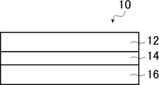
- FIG. 1 is a schematic cross-sectional view showing an example of the optical film of the present invention.
- the present invention will be described in detail.
- the description of the constituent elements described below may be based on a typical embodiment of the present invention, but the present invention is not limited to such an embodiment.
- the numerical range represented by using "-" means a range including the numerical values before and after "-" as the lower limit value and the upper limit value.
- a substance corresponding to each component may be used alone or in combination of two or more.
- the content of the component means the total content of the substances used in combination unless otherwise specified.
- the bonding direction of the divalent group (for example, -CO-NR-) described is not particularly limited unless the bonding position is specified, and for example, the formula (for example) described later will be used.
- D 1 in I) is -CO-NR-, if the position bonded to the G 1 side is * 1 and the position bonded to the Ar 1 side is * 2, D 1 is * 1. It may be -CO-NR- * 2 or * 1-NR-CO- * 2.
- the optically anisotropic layer of the present invention is an optical difference obtained by polymerizing a polymerizable liquid crystal composition containing a polymerizable liquid crystal compound (hereinafter, formally abbreviated as "the polymerizable liquid crystal composition of the present invention"). It is a square layer. Further, in the optically anisotropic layer of the present invention, when the amplitude value of each wavelength obtained by Fourier transforming the data of the three-dimensional surface roughness is L, the amplitude value L having a wavelength of 5.0 ⁇ m or more is 0. This is an optically anisotropic layer having an amplitude value L of 125 or more and a wavelength of 2.0 to 2.5 ⁇ m of 0.025 or less.
- the amplitude value L of each wavelength means a value calculated by the following procedure.
- -Measurement mode Phase mode-Complementation: Yes-Baseline correction: Yes-Objective lens magnification: 10 times
- FFT fast Fourier transformed
- the concentric amplitude distribution when the frequency F is set every 100 (1 / mm) is obtained.
- the wavelength is 5.0 ⁇ m
- F ⁇ 200 the amplitude value corresponds to the amplitude value L having a wavelength of 5.0 ⁇ m or more.
- the amplitude value of 400 ⁇ F ⁇ 500 corresponds to the amplitude value L having a wavelength of 2.0 to 2.5 ⁇ m.
- the amplitude value L of the wavelength 5.0 ⁇ m or more is 0.125 or more and the wavelength.
- an optically anisotropic layer having an amplitude value L of 2.0 to 2.5 ⁇ m of 0.025 or less the occurrence of haze is suppressed and the winding suitability is improved. This is not clear in detail, but the present inventors speculate as follows. First, it is considered that the surface of the optically anisotropic layer has a periodic uneven shape due to volume shrinkage when the polymerizable liquid crystal composition is polymerized.
- the amplitude value L having a wavelength of 5.0 ⁇ m or more is preferably 0.235 or more, and more preferably 0.235 or more and 0.600 or less, for the reason that the winding suitability is improved. ..
- the amplitude value L of the wavelength 2.0 to 2.5 ⁇ m is preferably 0.021 or less, preferably 0.001 or more and 0.021 or less, for the reason that the occurrence of haze is further suppressed. More preferably.
- the polymerizable liquid crystal composition of the present invention is immobilized in a smectic phase liquid crystal state because the contrast of the image display device having the optically anisotropic layer is good. Is preferable.
- the polymerizable liquid crystal compound contained in the polymerizable liquid crystal composition of the present invention is not particularly limited as long as it is a liquid crystal compound having a polymerizable group, and is preferably a liquid crystal compound having two or more polymerizable groups.
- the polymerizable group contained in the polymerizable crystal compound is not particularly limited, but a polymerizable group capable of radical polymerization or cationic polymerization is preferable.
- a known radically polymerizable group can be used, and suitable examples thereof include an acryloyloxy group and a methacryloyloxy group.
- the acryloyloxy group is generally faster in terms of polymerization rate, and the acryloyloxy group is preferable from the viewpoint of improving productivity, but the methacryloyloxy group can also be used as the polymerizable group in the same manner.
- a known cationically polymerizable group can be used, and specifically, an alicyclic ether group, a cyclic acetal group, a cyclic lactone group, a cyclic thioether group, a spiroorthoester group, and vinyloxy.
- the group can be mentioned.
- an alicyclic ether group or a vinyloxy group is preferable, and an epoxy group, an oxetanyl group, or a vinyloxy group is particularly preferable.
- particularly preferable polymerizable groups include polymerizable groups represented by any of the following formulas (P-1) to (P-20).
- liquid crystal compounds can be classified into rod-shaped type and disk-shaped type according to their shapes. Furthermore, there are low molecular weight and high molecular weight types, respectively.
- a polymer generally refers to a polymer having a degree of polymerization of 100 or more (Polymer Physics / Phase Transition Dynamics, Masao Doi, p. 2, Iwanami Shoten, 1992).
- any liquid crystal compound can be used, but it is preferable to use a rod-shaped liquid crystal compound or a discotic liquid crystal compound (disk-shaped liquid crystal compound). Two or more kinds of rod-shaped liquid crystal compounds, two or more kinds of disk-shaped liquid crystal compounds, or a mixture of a rod-shaped liquid crystal compound and a disk-shaped liquid crystal compound may be used.
- rod-shaped liquid crystal compound for example, those described in claim 1 of JP-A-11-513019 and paragraphs [0026] to [0098] of JP-A-2005-289980 can be preferably used, and discotics can be used.
- liquid crystal compound for example, those described in paragraphs [0020] to [0067] of JP2007-108732 and paragraphs [0013] to [0108] of JP2010-244038 can be preferably used. However, it is not limited to these.
- the polymerizable liquid crystal compound is preferably a polymerizable liquid crystal compound having reverse wavelength dispersibility (hereinafter, also abbreviated as “reverse dispersion liquid crystal compound”) for the reason of improving the optical compensatory property.
- reverse dispersion liquid crystal compound a polymerizable liquid crystal compound having reverse wavelength dispersibility
- the term "polymerizable liquid crystal compound having inverse wavelength dispersibility” as used herein refers to an in-plane retardation (Re) value at a specific wavelength (visible light range) of a retardation film produced using the same. When the measurement is performed, the Re value becomes equal or higher as the measurement wavelength becomes larger.
- Examples of the inversely dispersed liquid crystal compound include a compound represented by the following formula (I).
- a1, a2, g1 and g2 independently represent 0 or 1, respectively. However, at least one of a1 and g1 represents 1, and at least one of a2 and g2 represents 1. Further, in the above formula (I), q1 represents 1 or 2. Further, in the above formula (I), D 1 , D 2 , D 3 , D 4 , D 5 and D 6 are independently single-bonded or -CO-, -O-, -S-,-, respectively.
- R 1 ⁇ R 5 independently represents a hydrogen atom, a fluorine atom, or an alkyl group having 1 to 12 carbon atoms.
- a plurality of D 2 may each be the same or different.
- G 1 and G 2 each independently have an aromatic ring having 6 to 20 carbon atoms which may have a substituent or a carbon which may have a substituent.
- a 1 and A 2 are independently aromatic rings having 6 to 20 carbon atoms which may have a substituent, or carbons which may have a substituent.
- SP 1 and SP 2 are independently a single bond, a linear or branched alkylene group having 1 to 12 carbon atoms, or a linear chain having 1 to 12 carbon atoms.
- Q represents a substituent.
- L 1 and L 2 each independently represent a monovalent organic group, and at least one of L 1 and L 2 represents a polymerizable group.
- Ar is at least one polymerizable group of the formula If (Ar-3) an aromatic ring represented by the, L 1 and L 2 and L 3 and L 4 in formula (Ar-3) Represents.
- a1, a2, g1 and g2 are preferably 1 for the reason that the polymerizable liquid crystal composition of the present invention tends to show the liquid crystal state of the smectic phase. Further, it is preferable that both a1 and a2 are 0 and both g1 and g2 are 1 for the reason that the contrast of the image display device having the optically anisotropic layer is good.
- q1 is preferably 1.
- examples of the divalent linking group represented by one aspect of D 1 , D 2 , D 3 , D 4 , D 5 and D 6 include -CO-, -O-, and -CO-.
- R 1 , R 2 and R 5 independently represent a hydrogen atom, a fluorine atom, or an alkyl group having 1 to 12 carbon atoms. Of these, any of -CO-, -O-, and -CO-O- is preferable.
- examples of the aromatic ring having 6 to 20 carbon atoms represented by one aspect of G 1 and G 2 include an aromatic hydrocarbon ring such as a benzene ring, a naphthalene ring, an anthracene ring, and a phenanthroline ring.
- Aromatic heterocycles such as furan ring, pyrrole ring, thiophene ring, pyridine ring, thiazole ring, and benzothiazole ring; Of these, a benzene ring (for example, a 1,4-phenyl group) is preferable.
- the divalent alicyclic hydrocarbon group having 5 to 20 carbon atoms represented by one aspect of G 1 and G 2 is preferably a 5-membered ring or a 6-membered ring.
- the alicyclic hydrocarbon group may be saturated or unsaturated, but a saturated alicyclic hydrocarbon group is preferable.
- the divalent alicyclic hydrocarbon group represented by G 1 and G 2 for example, the description in paragraph [0078] of JP2012-21068A can be referred to, and this content is incorporated in the present specification. ..
- G 1 and G 2 in the above formula (I) are preferably cycloalkane rings for the reason that the contrast of the image display device having the optically anisotropic layer is good.
- the cycloalkane ring include a cyclohexane ring, a cyclopeptane ring, a cyclooctane ring, a cyclododecane ring, and a cyclododecane ring.
- a cyclohexane ring is preferred, a 1,4-cyclohexylene group is more preferred, and a trans-1,4-cyclohexylene group is even more preferred.
- G 1 and G 2 are designated as substituents which may be contained in an aromatic ring having 6 to 20 carbon atoms or a divalent alicyclic hydrocarbon group having 5 to 20 carbon atoms.
- Examples thereof include a group and an N-alkylcarbamate group, and among them, an alkyl group, an alkoxy group, an alkoxycarbonyl group, an alkylcarbonyloxy group, or a halogen atom is preferable.
- the alkyl group is preferably a linear, branched or cyclic alkyl group having 1 to 18 carbon atoms, and an alkyl group having 1 to 8 carbon atoms (for example, methyl group, ethyl group, propyl group, isopropyl group, n).
- alkoxy group an alkoxy group having 1 to 18 carbon atoms is preferable, an alkoxy group having 1 to 8 carbon atoms (for example, a methoxy group, an ethoxy group, an n-butoxy group, a methoxyethoxy group, etc.) is more preferable, and an alkoxy group having 1 carbon number is preferable.
- Alkoxy groups of ⁇ 4 are more preferable, and methoxy groups or ethoxy groups are particularly preferable.
- the alkoxycarbonyl group include a group in which an oxycarbonyl group (—O—CO— group) is bonded to the alkyl group exemplified above, and among them, a methoxycarbonyl group, an ethoxycarbonyl group, an n-propoxycarbonyl group or an isopropoxy.
- a carbonyl group is preferred, and a methoxycarbonyl group is more preferred.
- alkylcarbonyloxy group examples include a group in which a carbonyloxy group (-CO-O- group) is bonded to the alkyl group exemplified above, and among them, a methylcarbonyloxy group, an ethylcarbonyloxy group, and an n-propylcarbonyloxy group.
- a group or an isopropylcarbonyloxy group is preferable, and a methylcarbonyloxy group is more preferable.
- the halogen atom examples include a fluorine atom, a chlorine atom, a bromine atom and an iodine atom, and among them, a fluorine atom or a chlorine atom is preferable.
- the aromatic rings having 6 to 20 or more carbon atoms shown in one aspect of A 1 and A 2 are the same as those described in G 1 and G 2 in the above formula (I). Can be mentioned. Further, in the above formula (I), as the divalent alicyclic hydrocarbon group having 5 to 20 carbon atoms represented by one aspect of A 1 and A 2 , in G 1 and G 2 in the above formula (I). Examples are similar to those described. Regarding A 1 and A 2 , the substituent which the aromatic ring having 6 to 20 carbon atoms or the divalent alicyclic hydrocarbon group having 5 to 20 carbon atoms may have is the above formula (I). Examples include the same substituents that G 1 and G 2 may have.
- examples of the linear or branched alkylene group having 1 to 12 carbon atoms represented by one aspect of SP 1 and SP 2 include a methylene group, an ethylene group, a propylene group, a butylene group and a pentylene.
- a group, a hexylene group, a methylhexylene group, a heptylene group and the like are preferably mentioned.
- SP 1 and SP 2 have one or more of -CH 2- constituting a linear or branched alkylene group having 1 to 12 carbon atoms of -O-, -S-, and -NH.
- Examples of the monovalent organic group represented by L 1 and L 2 in the above formula (I) include an alkyl group, an aryl group, and a heteroaryl group.
- the alkyl group may be linear, branched or cyclic, but linear is preferred.
- the number of carbon atoms of the alkyl group is preferably 1 to 30, more preferably 1 to 20, and even more preferably 1 to 10.
- the aryl group may be monocyclic or polycyclic, but monocyclic is preferable.
- the aryl group preferably has 6 to 25 carbon atoms, more preferably 6 to 10 carbon atoms.
- the heteroaryl group may be monocyclic or polycyclic.
- the number of heteroatoms constituting the heteroaryl group is preferably 1 to 3.
- the hetero atom constituting the heteroaryl group is preferably a nitrogen atom, a sulfur atom, or an oxygen atom.
- the heteroaryl group preferably has 6 to 18 carbon atoms, more preferably 6 to 12 carbon atoms.
- the alkyl group, the aryl group and the heteroaryl group may be unsubstituted or have a substituent. Examples of the substituent include the same substituents that G 1 and G 2 in the above formula (I) may have.
- examples of the polymerizable group represented by at least one of L 1 and L 2 include those similar to the above-mentioned radical polymerization or cationically polymerizable polymerizable group, and among them, the above-mentioned formula (P).
- a polymerizable group represented by any one of -1) to (P-20) is preferably used.
- both L 1 and L 2 in the above formula (I) are polymerizable groups for the reason that the durability of the optically anisotropic layer is good, and an acryloyloxy group. Alternatively, it is more preferably a methacryloyloxy group.
- Ar represents any aromatic ring selected from the group consisting of the groups represented by the following formulas (Ar-1) to (Ar-7).
- q1 is 2, the plurality of Ars may be the same or different.
- * represents the bonding position with D 1 or D 2 in the above formula (I).
- Q 1 represents N or CH
- Q 2 represents -S-, -O-, or -N (R 6 )-
- R 6 is a hydrogen atom or Represents an alkyl group having 1 to 6 carbon atoms
- Y 1 is an aromatic hydrocarbon group having 6 to 12 carbon atoms which may have a substituent
- an aromatic group having 3 to 12 carbon atoms which may have a substituent A group heterocyclic group or an alicyclic hydrocarbon group having 6 to 20 carbon atoms which may have a substituent is represented, and one or more of -CH 2- constituting the alicyclic hydrocarbon group is -O. It may be substituted with ⁇ , —S— or ⁇ NH—.
- alkyl group having 1 to 6 carbon atoms indicated by R 6 include methyl group, ethyl group, propyl group, isopropyl group, n-butyl group, isobutyl group, sec-butyl group and tert-butyl.
- Examples include a group, an n-pentyl group, and an n-hexyl group.
- aromatic hydrocarbon group having 6 to 12 carbon atoms indicated by Y 1 include an aryl group such as a phenyl group, a 2,6-diethylphenyl group and a naphthyl group.
- Examples of the aromatic heterocyclic group having 3 to 12 carbon atoms indicated by Y 1 include heteroaryl groups such as a thienyl group, a thiazolyl group, a frill group and a pyridyl group.
- Examples of the alicyclic hydrocarbon group having 6 to 20 carbon atoms indicated by Y 1 include a cyclohexylene group, a cyclopentylene group, a norbornene group, and an adamantylene group.
- examples of the substituent that Y 1 may have include the same substituents that G 1 and G 2 in the above formula (I) may have.
- Z 1 , Z 2 and Z 3 are independently hydrogen atoms, monovalent aliphatic hydrocarbon groups having 1 to 20 carbon atoms, and carbons, respectively.
- Nitro group, -OR 7 , -NR 8 R 9 , -SR 10 , -COOR 11 , or -COR 12 where R 7 to R 12 are independent of hydrogen atoms or carbon atoms 1 to 6, respectively.
- Z 1 and Z 2 may be bonded to each other to form an aromatic ring.
- the monovalent aliphatic hydrocarbon group having 1 to 20 carbon atoms an alkyl group having 1 to 15 carbon atoms is preferable, an alkyl group having 1 to 8 carbon atoms is more preferable, and specifically, a methyl group and an ethyl group.
- Isopropyl group, tert-pentyl group (1,1-dimethylpropyl group), tert-butyl group, 1,1-dimethyl-3,3-dimethyl-butyl group are more preferable, and methyl group, ethyl group, tert-butyl group. Groups are particularly preferred.
- Examples of the monovalent alicyclic hydrocarbon group having 3 to 20 carbon atoms include a cyclopropyl group, a cyclobutyl group, a cyclopentyl group, a cyclohexyl group, a cycloheptyl group, a cyclooctyl group, a cyclodecyl group, a methylcyclohexyl group and an ethylcyclohexyl.
- Monocyclic saturated hydrocarbon groups such as groups; cyclobutenyl group, cyclopentenyl group, cyclohexenyl group, cycloheptenyl group, cyclooctenyl group, cyclodecenyl group, cyclopentadienyl group, cyclohexadienyl group, cyclooctadienyl group, cyclodeca Monocyclic unsaturated hydrocarbon groups such as diene; bicyclo [2.2.1] heptyl group, bicyclo [2.2.2] octyl group, tricyclo [5.2.1.0 2,6 ] decyl group, Tricyclo [3.3.1.1 3,7 ] decyl group, tetracyclo [6.2.1.1 3,6 .
- Polycyclic saturated hydrocarbon groups such as dodecyl group and adamantyl group; and the like.
- Specific examples of the monovalent aromatic hydrocarbon group having 6 to 20 carbon atoms include a phenyl group, a 2,6-diethylphenyl group, a naphthyl group, a biphenyl group and the like, and have 6 to 12 carbon atoms.
- Aryl groups particularly phenyl groups
- Specific examples of the monovalent aromatic heterocyclic group having 6 to 20 carbon atoms include a 4-pyridyl group, a 2-furyl group, a 2-thienyl group, a 2-pyrimidinyl group, and a 2-benzothiazolyl group. Can be mentioned.
- halogen atom examples include a fluorine atom, a chlorine atom, a bromine atom, an iodine atom and the like, and among them, a fluorine atom, a chlorine atom and a bromine atom are preferable.
- alkyl group having 1 to 6 carbon atoms represented by R 7 to R 10 include, for example, a methyl group, an ethyl group, a propyl group, an isopropyl group, an n-butyl group, an isobutyl group, and sec-butyl. Examples include groups, tert-butyl groups, n-pentyl groups, n-hexyl groups and the like.
- Z 1 and Z 2 may be bonded to each other to form an aromatic ring.
- Z 1 and Z 2 in the above formula (Ar-1) may be bonded to each other to form an aromatic ring.
- Examples of the structure of the case include a group represented by the following formula (Ar-1a).
- * represents the bonding position with D 1 or D 2 in the above formula (I).
- Q 1 , Q 2 and Y 1 are the same as those described in the above formula (Ar-1).
- a 3 and A 4 are each independently, -O -, - N (R 13) -, - S-, and from -CO- Represents a group selected from the group, where R 13 represents a hydrogen atom or a substituent.
- R 13 represents a hydrogen atom or a substituent.
- Examples of the substituent represented by R 13 include the same substituents that G 1 and G 2 in the above formula (I) may have.
- X represents a non-metal atom of Groups 14 to 16 to which a hydrogen atom or a substituent may be bonded.
- RC1 represents a hydrogen atom or a substituent. ] Can be mentioned.
- substituents include an alkyl group, an alkoxy group, an alkyl substituted alkoxy group, a cyclic alkyl group, an aryl group (for example, a phenyl group, a naphthyl group, etc.), a cyano group, an amino group, a nitro group, and an alkyl group.
- substituents include a carbonyl group, a sulfo group and a hydroxyl group.
- R 2 -, - CR 3 CR 4 -, - NR 5 -, or a divalent linking group formed from these two or more thereof,
- R 1 ⁇ R 5 are each independently a hydrogen atom, It represents a fluorine atom or an alkyl group having 1 to 12 carbon atoms.
- examples of the divalent linking group include the same groups as those described in D 1 , D 2 , D 3 , D 4 , D 5 and D 6 in the above formula (I).
- SP 3 and SP 4 are independently a single bond, a linear or branched alkylene group having 1 to 12 carbon atoms, or a direct group having 1 to 12 carbon atoms.
- Examples of the substituent include the same substituents that G 1 and G 2 in the above formula (I) may have.
- examples of the alkylene group include the same groups as those described in SP 1 and SP 2 in the above formula (I).
- L 3 and L 4 independently represent monovalent organic groups, respectively, and at least 1 of L 3 and L 4 and L 1 and L 2 in the above formula (I).
- the monovalent organic group include those similar to those described in L 1 and L 2 in the above formula (I).
- the polymerizable group the same group as the above-mentioned radical polymerization or cationically polymerizable polymerizable group can be mentioned, and among them, it is represented by any of the above-mentioned formulas (P-1) to (P-20). Polymerizable groups are preferred.
- Ax has at least one aromatic ring selected from the group consisting of an aromatic hydrocarbon ring and an aromatic heterocycle, and has 2 to 30 carbon atoms. Represents an organic group.
- Ay is a hydrogen atom, an alkyl group having 1 to 12 carbon atoms which may have a substituent, or an aromatic hydrocarbon ring and aromatic. Represents an organic group having 2 to 30 carbon atoms and having at least one aromatic ring selected from the group consisting of group heterocycles.
- the aromatic ring in Ax and Ay may have a substituent, or Ax and Ay may be bonded to form a ring.
- Q 3 represents a hydrogen atom or an alkyl group having 1 to 6 carbon atoms which may have a substituent.
- Examples of Ax and Ay include those described in paragraphs [0039] to [0995] of International Publication No. 2014/010325.
- the alkyl group of Q 3 is 1 to 20 carbon atoms shown, specifically, for example, a methyl group, an ethyl group, a propyl group, an isopropyl group, n- butyl group, isobutyl group, sec- butyl group, tert -Butyl group, n-pentyl group, n-hexyl group and the like can be mentioned, and examples of the substituent are the same as the substituents that G 1 and G 2 in the above formula (I) may have. Can be mentioned.
- Examples of the compound represented by the above formula (I) include compounds represented by the general formula (1) described in JP-A-2010-084032 (particularly, those described in paragraph numbers [0067] to [0073].
- K side chain structure
- “*" shown in the side chain structure of K represents the bonding position with the aromatic ring.
- the groups adjacent to the acryloyloxy group and the methacryloyl group are propylene groups (methyl groups are ethylene groups, respectively). It represents a substituted group) and represents a mixture of positional isomers with different methyl group positions.
- the polymerizable liquid crystal compound is preferably a compound that exhibits a liquid crystal state of the smectic phase because the contrast of the image display device having the optically anisotropic layer is good.
- the polymerizable liquid crystal composition of the present invention has one polymerizable group because the generation of haze in the optically anisotropic layer is further suppressed and the contrast of the image display device having the optically anisotropic layer is improved. Moreover, it preferably contains a monofunctional compound having two or more ring structures of at least one selected from the group consisting of aromatic rings or alicyclic rings.
- examples of the polymerizable group contained in the monofunctional compound include those similar to the radical polymerization or cationically polymerizable polymerizable group described in the above-mentioned polymerizable liquid crystal compound, and among them, the above-mentioned formula (P-1). )-(P-20), the polymerizable group represented by any of (P-20) is preferably mentioned.
- examples of the aromatic ring include an aromatic ring having 6 to 20 carbon atoms which may have a substituent, and specifically, benzene.
- Aromatic hydrocarbon rings such as ring, naphthalene ring, anthracene ring, and phenanthroline ring; furan ring, thiophene ring, pyrrole ring, oxazole ring, isooxazole ring, oxaziazole ring, thiazole ring, isothiazole ring
- Aromatic heterocycles such as thiasiazole ring, imidazole ring, pyrazole ring, triazole ring, flazan ring, tetrazole ring, pyridine ring, pyridazine ring, pyrimidine ring, pyrazine ring, triazine ring, tetrazine ring, and benzothiazole ring;
- Aromatic heterocycles such as thiasiazol
- Examples of the alicyclic ring include a cycloalkane ring which may have a substituent, and specific examples thereof include a cyclohexane ring, a cyclopeptane ring, a cyclooctane ring, a cyclododecane ring, and a cyclododecane ring. Of these, a cyclohexane ring is preferable.
- Examples of the substituent include the same substituents that G 1 and G 2 in the above formula (I) described in the above-mentioned polymerizable liquid crystal compound may have.
- the monofunctional compound is substituted with a polymerizable group because the occurrence of haze in the optically anisotropic layer is further suppressed and the contrast of the image display device having the optically anisotropic layer is improved.
- It has an aromatic ring which may have a group, a polymerizable group constitutes one end of the molecule, and an aromatic ring or a substituent which may have an aromatic ring is the other end of the molecule. It is preferable that it is a compound constituting the above.
- one end and the other end refer to the starting atom and the ending atom for which the maximum number of atoms is calculated when the atoms on the bond of the compound are connected at the shortest distance, respectively, and they are hydrogen atoms.
- a polymerizable group when a polymerizable group constitutes a terminal, it means that the polymerizable group contains a terminal atom, and when an aromatic ring constitutes a terminal, it means that the aromatic ring contains a terminal atom, and a substituent is a terminal. Consists of means that the substituent contains a terminal atom.
- the monofunctional compound is preferably a compound represented by the following formula (II) for the reason that the planar condition of the optically anisotropic layer is improved.
- a3 and g3 each independently represent an integer of 0 to 2. However, a3 and g3 represent integers of 1 to 3 in total.
- R 2 -, - CR 3 CR 4 -, - NR 5 -, or a divalent linking group formed from these two or more thereof
- R 1 ⁇ R 5 are each independently a hydrogen atom , Fluorine atom, or an alkyl group having 1 to 12 carbon atoms.
- G 3 is an aromatic ring of 6 to 20 carbon atoms which may have a substituent, or carbon atoms which may have a substituent group 5 to 20 bivalent
- g3 is 2, a plurality of G 3 are, may each be the same or different.
- a 5 is an aromatic ring of 6 to 20 carbon atoms which may have a substituent, or carbon atoms which may have a substituent group 5 to 20 bivalent
- the plurality of A 5, may each be the same or different.
- SP 5 has a single bond, a linear or branched alkylene group having 1 to 12 carbon atoms, or a linear or branched alkylene group having 1 to 12 carbon atoms.
- One or more of the constituent -CH 2- represents a divalent linking group substituted with -O-, -S-, -NH-, -N (Q)-, or -CO-, where Q represents a divalent linking group.
- Q represents a divalent linking group.
- L 5 represents a polymerizable group.
- M represents an aromatic ring which may have a substituent.
- a3 and g3 are preferably 1 because the polymerizable liquid crystal composition of the present invention tends to show the liquid crystal state of the smectic phase.
- the divalent linking group represented by one aspect of D 9 , D 10 and D 11 in the above formula (II) for example, the divalent linking group represented by one aspect such as D 1 in the above formula (I).
- D 9 , D 10 and D 11 in the above formula (I) for example, the divalent linking group represented by one aspect such as D 1 in the above formula (I).
- D 1 in the above formula (I) The same as those exemplified as above are mentioned, and among them, any of -CO-, -O-, and -CO-O- is preferable.
- the aromatic ring of one embodiment 6 to 20 carbon atoms shown in G 3 for example, of the formula (I) having 6 to carbon atoms indicated by an embodiment such as G 1 in 20 aromatic ring Among them, a benzene ring (for example, a 1,4-phenyl group) is preferable.
- Examples of the divalent alicyclic hydrocarbon group of No. 5 to 20 include those similar to those exemplified, among which the cycloalkane ring is preferable, the cyclohexane ring is more preferable, and the 1,4-cyclohexylene group is further preferable. , Trans-1,4-cyclohexylene groups are particularly preferred.
- the G 3 examples of the divalent alicyclic hydrocarbon group substituents which may be possessed by the aromatic ring or having 5 to 20 carbon atoms of 6 to 20 carbon atoms is, above Examples thereof include the same substituents that G 1 and G 2 in the above formula (I) described in the above-mentioned polymerizable liquid crystal compound may have.
- the aromatic ring having 6 to 20 or more carbon atoms indicated by an aspect of A 5 include the same as those described in G 1 and G 2 in the formula (I).
- the divalent alicyclic hydrocarbon group of one embodiment is 5 to 20 carbon atoms shown in the A 5, those described in G 1 and G 2 in the formula (I) The same can be mentioned.
- the polymerizable liquid crystal compounds described above in the aromatic ring or having 5 to 20 carbon atoms of 6 to 20 carbon atoms described Examples thereof include the same substituents that G 1 and G 2 in the above formula (I) may have.
- examples of the polymerizable group represented by L 5 include those similar to the radical polymerization or cationically polymerizable polymerizable group described in the above-mentioned polymerizable liquid crystal compound, and among them, the above formula.
- Preferred examples include the polymerizable group represented by any one of (P-1) to (P-20).
- the aromatic ring represented by M for example, include aromatic ring having 6 to 20 carbon atoms, specifically, the carbon indicated by an embodiment such as G 1 in the formula (I)
- Examples of the aromatic ring of No. 6 to 20 include those similar to those exemplified, and among them, a benzene ring (for example, a 1,4-phenyl group) is preferable.
- the substituents that the aromatic ring may have are the substituents that G 1 and G 2 in the above formula (I) described in the above-mentioned polymerizable liquid crystal compound may have. Similar things can be mentioned.
- Specific examples of the compound represented by the above formula (II) include compounds represented by the following formulas (TN-1) to (TN-21).
- the content of the monofunctional compound when the monofunctional compound is contained is described above. It is preferably 4 to 20 parts by mass, and more preferably 8 to 16 parts by mass with respect to 100 parts by mass of the polymerized liquid crystal compound.
- the atomic number D1 of the above-mentioned polymerizable liquid crystal compound and the above-mentioned monofunctional compound are used. It is preferable that the number of atoms D2 satisfies the relationship of the following formula (1), and more preferably the relationship of the following formula (2) is satisfied. 0.35 ⁇ D2 / D1 ⁇ 0.45 ... (1) 0.35 ⁇ D2 / D1 ⁇ 0.45 ...
- the number of atoms represents the number of atoms on the bond connecting one end of the compound and the other end at the shortest distance, and does not include a hydrogen atom. Further, one end and the other end refer to the starting atom and the ending atom for which the maximum number of atoms is calculated when the atoms on the bond of the compound are connected at the shortest distance, respectively, and the hydrogen atom is It shall not be included.
- the polymerizable liquid crystal composition of the present invention preferably contains a polymerization initiator.
- the polymerization initiator used is preferably a photopolymerization initiator capable of initiating a polymerization reaction by irradiation with ultraviolet rays.
- Examples of the photopolymerization initiator include ⁇ -carbonyl compounds (described in US Pat. No. 2,376,661 and US Pat. No. 2,376,670), acidoin ethers (described in US Pat. No. 2,448,828), and ⁇ -hydrogen-substituted fragrances.
- Group acidoine compounds described in US Pat. No. 2722512
- polynuclear quinone compounds described in US Pat. Nos.
- the polymerization initiator is preferably an oxime type polymerization initiator, and specific examples thereof are described in paragraphs [0049] to [0052] of International Publication No. 2017/170443. Agents are mentioned.
- the polymerizable liquid crystal composition of the present invention preferably contains a solvent from the viewpoint of workability for forming the optically anisotropic layer of the present invention.
- a solvent from the viewpoint of workability for forming the optically anisotropic layer of the present invention.
- the solvent include ketones (for example, acetone, 2-butanone, methylisobutylketone, cyclohexanone, cyclopentanone, etc.), ethers (for example, dioxane, tetrahydrofuran, etc.), and aliphatic hydrocarbons.
- the polymerizable liquid crystal composition of the present invention preferably contains a leveling agent from the viewpoint of keeping the surface of the optically anisotropic layer of the present invention smooth and facilitating orientation control.
- a leveling agent is preferably a fluorine-based leveling agent or a silicon-based leveling agent because it has a high leveling effect on the amount of addition, and a fluorine-based leveling agent from the viewpoint of less likely to cause crying (bloom, bleed). Is more preferable.
- Specific examples of the leveling agent include the compounds described in paragraphs [0079] to [0102] of JP-A-2007-069471, and the general formulas described in JP-A-2013-047204.
- the polymerizable liquid crystal composition of the present invention may contain an orientation control agent, if necessary.
- the orientation control agent can form various orientation states such as homeotropic orientation (vertical orientation), tilt orientation, hybrid orientation, and cholesteric orientation in addition to homogenius orientation, and can make a specific orientation state more uniform and more uniform. It can be realized by precise control.
- a low-molecular-weight orientation control agent or a high-molecular-weight orientation control agent can be used as the orientation control agent that promotes homogenous orientation.
- the low-molecular-weight orientation control agent include paragraphs [0009] to [0083] of JP-A-2002-20363, paragraphs [0111]-[0120] of JP-A-2006-106662, and JP-A-2012.
- paragraphs [0021] to [0029] of Japanese Patent Application Laid-Open No. 211306 can be referred to, and this content is incorporated in the present specification.
- orientation control agent for forming or promoting homeotropic orientation examples include boronic acid compounds and onium salt compounds. Specifically, paragraphs [0023] to [0032] of JP-A-2008-225281. , Paragraphs [0052] to [0058] of JP2012-208397A, paragraphs [0024] to [0055] of JP2008-026730, and [0043] to [0055] of JP2016-193869. The compounds described in paragraphs and the like can be taken into account, the contents of which are incorporated herein by reference.
- the cholesteric orientation can be realized by adding a chiral agent to the polymerizable liquid crystal composition of the present invention, and the turning direction of the cholesteric orientation can be controlled by the direction of the chiral property.
- the pitch of the cholesteric orientation can be controlled according to the orientation regulating force of the chiral agent.
- the content is preferably 0.01 to 10% by mass, more preferably 0.05 to 5% by mass, based on the total solid content mass in the composition.
- the content is in this range, a uniform and highly transparent cured product can be obtained without precipitation, phase separation, orientation defects, etc., while achieving the desired orientation state.
- the polymerizable liquid crystal composition of the present invention may contain components other than those described above, and examples thereof include surfactants, tilt angle control agents, orientation aids, plasticizers, and cross-linking agents.
- the optically anisotropic layer of the present invention is a cured product obtained by polymerizing the above-mentioned polymerizable liquid crystal composition of the present invention.
- the cured product can be formed on an arbitrary support in the optical film of the present invention described later or on a polarizer in the polarizing plate of the present invention described later.
- Examples of the method for forming the cured product include a method of using the above-mentioned polymerizable liquid crystal composition of the present invention to achieve a desired orientation state and then immobilizing the cured product by polymerization.
- the polymerization conditions are not particularly limited, but it is preferable to use ultraviolet rays in the polymerization by light irradiation.
- the irradiation amount is preferably 10 mJ / cm 2 to 50 J / cm 2 , more preferably 20 mJ / cm 2 to 5 J / cm 2 , and even more preferably 30 mJ / cm 2 to 3 J / cm 2. , 50 to 1000 mJ / cm 2 is particularly preferable. Further, in order to promote the polymerization reaction, it may be carried out under heating conditions.
- the above-mentioned polymerizable liquid crystal composition of the present invention is a composition showing a liquid crystal state of a smectic phase, the phase transition temperature (N—Sm transition temperature) from the nematic phase to the smectic phase and the time of UV irradiation It is preferable to carry out the polymerization at a temperature at which the difference from the temperature (curing temperature) of the above is less than 20 ° C.
- the optically anisotropic layer of the present invention is preferably an optically anisotropic layer satisfying the following formula (III). 0.50 ⁇ Re (450) / Re (550) ⁇ 1.00 ... (III)
- Re (450) represents the in-plane lettering of the optically anisotropic layer at a wavelength of 450 nm
- Re (550) represents the in-plane letter of the optically anisotropic layer at a wavelength of 550 nm.
- an optically anisotropic layer is preferably a positive A plate or a positive C plate, and more preferably a positive A plate.
- the positive A plate (positive A plate) and the positive C plate (positive C plate) are defined as follows.
- the refractive index in the slow axis direction in the film plane (the direction in which the refractive index in the plane is maximized) is nx
- the refractive index in the direction orthogonal to the slow phase axis in the plane in the plane is ny
- the refraction in the thickness direction is nz
- the positive A plate satisfies the relation of the formula (A1)
- the positive C plate satisfies the relation of the formula (C1).
- the positive A plate shows a positive value for Rth
- the positive C plate shows a negative value for Rth.
- ⁇ includes not only the case where both are completely the same, but also the case where both are substantially the same. “Substantially the same” means that, for example, in the positive A plate, (ny-nz) ⁇ d (where d is the thickness of the film) is -10 to 10 nm, preferably -5 to 5 nm. It is included in “ny ⁇ nz”, and when (nx-nz) xd is -10 to 10 nm, preferably -5 to 5 nm, it is also included in "nx ⁇ nz”.
- (nx ⁇ ny) ⁇ d (where d is the thickness of the film) is 0 to 10 nm, preferably 0 to 5 nm, it is also included in “nx ⁇ ny”.
- Re (550) is preferably 100 to 180 nm, more preferably 120 to 160 nm, and 130 to 150 nm from the viewpoint of functioning as a ⁇ / 4 plate. It is more preferably 130 to 140 nm, and particularly preferably 130 to 140 nm.
- the " ⁇ / 4 plate” is a plate having a ⁇ / 4 function, and specifically, a function of converting linearly polarized light having a specific wavelength into circularly polarized light (or converting circularly polarized light into linearly polarized light). It is a plate having.
- the optical film of the present invention is an optical film having the optically anisotropic layer of the present invention.
- FIG. 1 is a schematic cross-sectional view showing an example of the optical film of the present invention. Note that FIG. 1 is a schematic view, and the thickness relationship and positional relationship of each layer do not always match the actual ones, and the support and the alignment film shown in FIG. 1 are all arbitrary constituent members.
- the optical film 10 shown in FIG. 1 has a support 16, an alignment film 14, and an optically anisotropic layer 12 as a cured product in this order. Further, the optically anisotropic layer 12 may be a laminate of two or more different optically anisotropic layers.
- the polarizing plate of the present invention described later is used as a circular polarizing plate, or when the optical film of the present invention is used as an optical compensation film for an IPS type or FFS type liquid crystal display device, a positive A plate and a positive C are used. It is preferably a laminate of plates. Further, the optically anisotropic layer may be peeled off from the support and the optically anisotropic layer alone may be used as an optical film.
- various members used in the optical film of the present invention will be described in detail.
- optically anisotropic layer of the optical film of the present invention is the above-mentioned optically anisotropic layer of the present invention.
- the thickness of the optically anisotropic layer is not particularly limited, but is preferably 0.1 to 10 ⁇ m, more preferably 0.5 to 5 ⁇ m.
- the optical film of the present invention may have a support as a base material for forming an optically anisotropic layer.
- a support is preferably transparent, and specifically, the light transmittance is preferably 80% or more.
- Examples of such a support include a glass substrate and a polymer film, and examples of the polymer film material include a cellulose-based polymer; an acrylic-based polymer having an acrylic acid ester polymer such as polymethylmethacrylate and a lactone ring-containing polymer.
- the thickness of the support is not particularly limited, but is preferably 5 to 60 ⁇ m, more preferably 5 to 40 ⁇ m.
- the optical film of the present invention has any of the above-mentioned supports, it is preferable that the optical film has an alignment film between the support and the optically anisotropic layer.
- the support described above may also serve as an alignment film.
- the alignment film generally contains a polymer as a main component.
- the polymer material for an alignment film has been described in a large number of documents, and a large number of commercially available products are available.
- the polymer material used in the present invention is preferably polyvinyl alcohol or polyimide, or a derivative thereof. Particularly modified or unmodified polyvinyl alcohol is preferable.
- the alignment film for example, the alignment film described in International Publication No. 01/88574, p. 43, p. 24 to p. 49, p. 8; ], And the like; a liquid crystal alignment film formed by the liquid crystal alignment agent described in Japanese Patent Application Laid-Open No. 2012-155308; and the like.
- a photoalignment film as the alignment film because it is possible to prevent surface deterioration by not contacting the surface of the alignment film when forming the alignment film.
- the photoalignment film is not particularly limited, but is a polymer material such as a polyamide compound or a polyimide compound described in paragraphs [0024] to [0043] of International Publication No. 2005/096041; A liquid crystal alignment film formed by a liquid crystal alignment agent having a photo-oriented group; a trade name LPP-JP265CP manufactured by Polyimide, Inc. can be used.
- the thickness of the alignment film is not particularly limited, but from the viewpoint of alleviating the surface irregularities that may exist on the support and forming an optically anisotropic layer having a uniform film thickness, 0. It is preferably 01 to 10 ⁇ m, more preferably 0.01 to 1 ⁇ m, and even more preferably 0.01 to 0.5 ⁇ m.
- the optical film of the present invention preferably contains an ultraviolet (UV) absorber in consideration of the influence of external light (particularly ultraviolet rays).
- the ultraviolet absorber may be contained in the optically anisotropic layer of the present invention, or may be contained in a member other than the optically anisotropic layer constituting the optical film of the present invention.
- a support is preferably mentioned.
- the ultraviolet absorber any conventionally known one capable of exhibiting ultraviolet absorption can be used.
- a benzotriazole-based or hydroxyphenyltriazine-based ultraviolet absorber may be used from the viewpoint of obtaining the ultraviolet absorbing ability (ultraviolet blocking ability) used in an image display device because of its high ultraviolet absorbing ability. preferable.
- two or more kinds of ultraviolet absorbers having different maximum absorption wavelengths can be used in combination.
- Specific examples of the ultraviolet absorber include compounds described in paragraphs [0258] to [0259] of JP2012-18395, paragraphs [0055] to [0105] of JP2007-72163. Examples thereof include the compounds described in.
- Tinuvin400, Tinuvin405, Tinuvin460, Tinuvin477, Tinuvin479, Tinuvin1577 (all manufactured by BASF) and the like can be used.
- the polarizing plate of the present invention has the above-mentioned optical film of the present invention and a polarizer. Further, the polarizing plate of the present invention can be used as a circular polarizing plate when the optically anisotropic layer of the present invention described above is a ⁇ / 4 plate (positive A plate). When the polarizing plate of the present invention is used as a circular polarizing plate, the optically anisotropic layer of the present invention described above is a ⁇ / 4 plate (positive A plate), and the slow axis of the ⁇ / 4 plate and the polarizer described later are used.
- the angle formed by the absorption shaft is preferably 30 to 60 °, more preferably 40 to 50 °, further preferably 42 to 48 °, and particularly preferably 45 °.
- the polarizing plate of the present invention can also be used as an optical compensation film for an IPS type or FFS type liquid crystal display device.
- the above-mentioned optically anisotropic layer of the present invention is used at least one of a laminate of a positive A plate and a positive C plate.
- the angle formed by the slow axis of the positive A plate layer and the absorption axis of the polarizer described later is orthogonal or parallel, and specifically, the slow axis of the positive A plate layer and the slow axis of the positive A plate layer. It is more preferable that the angle formed by the polarizing element with the absorption axis, which will be described later, is 0 to 5 ° or 85 to 95 °.
- the "slow-phase axis" of the ⁇ / 4 plate or the positive A plate layer means the direction in which the refractive index is maximized in the plane of the ⁇ / 4 plate or the positive A plate layer, and the "absorption axis" of the polarizer. "" Means the direction of the highest absorbance.
- the polarizer of the polarizing plate of the present invention is not particularly limited as long as it is a member having a function of converting light into specific linearly polarized light, and conventionally known absorption type polarizers and reflection type polarizers can be used. ..
- absorption type polarizer an iodine-based polarizer, a dye-based polarizer using a dichroic dye, a polyene-based polarizer, and the like are used. Iodine-based polarized light and dye-based polarized light include coated and stretched polarized light, and both can be applied.
- the reflective polarizer a polarizer in which thin films having different birefringences are laminated, a wire grid type polarizer, a polarizer in which a cholesteric liquid crystal having a selective reflection region and a 1/4 wave plate are combined, and the like are used.
- polyvinyl alcohol-based resin polymer containing as a repeating unit -CH 2 -CHOH-, in particular, polyvinyl alcohol and ethylene - at least selected from the group consisting of vinyl alcohol copolymer It is preferable that the polymer contains one).
- the thickness of the polarizer is not particularly limited, but is preferably 3 ⁇ m to 60 ⁇ m, more preferably 3 ⁇ m to 30 ⁇ m, and even more preferably 3 ⁇ m to 10 ⁇ m.
- an adhesive layer may be arranged between the optically anisotropic layer in the optical film of the present invention and the polarizer.
- G') represents a substance having a value of 0.001 to 1.5, and includes so-called adhesives, substances that easily creep, and the like.
- Examples of the pressure-sensitive adhesive that can be used in the present invention include, but are not limited to, a polyvinyl alcohol-based pressure-sensitive adhesive.
- an adhesive layer may be arranged between the optically anisotropic layer in the optical film of the present invention and the polarizer.
- a curable adhesive composition that is cured by irradiation with active energy rays or heating is preferable.
- the curable adhesive composition include a curable adhesive composition containing a cationically polymerizable compound and a curable adhesive composition containing a radically polymerizable compound.
- the thickness of the adhesive layer is preferably 0.01 to 20 ⁇ m, more preferably 0.01 to 10 ⁇ m, and even more preferably 0.05 to 5 ⁇ m. When the thickness of the adhesive layer is within this range, floating or peeling does not occur between the laminated protective layer or the optically anisotropic layer and the polarizer, and a practically acceptable adhesive force can be obtained.
- the image display device of the present invention is an image display device having the optical film of the present invention or the polarizing plate of the present invention.
- the display element used in the image display device of the present invention is not particularly limited, and examples thereof include a liquid crystal cell, an organic electroluminescence (hereinafter abbreviated as “EL”) display panel, and a plasma display panel.
- EL organic electroluminescence
- a liquid crystal cell and an organic EL display panel are preferable, and a liquid crystal cell is more preferable.
- the image display device of the present invention is preferably a liquid crystal display device using a liquid crystal cell as a display element and an organic EL display device using an organic EL display panel as a display element, and the liquid crystal display device is preferable. More preferred.
- the liquid crystal display device which is an example of the image display device of the present invention is a liquid crystal display device having the above-mentioned polarizing plate of the present invention and a liquid crystal cell.
- the polarizing plate of the present invention among the polarizing plates provided on both sides of the liquid crystal cell, it is preferable to use the polarizing plate of the present invention as the polarizing plate on the front side, and the polarizing plate of the present invention as the polarizing plate on the front side and the rear side. Is more preferable to use.
- the liquid crystal cells constituting the liquid crystal display device will be described in detail below.
- the liquid crystal cell used in the liquid crystal display device is a VA (Vertical Element) mode, an OCB (Optically Compensated Bend) mode, an IPS (In-Plane-Switching) mode, an FFS (Fringe-Field-Switching) mode, or a TN (Twisted) mode.
- VA Vertical Element
- OCB Optically Compensated Bend
- IPS In-Plane-Switching
- FFS Feringe-Field-Switching
- TN Transmission-Field-Switching
- the Nematic mode is preferred, but is not limited to these.
- the rod-shaped liquid crystal molecules are substantially horizontally oriented when no voltage is applied, and are further twisted to 60 to 120 °.
- the TN mode liquid crystal cell is most often used as a color TFT liquid crystal display device, and has been described in many documents.
- the rod-shaped liquid crystal molecules are substantially vertically oriented when no voltage is applied.
- a VA mode liquid crystal cell in a narrow sense in which rod-shaped liquid crystal molecules are oriented substantially vertically when no voltage is applied and substantially horizontally when a voltage is applied Japanese Patent Laid-Open No. 2-.
- Liquid crystal cells in a mode in which rod-shaped liquid crystal molecules are substantially vertically oriented when no voltage is applied and twisted and multi-domain oriented when a voltage is applied. (1998)) and (4) SURVIVAL mode liquid crystal cells (announced at LCD International 98) are included. Further, it may be any of PVA (Patternized Vertical Alignment) type, optical alignment type (Optical Alignment), and PSA (Polymer-Sustained Alignment). Details of these modes are described in Japanese Patent Application Laid-Open No. 2006-215326 and Japanese Patent Application Laid-Open No. 2008-538819.
- the rod-shaped liquid crystal molecules are oriented substantially parallel to the substrate, and the liquid crystal molecules respond in a plane by applying an electric field parallel to the substrate surface.
- the display is black when no electric field is applied, and the absorption axes of the pair of upper and lower polarizing plates are orthogonal to each other.
- Methods for reducing leakage light when displaying black in an oblique direction and improving the viewing angle by using an optical compensation sheet are described in JP-A-10-54982, JP-A-11-202323, and JP-A-9-292522. It is disclosed in JP-A-11-133408, JP-A-11-305217, JP-A-10-307291, and the like.
- Organic EL display device examples include, from the visual side, a ⁇ / 4 plate (positive A plate) composed of a polarizer, an optically anisotropic layer of the present invention, and an organic EL.
- a mode in which the display panel and the display panel are provided in this order is preferably mentioned.
- the organic EL display panel is a display panel configured by using an organic EL element formed by sandwiching an organic light emitting layer (organic electroluminescence layer) between electrodes (between a cathode and an anode).
- the configuration of the organic EL display panel is not particularly limited, and a known configuration is adopted.
- Matte solution ⁇ -Silica particles with an average particle size of 20 nm (AEROSIL R972, manufactured by Nippon Aerosil Co., Ltd.) 2 parts by mass-Methylene chloride (first solvent) 76 parts by mass-Methanol (second solvent) 11 parts by mass-Core layer cellulose acylate dope 11 1 part by mass ⁇
- the curable composition 1 for hard coating is applied onto the surface of the protective film 1 prepared above, then dried at 100 ° C. for 60 seconds, and UV is 1.5 kW under the condition of nitrogen 0.1% or less. , 300 mJ was irradiated and cured to prepare a protective film 1 with a hard coat layer having a hard coat layer having a thickness of 5 ⁇ m. The film thickness of the hard coat layer was adjusted by using a slot die and adjusting the coating amount by the die coating method.
- a polarizing plate 1 with a single-sided protective film (hereinafter, also simply referred to as “polarizing plate 1”) was produced by laminating by roll-to-roll so that the polarization axis and the longitudinal direction of the film were orthogonal to each other. At this time, the protective film was bonded so that the cellulose acylate film side was on the polarizer side.
- polarizing plate 2 with single-sided protective film [Preparation of polarizing plate 2 with single-sided protective film]
- the polarizing plate 2 with a single-sided protective film (hereinafter, also simply referred to as “polarizing plate 2”) was produced in the same manner except that the hard coat layer was not provided on the surface of the protective film 1.
- each liquid crystal display device was manufactured by using the polarizing plate 1 on the visual recognition side and the polarizing plate 2 on the backlight side.
- Polyester (number average molecular weight 800)
- Matte solution ⁇ -Silica particles with an average particle size of 20 nm (AEROSIL R972, manufactured by Nippon Aerosil Co., Ltd.) 2 parts by mass-Methylene chloride (first solvent) 76 parts by mass-Methanol (second solvent) 11 parts by mass-Core layer cellulose acylate dope 1 part by mass ⁇
- ⁇ Preparation of protective film 2> After filtering the core layer cellulose acylate dope 2 and the outer layer cellulose acylate dope 2 with a filter paper having an average pore diameter of 34 ⁇ m and a sintered metal filter having an average pore diameter of 10 ⁇ m, the core layer cellulose acylate dope 2 and outer layer cellulose on both sides thereof are filtered. Three layers of acylate dope 2 were simultaneously cast on a drum at 20 ° C. from the casting port (band casting machine). Next, with the solvent content of the film on the drum being approximately 20% by mass, the film was peeled off from the drum, both ends in the width direction of the film were fixed with tenter clips, and the film was stretched laterally at a stretching ratio of 1.1 times.
- the obtained film was further dried by transporting it between the rolls of the heat treatment apparatus to prepare a cellulose acylate film 2 having a film thickness of 40 ⁇ m, which was used as a protective film 2.
- composition for forming an optically anisotropic layer having the following composition was prepared.
- Composition for forming an optically anisotropic layer 1 ⁇ -The following polymerizable liquid crystal compound S1 42.00 parts by mass-The following polymerizable liquid crystal compound S2 42.00 parts by mass-The following polyfunctional polymerizable compound R1 4.00 parts by mass-The following monofunctional compound T1 12.00 parts by mass-The following Polymerization initiator B1 0.50 parts by mass, following leveling agent P1 0.15 parts by mass, high solve MTEM (manufactured by Toho Chemical Industry Co., Ltd.) 2.00 parts by mass, NK ester A-200 (manufactured by Shin-Nakamura Chemical Industry Co., Ltd.) 1.
- the group adjacent to the acryloyloxy group of the polymerizable liquid crystal compounds S1 and S2 below represents a propylene group (a group in which the methyl group is replaced with an ethylene group), and the polymerizable liquid crystal compounds S1 and S2 below represent the positions of the methyl groups. Represents a mixture of different positional isomers.
- a die coating method using the slot die described in Example 1 of Japanese Patent Application Laid-Open No. 2006-122889 was performed on one surface of the produced protective film 2 by applying the photoalignment film forming material prepared above to a transport speed of 30 m / min. And dried at 120 ° C. for 1 minute to remove the solvent. Then, by irradiating with polarized ultraviolet rays (10 mJ / cm 2 , using an ultrahigh pressure mercury lamp), a photoalignment film 1 having a thickness of 0.3 ⁇ m was formed.
- the composition 1 for forming an optically anisotropic layer prepared above was applied on the photoalignment film 1 with a spin coater so that the film thickness after drying was 2.5 ⁇ m. After coating, it is heated for 30 seconds in a temperature range indicating the liquid crystal state of the nematic phase, cooled to a temperature 23 ° C. lower than the phase transition temperature from the nematic phase to the smectic phase, and then UV-irradiated (300 mJ / cm 2) at that temperature. ) was carried out to prepare an optically anisotropic layer 1 immobilized in a liquid crystal state of the smectic phase, and an optical film 1 was obtained.
- Example 5 shows the difference between the polymerizable liquid crystal compound, the monofunctional compound, the polymerization initiator, and the phase transition temperature (N—Sm transition temperature) from the nematic phase to the smectic phase and the temperature during UV irradiation (curing temperature).
- An optically anisotropic layer was prepared by the same method as in Example 1 except that the one shown was changed to obtain an optical film.
- UV irradiation was performed at a temperature higher than the phase transition temperature from the nematic phase to the smectic phase, specifically, at a temperature 10 ° C. higher, so Table 5 below.
- ⁇ T inside is written as ⁇ 10 ° C.
- Example 6 An optically anisotropic layer was produced by the same method as in Example 1 except that the composition 1 for forming an optically anisotropic layer was changed to the composition 2 for forming an optically anisotropic layer having the following composition, and an optical film was prepared.
- Table 5 The structures of the polymerizable liquid crystal compounds having the following compositions are collectively shown after Table 5 below.
- composition for forming an optically anisotropic layer 2 ⁇ The following polymerizable liquid crystal compound S3 20.00 parts by mass-The following polymerizable liquid crystal compound S4 40.00 parts by mass-The following polymerizable liquid crystal compound S5 40.00 parts by mass-The following monofunctional compound T6 15.00 parts by mass-The above polymerization Initiator S1 0.50 parts by mass, above leveling agent P1 0.20 parts by mass, cyclopentanone 424.8 parts by mass ⁇ ⁇
- Example 7 An optically anisotropic layer was prepared by the same method as in Example 1 except that 84 parts by mass of the polymerizable liquid crystal compound S6 described later was used instead of the polymerizable liquid crystal compound S1 and the polymerizable liquid crystal compound S2. , Obtained an optical film.
- Example 6 The same as in Example 1 except that 84 parts by mass of the polymerizable liquid crystal compound N1 described later was used instead of the polymerizable liquid crystal compound S1 and the polymerizable liquid crystal compound S2, and UV irradiation was performed in a nematic phase liquid crystal state. An optically anisotropic layer was prepared by the method to obtain an optical film. As for Comparative Example 6, since UV irradiation is performed in the liquid crystal state of the nematic phase as described above, ⁇ T in Table 5 below is indicated by “ ⁇ ”.
- Haze H (diffused light / totally transmitted light) x 100 (%) (Evaluation criteria) A: 1.0% or less B: More than 1.0% 2.0% or less C: More than 2.0%
- Polymerizable liquid crystal compound N1 (atomic number D1: 34)
- the amplitude value L having a wavelength of 5.0 ⁇ m or more and the amplitude value L having a wavelength of 2.0 to 2.5 ⁇ m can be adjusted by changing the type of the polymerization initiator. I found that I could do it. Further, from the results of Example 5 and Comparative Example 1, it was found that the amplitude value L having a wavelength of 5.0 ⁇ m or more and the amplitude value L having a wavelength of 2.0 to 2.5 ⁇ m can be adjusted by changing the curing temperature. It was.
Landscapes
- Chemical & Material Sciences (AREA)
- Physics & Mathematics (AREA)
- Crystallography & Structural Chemistry (AREA)
- Nonlinear Science (AREA)
- Organic Chemistry (AREA)
- Optics & Photonics (AREA)
- General Physics & Mathematics (AREA)
- Engineering & Computer Science (AREA)
- Materials Engineering (AREA)
- Health & Medical Sciences (AREA)
- Chemical Kinetics & Catalysis (AREA)
- Medicinal Chemistry (AREA)
- Polymers & Plastics (AREA)
- Mathematical Physics (AREA)
- Liquid Crystal (AREA)
- Polarising Elements (AREA)
- Electroluminescent Light Sources (AREA)
- Addition Polymer Or Copolymer, Post-Treatments, Or Chemical Modifications (AREA)
- Devices For Indicating Variable Information By Combining Individual Elements (AREA)
- Liquid Crystal Substances (AREA)
- Polymerisation Methods In General (AREA)
Priority Applications (3)
| Application Number | Priority Date | Filing Date | Title |
|---|---|---|---|
| CN202080066436.4A CN114514450B (zh) | 2019-09-27 | 2020-09-25 | 光学各向异性层、光学膜、偏振片及图像显示装置 |
| JP2021549012A JP7282189B2 (ja) | 2019-09-27 | 2020-09-25 | 光学異方性層、光学フィルム、偏光板および画像表示装置 |
| US17/701,127 US12332520B2 (en) | 2019-09-27 | 2022-03-22 | Optically anisotropic layer, optical film, polarizing plate, and image display device |
Applications Claiming Priority (2)
| Application Number | Priority Date | Filing Date | Title |
|---|---|---|---|
| JP2019-177718 | 2019-09-27 | ||
| JP2019177718 | 2019-09-27 |
Related Child Applications (1)
| Application Number | Title | Priority Date | Filing Date |
|---|---|---|---|
| US17/701,127 Continuation US12332520B2 (en) | 2019-09-27 | 2022-03-22 | Optically anisotropic layer, optical film, polarizing plate, and image display device |
Publications (1)
| Publication Number | Publication Date |
|---|---|
| WO2021060424A1 true WO2021060424A1 (ja) | 2021-04-01 |
Family
ID=75166207
Family Applications (1)
| Application Number | Title | Priority Date | Filing Date |
|---|---|---|---|
| PCT/JP2020/036155 Ceased WO2021060424A1 (ja) | 2019-09-27 | 2020-09-25 | 光学異方性層、光学フィルム、偏光板および画像表示装置 |
Country Status (4)
| Country | Link |
|---|---|
| US (1) | US12332520B2 (https=) |
| JP (1) | JP7282189B2 (https=) |
| CN (1) | CN114514450B (https=) |
| WO (1) | WO2021060424A1 (https=) |
Cited By (2)
| Publication number | Priority date | Publication date | Assignee | Title |
|---|---|---|---|---|
| US11906828B2 (en) | 2020-09-30 | 2024-02-20 | Sioptica Gmbh | Switchable light filter and use thereof |
| US12411378B2 (en) | 2023-04-21 | 2025-09-09 | Sioptica Gmbh | Switchable light filter, lighting device and screen |
Families Citing this family (3)
| Publication number | Priority date | Publication date | Assignee | Title |
|---|---|---|---|---|
| WO2021060423A1 (ja) * | 2019-09-27 | 2021-04-01 | 富士フイルム株式会社 | 光学異方性層、光学フィルム、偏光板、画像表示装置 |
| JP7385669B2 (ja) * | 2019-09-27 | 2023-11-22 | 富士フイルム株式会社 | 光学異方性層、光学フィルム、偏光板、画像表示装置 |
| JP7530964B2 (ja) * | 2020-03-27 | 2024-08-08 | 富士フイルム株式会社 | 光学異方性層、光学フィルム、偏光板および画像表示装置 |
Citations (7)
| Publication number | Priority date | Publication date | Assignee | Title |
|---|---|---|---|---|
| JP2010031223A (ja) * | 2007-12-28 | 2010-02-12 | Sumitomo Chemical Co Ltd | 化合物、光学フィルム及び光学フィルムの製造方法 |
| JP2015200861A (ja) * | 2013-09-11 | 2015-11-12 | 富士フイルム株式会社 | 光学異方性層とその製造方法、積層体とその製造方法、偏光板、液晶表示装置及び有機el表示装置 |
| JP2016051178A (ja) * | 2014-08-29 | 2016-04-11 | 富士フイルム株式会社 | 位相差フィルム、位相差フィルムの製造方法、積層体、組成物、偏光板および液晶表示装置 |
| WO2017057545A1 (ja) * | 2015-09-30 | 2017-04-06 | 富士フイルム株式会社 | 光学フィルム、偏光板および画像表示装置 |
| WO2019163878A1 (ja) * | 2018-02-21 | 2019-08-29 | 富士フイルム株式会社 | 重合性液晶組成物、光学異方性膜、光学フィルム、偏光板および画像表示装置 |
| WO2020203491A1 (ja) * | 2019-03-29 | 2020-10-08 | 富士フイルム株式会社 | 化合物、重合性組成物、硬化物、光学フィルム、偏光板および画像表示装置 |
| WO2020203519A1 (ja) * | 2019-03-29 | 2020-10-08 | 富士フイルム株式会社 | 化合物、重合性組成物、硬化物、光学フィルム、偏光板および画像表示装置 |
Family Cites Families (7)
| Publication number | Priority date | Publication date | Assignee | Title |
|---|---|---|---|---|
| WO2006075736A1 (ja) * | 2005-01-17 | 2006-07-20 | Nitto Denko Corporation | 偏光板、その製造方法、光学フィルムおよびそれを用いた画像表示装置 |
| WO2014171399A1 (ja) * | 2013-04-15 | 2014-10-23 | 富士フイルム株式会社 | 光学フィルム、光学フィルムの製造方法、偏光板、及び画像表示装置 |
| JP6333857B2 (ja) * | 2013-12-25 | 2018-05-30 | Dic株式会社 | メソゲン基を含有する化合物、それを用いた混合物、組成物、及び、光学異方体 |
| JP6816563B2 (ja) * | 2017-03-01 | 2021-01-20 | 日本ゼオン株式会社 | 光学異方性層、光学異方性積層体、偏光板、及び画像表示装置 |
| JP2018146637A (ja) * | 2017-03-01 | 2018-09-20 | 日本ゼオン株式会社 | 光学異方性層の製造方法 |
| KR102429339B1 (ko) * | 2018-02-14 | 2022-08-03 | 후지필름 가부시키가이샤 | 광학 필름, 편광판 및 화상 표시 장치 |
| JPWO2019167926A1 (ja) * | 2018-02-28 | 2021-03-18 | 富士フイルム株式会社 | 積層体、有機電界発光装置、液晶表示装置 |
-
2020
- 2020-09-25 CN CN202080066436.4A patent/CN114514450B/zh active Active
- 2020-09-25 WO PCT/JP2020/036155 patent/WO2021060424A1/ja not_active Ceased
- 2020-09-25 JP JP2021549012A patent/JP7282189B2/ja active Active
-
2022
- 2022-03-22 US US17/701,127 patent/US12332520B2/en active Active
Patent Citations (7)
| Publication number | Priority date | Publication date | Assignee | Title |
|---|---|---|---|---|
| JP2010031223A (ja) * | 2007-12-28 | 2010-02-12 | Sumitomo Chemical Co Ltd | 化合物、光学フィルム及び光学フィルムの製造方法 |
| JP2015200861A (ja) * | 2013-09-11 | 2015-11-12 | 富士フイルム株式会社 | 光学異方性層とその製造方法、積層体とその製造方法、偏光板、液晶表示装置及び有機el表示装置 |
| JP2016051178A (ja) * | 2014-08-29 | 2016-04-11 | 富士フイルム株式会社 | 位相差フィルム、位相差フィルムの製造方法、積層体、組成物、偏光板および液晶表示装置 |
| WO2017057545A1 (ja) * | 2015-09-30 | 2017-04-06 | 富士フイルム株式会社 | 光学フィルム、偏光板および画像表示装置 |
| WO2019163878A1 (ja) * | 2018-02-21 | 2019-08-29 | 富士フイルム株式会社 | 重合性液晶組成物、光学異方性膜、光学フィルム、偏光板および画像表示装置 |
| WO2020203491A1 (ja) * | 2019-03-29 | 2020-10-08 | 富士フイルム株式会社 | 化合物、重合性組成物、硬化物、光学フィルム、偏光板および画像表示装置 |
| WO2020203519A1 (ja) * | 2019-03-29 | 2020-10-08 | 富士フイルム株式会社 | 化合物、重合性組成物、硬化物、光学フィルム、偏光板および画像表示装置 |
Cited By (2)
| Publication number | Priority date | Publication date | Assignee | Title |
|---|---|---|---|---|
| US11906828B2 (en) | 2020-09-30 | 2024-02-20 | Sioptica Gmbh | Switchable light filter and use thereof |
| US12411378B2 (en) | 2023-04-21 | 2025-09-09 | Sioptica Gmbh | Switchable light filter, lighting device and screen |
Also Published As
| Publication number | Publication date |
|---|---|
| US12332520B2 (en) | 2025-06-17 |
| US20220220381A1 (en) | 2022-07-14 |
| JP7282189B2 (ja) | 2023-05-26 |
| CN114514450A (zh) | 2022-05-17 |
| JPWO2021060424A1 (https=) | 2021-04-01 |
| CN114514450B (zh) | 2023-11-24 |
Similar Documents
| Publication | Publication Date | Title |
|---|---|---|
| JP7265024B2 (ja) | 液晶組成物、光学異方性層、光学フィルム、偏光板および画像表示装置 | |
| JP7282189B2 (ja) | 光学異方性層、光学フィルム、偏光板および画像表示装置 | |
| JP7386256B2 (ja) | 重合性液晶組成物、硬化物、光学フィルム、偏光板および画像表示装置 | |
| JP7182533B2 (ja) | 液晶組成物、光学異方性層、光学フィルム、偏光板および画像表示装置 | |
| US12325816B2 (en) | Optically anisotropic layer, optical film, polarizing plate, and image display device | |
| JP7530964B2 (ja) | 光学異方性層、光学フィルム、偏光板および画像表示装置 | |
| JP7686500B2 (ja) | 液晶組成物、液晶硬化層、光学フィルム、偏光板および画像表示装置 | |
| US12554053B2 (en) | Optically anisotropic layer, optical film, polarizing plate, and image display device | |
| JP7382414B2 (ja) | 光学異方性層、光学フィルム、偏光板、画像表示装置 | |
| JP2021002021A (ja) | 重合性液晶組成物、硬化物、光学フィルム、偏光板および画像表示装置 | |
| JP7355835B2 (ja) | 重合性液晶組成物、光学異方性層、光学フィルム、偏光板および画像表示装置 | |
| JP7440647B2 (ja) | 液晶組成物、液晶硬化層、光学フィルム、偏光板および画像表示装置 | |
| WO2021193538A1 (ja) | 重合性液晶組成物、光学異方性層、光学フィルム、偏光板および画像表示装置 |
Legal Events
| Date | Code | Title | Description |
|---|---|---|---|
| 121 | Ep: the epo has been informed by wipo that ep was designated in this application |
Ref document number: 20867682 Country of ref document: EP Kind code of ref document: A1 |
|
| ENP | Entry into the national phase |
Ref document number: 2021549012 Country of ref document: JP Kind code of ref document: A |
|
| NENP | Non-entry into the national phase |
Ref country code: DE |
|
| 122 | Ep: pct application non-entry in european phase |
Ref document number: 20867682 Country of ref document: EP Kind code of ref document: A1 |