WO2021060424A1 - 光学異方性層、光学フィルム、偏光板および画像表示装置 - Google Patents
光学異方性層、光学フィルム、偏光板および画像表示装置 Download PDFInfo
- Publication number
- WO2021060424A1 WO2021060424A1 PCT/JP2020/036155 JP2020036155W WO2021060424A1 WO 2021060424 A1 WO2021060424 A1 WO 2021060424A1 JP 2020036155 W JP2020036155 W JP 2020036155W WO 2021060424 A1 WO2021060424 A1 WO 2021060424A1
- Authority
- WO
- WIPO (PCT)
- Prior art keywords
- group
- liquid crystal
- optically anisotropic
- anisotropic layer
- compound
- Prior art date
Links
- 239000012788 optical film Substances 0.000 title claims abstract description 43
- 239000004973 liquid crystal related substance Substances 0.000 claims abstract description 147
- 150000001875 compounds Chemical class 0.000 claims abstract description 142
- 239000000203 mixture Substances 0.000 claims abstract description 54
- 230000003746 surface roughness Effects 0.000 claims abstract description 6
- 125000001424 substituent group Chemical group 0.000 claims description 56
- 125000003118 aryl group Chemical group 0.000 claims description 52
- -1 oxime ester Chemical class 0.000 claims description 49
- 125000002723 alicyclic group Chemical group 0.000 claims description 29
- 125000004429 atom Chemical group 0.000 claims description 29
- 125000004435 hydrogen atom Chemical group [H]* 0.000 claims description 22
- 239000004990 Smectic liquid crystal Substances 0.000 claims description 16
- 239000003505 polymerization initiator Substances 0.000 claims description 15
- 230000001131 transforming effect Effects 0.000 claims description 5
- 230000000379 polymerizing effect Effects 0.000 claims description 4
- 238000004804 winding Methods 0.000 abstract description 18
- 238000006116 polymerization reaction Methods 0.000 abstract description 9
- 239000010410 layer Substances 0.000 description 113
- 239000010408 film Substances 0.000 description 84
- 125000004432 carbon atom Chemical group C* 0.000 description 73
- 125000000217 alkyl group Chemical group 0.000 description 27
- 229920000642 polymer Polymers 0.000 description 27
- 239000003795 chemical substances by application Substances 0.000 description 25
- ODIGIKRIUKFKHP-UHFFFAOYSA-N (n-propan-2-yloxycarbonylanilino) acetate Chemical compound CC(C)OC(=O)N(OC(C)=O)C1=CC=CC=C1 ODIGIKRIUKFKHP-UHFFFAOYSA-N 0.000 description 23
- 229920002678 cellulose Polymers 0.000 description 23
- 239000001913 cellulose Substances 0.000 description 23
- 230000001681 protective effect Effects 0.000 description 20
- 210000002858 crystal cell Anatomy 0.000 description 17
- 238000002360 preparation method Methods 0.000 description 16
- 238000000034 method Methods 0.000 description 14
- 239000002904 solvent Substances 0.000 description 14
- 239000012792 core layer Substances 0.000 description 13
- 230000000052 comparative effect Effects 0.000 description 12
- YMWUJEATGCHHMB-UHFFFAOYSA-N Dichloromethane Chemical compound ClCCl YMWUJEATGCHHMB-UHFFFAOYSA-N 0.000 description 11
- 125000002947 alkylene group Chemical group 0.000 description 11
- 125000005647 linker group Chemical group 0.000 description 11
- 125000002496 methyl group Chemical group [H]C([H])([H])* 0.000 description 11
- 238000010521 absorption reaction Methods 0.000 description 10
- 229910052731 fluorine Inorganic materials 0.000 description 10
- 230000003287 optical effect Effects 0.000 description 10
- 125000001153 fluoro group Chemical group F* 0.000 description 9
- 238000005259 measurement Methods 0.000 description 9
- 125000001997 phenyl group Chemical group [H]C1=C([H])C([H])=C(*)C([H])=C1[H] 0.000 description 9
- OKKJLVBELUTLKV-UHFFFAOYSA-N Methanol Chemical compound OC OKKJLVBELUTLKV-UHFFFAOYSA-N 0.000 description 8
- 239000000853 adhesive Substances 0.000 description 8
- 230000001070 adhesive effect Effects 0.000 description 8
- 125000003545 alkoxy group Chemical group 0.000 description 8
- 239000004372 Polyvinyl alcohol Substances 0.000 description 7
- 239000012790 adhesive layer Substances 0.000 description 7
- 229910052799 carbon Inorganic materials 0.000 description 7
- 125000000113 cyclohexyl group Chemical group [H]C1([H])C([H])([H])C([H])([H])C([H])(*)C([H])([H])C1([H])[H] 0.000 description 7
- 125000001495 ethyl group Chemical group [H]C([H])([H])C([H])([H])* 0.000 description 7
- 125000001072 heteroaryl group Chemical group 0.000 description 7
- 229920002451 polyvinyl alcohol Polymers 0.000 description 7
- 239000000126 substance Substances 0.000 description 7
- 230000007704 transition Effects 0.000 description 7
- 125000000962 organic group Chemical group 0.000 description 6
- 125000000999 tert-butyl group Chemical group [H]C([H])([H])C(*)(C([H])([H])[H])C([H])([H])[H] 0.000 description 6
- ZCYVEMRRCGMTRW-UHFFFAOYSA-N 7553-56-2 Chemical group [I] ZCYVEMRRCGMTRW-UHFFFAOYSA-N 0.000 description 5
- OKTJSMMVPCPJKN-UHFFFAOYSA-N Carbon Chemical compound [C] OKTJSMMVPCPJKN-UHFFFAOYSA-N 0.000 description 5
- 239000006096 absorbing agent Substances 0.000 description 5
- 150000004945 aromatic hydrocarbons Chemical group 0.000 description 5
- 238000011156 evaluation Methods 0.000 description 5
- 125000005843 halogen group Chemical group 0.000 description 5
- 229910052740 iodine Inorganic materials 0.000 description 5
- 125000001449 isopropyl group Chemical group [H]C([H])([H])C([H])(*)C([H])([H])[H] 0.000 description 5
- 239000000463 material Substances 0.000 description 5
- 125000002950 monocyclic group Chemical group 0.000 description 5
- 125000001624 naphthyl group Chemical group 0.000 description 5
- 238000010526 radical polymerization reaction Methods 0.000 description 5
- 238000009281 ultraviolet germicidal irradiation Methods 0.000 description 5
- ZWEHNKRNPOVVGH-UHFFFAOYSA-N 2-Butanone Chemical compound CCC(C)=O ZWEHNKRNPOVVGH-UHFFFAOYSA-N 0.000 description 4
- 229910002012 Aerosil® Inorganic materials 0.000 description 4
- 125000002029 aromatic hydrocarbon group Chemical group 0.000 description 4
- 229910052801 chlorine Inorganic materials 0.000 description 4
- 125000001309 chloro group Chemical group Cl* 0.000 description 4
- 230000003098 cholesteric effect Effects 0.000 description 4
- 239000011248 coating agent Substances 0.000 description 4
- 238000000576 coating method Methods 0.000 description 4
- 125000000753 cycloalkyl group Chemical group 0.000 description 4
- DDTBPAQBQHZRDW-UHFFFAOYSA-N cyclododecane Chemical group C1CCCCCCCCCCC1 DDTBPAQBQHZRDW-UHFFFAOYSA-N 0.000 description 4
- BGTOWKSIORTVQH-UHFFFAOYSA-N cyclopentanone Chemical compound O=C1CCCC1 BGTOWKSIORTVQH-UHFFFAOYSA-N 0.000 description 4
- 238000010438 heat treatment Methods 0.000 description 4
- 125000000959 isobutyl group Chemical group [H]C([H])([H])C([H])(C([H])([H])[H])C([H])([H])* 0.000 description 4
- 238000010030 laminating Methods 0.000 description 4
- 125000001436 propyl group Chemical group [H]C([*])([H])C([H])([H])C([H])([H])[H] 0.000 description 4
- 125000004805 propylene group Chemical group [H]C([H])([H])C([H])([*:1])C([H])([H])[*:2] 0.000 description 4
- 125000002914 sec-butyl group Chemical group [H]C([H])([H])C([H])([H])C([H])(*)C([H])([H])[H] 0.000 description 4
- 239000000243 solution Substances 0.000 description 4
- 239000000758 substrate Substances 0.000 description 4
- 239000006097 ultraviolet radiation absorber Substances 0.000 description 4
- XLYOFNOQVPJJNP-UHFFFAOYSA-N water Substances O XLYOFNOQVPJJNP-UHFFFAOYSA-N 0.000 description 4
- UHOVQNZJYSORNB-UHFFFAOYSA-N Benzene Chemical compound C1=CC=CC=C1 UHOVQNZJYSORNB-UHFFFAOYSA-N 0.000 description 3
- WKBOTKDWSSQWDR-UHFFFAOYSA-N Bromine atom Chemical group [Br] WKBOTKDWSSQWDR-UHFFFAOYSA-N 0.000 description 3
- LFQSCWFLJHTTHZ-UHFFFAOYSA-N Ethanol Chemical compound CCO LFQSCWFLJHTTHZ-UHFFFAOYSA-N 0.000 description 3
- XEKOWRVHYACXOJ-UHFFFAOYSA-N Ethyl acetate Chemical compound CCOC(C)=O XEKOWRVHYACXOJ-UHFFFAOYSA-N 0.000 description 3
- YLQBMQCUIZJEEH-UHFFFAOYSA-N Furan Chemical group C=1C=COC=1 YLQBMQCUIZJEEH-UHFFFAOYSA-N 0.000 description 3
- ZMXDDKWLCZADIW-UHFFFAOYSA-N N,N-Dimethylformamide Chemical compound CN(C)C=O ZMXDDKWLCZADIW-UHFFFAOYSA-N 0.000 description 3
- 239000004642 Polyimide Substances 0.000 description 3
- 239000004820 Pressure-sensitive adhesive Substances 0.000 description 3
- HEMHJVSKTPXQMS-UHFFFAOYSA-M Sodium hydroxide Chemical compound [OH-].[Na+] HEMHJVSKTPXQMS-UHFFFAOYSA-M 0.000 description 3
- YXFVVABEGXRONW-UHFFFAOYSA-N Toluene Chemical compound CC1=CC=CC=C1 YXFVVABEGXRONW-UHFFFAOYSA-N 0.000 description 3
- ZEEBGORNQSEQBE-UHFFFAOYSA-N [2-(3-phenylphenoxy)-6-(trifluoromethyl)pyridin-4-yl]methanamine Chemical compound C1(=CC(=CC=C1)OC1=NC(=CC(=C1)CN)C(F)(F)F)C1=CC=CC=C1 ZEEBGORNQSEQBE-UHFFFAOYSA-N 0.000 description 3
- 125000004453 alkoxycarbonyl group Chemical group 0.000 description 3
- 125000005196 alkyl carbonyloxy group Chemical group 0.000 description 3
- 239000007864 aqueous solution Substances 0.000 description 3
- 125000006615 aromatic heterocyclic group Chemical group 0.000 description 3
- 238000005266 casting Methods 0.000 description 3
- 239000000470 constituent Substances 0.000 description 3
- 125000004093 cyano group Chemical group *C#N 0.000 description 3
- 125000004122 cyclic group Chemical group 0.000 description 3
- 125000000640 cyclooctyl group Chemical group [H]C1([H])C([H])([H])C([H])([H])C([H])([H])C([H])(*)C([H])([H])C([H])([H])C1([H])[H] 0.000 description 3
- 125000000816 ethylene group Chemical group [H]C([H])([*:1])C([H])([H])[*:2] 0.000 description 3
- 230000001747 exhibiting effect Effects 0.000 description 3
- 150000002430 hydrocarbons Chemical group 0.000 description 3
- 239000003999 initiator Substances 0.000 description 3
- 239000011630 iodine Substances 0.000 description 3
- VLKZOEOYAKHREP-UHFFFAOYSA-N n-Hexane Chemical compound CCCCCC VLKZOEOYAKHREP-UHFFFAOYSA-N 0.000 description 3
- 125000004108 n-butyl group Chemical group [H]C([H])([H])C([H])([H])C([H])([H])C([H])([H])* 0.000 description 3
- 125000001280 n-hexyl group Chemical group C(CCCCC)* 0.000 description 3
- 125000000740 n-pentyl group Chemical group [H]C([H])([H])C([H])([H])C([H])([H])C([H])([H])C([H])([H])* 0.000 description 3
- 125000000449 nitro group Chemical group [O-][N+](*)=O 0.000 description 3
- 229910052757 nitrogen Inorganic materials 0.000 description 3
- 125000003367 polycyclic group Chemical group 0.000 description 3
- 229920000728 polyester Polymers 0.000 description 3
- 229920001721 polyimide Polymers 0.000 description 3
- 239000002861 polymer material Substances 0.000 description 3
- 239000011347 resin Substances 0.000 description 3
- 229920005989 resin Polymers 0.000 description 3
- FYGHSUNMUKGBRK-UHFFFAOYSA-N 1,2,3-trimethylbenzene Chemical compound CC1=CC=CC(C)=C1C FYGHSUNMUKGBRK-UHFFFAOYSA-N 0.000 description 2
- 125000004955 1,4-cyclohexylene group Chemical group [H]C1([H])C([H])([H])C([H])([*:1])C([H])([H])C([H])([H])C1([H])[*:2] 0.000 description 2
- UWCWUCKPEYNDNV-LBPRGKRZSA-N 2,6-dimethyl-n-[[(2s)-pyrrolidin-2-yl]methyl]aniline Chemical compound CC1=CC=CC(C)=C1NC[C@H]1NCCC1 UWCWUCKPEYNDNV-LBPRGKRZSA-N 0.000 description 2
- CSCPPACGZOOCGX-UHFFFAOYSA-N Acetone Chemical compound CC(C)=O CSCPPACGZOOCGX-UHFFFAOYSA-N 0.000 description 2
- IJGRMHOSHXDMSA-UHFFFAOYSA-N Atomic nitrogen Chemical compound N#N IJGRMHOSHXDMSA-UHFFFAOYSA-N 0.000 description 2
- IAZDPXIOMUYVGZ-UHFFFAOYSA-N Dimethylsulphoxide Chemical compound CS(C)=O IAZDPXIOMUYVGZ-UHFFFAOYSA-N 0.000 description 2
- KFZMGEQAYNKOFK-UHFFFAOYSA-N Isopropanol Chemical compound CC(C)O KFZMGEQAYNKOFK-UHFFFAOYSA-N 0.000 description 2
- LRHPLDYGYMQRHN-UHFFFAOYSA-N N-Butanol Chemical compound CCCCO LRHPLDYGYMQRHN-UHFFFAOYSA-N 0.000 description 2
- JUJWROOIHBZHMG-UHFFFAOYSA-N Pyridine Chemical group C1=CC=NC=C1 JUJWROOIHBZHMG-UHFFFAOYSA-N 0.000 description 2
- VYPSYNLAJGMNEJ-UHFFFAOYSA-N Silicium dioxide Chemical compound O=[Si]=O VYPSYNLAJGMNEJ-UHFFFAOYSA-N 0.000 description 2
- QAOWNCQODCNURD-UHFFFAOYSA-N Sulfuric acid Chemical compound OS(O)(=O)=O QAOWNCQODCNURD-UHFFFAOYSA-N 0.000 description 2
- WYURNTSHIVDZCO-UHFFFAOYSA-N Tetrahydrofuran Chemical compound C1CCOC1 WYURNTSHIVDZCO-UHFFFAOYSA-N 0.000 description 2
- FZWLAAWBMGSTSO-UHFFFAOYSA-N Thiazole Chemical group C1=CSC=N1 FZWLAAWBMGSTSO-UHFFFAOYSA-N 0.000 description 2
- YTPLMLYBLZKORZ-UHFFFAOYSA-N Thiophene Chemical group C=1C=CSC=1 YTPLMLYBLZKORZ-UHFFFAOYSA-N 0.000 description 2
- DGEZNRSVGBDHLK-UHFFFAOYSA-N [1,10]phenanthroline Chemical group C1=CN=C2C3=NC=CC=C3C=CC2=C1 DGEZNRSVGBDHLK-UHFFFAOYSA-N 0.000 description 2
- ABRVLXLNVJHDRQ-UHFFFAOYSA-N [2-pyridin-3-yl-6-(trifluoromethyl)pyridin-4-yl]methanamine Chemical compound FC(C1=CC(=CC(=N1)C=1C=NC=CC=1)CN)(F)F ABRVLXLNVJHDRQ-UHFFFAOYSA-N 0.000 description 2
- 125000002777 acetyl group Chemical group [H]C([H])([H])C(*)=O 0.000 description 2
- 125000001931 aliphatic group Chemical group 0.000 description 2
- 125000005577 anthracene group Chemical group 0.000 description 2
- IOJUPLGTWVMSFF-UHFFFAOYSA-N benzothiazole Chemical group C1=CC=C2SC=NC2=C1 IOJUPLGTWVMSFF-UHFFFAOYSA-N 0.000 description 2
- 125000002915 carbonyl group Chemical group [*:2]C([*:1])=O 0.000 description 2
- 229920002301 cellulose acetate Polymers 0.000 description 2
- 125000006165 cyclic alkyl group Chemical group 0.000 description 2
- JHIVVAPYMSGYDF-UHFFFAOYSA-N cyclohexanone Chemical compound O=C1CCCCC1 JHIVVAPYMSGYDF-UHFFFAOYSA-N 0.000 description 2
- 125000002704 decyl group Chemical group [H]C([H])([H])C([H])([H])C([H])([H])C([H])([H])C([H])([H])C([H])([H])C([H])([H])C([H])([H])C([H])([H])C([H])([H])* 0.000 description 2
- 238000007607 die coating method Methods 0.000 description 2
- 239000006185 dispersion Substances 0.000 description 2
- 238000001035 drying Methods 0.000 description 2
- 230000005684 electric field Effects 0.000 description 2
- 238000005401 electroluminescence Methods 0.000 description 2
- 150000002148 esters Chemical class 0.000 description 2
- 125000001033 ether group Chemical group 0.000 description 2
- 150000002170 ethers Chemical class 0.000 description 2
- 125000001301 ethoxy group Chemical group [H]C([H])([H])C([H])([H])O* 0.000 description 2
- 239000011737 fluorine Substances 0.000 description 2
- 125000005842 heteroatom Chemical group 0.000 description 2
- 125000000623 heterocyclic group Chemical group 0.000 description 2
- 125000000956 methoxy group Chemical group [H]C([H])([H])O* 0.000 description 2
- 125000001160 methoxycarbonyl group Chemical group [H]C([H])([H])OC(*)=O 0.000 description 2
- 238000002156 mixing Methods 0.000 description 2
- 125000004433 nitrogen atom Chemical group N* 0.000 description 2
- 229910052755 nonmetal Inorganic materials 0.000 description 2
- 150000002843 nonmetals Chemical group 0.000 description 2
- 125000004430 oxygen atom Chemical group O* 0.000 description 2
- 239000002245 particle Substances 0.000 description 2
- 229920006254 polymer film Polymers 0.000 description 2
- 239000011148 porous material Substances 0.000 description 2
- 125000000168 pyrrolyl group Chemical group 0.000 description 2
- 230000002441 reversible effect Effects 0.000 description 2
- 229930195734 saturated hydrocarbon Natural products 0.000 description 2
- 238000006467 substitution reaction Methods 0.000 description 2
- 229910052717 sulfur Inorganic materials 0.000 description 2
- 125000004434 sulfur atom Chemical group 0.000 description 2
- 125000001973 tert-pentyl group Chemical group [H]C([H])([H])C([H])([H])C(*)(C([H])([H])[H])C([H])([H])[H] 0.000 description 2
- 125000005407 trans-1,4-cyclohexylene group Chemical group [H]C1([H])C([H])([H])[C@]([H])([*:2])C([H])([H])C([H])([H])[C@@]1([H])[*:1] 0.000 description 2
- 230000000007 visual effect Effects 0.000 description 2
- SCYULBFZEHDVBN-UHFFFAOYSA-N 1,1-Dichloroethane Chemical compound CC(Cl)Cl SCYULBFZEHDVBN-UHFFFAOYSA-N 0.000 description 1
- JYEUMXHLPRZUAT-UHFFFAOYSA-N 1,2,3-triazine Chemical group C1=CN=NN=C1 JYEUMXHLPRZUAT-UHFFFAOYSA-N 0.000 description 1
- RYHBNJHYFVUHQT-UHFFFAOYSA-N 1,4-Dioxane Chemical compound C1COCCO1 RYHBNJHYFVUHQT-UHFFFAOYSA-N 0.000 description 1
- OCJBOOLMMGQPQU-UHFFFAOYSA-N 1,4-dichlorobenzene Chemical compound ClC1=CC=C(Cl)C=C1 OCJBOOLMMGQPQU-UHFFFAOYSA-N 0.000 description 1
- FZNWJRXTACKOPU-UHFFFAOYSA-N 2-(2-methylthioethyl)malic acid Chemical compound CSCCC(O)(C(O)=O)CC(O)=O FZNWJRXTACKOPU-UHFFFAOYSA-N 0.000 description 1
- OEPOKWHJYJXUGD-UHFFFAOYSA-N 2-(3-phenylmethoxyphenyl)-1,3-thiazole-4-carbaldehyde Chemical compound O=CC1=CSC(C=2C=C(OCC=3C=CC=CC=3)C=CC=2)=N1 OEPOKWHJYJXUGD-UHFFFAOYSA-N 0.000 description 1
- LEVFXWNQQSSNAC-UHFFFAOYSA-N 2-(4,6-diphenyl-1,3,5-triazin-2-yl)-5-hexoxyphenol Chemical compound OC1=CC(OCCCCCC)=CC=C1C1=NC(C=2C=CC=CC=2)=NC(C=2C=CC=CC=2)=N1 LEVFXWNQQSSNAC-UHFFFAOYSA-N 0.000 description 1
- XNWFRZJHXBZDAG-UHFFFAOYSA-N 2-METHOXYETHANOL Chemical compound COCCO XNWFRZJHXBZDAG-UHFFFAOYSA-N 0.000 description 1
- SITYOOWCYAYOKL-UHFFFAOYSA-N 2-[4,6-bis(2,4-dimethylphenyl)-1,3,5-triazin-2-yl]-5-(3-dodecoxy-2-hydroxypropoxy)phenol Chemical compound OC1=CC(OCC(O)COCCCCCCCCCCCC)=CC=C1C1=NC(C=2C(=CC(C)=CC=2)C)=NC(C=2C(=CC(C)=CC=2)C)=N1 SITYOOWCYAYOKL-UHFFFAOYSA-N 0.000 description 1
- ZNQVEEAIQZEUHB-UHFFFAOYSA-N 2-ethoxyethanol Chemical compound CCOCCO ZNQVEEAIQZEUHB-UHFFFAOYSA-N 0.000 description 1
- CBECDWUDYQOTSW-UHFFFAOYSA-N 2-ethylbut-3-enal Chemical compound CCC(C=C)C=O CBECDWUDYQOTSW-UHFFFAOYSA-N 0.000 description 1
- 125000002941 2-furyl group Chemical group O1C([*])=C([H])C([H])=C1[H] 0.000 description 1
- 125000000175 2-thienyl group Chemical group S1C([*])=C([H])C([H])=C1[H] 0.000 description 1
- VMRIVYANZGSGRV-UHFFFAOYSA-N 4-phenyl-2h-triazin-5-one Chemical compound OC1=CN=NN=C1C1=CC=CC=C1 VMRIVYANZGSGRV-UHFFFAOYSA-N 0.000 description 1
- 125000000339 4-pyridyl group Chemical group N1=C([H])C([H])=C([*])C([H])=C1[H] 0.000 description 1
- DKPFZGUDAPQIHT-UHFFFAOYSA-N Butyl acetate Natural products CCCCOC(C)=O DKPFZGUDAPQIHT-UHFFFAOYSA-N 0.000 description 1
- 239000004986 Cholesteric liquid crystals (ChLC) Substances 0.000 description 1
- 206010011469 Crying Diseases 0.000 description 1
- XDTMQSROBMDMFD-UHFFFAOYSA-N Cyclohexane Chemical compound C1CCCCC1 XDTMQSROBMDMFD-UHFFFAOYSA-N 0.000 description 1
- 239000004985 Discotic Liquid Crystal Substance Substances 0.000 description 1
- 239000004593 Epoxy Substances 0.000 description 1
- IMROMDMJAWUWLK-UHFFFAOYSA-N Ethenol Chemical compound OC=C IMROMDMJAWUWLK-UHFFFAOYSA-N 0.000 description 1
- YCKRFDGAMUMZLT-UHFFFAOYSA-N Fluorine atom Chemical compound [F] YCKRFDGAMUMZLT-UHFFFAOYSA-N 0.000 description 1
- NTIZESTWPVYFNL-UHFFFAOYSA-N Methyl isobutyl ketone Chemical compound CC(C)CC(C)=O NTIZESTWPVYFNL-UHFFFAOYSA-N 0.000 description 1
- UIHCLUNTQKBZGK-UHFFFAOYSA-N Methyl isobutyl ketone Natural products CCC(C)C(C)=O UIHCLUNTQKBZGK-UHFFFAOYSA-N 0.000 description 1
- FXHOOIRPVKKKFG-UHFFFAOYSA-N N,N-Dimethylacetamide Chemical compound CN(C)C(C)=O FXHOOIRPVKKKFG-UHFFFAOYSA-N 0.000 description 1
- 239000004677 Nylon Substances 0.000 description 1
- CTQNGGLPUBDAKN-UHFFFAOYSA-N O-Xylene Chemical compound CC1=CC=CC=C1C CTQNGGLPUBDAKN-UHFFFAOYSA-N 0.000 description 1
- 229930040373 Paraformaldehyde Natural products 0.000 description 1
- 239000004952 Polyamide Substances 0.000 description 1
- 239000004698 Polyethylene Substances 0.000 description 1
- 239000004793 Polystyrene Substances 0.000 description 1
- XBDQKXXYIPTUBI-UHFFFAOYSA-M Propionate Chemical compound CCC([O-])=O XBDQKXXYIPTUBI-UHFFFAOYSA-M 0.000 description 1
- XUIMIQQOPSSXEZ-UHFFFAOYSA-N Silicon Chemical compound [Si] XUIMIQQOPSSXEZ-UHFFFAOYSA-N 0.000 description 1
- DPOPAJRDYZGTIR-UHFFFAOYSA-N Tetrazine Chemical group C1=CN=NN=N1 DPOPAJRDYZGTIR-UHFFFAOYSA-N 0.000 description 1
- 238000002835 absorbance Methods 0.000 description 1
- 125000004036 acetal group Chemical group 0.000 description 1
- KXKVLQRXCPHEJC-UHFFFAOYSA-N acetic acid trimethyl ester Natural products COC(C)=O KXKVLQRXCPHEJC-UHFFFAOYSA-N 0.000 description 1
- 125000005396 acrylic acid ester group Chemical group 0.000 description 1
- NIXOWILDQLNWCW-UHFFFAOYSA-N acrylic acid group Chemical group C(C=C)(=O)O NIXOWILDQLNWCW-UHFFFAOYSA-N 0.000 description 1
- 229920001893 acrylonitrile styrene Polymers 0.000 description 1
- 125000005073 adamantyl group Chemical group C12(CC3CC(CC(C1)C3)C2)* 0.000 description 1
- 125000005571 adamantylene group Chemical group 0.000 description 1
- 150000001298 alcohols Chemical class 0.000 description 1
- 150000001338 aliphatic hydrocarbons Chemical class 0.000 description 1
- 125000003342 alkenyl group Chemical group 0.000 description 1
- 125000003282 alkyl amino group Chemical group 0.000 description 1
- 125000004448 alkyl carbonyl group Chemical group 0.000 description 1
- 150000001356 alkyl thiols Chemical class 0.000 description 1
- 125000000304 alkynyl group Chemical group 0.000 description 1
- 150000001408 amides Chemical class 0.000 description 1
- 125000003277 amino group Chemical group 0.000 description 1
- 239000004760 aramid Substances 0.000 description 1
- 229920003235 aromatic polyamide Polymers 0.000 description 1
- QRUDEWIWKLJBPS-UHFFFAOYSA-N benzotriazole Chemical compound C1=CC=C2N[N][N]C2=C1 QRUDEWIWKLJBPS-UHFFFAOYSA-N 0.000 description 1
- 239000012964 benzotriazole Substances 0.000 description 1
- KCXMKQUNVWSEMD-UHFFFAOYSA-N benzyl chloride Chemical compound ClCC1=CC=CC=C1 KCXMKQUNVWSEMD-UHFFFAOYSA-N 0.000 description 1
- 125000006267 biphenyl group Chemical group 0.000 description 1
- ZLSMCQSGRWNEGX-UHFFFAOYSA-N bis(4-aminophenyl)methanone Chemical compound C1=CC(N)=CC=C1C(=O)C1=CC=C(N)C=C1 ZLSMCQSGRWNEGX-UHFFFAOYSA-N 0.000 description 1
- 230000000903 blocking effect Effects 0.000 description 1
- 150000001642 boronic acid derivatives Chemical class 0.000 description 1
- 150000001721 carbon Chemical group 0.000 description 1
- 125000005708 carbonyloxy group Chemical group [*:2]OC([*:1])=O 0.000 description 1
- 238000010538 cationic polymerization reaction Methods 0.000 description 1
- 210000004027 cell Anatomy 0.000 description 1
- 229920003174 cellulose-based polymer Polymers 0.000 description 1
- 238000004040 coloring Methods 0.000 description 1
- 230000001447 compensatory effect Effects 0.000 description 1
- 229920001577 copolymer Polymers 0.000 description 1
- 239000003431 cross linking reagent Substances 0.000 description 1
- 239000013078 crystal Substances 0.000 description 1
- 150000004294 cyclic thioethers Chemical group 0.000 description 1
- 125000001047 cyclobutenyl group Chemical group C1(=CCC1)* 0.000 description 1
- 125000001995 cyclobutyl group Chemical group [H]C1([H])C([H])([H])C([H])(*)C1([H])[H] 0.000 description 1
- 125000001162 cycloheptenyl group Chemical group C1(=CCCCCC1)* 0.000 description 1
- 125000000582 cycloheptyl group Chemical group [H]C1([H])C([H])([H])C([H])([H])C([H])([H])C([H])(*)C([H])([H])C1([H])[H] 0.000 description 1
- 125000003678 cyclohexadienyl group Chemical group C1(=CC=CCC1)* 0.000 description 1
- HPXRVTGHNJAIIH-UHFFFAOYSA-N cyclohexanol Chemical compound OC1CCCCC1 HPXRVTGHNJAIIH-UHFFFAOYSA-N 0.000 description 1
- 125000000596 cyclohexenyl group Chemical group C1(=CCCCC1)* 0.000 description 1
- 125000004956 cyclohexylene group Chemical group 0.000 description 1
- 125000000522 cyclooctenyl group Chemical group C1(=CCCCCCC1)* 0.000 description 1
- 125000000058 cyclopentadienyl group Chemical group C1(=CC=CC1)* 0.000 description 1
- 125000002433 cyclopentenyl group Chemical group C1(=CCCC1)* 0.000 description 1
- 125000001511 cyclopentyl group Chemical group [H]C1([H])C([H])([H])C([H])([H])C([H])(*)C1([H])[H] 0.000 description 1
- 125000004979 cyclopentylene group Chemical group 0.000 description 1
- 125000001559 cyclopropyl group Chemical group [H]C1([H])C([H])([H])C1([H])* 0.000 description 1
- 230000007547 defect Effects 0.000 description 1
- 230000006866 deterioration Effects 0.000 description 1
- 125000004663 dialkyl amino group Chemical group 0.000 description 1
- 229940117389 dichlorobenzene Drugs 0.000 description 1
- 150000001993 dienes Chemical group 0.000 description 1
- 239000000539 dimer Substances 0.000 description 1
- 238000009826 distribution Methods 0.000 description 1
- 125000003438 dodecyl group Chemical group [H]C([H])([H])C([H])([H])C([H])([H])C([H])([H])C([H])([H])C([H])([H])C([H])([H])C([H])([H])C([H])([H])C([H])([H])C([H])([H])C([H])([H])* 0.000 description 1
- 238000004043 dyeing Methods 0.000 description 1
- 230000000694 effects Effects 0.000 description 1
- 125000003700 epoxy group Chemical group 0.000 description 1
- 125000003754 ethoxycarbonyl group Chemical group C(=O)(OCC)* 0.000 description 1
- 238000001914 filtration Methods 0.000 description 1
- 239000003205 fragrance Substances 0.000 description 1
- 239000011521 glass Substances 0.000 description 1
- 125000004836 hexamethylene group Chemical group [H]C([H])([*:2])C([H])([H])C([H])([H])C([H])([H])C([H])([H])C([H])([H])[*:1] 0.000 description 1
- FUZZWVXGSFPDMH-UHFFFAOYSA-M hexanoate Chemical compound CCCCCC([O-])=O FUZZWVXGSFPDMH-UHFFFAOYSA-M 0.000 description 1
- 229930195733 hydrocarbon Natural products 0.000 description 1
- 125000002887 hydroxy group Chemical group [H]O* 0.000 description 1
- 125000002883 imidazolyl group Chemical group 0.000 description 1
- 230000003100 immobilizing effect Effects 0.000 description 1
- 239000004615 ingredient Substances 0.000 description 1
- 230000000977 initiatory effect Effects 0.000 description 1
- 230000001678 irradiating effect Effects 0.000 description 1
- 125000003253 isopropoxy group Chemical group [H]C([H])([H])C([H])(O*)C([H])([H])[H] 0.000 description 1
- ZLTPDFXIESTBQG-UHFFFAOYSA-N isothiazole Chemical group C=1C=NSC=1 ZLTPDFXIESTBQG-UHFFFAOYSA-N 0.000 description 1
- CTAPFRYPJLPFDF-UHFFFAOYSA-N isoxazole Chemical group C=1C=NOC=1 CTAPFRYPJLPFDF-UHFFFAOYSA-N 0.000 description 1
- 150000002576 ketones Chemical class 0.000 description 1
- 125000000686 lactone group Chemical group 0.000 description 1
- 150000002596 lactones Chemical group 0.000 description 1
- 239000007788 liquid Substances 0.000 description 1
- 238000004519 manufacturing process Methods 0.000 description 1
- 239000006224 matting agent Substances 0.000 description 1
- 238000000691 measurement method Methods 0.000 description 1
- QSHDDOUJBYECFT-UHFFFAOYSA-N mercury Chemical compound [Hg] QSHDDOUJBYECFT-UHFFFAOYSA-N 0.000 description 1
- 229910052753 mercury Inorganic materials 0.000 description 1
- 229910052751 metal Inorganic materials 0.000 description 1
- 239000002184 metal Substances 0.000 description 1
- 229940043265 methyl isobutyl ketone Drugs 0.000 description 1
- 125000001570 methylene group Chemical group [H]C([H])([*:1])[*:2] 0.000 description 1
- 125000006606 n-butoxy group Chemical group 0.000 description 1
- JTHNLKXLWOXOQK-UHFFFAOYSA-N n-propyl vinyl ketone Natural products CCCC(=O)C=C JTHNLKXLWOXOQK-UHFFFAOYSA-N 0.000 description 1
- JFNLZVQOOSMTJK-KNVOCYPGSA-N norbornene Chemical compound C1[C@@H]2CC[C@H]1C=C2 JFNLZVQOOSMTJK-KNVOCYPGSA-N 0.000 description 1
- 125000003518 norbornenyl group Chemical group C12(C=CC(CC1)C2)* 0.000 description 1
- 229920001778 nylon Polymers 0.000 description 1
- 150000004866 oxadiazoles Chemical class 0.000 description 1
- 125000002971 oxazolyl group Chemical group 0.000 description 1
- 125000003566 oxetanyl group Chemical group 0.000 description 1
- 150000002923 oximes Chemical class 0.000 description 1
- 125000005740 oxycarbonyl group Chemical group [*:1]OC([*:2])=O 0.000 description 1
- 125000004817 pentamethylene group Chemical group [H]C([H])([*:2])C([H])([H])C([H])([H])C([H])([H])C([H])([H])[*:1] 0.000 description 1
- 230000000737 periodic effect Effects 0.000 description 1
- 230000002093 peripheral effect Effects 0.000 description 1
- 238000005191 phase separation Methods 0.000 description 1
- 150000002988 phenazines Chemical class 0.000 description 1
- 239000004014 plasticizer Substances 0.000 description 1
- 230000010287 polarization Effects 0.000 description 1
- 229920003207 poly(ethylene-2,6-naphthalate) Polymers 0.000 description 1
- 229920003229 poly(methyl methacrylate) Polymers 0.000 description 1
- 229920002589 poly(vinylethylene) polymer Polymers 0.000 description 1
- 229920002647 polyamide Polymers 0.000 description 1
- 239000004417 polycarbonate Substances 0.000 description 1
- 229920000515 polycarbonate Polymers 0.000 description 1
- 150000004291 polyenes Chemical class 0.000 description 1
- 229920000573 polyethylene Polymers 0.000 description 1
- 239000011112 polyethylene naphthalate Substances 0.000 description 1
- 229920000139 polyethylene terephthalate Polymers 0.000 description 1
- 239000005020 polyethylene terephthalate Substances 0.000 description 1
- 239000004926 polymethyl methacrylate Substances 0.000 description 1
- 229920000098 polyolefin Polymers 0.000 description 1
- 229920006324 polyoxymethylene Polymers 0.000 description 1
- 229920002223 polystyrene Polymers 0.000 description 1
- 229920000915 polyvinyl chloride Polymers 0.000 description 1
- 238000001556 precipitation Methods 0.000 description 1
- 230000001737 promoting effect Effects 0.000 description 1
- SCUZVMOVTVSBLE-UHFFFAOYSA-N prop-2-enenitrile;styrene Chemical compound C=CC#N.C=CC1=CC=CC=C1 SCUZVMOVTVSBLE-UHFFFAOYSA-N 0.000 description 1
- QQONPFPTGQHPMA-UHFFFAOYSA-N propylene Natural products CC=C QQONPFPTGQHPMA-UHFFFAOYSA-N 0.000 description 1
- 239000011241 protective layer Substances 0.000 description 1
- 125000003373 pyrazinyl group Chemical group 0.000 description 1
- 125000003226 pyrazolyl group Chemical group 0.000 description 1
- PBMFSQRYOILNGV-UHFFFAOYSA-N pyridazine Chemical group C1=CC=NN=C1 PBMFSQRYOILNGV-UHFFFAOYSA-N 0.000 description 1
- 125000004076 pyridyl group Chemical group 0.000 description 1
- 125000000246 pyrimidin-2-yl group Chemical group [H]C1=NC(*)=NC([H])=C1[H] 0.000 description 1
- 125000000714 pyrimidinyl group Chemical group 0.000 description 1
- 150000004053 quinones Chemical class 0.000 description 1
- 230000001105 regulatory effect Effects 0.000 description 1
- 239000013557 residual solvent Substances 0.000 description 1
- 229920006395 saturated elastomer Polymers 0.000 description 1
- 229910052710 silicon Inorganic materials 0.000 description 1
- 239000010703 silicon Substances 0.000 description 1
- 239000007787 solid Substances 0.000 description 1
- 238000003860 storage Methods 0.000 description 1
- 125000005415 substituted alkoxy group Chemical group 0.000 description 1
- 125000000020 sulfo group Chemical group O=S(=O)([*])O[H] 0.000 description 1
- 150000003462 sulfoxides Chemical class 0.000 description 1
- 239000004094 surface-active agent Substances 0.000 description 1
- 230000004083 survival effect Effects 0.000 description 1
- 125000000383 tetramethylene group Chemical group [H]C([H])([*:1])C([H])([H])C([H])([H])C([H])([H])[*:2] 0.000 description 1
- 125000003831 tetrazolyl group Chemical group 0.000 description 1
- 229920001169 thermoplastic Polymers 0.000 description 1
- 239000004416 thermosoftening plastic Substances 0.000 description 1
- 125000000335 thiazolyl group Chemical group 0.000 description 1
- 125000001544 thienyl group Chemical group 0.000 description 1
- 239000010409 thin film Substances 0.000 description 1
- 230000009466 transformation Effects 0.000 description 1
- 238000002834 transmittance Methods 0.000 description 1
- 125000001425 triazolyl group Chemical group 0.000 description 1
- 229930195735 unsaturated hydrocarbon Natural products 0.000 description 1
- 238000005406 washing Methods 0.000 description 1
- 239000008096 xylene Substances 0.000 description 1
Images
Classifications
-
- G—PHYSICS
- G02—OPTICS
- G02B—OPTICAL ELEMENTS, SYSTEMS OR APPARATUS
- G02B5/00—Optical elements other than lenses
- G02B5/30—Polarising elements
-
- G—PHYSICS
- G02—OPTICS
- G02F—OPTICAL DEVICES OR ARRANGEMENTS FOR THE CONTROL OF LIGHT BY MODIFICATION OF THE OPTICAL PROPERTIES OF THE MEDIA OF THE ELEMENTS INVOLVED THEREIN; NON-LINEAR OPTICS; FREQUENCY-CHANGING OF LIGHT; OPTICAL LOGIC ELEMENTS; OPTICAL ANALOGUE/DIGITAL CONVERTERS
- G02F1/00—Devices or arrangements for the control of the intensity, colour, phase, polarisation or direction of light arriving from an independent light source, e.g. switching, gating or modulating; Non-linear optics
- G02F1/01—Devices or arrangements for the control of the intensity, colour, phase, polarisation or direction of light arriving from an independent light source, e.g. switching, gating or modulating; Non-linear optics for the control of the intensity, phase, polarisation or colour
- G02F1/13—Devices or arrangements for the control of the intensity, colour, phase, polarisation or direction of light arriving from an independent light source, e.g. switching, gating or modulating; Non-linear optics for the control of the intensity, phase, polarisation or colour based on liquid crystals, e.g. single liquid crystal display cells
- G02F1/133—Constructional arrangements; Operation of liquid crystal cells; Circuit arrangements
- G02F1/1333—Constructional arrangements; Manufacturing methods
- G02F1/1335—Structural association of cells with optical devices, e.g. polarisers or reflectors
- G02F1/13363—Birefringent elements, e.g. for optical compensation
- G02F1/133633—Birefringent elements, e.g. for optical compensation using mesogenic materials
-
- C—CHEMISTRY; METALLURGY
- C09—DYES; PAINTS; POLISHES; NATURAL RESINS; ADHESIVES; COMPOSITIONS NOT OTHERWISE PROVIDED FOR; APPLICATIONS OF MATERIALS NOT OTHERWISE PROVIDED FOR
- C09K—MATERIALS FOR MISCELLANEOUS APPLICATIONS, NOT PROVIDED FOR ELSEWHERE
- C09K19/00—Liquid crystal materials
- C09K19/04—Liquid crystal materials characterised by the chemical structure of the liquid crystal components, e.g. by a specific unit
-
- C—CHEMISTRY; METALLURGY
- C08—ORGANIC MACROMOLECULAR COMPOUNDS; THEIR PREPARATION OR CHEMICAL WORKING-UP; COMPOSITIONS BASED THEREON
- C08F—MACROMOLECULAR COMPOUNDS OBTAINED BY REACTIONS ONLY INVOLVING CARBON-TO-CARBON UNSATURATED BONDS
- C08F20/00—Homopolymers and copolymers of compounds having one or more unsaturated aliphatic radicals, each having only one carbon-to-carbon double bond, and only one being terminated by only one carboxyl radical or a salt, anhydride, ester, amide, imide or nitrile thereof
- C08F20/02—Monocarboxylic acids having less than ten carbon atoms, Derivatives thereof
- C08F20/10—Esters
- C08F20/20—Esters of polyhydric alcohols or polyhydric phenols, e.g. 2-hydroxyethyl (meth)acrylate or glycerol mono-(meth)acrylate
-
- C—CHEMISTRY; METALLURGY
- C08—ORGANIC MACROMOLECULAR COMPOUNDS; THEIR PREPARATION OR CHEMICAL WORKING-UP; COMPOSITIONS BASED THEREON
- C08F—MACROMOLECULAR COMPOUNDS OBTAINED BY REACTIONS ONLY INVOLVING CARBON-TO-CARBON UNSATURATED BONDS
- C08F20/00—Homopolymers and copolymers of compounds having one or more unsaturated aliphatic radicals, each having only one carbon-to-carbon double bond, and only one being terminated by only one carboxyl radical or a salt, anhydride, ester, amide, imide or nitrile thereof
- C08F20/02—Monocarboxylic acids having less than ten carbon atoms, Derivatives thereof
- C08F20/10—Esters
- C08F20/38—Esters containing sulfur
-
- C—CHEMISTRY; METALLURGY
- C08—ORGANIC MACROMOLECULAR COMPOUNDS; THEIR PREPARATION OR CHEMICAL WORKING-UP; COMPOSITIONS BASED THEREON
- C08F—MACROMOLECULAR COMPOUNDS OBTAINED BY REACTIONS ONLY INVOLVING CARBON-TO-CARBON UNSATURATED BONDS
- C08F20/00—Homopolymers and copolymers of compounds having one or more unsaturated aliphatic radicals, each having only one carbon-to-carbon double bond, and only one being terminated by only one carboxyl radical or a salt, anhydride, ester, amide, imide or nitrile thereof
- C08F20/02—Monocarboxylic acids having less than ten carbon atoms, Derivatives thereof
- C08F20/10—Esters
- C08F20/40—Esters of unsaturated alcohols, e.g. allyl (meth)acrylate
-
- C—CHEMISTRY; METALLURGY
- C09—DYES; PAINTS; POLISHES; NATURAL RESINS; ADHESIVES; COMPOSITIONS NOT OTHERWISE PROVIDED FOR; APPLICATIONS OF MATERIALS NOT OTHERWISE PROVIDED FOR
- C09K—MATERIALS FOR MISCELLANEOUS APPLICATIONS, NOT PROVIDED FOR ELSEWHERE
- C09K19/00—Liquid crystal materials
- C09K19/02—Liquid crystal materials characterised by optical, electrical or physical properties of the components, in general
-
- C—CHEMISTRY; METALLURGY
- C09—DYES; PAINTS; POLISHES; NATURAL RESINS; ADHESIVES; COMPOSITIONS NOT OTHERWISE PROVIDED FOR; APPLICATIONS OF MATERIALS NOT OTHERWISE PROVIDED FOR
- C09K—MATERIALS FOR MISCELLANEOUS APPLICATIONS, NOT PROVIDED FOR ELSEWHERE
- C09K19/00—Liquid crystal materials
- C09K19/04—Liquid crystal materials characterised by the chemical structure of the liquid crystal components, e.g. by a specific unit
- C09K19/06—Non-steroidal liquid crystal compounds
- C09K19/34—Non-steroidal liquid crystal compounds containing at least one heterocyclic ring
- C09K19/3491—Non-steroidal liquid crystal compounds containing at least one heterocyclic ring having sulfur as hetero atom
- C09K19/3497—Non-steroidal liquid crystal compounds containing at least one heterocyclic ring having sulfur as hetero atom the heterocyclic ring containing sulfur and nitrogen atoms
-
- C—CHEMISTRY; METALLURGY
- C09—DYES; PAINTS; POLISHES; NATURAL RESINS; ADHESIVES; COMPOSITIONS NOT OTHERWISE PROVIDED FOR; APPLICATIONS OF MATERIALS NOT OTHERWISE PROVIDED FOR
- C09K—MATERIALS FOR MISCELLANEOUS APPLICATIONS, NOT PROVIDED FOR ELSEWHERE
- C09K19/00—Liquid crystal materials
- C09K19/52—Liquid crystal materials characterised by components which are not liquid crystals, e.g. additives with special physical aspect: solvents, solid particles
- C09K19/54—Additives having no specific mesophase characterised by their chemical composition
- C09K19/542—Macromolecular compounds
-
- C—CHEMISTRY; METALLURGY
- C09—DYES; PAINTS; POLISHES; NATURAL RESINS; ADHESIVES; COMPOSITIONS NOT OTHERWISE PROVIDED FOR; APPLICATIONS OF MATERIALS NOT OTHERWISE PROVIDED FOR
- C09K—MATERIALS FOR MISCELLANEOUS APPLICATIONS, NOT PROVIDED FOR ELSEWHERE
- C09K19/00—Liquid crystal materials
- C09K19/52—Liquid crystal materials characterised by components which are not liquid crystals, e.g. additives with special physical aspect: solvents, solid particles
- C09K19/54—Additives having no specific mesophase characterised by their chemical composition
- C09K19/56—Aligning agents
-
- G—PHYSICS
- G02—OPTICS
- G02F—OPTICAL DEVICES OR ARRANGEMENTS FOR THE CONTROL OF LIGHT BY MODIFICATION OF THE OPTICAL PROPERTIES OF THE MEDIA OF THE ELEMENTS INVOLVED THEREIN; NON-LINEAR OPTICS; FREQUENCY-CHANGING OF LIGHT; OPTICAL LOGIC ELEMENTS; OPTICAL ANALOGUE/DIGITAL CONVERTERS
- G02F1/00—Devices or arrangements for the control of the intensity, colour, phase, polarisation or direction of light arriving from an independent light source, e.g. switching, gating or modulating; Non-linear optics
- G02F1/01—Devices or arrangements for the control of the intensity, colour, phase, polarisation or direction of light arriving from an independent light source, e.g. switching, gating or modulating; Non-linear optics for the control of the intensity, phase, polarisation or colour
- G02F1/13—Devices or arrangements for the control of the intensity, colour, phase, polarisation or direction of light arriving from an independent light source, e.g. switching, gating or modulating; Non-linear optics for the control of the intensity, phase, polarisation or colour based on liquid crystals, e.g. single liquid crystal display cells
- G02F1/133—Constructional arrangements; Operation of liquid crystal cells; Circuit arrangements
- G02F1/1333—Constructional arrangements; Manufacturing methods
- G02F1/133365—Cells in which the active layer comprises a liquid crystalline polymer
-
- G—PHYSICS
- G02—OPTICS
- G02F—OPTICAL DEVICES OR ARRANGEMENTS FOR THE CONTROL OF LIGHT BY MODIFICATION OF THE OPTICAL PROPERTIES OF THE MEDIA OF THE ELEMENTS INVOLVED THEREIN; NON-LINEAR OPTICS; FREQUENCY-CHANGING OF LIGHT; OPTICAL LOGIC ELEMENTS; OPTICAL ANALOGUE/DIGITAL CONVERTERS
- G02F1/00—Devices or arrangements for the control of the intensity, colour, phase, polarisation or direction of light arriving from an independent light source, e.g. switching, gating or modulating; Non-linear optics
- G02F1/01—Devices or arrangements for the control of the intensity, colour, phase, polarisation or direction of light arriving from an independent light source, e.g. switching, gating or modulating; Non-linear optics for the control of the intensity, phase, polarisation or colour
- G02F1/13—Devices or arrangements for the control of the intensity, colour, phase, polarisation or direction of light arriving from an independent light source, e.g. switching, gating or modulating; Non-linear optics for the control of the intensity, phase, polarisation or colour based on liquid crystals, e.g. single liquid crystal display cells
- G02F1/133—Constructional arrangements; Operation of liquid crystal cells; Circuit arrangements
- G02F1/1333—Constructional arrangements; Manufacturing methods
- G02F1/1335—Structural association of cells with optical devices, e.g. polarisers or reflectors
- G02F1/133528—Polarisers
-
- G—PHYSICS
- G02—OPTICS
- G02F—OPTICAL DEVICES OR ARRANGEMENTS FOR THE CONTROL OF LIGHT BY MODIFICATION OF THE OPTICAL PROPERTIES OF THE MEDIA OF THE ELEMENTS INVOLVED THEREIN; NON-LINEAR OPTICS; FREQUENCY-CHANGING OF LIGHT; OPTICAL LOGIC ELEMENTS; OPTICAL ANALOGUE/DIGITAL CONVERTERS
- G02F1/00—Devices or arrangements for the control of the intensity, colour, phase, polarisation or direction of light arriving from an independent light source, e.g. switching, gating or modulating; Non-linear optics
- G02F1/01—Devices or arrangements for the control of the intensity, colour, phase, polarisation or direction of light arriving from an independent light source, e.g. switching, gating or modulating; Non-linear optics for the control of the intensity, phase, polarisation or colour
- G02F1/13—Devices or arrangements for the control of the intensity, colour, phase, polarisation or direction of light arriving from an independent light source, e.g. switching, gating or modulating; Non-linear optics for the control of the intensity, phase, polarisation or colour based on liquid crystals, e.g. single liquid crystal display cells
- G02F1/133—Constructional arrangements; Operation of liquid crystal cells; Circuit arrangements
- G02F1/1333—Constructional arrangements; Manufacturing methods
- G02F1/1335—Structural association of cells with optical devices, e.g. polarisers or reflectors
- G02F1/13363—Birefringent elements, e.g. for optical compensation
-
- G—PHYSICS
- G02—OPTICS
- G02F—OPTICAL DEVICES OR ARRANGEMENTS FOR THE CONTROL OF LIGHT BY MODIFICATION OF THE OPTICAL PROPERTIES OF THE MEDIA OF THE ELEMENTS INVOLVED THEREIN; NON-LINEAR OPTICS; FREQUENCY-CHANGING OF LIGHT; OPTICAL LOGIC ELEMENTS; OPTICAL ANALOGUE/DIGITAL CONVERTERS
- G02F1/00—Devices or arrangements for the control of the intensity, colour, phase, polarisation or direction of light arriving from an independent light source, e.g. switching, gating or modulating; Non-linear optics
- G02F1/01—Devices or arrangements for the control of the intensity, colour, phase, polarisation or direction of light arriving from an independent light source, e.g. switching, gating or modulating; Non-linear optics for the control of the intensity, phase, polarisation or colour
- G02F1/13—Devices or arrangements for the control of the intensity, colour, phase, polarisation or direction of light arriving from an independent light source, e.g. switching, gating or modulating; Non-linear optics for the control of the intensity, phase, polarisation or colour based on liquid crystals, e.g. single liquid crystal display cells
- G02F1/137—Devices or arrangements for the control of the intensity, colour, phase, polarisation or direction of light arriving from an independent light source, e.g. switching, gating or modulating; Non-linear optics for the control of the intensity, phase, polarisation or colour based on liquid crystals, e.g. single liquid crystal display cells characterised by the electro-optical or magneto-optical effect, e.g. field-induced phase transition, orientation effect, guest-host interaction or dynamic scattering
-
- H—ELECTRICITY
- H05—ELECTRIC TECHNIQUES NOT OTHERWISE PROVIDED FOR
- H05B—ELECTRIC HEATING; ELECTRIC LIGHT SOURCES NOT OTHERWISE PROVIDED FOR; CIRCUIT ARRANGEMENTS FOR ELECTRIC LIGHT SOURCES, IN GENERAL
- H05B33/00—Electroluminescent light sources
- H05B33/02—Details
-
- C—CHEMISTRY; METALLURGY
- C09—DYES; PAINTS; POLISHES; NATURAL RESINS; ADHESIVES; COMPOSITIONS NOT OTHERWISE PROVIDED FOR; APPLICATIONS OF MATERIALS NOT OTHERWISE PROVIDED FOR
- C09K—MATERIALS FOR MISCELLANEOUS APPLICATIONS, NOT PROVIDED FOR ELSEWHERE
- C09K19/00—Liquid crystal materials
- C09K19/04—Liquid crystal materials characterised by the chemical structure of the liquid crystal components, e.g. by a specific unit
- C09K2019/0444—Liquid crystal materials characterised by the chemical structure of the liquid crystal components, e.g. by a specific unit characterized by a linking chain between rings or ring systems, a bridging chain between extensive mesogenic moieties or an end chain group
- C09K2019/0448—Liquid crystal materials characterised by the chemical structure of the liquid crystal components, e.g. by a specific unit characterized by a linking chain between rings or ring systems, a bridging chain between extensive mesogenic moieties or an end chain group the end chain group being a polymerizable end group, e.g. -Sp-P or acrylate
-
- H—ELECTRICITY
- H10—SEMICONDUCTOR DEVICES; ELECTRIC SOLID-STATE DEVICES NOT OTHERWISE PROVIDED FOR
- H10K—ORGANIC ELECTRIC SOLID-STATE DEVICES
- H10K59/00—Integrated devices, or assemblies of multiple devices, comprising at least one organic light-emitting element covered by group H10K50/00
- H10K59/80—Constructional details
- H10K59/8791—Arrangements for improving contrast, e.g. preventing reflection of ambient light
Definitions
- the present invention relates to an optically anisotropic layer, an optical film, a polarizing plate, and an image display device.
- Optical films such as optical compensation sheets and retardation films are used in various image display devices for eliminating image coloring or expanding the viewing angle.
- a stretched birefringent film has been used as the optical film, but in recent years, it has been proposed to use an optical film having an optically anisotropic layer made of a liquid crystal compound instead of the stretched birefringent film.
- Patent Document 1 an optical composition in which a polymerizable composition containing one or more kinds of polymerizable rod-shaped liquid crystal compounds exhibiting a smectic phase is immobilized in a state of exhibiting a smectic phase.
- An anisotropic layer is described ([Claim 1]).
- Patent Document 2 describes a retardation film in which a liquid crystal compound showing a smectic phase is immobilized by the smectic phase and contains a non-liquid crystal compound satisfying a predetermined condition ([[]. Claim 1]).
- the present inventors examined the winding suitability of the optically anisotropic layer described in Patent Document 1 and the retardation film described in Patent Document 2, and found that when a method of imparting unevenness to the surface was adopted, unevenness was observed. It was clarified that depending on the size of the haze, haze may occur and the transparency may be inferior.
- an object of the present invention to provide an optically anisotropic layer in which the occurrence of haze is suppressed and excellent winding suitability, and an optical film, a polarizing plate and an image display device having the optically anisotropic layer.
- the present inventors have obtained irregularities on the surface in which the amplitude value of each wavelength obtained by Fourier transforming the three-dimensional surface roughness data is in a predetermined range.
- the present invention has been completed by finding that the occurrence of haze is suppressed and the winding suitability is improved. That is, it was found that the above-mentioned problems can be achieved by the following configuration.
- An optically anisotropic layer obtained by polymerizing a polymerizable liquid crystal composition containing a polymerizable liquid crystal compound.
- the amplitude value of each wavelength obtained by Fourier transforming the data of the three-dimensional surface roughness is L
- the amplitude value L of the wavelength of 5.0 ⁇ m or more is 0.125 or more
- the wavelength is 2.0 to 2.
- the polymerizable liquid crystal composition further comprises a monofunctional compound having one polymerizable group and having two or more ring structures of at least one selected from the group consisting of an aromatic ring or an alicyclic ring.
- the optically anisotropic layer according to any one of [1] to [3], which is contained.
- the monofunctional compound has a polymerizable group and an aromatic ring which may have a substituent.
- the polymerizable group constitutes one end of the molecule and
- the present invention can provide an optically anisotropic layer in which the occurrence of haze is suppressed and excellent winding suitability, and an optical film, a polarizing plate and an image display device having the optically anisotropic layer.
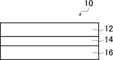
- FIG. 1 is a schematic cross-sectional view showing an example of the optical film of the present invention.
- the present invention will be described in detail.
- the description of the constituent elements described below may be based on a typical embodiment of the present invention, but the present invention is not limited to such an embodiment.
- the numerical range represented by using "-" means a range including the numerical values before and after "-" as the lower limit value and the upper limit value.
- a substance corresponding to each component may be used alone or in combination of two or more.
- the content of the component means the total content of the substances used in combination unless otherwise specified.
- the bonding direction of the divalent group (for example, -CO-NR-) described is not particularly limited unless the bonding position is specified, and for example, the formula (for example) described later will be used.
- D 1 in I) is -CO-NR-, if the position bonded to the G 1 side is * 1 and the position bonded to the Ar 1 side is * 2, D 1 is * 1. It may be -CO-NR- * 2 or * 1-NR-CO- * 2.
- the optically anisotropic layer of the present invention is an optical difference obtained by polymerizing a polymerizable liquid crystal composition containing a polymerizable liquid crystal compound (hereinafter, formally abbreviated as "the polymerizable liquid crystal composition of the present invention"). It is a square layer. Further, in the optically anisotropic layer of the present invention, when the amplitude value of each wavelength obtained by Fourier transforming the data of the three-dimensional surface roughness is L, the amplitude value L having a wavelength of 5.0 ⁇ m or more is 0. This is an optically anisotropic layer having an amplitude value L of 125 or more and a wavelength of 2.0 to 2.5 ⁇ m of 0.025 or less.
- the amplitude value L of each wavelength means a value calculated by the following procedure.
- -Measurement mode Phase mode-Complementation: Yes-Baseline correction: Yes-Objective lens magnification: 10 times
- FFT fast Fourier transformed
- the concentric amplitude distribution when the frequency F is set every 100 (1 / mm) is obtained.
- the wavelength is 5.0 ⁇ m
- F ⁇ 200 the amplitude value corresponds to the amplitude value L having a wavelength of 5.0 ⁇ m or more.
- the amplitude value of 400 ⁇ F ⁇ 500 corresponds to the amplitude value L having a wavelength of 2.0 to 2.5 ⁇ m.
- the amplitude value L of the wavelength 5.0 ⁇ m or more is 0.125 or more and the wavelength.
- an optically anisotropic layer having an amplitude value L of 2.0 to 2.5 ⁇ m of 0.025 or less the occurrence of haze is suppressed and the winding suitability is improved. This is not clear in detail, but the present inventors speculate as follows. First, it is considered that the surface of the optically anisotropic layer has a periodic uneven shape due to volume shrinkage when the polymerizable liquid crystal composition is polymerized.
- the amplitude value L having a wavelength of 5.0 ⁇ m or more is preferably 0.235 or more, and more preferably 0.235 or more and 0.600 or less, for the reason that the winding suitability is improved. ..
- the amplitude value L of the wavelength 2.0 to 2.5 ⁇ m is preferably 0.021 or less, preferably 0.001 or more and 0.021 or less, for the reason that the occurrence of haze is further suppressed. More preferably.
- the polymerizable liquid crystal composition of the present invention is immobilized in a smectic phase liquid crystal state because the contrast of the image display device having the optically anisotropic layer is good. Is preferable.
- the polymerizable liquid crystal compound contained in the polymerizable liquid crystal composition of the present invention is not particularly limited as long as it is a liquid crystal compound having a polymerizable group, and is preferably a liquid crystal compound having two or more polymerizable groups.
- the polymerizable group contained in the polymerizable crystal compound is not particularly limited, but a polymerizable group capable of radical polymerization or cationic polymerization is preferable.
- a known radically polymerizable group can be used, and suitable examples thereof include an acryloyloxy group and a methacryloyloxy group.
- the acryloyloxy group is generally faster in terms of polymerization rate, and the acryloyloxy group is preferable from the viewpoint of improving productivity, but the methacryloyloxy group can also be used as the polymerizable group in the same manner.
- a known cationically polymerizable group can be used, and specifically, an alicyclic ether group, a cyclic acetal group, a cyclic lactone group, a cyclic thioether group, a spiroorthoester group, and vinyloxy.
- the group can be mentioned.
- an alicyclic ether group or a vinyloxy group is preferable, and an epoxy group, an oxetanyl group, or a vinyloxy group is particularly preferable.
- particularly preferable polymerizable groups include polymerizable groups represented by any of the following formulas (P-1) to (P-20).
- liquid crystal compounds can be classified into rod-shaped type and disk-shaped type according to their shapes. Furthermore, there are low molecular weight and high molecular weight types, respectively.
- a polymer generally refers to a polymer having a degree of polymerization of 100 or more (Polymer Physics / Phase Transition Dynamics, Masao Doi, p. 2, Iwanami Shoten, 1992).
- any liquid crystal compound can be used, but it is preferable to use a rod-shaped liquid crystal compound or a discotic liquid crystal compound (disk-shaped liquid crystal compound). Two or more kinds of rod-shaped liquid crystal compounds, two or more kinds of disk-shaped liquid crystal compounds, or a mixture of a rod-shaped liquid crystal compound and a disk-shaped liquid crystal compound may be used.
- rod-shaped liquid crystal compound for example, those described in claim 1 of JP-A-11-513019 and paragraphs [0026] to [0098] of JP-A-2005-289980 can be preferably used, and discotics can be used.
- liquid crystal compound for example, those described in paragraphs [0020] to [0067] of JP2007-108732 and paragraphs [0013] to [0108] of JP2010-244038 can be preferably used. However, it is not limited to these.
- the polymerizable liquid crystal compound is preferably a polymerizable liquid crystal compound having reverse wavelength dispersibility (hereinafter, also abbreviated as “reverse dispersion liquid crystal compound”) for the reason of improving the optical compensatory property.
- reverse dispersion liquid crystal compound a polymerizable liquid crystal compound having reverse wavelength dispersibility
- the term "polymerizable liquid crystal compound having inverse wavelength dispersibility” as used herein refers to an in-plane retardation (Re) value at a specific wavelength (visible light range) of a retardation film produced using the same. When the measurement is performed, the Re value becomes equal or higher as the measurement wavelength becomes larger.
- Examples of the inversely dispersed liquid crystal compound include a compound represented by the following formula (I).
- a1, a2, g1 and g2 independently represent 0 or 1, respectively. However, at least one of a1 and g1 represents 1, and at least one of a2 and g2 represents 1. Further, in the above formula (I), q1 represents 1 or 2. Further, in the above formula (I), D 1 , D 2 , D 3 , D 4 , D 5 and D 6 are independently single-bonded or -CO-, -O-, -S-,-, respectively.
- R 1 ⁇ R 5 independently represents a hydrogen atom, a fluorine atom, or an alkyl group having 1 to 12 carbon atoms.
- a plurality of D 2 may each be the same or different.
- G 1 and G 2 each independently have an aromatic ring having 6 to 20 carbon atoms which may have a substituent or a carbon which may have a substituent.
- a 1 and A 2 are independently aromatic rings having 6 to 20 carbon atoms which may have a substituent, or carbons which may have a substituent.
- SP 1 and SP 2 are independently a single bond, a linear or branched alkylene group having 1 to 12 carbon atoms, or a linear chain having 1 to 12 carbon atoms.
- Q represents a substituent.
- L 1 and L 2 each independently represent a monovalent organic group, and at least one of L 1 and L 2 represents a polymerizable group.
- Ar is at least one polymerizable group of the formula If (Ar-3) an aromatic ring represented by the, L 1 and L 2 and L 3 and L 4 in formula (Ar-3) Represents.
- a1, a2, g1 and g2 are preferably 1 for the reason that the polymerizable liquid crystal composition of the present invention tends to show the liquid crystal state of the smectic phase. Further, it is preferable that both a1 and a2 are 0 and both g1 and g2 are 1 for the reason that the contrast of the image display device having the optically anisotropic layer is good.
- q1 is preferably 1.
- examples of the divalent linking group represented by one aspect of D 1 , D 2 , D 3 , D 4 , D 5 and D 6 include -CO-, -O-, and -CO-.
- R 1 , R 2 and R 5 independently represent a hydrogen atom, a fluorine atom, or an alkyl group having 1 to 12 carbon atoms. Of these, any of -CO-, -O-, and -CO-O- is preferable.
- examples of the aromatic ring having 6 to 20 carbon atoms represented by one aspect of G 1 and G 2 include an aromatic hydrocarbon ring such as a benzene ring, a naphthalene ring, an anthracene ring, and a phenanthroline ring.
- Aromatic heterocycles such as furan ring, pyrrole ring, thiophene ring, pyridine ring, thiazole ring, and benzothiazole ring; Of these, a benzene ring (for example, a 1,4-phenyl group) is preferable.
- the divalent alicyclic hydrocarbon group having 5 to 20 carbon atoms represented by one aspect of G 1 and G 2 is preferably a 5-membered ring or a 6-membered ring.
- the alicyclic hydrocarbon group may be saturated or unsaturated, but a saturated alicyclic hydrocarbon group is preferable.
- the divalent alicyclic hydrocarbon group represented by G 1 and G 2 for example, the description in paragraph [0078] of JP2012-21068A can be referred to, and this content is incorporated in the present specification. ..
- G 1 and G 2 in the above formula (I) are preferably cycloalkane rings for the reason that the contrast of the image display device having the optically anisotropic layer is good.
- the cycloalkane ring include a cyclohexane ring, a cyclopeptane ring, a cyclooctane ring, a cyclododecane ring, and a cyclododecane ring.
- a cyclohexane ring is preferred, a 1,4-cyclohexylene group is more preferred, and a trans-1,4-cyclohexylene group is even more preferred.
- G 1 and G 2 are designated as substituents which may be contained in an aromatic ring having 6 to 20 carbon atoms or a divalent alicyclic hydrocarbon group having 5 to 20 carbon atoms.
- Examples thereof include a group and an N-alkylcarbamate group, and among them, an alkyl group, an alkoxy group, an alkoxycarbonyl group, an alkylcarbonyloxy group, or a halogen atom is preferable.
- the alkyl group is preferably a linear, branched or cyclic alkyl group having 1 to 18 carbon atoms, and an alkyl group having 1 to 8 carbon atoms (for example, methyl group, ethyl group, propyl group, isopropyl group, n).
- alkoxy group an alkoxy group having 1 to 18 carbon atoms is preferable, an alkoxy group having 1 to 8 carbon atoms (for example, a methoxy group, an ethoxy group, an n-butoxy group, a methoxyethoxy group, etc.) is more preferable, and an alkoxy group having 1 carbon number is preferable.
- Alkoxy groups of ⁇ 4 are more preferable, and methoxy groups or ethoxy groups are particularly preferable.
- the alkoxycarbonyl group include a group in which an oxycarbonyl group (—O—CO— group) is bonded to the alkyl group exemplified above, and among them, a methoxycarbonyl group, an ethoxycarbonyl group, an n-propoxycarbonyl group or an isopropoxy.
- a carbonyl group is preferred, and a methoxycarbonyl group is more preferred.
- alkylcarbonyloxy group examples include a group in which a carbonyloxy group (-CO-O- group) is bonded to the alkyl group exemplified above, and among them, a methylcarbonyloxy group, an ethylcarbonyloxy group, and an n-propylcarbonyloxy group.
- a group or an isopropylcarbonyloxy group is preferable, and a methylcarbonyloxy group is more preferable.
- the halogen atom examples include a fluorine atom, a chlorine atom, a bromine atom and an iodine atom, and among them, a fluorine atom or a chlorine atom is preferable.
- the aromatic rings having 6 to 20 or more carbon atoms shown in one aspect of A 1 and A 2 are the same as those described in G 1 and G 2 in the above formula (I). Can be mentioned. Further, in the above formula (I), as the divalent alicyclic hydrocarbon group having 5 to 20 carbon atoms represented by one aspect of A 1 and A 2 , in G 1 and G 2 in the above formula (I). Examples are similar to those described. Regarding A 1 and A 2 , the substituent which the aromatic ring having 6 to 20 carbon atoms or the divalent alicyclic hydrocarbon group having 5 to 20 carbon atoms may have is the above formula (I). Examples include the same substituents that G 1 and G 2 may have.
- examples of the linear or branched alkylene group having 1 to 12 carbon atoms represented by one aspect of SP 1 and SP 2 include a methylene group, an ethylene group, a propylene group, a butylene group and a pentylene.
- a group, a hexylene group, a methylhexylene group, a heptylene group and the like are preferably mentioned.
- SP 1 and SP 2 have one or more of -CH 2- constituting a linear or branched alkylene group having 1 to 12 carbon atoms of -O-, -S-, and -NH.
- Examples of the monovalent organic group represented by L 1 and L 2 in the above formula (I) include an alkyl group, an aryl group, and a heteroaryl group.
- the alkyl group may be linear, branched or cyclic, but linear is preferred.
- the number of carbon atoms of the alkyl group is preferably 1 to 30, more preferably 1 to 20, and even more preferably 1 to 10.
- the aryl group may be monocyclic or polycyclic, but monocyclic is preferable.
- the aryl group preferably has 6 to 25 carbon atoms, more preferably 6 to 10 carbon atoms.
- the heteroaryl group may be monocyclic or polycyclic.
- the number of heteroatoms constituting the heteroaryl group is preferably 1 to 3.
- the hetero atom constituting the heteroaryl group is preferably a nitrogen atom, a sulfur atom, or an oxygen atom.
- the heteroaryl group preferably has 6 to 18 carbon atoms, more preferably 6 to 12 carbon atoms.
- the alkyl group, the aryl group and the heteroaryl group may be unsubstituted or have a substituent. Examples of the substituent include the same substituents that G 1 and G 2 in the above formula (I) may have.
- examples of the polymerizable group represented by at least one of L 1 and L 2 include those similar to the above-mentioned radical polymerization or cationically polymerizable polymerizable group, and among them, the above-mentioned formula (P).
- a polymerizable group represented by any one of -1) to (P-20) is preferably used.
- both L 1 and L 2 in the above formula (I) are polymerizable groups for the reason that the durability of the optically anisotropic layer is good, and an acryloyloxy group. Alternatively, it is more preferably a methacryloyloxy group.
- Ar represents any aromatic ring selected from the group consisting of the groups represented by the following formulas (Ar-1) to (Ar-7).
- q1 is 2, the plurality of Ars may be the same or different.
- * represents the bonding position with D 1 or D 2 in the above formula (I).
- Q 1 represents N or CH
- Q 2 represents -S-, -O-, or -N (R 6 )-
- R 6 is a hydrogen atom or Represents an alkyl group having 1 to 6 carbon atoms
- Y 1 is an aromatic hydrocarbon group having 6 to 12 carbon atoms which may have a substituent
- an aromatic group having 3 to 12 carbon atoms which may have a substituent A group heterocyclic group or an alicyclic hydrocarbon group having 6 to 20 carbon atoms which may have a substituent is represented, and one or more of -CH 2- constituting the alicyclic hydrocarbon group is -O. It may be substituted with ⁇ , —S— or ⁇ NH—.
- alkyl group having 1 to 6 carbon atoms indicated by R 6 include methyl group, ethyl group, propyl group, isopropyl group, n-butyl group, isobutyl group, sec-butyl group and tert-butyl.
- Examples include a group, an n-pentyl group, and an n-hexyl group.
- aromatic hydrocarbon group having 6 to 12 carbon atoms indicated by Y 1 include an aryl group such as a phenyl group, a 2,6-diethylphenyl group and a naphthyl group.
- Examples of the aromatic heterocyclic group having 3 to 12 carbon atoms indicated by Y 1 include heteroaryl groups such as a thienyl group, a thiazolyl group, a frill group and a pyridyl group.
- Examples of the alicyclic hydrocarbon group having 6 to 20 carbon atoms indicated by Y 1 include a cyclohexylene group, a cyclopentylene group, a norbornene group, and an adamantylene group.
- examples of the substituent that Y 1 may have include the same substituents that G 1 and G 2 in the above formula (I) may have.
- Z 1 , Z 2 and Z 3 are independently hydrogen atoms, monovalent aliphatic hydrocarbon groups having 1 to 20 carbon atoms, and carbons, respectively.
- Nitro group, -OR 7 , -NR 8 R 9 , -SR 10 , -COOR 11 , or -COR 12 where R 7 to R 12 are independent of hydrogen atoms or carbon atoms 1 to 6, respectively.
- Z 1 and Z 2 may be bonded to each other to form an aromatic ring.
- the monovalent aliphatic hydrocarbon group having 1 to 20 carbon atoms an alkyl group having 1 to 15 carbon atoms is preferable, an alkyl group having 1 to 8 carbon atoms is more preferable, and specifically, a methyl group and an ethyl group.
- Isopropyl group, tert-pentyl group (1,1-dimethylpropyl group), tert-butyl group, 1,1-dimethyl-3,3-dimethyl-butyl group are more preferable, and methyl group, ethyl group, tert-butyl group. Groups are particularly preferred.
- Examples of the monovalent alicyclic hydrocarbon group having 3 to 20 carbon atoms include a cyclopropyl group, a cyclobutyl group, a cyclopentyl group, a cyclohexyl group, a cycloheptyl group, a cyclooctyl group, a cyclodecyl group, a methylcyclohexyl group and an ethylcyclohexyl.
- Monocyclic saturated hydrocarbon groups such as groups; cyclobutenyl group, cyclopentenyl group, cyclohexenyl group, cycloheptenyl group, cyclooctenyl group, cyclodecenyl group, cyclopentadienyl group, cyclohexadienyl group, cyclooctadienyl group, cyclodeca Monocyclic unsaturated hydrocarbon groups such as diene; bicyclo [2.2.1] heptyl group, bicyclo [2.2.2] octyl group, tricyclo [5.2.1.0 2,6 ] decyl group, Tricyclo [3.3.1.1 3,7 ] decyl group, tetracyclo [6.2.1.1 3,6 .
- Polycyclic saturated hydrocarbon groups such as dodecyl group and adamantyl group; and the like.
- Specific examples of the monovalent aromatic hydrocarbon group having 6 to 20 carbon atoms include a phenyl group, a 2,6-diethylphenyl group, a naphthyl group, a biphenyl group and the like, and have 6 to 12 carbon atoms.
- Aryl groups particularly phenyl groups
- Specific examples of the monovalent aromatic heterocyclic group having 6 to 20 carbon atoms include a 4-pyridyl group, a 2-furyl group, a 2-thienyl group, a 2-pyrimidinyl group, and a 2-benzothiazolyl group. Can be mentioned.
- halogen atom examples include a fluorine atom, a chlorine atom, a bromine atom, an iodine atom and the like, and among them, a fluorine atom, a chlorine atom and a bromine atom are preferable.
- alkyl group having 1 to 6 carbon atoms represented by R 7 to R 10 include, for example, a methyl group, an ethyl group, a propyl group, an isopropyl group, an n-butyl group, an isobutyl group, and sec-butyl. Examples include groups, tert-butyl groups, n-pentyl groups, n-hexyl groups and the like.
- Z 1 and Z 2 may be bonded to each other to form an aromatic ring.
- Z 1 and Z 2 in the above formula (Ar-1) may be bonded to each other to form an aromatic ring.
- Examples of the structure of the case include a group represented by the following formula (Ar-1a).
- * represents the bonding position with D 1 or D 2 in the above formula (I).
- Q 1 , Q 2 and Y 1 are the same as those described in the above formula (Ar-1).
- a 3 and A 4 are each independently, -O -, - N (R 13) -, - S-, and from -CO- Represents a group selected from the group, where R 13 represents a hydrogen atom or a substituent.
- R 13 represents a hydrogen atom or a substituent.
- Examples of the substituent represented by R 13 include the same substituents that G 1 and G 2 in the above formula (I) may have.
- X represents a non-metal atom of Groups 14 to 16 to which a hydrogen atom or a substituent may be bonded.
- RC1 represents a hydrogen atom or a substituent. ] Can be mentioned.
- substituents include an alkyl group, an alkoxy group, an alkyl substituted alkoxy group, a cyclic alkyl group, an aryl group (for example, a phenyl group, a naphthyl group, etc.), a cyano group, an amino group, a nitro group, and an alkyl group.
- substituents include a carbonyl group, a sulfo group and a hydroxyl group.
- R 2 -, - CR 3 CR 4 -, - NR 5 -, or a divalent linking group formed from these two or more thereof,
- R 1 ⁇ R 5 are each independently a hydrogen atom, It represents a fluorine atom or an alkyl group having 1 to 12 carbon atoms.
- examples of the divalent linking group include the same groups as those described in D 1 , D 2 , D 3 , D 4 , D 5 and D 6 in the above formula (I).
- SP 3 and SP 4 are independently a single bond, a linear or branched alkylene group having 1 to 12 carbon atoms, or a direct group having 1 to 12 carbon atoms.
- Examples of the substituent include the same substituents that G 1 and G 2 in the above formula (I) may have.
- examples of the alkylene group include the same groups as those described in SP 1 and SP 2 in the above formula (I).
- L 3 and L 4 independently represent monovalent organic groups, respectively, and at least 1 of L 3 and L 4 and L 1 and L 2 in the above formula (I).
- the monovalent organic group include those similar to those described in L 1 and L 2 in the above formula (I).
- the polymerizable group the same group as the above-mentioned radical polymerization or cationically polymerizable polymerizable group can be mentioned, and among them, it is represented by any of the above-mentioned formulas (P-1) to (P-20). Polymerizable groups are preferred.
- Ax has at least one aromatic ring selected from the group consisting of an aromatic hydrocarbon ring and an aromatic heterocycle, and has 2 to 30 carbon atoms. Represents an organic group.
- Ay is a hydrogen atom, an alkyl group having 1 to 12 carbon atoms which may have a substituent, or an aromatic hydrocarbon ring and aromatic. Represents an organic group having 2 to 30 carbon atoms and having at least one aromatic ring selected from the group consisting of group heterocycles.
- the aromatic ring in Ax and Ay may have a substituent, or Ax and Ay may be bonded to form a ring.
- Q 3 represents a hydrogen atom or an alkyl group having 1 to 6 carbon atoms which may have a substituent.
- Examples of Ax and Ay include those described in paragraphs [0039] to [0995] of International Publication No. 2014/010325.
- the alkyl group of Q 3 is 1 to 20 carbon atoms shown, specifically, for example, a methyl group, an ethyl group, a propyl group, an isopropyl group, n- butyl group, isobutyl group, sec- butyl group, tert -Butyl group, n-pentyl group, n-hexyl group and the like can be mentioned, and examples of the substituent are the same as the substituents that G 1 and G 2 in the above formula (I) may have. Can be mentioned.
- Examples of the compound represented by the above formula (I) include compounds represented by the general formula (1) described in JP-A-2010-084032 (particularly, those described in paragraph numbers [0067] to [0073].
- K side chain structure
- “*" shown in the side chain structure of K represents the bonding position with the aromatic ring.
- the groups adjacent to the acryloyloxy group and the methacryloyl group are propylene groups (methyl groups are ethylene groups, respectively). It represents a substituted group) and represents a mixture of positional isomers with different methyl group positions.
- the polymerizable liquid crystal compound is preferably a compound that exhibits a liquid crystal state of the smectic phase because the contrast of the image display device having the optically anisotropic layer is good.
- the polymerizable liquid crystal composition of the present invention has one polymerizable group because the generation of haze in the optically anisotropic layer is further suppressed and the contrast of the image display device having the optically anisotropic layer is improved. Moreover, it preferably contains a monofunctional compound having two or more ring structures of at least one selected from the group consisting of aromatic rings or alicyclic rings.
- examples of the polymerizable group contained in the monofunctional compound include those similar to the radical polymerization or cationically polymerizable polymerizable group described in the above-mentioned polymerizable liquid crystal compound, and among them, the above-mentioned formula (P-1). )-(P-20), the polymerizable group represented by any of (P-20) is preferably mentioned.
- examples of the aromatic ring include an aromatic ring having 6 to 20 carbon atoms which may have a substituent, and specifically, benzene.
- Aromatic hydrocarbon rings such as ring, naphthalene ring, anthracene ring, and phenanthroline ring; furan ring, thiophene ring, pyrrole ring, oxazole ring, isooxazole ring, oxaziazole ring, thiazole ring, isothiazole ring
- Aromatic heterocycles such as thiasiazole ring, imidazole ring, pyrazole ring, triazole ring, flazan ring, tetrazole ring, pyridine ring, pyridazine ring, pyrimidine ring, pyrazine ring, triazine ring, tetrazine ring, and benzothiazole ring;
- Aromatic heterocycles such as thiasiazol
- Examples of the alicyclic ring include a cycloalkane ring which may have a substituent, and specific examples thereof include a cyclohexane ring, a cyclopeptane ring, a cyclooctane ring, a cyclododecane ring, and a cyclododecane ring. Of these, a cyclohexane ring is preferable.
- Examples of the substituent include the same substituents that G 1 and G 2 in the above formula (I) described in the above-mentioned polymerizable liquid crystal compound may have.
- the monofunctional compound is substituted with a polymerizable group because the occurrence of haze in the optically anisotropic layer is further suppressed and the contrast of the image display device having the optically anisotropic layer is improved.
- It has an aromatic ring which may have a group, a polymerizable group constitutes one end of the molecule, and an aromatic ring or a substituent which may have an aromatic ring is the other end of the molecule. It is preferable that it is a compound constituting the above.
- one end and the other end refer to the starting atom and the ending atom for which the maximum number of atoms is calculated when the atoms on the bond of the compound are connected at the shortest distance, respectively, and they are hydrogen atoms.
- a polymerizable group when a polymerizable group constitutes a terminal, it means that the polymerizable group contains a terminal atom, and when an aromatic ring constitutes a terminal, it means that the aromatic ring contains a terminal atom, and a substituent is a terminal. Consists of means that the substituent contains a terminal atom.
- the monofunctional compound is preferably a compound represented by the following formula (II) for the reason that the planar condition of the optically anisotropic layer is improved.
- a3 and g3 each independently represent an integer of 0 to 2. However, a3 and g3 represent integers of 1 to 3 in total.
- R 2 -, - CR 3 CR 4 -, - NR 5 -, or a divalent linking group formed from these two or more thereof
- R 1 ⁇ R 5 are each independently a hydrogen atom , Fluorine atom, or an alkyl group having 1 to 12 carbon atoms.
- G 3 is an aromatic ring of 6 to 20 carbon atoms which may have a substituent, or carbon atoms which may have a substituent group 5 to 20 bivalent
- g3 is 2, a plurality of G 3 are, may each be the same or different.
- a 5 is an aromatic ring of 6 to 20 carbon atoms which may have a substituent, or carbon atoms which may have a substituent group 5 to 20 bivalent
- the plurality of A 5, may each be the same or different.
- SP 5 has a single bond, a linear or branched alkylene group having 1 to 12 carbon atoms, or a linear or branched alkylene group having 1 to 12 carbon atoms.
- One or more of the constituent -CH 2- represents a divalent linking group substituted with -O-, -S-, -NH-, -N (Q)-, or -CO-, where Q represents a divalent linking group.
- Q represents a divalent linking group.
- L 5 represents a polymerizable group.
- M represents an aromatic ring which may have a substituent.
- a3 and g3 are preferably 1 because the polymerizable liquid crystal composition of the present invention tends to show the liquid crystal state of the smectic phase.
- the divalent linking group represented by one aspect of D 9 , D 10 and D 11 in the above formula (II) for example, the divalent linking group represented by one aspect such as D 1 in the above formula (I).
- D 9 , D 10 and D 11 in the above formula (I) for example, the divalent linking group represented by one aspect such as D 1 in the above formula (I).
- D 1 in the above formula (I) The same as those exemplified as above are mentioned, and among them, any of -CO-, -O-, and -CO-O- is preferable.
- the aromatic ring of one embodiment 6 to 20 carbon atoms shown in G 3 for example, of the formula (I) having 6 to carbon atoms indicated by an embodiment such as G 1 in 20 aromatic ring Among them, a benzene ring (for example, a 1,4-phenyl group) is preferable.
- Examples of the divalent alicyclic hydrocarbon group of No. 5 to 20 include those similar to those exemplified, among which the cycloalkane ring is preferable, the cyclohexane ring is more preferable, and the 1,4-cyclohexylene group is further preferable. , Trans-1,4-cyclohexylene groups are particularly preferred.
- the G 3 examples of the divalent alicyclic hydrocarbon group substituents which may be possessed by the aromatic ring or having 5 to 20 carbon atoms of 6 to 20 carbon atoms is, above Examples thereof include the same substituents that G 1 and G 2 in the above formula (I) described in the above-mentioned polymerizable liquid crystal compound may have.
- the aromatic ring having 6 to 20 or more carbon atoms indicated by an aspect of A 5 include the same as those described in G 1 and G 2 in the formula (I).
- the divalent alicyclic hydrocarbon group of one embodiment is 5 to 20 carbon atoms shown in the A 5, those described in G 1 and G 2 in the formula (I) The same can be mentioned.
- the polymerizable liquid crystal compounds described above in the aromatic ring or having 5 to 20 carbon atoms of 6 to 20 carbon atoms described Examples thereof include the same substituents that G 1 and G 2 in the above formula (I) may have.
- examples of the polymerizable group represented by L 5 include those similar to the radical polymerization or cationically polymerizable polymerizable group described in the above-mentioned polymerizable liquid crystal compound, and among them, the above formula.
- Preferred examples include the polymerizable group represented by any one of (P-1) to (P-20).
- the aromatic ring represented by M for example, include aromatic ring having 6 to 20 carbon atoms, specifically, the carbon indicated by an embodiment such as G 1 in the formula (I)
- Examples of the aromatic ring of No. 6 to 20 include those similar to those exemplified, and among them, a benzene ring (for example, a 1,4-phenyl group) is preferable.
- the substituents that the aromatic ring may have are the substituents that G 1 and G 2 in the above formula (I) described in the above-mentioned polymerizable liquid crystal compound may have. Similar things can be mentioned.
- Specific examples of the compound represented by the above formula (II) include compounds represented by the following formulas (TN-1) to (TN-21).
- the content of the monofunctional compound when the monofunctional compound is contained is described above. It is preferably 4 to 20 parts by mass, and more preferably 8 to 16 parts by mass with respect to 100 parts by mass of the polymerized liquid crystal compound.
- the atomic number D1 of the above-mentioned polymerizable liquid crystal compound and the above-mentioned monofunctional compound are used. It is preferable that the number of atoms D2 satisfies the relationship of the following formula (1), and more preferably the relationship of the following formula (2) is satisfied. 0.35 ⁇ D2 / D1 ⁇ 0.45 ... (1) 0.35 ⁇ D2 / D1 ⁇ 0.45 ...
- the number of atoms represents the number of atoms on the bond connecting one end of the compound and the other end at the shortest distance, and does not include a hydrogen atom. Further, one end and the other end refer to the starting atom and the ending atom for which the maximum number of atoms is calculated when the atoms on the bond of the compound are connected at the shortest distance, respectively, and the hydrogen atom is It shall not be included.
- the polymerizable liquid crystal composition of the present invention preferably contains a polymerization initiator.
- the polymerization initiator used is preferably a photopolymerization initiator capable of initiating a polymerization reaction by irradiation with ultraviolet rays.
- Examples of the photopolymerization initiator include ⁇ -carbonyl compounds (described in US Pat. No. 2,376,661 and US Pat. No. 2,376,670), acidoin ethers (described in US Pat. No. 2,448,828), and ⁇ -hydrogen-substituted fragrances.
- Group acidoine compounds described in US Pat. No. 2722512
- polynuclear quinone compounds described in US Pat. Nos.
- the polymerization initiator is preferably an oxime type polymerization initiator, and specific examples thereof are described in paragraphs [0049] to [0052] of International Publication No. 2017/170443. Agents are mentioned.
- the polymerizable liquid crystal composition of the present invention preferably contains a solvent from the viewpoint of workability for forming the optically anisotropic layer of the present invention.
- a solvent from the viewpoint of workability for forming the optically anisotropic layer of the present invention.
- the solvent include ketones (for example, acetone, 2-butanone, methylisobutylketone, cyclohexanone, cyclopentanone, etc.), ethers (for example, dioxane, tetrahydrofuran, etc.), and aliphatic hydrocarbons.
- the polymerizable liquid crystal composition of the present invention preferably contains a leveling agent from the viewpoint of keeping the surface of the optically anisotropic layer of the present invention smooth and facilitating orientation control.
- a leveling agent is preferably a fluorine-based leveling agent or a silicon-based leveling agent because it has a high leveling effect on the amount of addition, and a fluorine-based leveling agent from the viewpoint of less likely to cause crying (bloom, bleed). Is more preferable.
- Specific examples of the leveling agent include the compounds described in paragraphs [0079] to [0102] of JP-A-2007-069471, and the general formulas described in JP-A-2013-047204.
- the polymerizable liquid crystal composition of the present invention may contain an orientation control agent, if necessary.
- the orientation control agent can form various orientation states such as homeotropic orientation (vertical orientation), tilt orientation, hybrid orientation, and cholesteric orientation in addition to homogenius orientation, and can make a specific orientation state more uniform and more uniform. It can be realized by precise control.
- a low-molecular-weight orientation control agent or a high-molecular-weight orientation control agent can be used as the orientation control agent that promotes homogenous orientation.
- the low-molecular-weight orientation control agent include paragraphs [0009] to [0083] of JP-A-2002-20363, paragraphs [0111]-[0120] of JP-A-2006-106662, and JP-A-2012.
- paragraphs [0021] to [0029] of Japanese Patent Application Laid-Open No. 211306 can be referred to, and this content is incorporated in the present specification.
- orientation control agent for forming or promoting homeotropic orientation examples include boronic acid compounds and onium salt compounds. Specifically, paragraphs [0023] to [0032] of JP-A-2008-225281. , Paragraphs [0052] to [0058] of JP2012-208397A, paragraphs [0024] to [0055] of JP2008-026730, and [0043] to [0055] of JP2016-193869. The compounds described in paragraphs and the like can be taken into account, the contents of which are incorporated herein by reference.
- the cholesteric orientation can be realized by adding a chiral agent to the polymerizable liquid crystal composition of the present invention, and the turning direction of the cholesteric orientation can be controlled by the direction of the chiral property.
- the pitch of the cholesteric orientation can be controlled according to the orientation regulating force of the chiral agent.
- the content is preferably 0.01 to 10% by mass, more preferably 0.05 to 5% by mass, based on the total solid content mass in the composition.
- the content is in this range, a uniform and highly transparent cured product can be obtained without precipitation, phase separation, orientation defects, etc., while achieving the desired orientation state.
- the polymerizable liquid crystal composition of the present invention may contain components other than those described above, and examples thereof include surfactants, tilt angle control agents, orientation aids, plasticizers, and cross-linking agents.
- the optically anisotropic layer of the present invention is a cured product obtained by polymerizing the above-mentioned polymerizable liquid crystal composition of the present invention.
- the cured product can be formed on an arbitrary support in the optical film of the present invention described later or on a polarizer in the polarizing plate of the present invention described later.
- Examples of the method for forming the cured product include a method of using the above-mentioned polymerizable liquid crystal composition of the present invention to achieve a desired orientation state and then immobilizing the cured product by polymerization.
- the polymerization conditions are not particularly limited, but it is preferable to use ultraviolet rays in the polymerization by light irradiation.
- the irradiation amount is preferably 10 mJ / cm 2 to 50 J / cm 2 , more preferably 20 mJ / cm 2 to 5 J / cm 2 , and even more preferably 30 mJ / cm 2 to 3 J / cm 2. , 50 to 1000 mJ / cm 2 is particularly preferable. Further, in order to promote the polymerization reaction, it may be carried out under heating conditions.
- the above-mentioned polymerizable liquid crystal composition of the present invention is a composition showing a liquid crystal state of a smectic phase, the phase transition temperature (N—Sm transition temperature) from the nematic phase to the smectic phase and the time of UV irradiation It is preferable to carry out the polymerization at a temperature at which the difference from the temperature (curing temperature) of the above is less than 20 ° C.
- the optically anisotropic layer of the present invention is preferably an optically anisotropic layer satisfying the following formula (III). 0.50 ⁇ Re (450) / Re (550) ⁇ 1.00 ... (III)
- Re (450) represents the in-plane lettering of the optically anisotropic layer at a wavelength of 450 nm
- Re (550) represents the in-plane letter of the optically anisotropic layer at a wavelength of 550 nm.
- an optically anisotropic layer is preferably a positive A plate or a positive C plate, and more preferably a positive A plate.
- the positive A plate (positive A plate) and the positive C plate (positive C plate) are defined as follows.
- the refractive index in the slow axis direction in the film plane (the direction in which the refractive index in the plane is maximized) is nx
- the refractive index in the direction orthogonal to the slow phase axis in the plane in the plane is ny
- the refraction in the thickness direction is nz
- the positive A plate satisfies the relation of the formula (A1)
- the positive C plate satisfies the relation of the formula (C1).
- the positive A plate shows a positive value for Rth
- the positive C plate shows a negative value for Rth.
- ⁇ includes not only the case where both are completely the same, but also the case where both are substantially the same. “Substantially the same” means that, for example, in the positive A plate, (ny-nz) ⁇ d (where d is the thickness of the film) is -10 to 10 nm, preferably -5 to 5 nm. It is included in “ny ⁇ nz”, and when (nx-nz) xd is -10 to 10 nm, preferably -5 to 5 nm, it is also included in "nx ⁇ nz”.
- (nx ⁇ ny) ⁇ d (where d is the thickness of the film) is 0 to 10 nm, preferably 0 to 5 nm, it is also included in “nx ⁇ ny”.
- Re (550) is preferably 100 to 180 nm, more preferably 120 to 160 nm, and 130 to 150 nm from the viewpoint of functioning as a ⁇ / 4 plate. It is more preferably 130 to 140 nm, and particularly preferably 130 to 140 nm.
- the " ⁇ / 4 plate” is a plate having a ⁇ / 4 function, and specifically, a function of converting linearly polarized light having a specific wavelength into circularly polarized light (or converting circularly polarized light into linearly polarized light). It is a plate having.
- the optical film of the present invention is an optical film having the optically anisotropic layer of the present invention.
- FIG. 1 is a schematic cross-sectional view showing an example of the optical film of the present invention. Note that FIG. 1 is a schematic view, and the thickness relationship and positional relationship of each layer do not always match the actual ones, and the support and the alignment film shown in FIG. 1 are all arbitrary constituent members.
- the optical film 10 shown in FIG. 1 has a support 16, an alignment film 14, and an optically anisotropic layer 12 as a cured product in this order. Further, the optically anisotropic layer 12 may be a laminate of two or more different optically anisotropic layers.
- the polarizing plate of the present invention described later is used as a circular polarizing plate, or when the optical film of the present invention is used as an optical compensation film for an IPS type or FFS type liquid crystal display device, a positive A plate and a positive C are used. It is preferably a laminate of plates. Further, the optically anisotropic layer may be peeled off from the support and the optically anisotropic layer alone may be used as an optical film.
- various members used in the optical film of the present invention will be described in detail.
- optically anisotropic layer of the optical film of the present invention is the above-mentioned optically anisotropic layer of the present invention.
- the thickness of the optically anisotropic layer is not particularly limited, but is preferably 0.1 to 10 ⁇ m, more preferably 0.5 to 5 ⁇ m.
- the optical film of the present invention may have a support as a base material for forming an optically anisotropic layer.
- a support is preferably transparent, and specifically, the light transmittance is preferably 80% or more.
- Examples of such a support include a glass substrate and a polymer film, and examples of the polymer film material include a cellulose-based polymer; an acrylic-based polymer having an acrylic acid ester polymer such as polymethylmethacrylate and a lactone ring-containing polymer.
- the thickness of the support is not particularly limited, but is preferably 5 to 60 ⁇ m, more preferably 5 to 40 ⁇ m.
- the optical film of the present invention has any of the above-mentioned supports, it is preferable that the optical film has an alignment film between the support and the optically anisotropic layer.
- the support described above may also serve as an alignment film.
- the alignment film generally contains a polymer as a main component.
- the polymer material for an alignment film has been described in a large number of documents, and a large number of commercially available products are available.
- the polymer material used in the present invention is preferably polyvinyl alcohol or polyimide, or a derivative thereof. Particularly modified or unmodified polyvinyl alcohol is preferable.
- the alignment film for example, the alignment film described in International Publication No. 01/88574, p. 43, p. 24 to p. 49, p. 8; ], And the like; a liquid crystal alignment film formed by the liquid crystal alignment agent described in Japanese Patent Application Laid-Open No. 2012-155308; and the like.
- a photoalignment film as the alignment film because it is possible to prevent surface deterioration by not contacting the surface of the alignment film when forming the alignment film.
- the photoalignment film is not particularly limited, but is a polymer material such as a polyamide compound or a polyimide compound described in paragraphs [0024] to [0043] of International Publication No. 2005/096041; A liquid crystal alignment film formed by a liquid crystal alignment agent having a photo-oriented group; a trade name LPP-JP265CP manufactured by Polyimide, Inc. can be used.
- the thickness of the alignment film is not particularly limited, but from the viewpoint of alleviating the surface irregularities that may exist on the support and forming an optically anisotropic layer having a uniform film thickness, 0. It is preferably 01 to 10 ⁇ m, more preferably 0.01 to 1 ⁇ m, and even more preferably 0.01 to 0.5 ⁇ m.
- the optical film of the present invention preferably contains an ultraviolet (UV) absorber in consideration of the influence of external light (particularly ultraviolet rays).
- the ultraviolet absorber may be contained in the optically anisotropic layer of the present invention, or may be contained in a member other than the optically anisotropic layer constituting the optical film of the present invention.
- a support is preferably mentioned.
- the ultraviolet absorber any conventionally known one capable of exhibiting ultraviolet absorption can be used.
- a benzotriazole-based or hydroxyphenyltriazine-based ultraviolet absorber may be used from the viewpoint of obtaining the ultraviolet absorbing ability (ultraviolet blocking ability) used in an image display device because of its high ultraviolet absorbing ability. preferable.
- two or more kinds of ultraviolet absorbers having different maximum absorption wavelengths can be used in combination.
- Specific examples of the ultraviolet absorber include compounds described in paragraphs [0258] to [0259] of JP2012-18395, paragraphs [0055] to [0105] of JP2007-72163. Examples thereof include the compounds described in.
- Tinuvin400, Tinuvin405, Tinuvin460, Tinuvin477, Tinuvin479, Tinuvin1577 (all manufactured by BASF) and the like can be used.
- the polarizing plate of the present invention has the above-mentioned optical film of the present invention and a polarizer. Further, the polarizing plate of the present invention can be used as a circular polarizing plate when the optically anisotropic layer of the present invention described above is a ⁇ / 4 plate (positive A plate). When the polarizing plate of the present invention is used as a circular polarizing plate, the optically anisotropic layer of the present invention described above is a ⁇ / 4 plate (positive A plate), and the slow axis of the ⁇ / 4 plate and the polarizer described later are used.
- the angle formed by the absorption shaft is preferably 30 to 60 °, more preferably 40 to 50 °, further preferably 42 to 48 °, and particularly preferably 45 °.
- the polarizing plate of the present invention can also be used as an optical compensation film for an IPS type or FFS type liquid crystal display device.
- the above-mentioned optically anisotropic layer of the present invention is used at least one of a laminate of a positive A plate and a positive C plate.
- the angle formed by the slow axis of the positive A plate layer and the absorption axis of the polarizer described later is orthogonal or parallel, and specifically, the slow axis of the positive A plate layer and the slow axis of the positive A plate layer. It is more preferable that the angle formed by the polarizing element with the absorption axis, which will be described later, is 0 to 5 ° or 85 to 95 °.
- the "slow-phase axis" of the ⁇ / 4 plate or the positive A plate layer means the direction in which the refractive index is maximized in the plane of the ⁇ / 4 plate or the positive A plate layer, and the "absorption axis" of the polarizer. "" Means the direction of the highest absorbance.
- the polarizer of the polarizing plate of the present invention is not particularly limited as long as it is a member having a function of converting light into specific linearly polarized light, and conventionally known absorption type polarizers and reflection type polarizers can be used. ..
- absorption type polarizer an iodine-based polarizer, a dye-based polarizer using a dichroic dye, a polyene-based polarizer, and the like are used. Iodine-based polarized light and dye-based polarized light include coated and stretched polarized light, and both can be applied.
- the reflective polarizer a polarizer in which thin films having different birefringences are laminated, a wire grid type polarizer, a polarizer in which a cholesteric liquid crystal having a selective reflection region and a 1/4 wave plate are combined, and the like are used.
- polyvinyl alcohol-based resin polymer containing as a repeating unit -CH 2 -CHOH-, in particular, polyvinyl alcohol and ethylene - at least selected from the group consisting of vinyl alcohol copolymer It is preferable that the polymer contains one).
- the thickness of the polarizer is not particularly limited, but is preferably 3 ⁇ m to 60 ⁇ m, more preferably 3 ⁇ m to 30 ⁇ m, and even more preferably 3 ⁇ m to 10 ⁇ m.
- an adhesive layer may be arranged between the optically anisotropic layer in the optical film of the present invention and the polarizer.
- G') represents a substance having a value of 0.001 to 1.5, and includes so-called adhesives, substances that easily creep, and the like.
- Examples of the pressure-sensitive adhesive that can be used in the present invention include, but are not limited to, a polyvinyl alcohol-based pressure-sensitive adhesive.
- an adhesive layer may be arranged between the optically anisotropic layer in the optical film of the present invention and the polarizer.
- a curable adhesive composition that is cured by irradiation with active energy rays or heating is preferable.
- the curable adhesive composition include a curable adhesive composition containing a cationically polymerizable compound and a curable adhesive composition containing a radically polymerizable compound.
- the thickness of the adhesive layer is preferably 0.01 to 20 ⁇ m, more preferably 0.01 to 10 ⁇ m, and even more preferably 0.05 to 5 ⁇ m. When the thickness of the adhesive layer is within this range, floating or peeling does not occur between the laminated protective layer or the optically anisotropic layer and the polarizer, and a practically acceptable adhesive force can be obtained.
- the image display device of the present invention is an image display device having the optical film of the present invention or the polarizing plate of the present invention.
- the display element used in the image display device of the present invention is not particularly limited, and examples thereof include a liquid crystal cell, an organic electroluminescence (hereinafter abbreviated as “EL”) display panel, and a plasma display panel.
- EL organic electroluminescence
- a liquid crystal cell and an organic EL display panel are preferable, and a liquid crystal cell is more preferable.
- the image display device of the present invention is preferably a liquid crystal display device using a liquid crystal cell as a display element and an organic EL display device using an organic EL display panel as a display element, and the liquid crystal display device is preferable. More preferred.
- the liquid crystal display device which is an example of the image display device of the present invention is a liquid crystal display device having the above-mentioned polarizing plate of the present invention and a liquid crystal cell.
- the polarizing plate of the present invention among the polarizing plates provided on both sides of the liquid crystal cell, it is preferable to use the polarizing plate of the present invention as the polarizing plate on the front side, and the polarizing plate of the present invention as the polarizing plate on the front side and the rear side. Is more preferable to use.
- the liquid crystal cells constituting the liquid crystal display device will be described in detail below.
- the liquid crystal cell used in the liquid crystal display device is a VA (Vertical Element) mode, an OCB (Optically Compensated Bend) mode, an IPS (In-Plane-Switching) mode, an FFS (Fringe-Field-Switching) mode, or a TN (Twisted) mode.
- VA Vertical Element
- OCB Optically Compensated Bend
- IPS In-Plane-Switching
- FFS Feringe-Field-Switching
- TN Transmission-Field-Switching
- the Nematic mode is preferred, but is not limited to these.
- the rod-shaped liquid crystal molecules are substantially horizontally oriented when no voltage is applied, and are further twisted to 60 to 120 °.
- the TN mode liquid crystal cell is most often used as a color TFT liquid crystal display device, and has been described in many documents.
- the rod-shaped liquid crystal molecules are substantially vertically oriented when no voltage is applied.
- a VA mode liquid crystal cell in a narrow sense in which rod-shaped liquid crystal molecules are oriented substantially vertically when no voltage is applied and substantially horizontally when a voltage is applied Japanese Patent Laid-Open No. 2-.
- Liquid crystal cells in a mode in which rod-shaped liquid crystal molecules are substantially vertically oriented when no voltage is applied and twisted and multi-domain oriented when a voltage is applied. (1998)) and (4) SURVIVAL mode liquid crystal cells (announced at LCD International 98) are included. Further, it may be any of PVA (Patternized Vertical Alignment) type, optical alignment type (Optical Alignment), and PSA (Polymer-Sustained Alignment). Details of these modes are described in Japanese Patent Application Laid-Open No. 2006-215326 and Japanese Patent Application Laid-Open No. 2008-538819.
- the rod-shaped liquid crystal molecules are oriented substantially parallel to the substrate, and the liquid crystal molecules respond in a plane by applying an electric field parallel to the substrate surface.
- the display is black when no electric field is applied, and the absorption axes of the pair of upper and lower polarizing plates are orthogonal to each other.
- Methods for reducing leakage light when displaying black in an oblique direction and improving the viewing angle by using an optical compensation sheet are described in JP-A-10-54982, JP-A-11-202323, and JP-A-9-292522. It is disclosed in JP-A-11-133408, JP-A-11-305217, JP-A-10-307291, and the like.
- Organic EL display device examples include, from the visual side, a ⁇ / 4 plate (positive A plate) composed of a polarizer, an optically anisotropic layer of the present invention, and an organic EL.
- a mode in which the display panel and the display panel are provided in this order is preferably mentioned.
- the organic EL display panel is a display panel configured by using an organic EL element formed by sandwiching an organic light emitting layer (organic electroluminescence layer) between electrodes (between a cathode and an anode).
- the configuration of the organic EL display panel is not particularly limited, and a known configuration is adopted.
- Matte solution ⁇ -Silica particles with an average particle size of 20 nm (AEROSIL R972, manufactured by Nippon Aerosil Co., Ltd.) 2 parts by mass-Methylene chloride (first solvent) 76 parts by mass-Methanol (second solvent) 11 parts by mass-Core layer cellulose acylate dope 11 1 part by mass ⁇
- the curable composition 1 for hard coating is applied onto the surface of the protective film 1 prepared above, then dried at 100 ° C. for 60 seconds, and UV is 1.5 kW under the condition of nitrogen 0.1% or less. , 300 mJ was irradiated and cured to prepare a protective film 1 with a hard coat layer having a hard coat layer having a thickness of 5 ⁇ m. The film thickness of the hard coat layer was adjusted by using a slot die and adjusting the coating amount by the die coating method.
- a polarizing plate 1 with a single-sided protective film (hereinafter, also simply referred to as “polarizing plate 1”) was produced by laminating by roll-to-roll so that the polarization axis and the longitudinal direction of the film were orthogonal to each other. At this time, the protective film was bonded so that the cellulose acylate film side was on the polarizer side.
- polarizing plate 2 with single-sided protective film [Preparation of polarizing plate 2 with single-sided protective film]
- the polarizing plate 2 with a single-sided protective film (hereinafter, also simply referred to as “polarizing plate 2”) was produced in the same manner except that the hard coat layer was not provided on the surface of the protective film 1.
- each liquid crystal display device was manufactured by using the polarizing plate 1 on the visual recognition side and the polarizing plate 2 on the backlight side.
- Polyester (number average molecular weight 800)
- Matte solution ⁇ -Silica particles with an average particle size of 20 nm (AEROSIL R972, manufactured by Nippon Aerosil Co., Ltd.) 2 parts by mass-Methylene chloride (first solvent) 76 parts by mass-Methanol (second solvent) 11 parts by mass-Core layer cellulose acylate dope 1 part by mass ⁇
- ⁇ Preparation of protective film 2> After filtering the core layer cellulose acylate dope 2 and the outer layer cellulose acylate dope 2 with a filter paper having an average pore diameter of 34 ⁇ m and a sintered metal filter having an average pore diameter of 10 ⁇ m, the core layer cellulose acylate dope 2 and outer layer cellulose on both sides thereof are filtered. Three layers of acylate dope 2 were simultaneously cast on a drum at 20 ° C. from the casting port (band casting machine). Next, with the solvent content of the film on the drum being approximately 20% by mass, the film was peeled off from the drum, both ends in the width direction of the film were fixed with tenter clips, and the film was stretched laterally at a stretching ratio of 1.1 times.
- the obtained film was further dried by transporting it between the rolls of the heat treatment apparatus to prepare a cellulose acylate film 2 having a film thickness of 40 ⁇ m, which was used as a protective film 2.
- composition for forming an optically anisotropic layer having the following composition was prepared.
- Composition for forming an optically anisotropic layer 1 ⁇ -The following polymerizable liquid crystal compound S1 42.00 parts by mass-The following polymerizable liquid crystal compound S2 42.00 parts by mass-The following polyfunctional polymerizable compound R1 4.00 parts by mass-The following monofunctional compound T1 12.00 parts by mass-The following Polymerization initiator B1 0.50 parts by mass, following leveling agent P1 0.15 parts by mass, high solve MTEM (manufactured by Toho Chemical Industry Co., Ltd.) 2.00 parts by mass, NK ester A-200 (manufactured by Shin-Nakamura Chemical Industry Co., Ltd.) 1.
- the group adjacent to the acryloyloxy group of the polymerizable liquid crystal compounds S1 and S2 below represents a propylene group (a group in which the methyl group is replaced with an ethylene group), and the polymerizable liquid crystal compounds S1 and S2 below represent the positions of the methyl groups. Represents a mixture of different positional isomers.
- a die coating method using the slot die described in Example 1 of Japanese Patent Application Laid-Open No. 2006-122889 was performed on one surface of the produced protective film 2 by applying the photoalignment film forming material prepared above to a transport speed of 30 m / min. And dried at 120 ° C. for 1 minute to remove the solvent. Then, by irradiating with polarized ultraviolet rays (10 mJ / cm 2 , using an ultrahigh pressure mercury lamp), a photoalignment film 1 having a thickness of 0.3 ⁇ m was formed.
- the composition 1 for forming an optically anisotropic layer prepared above was applied on the photoalignment film 1 with a spin coater so that the film thickness after drying was 2.5 ⁇ m. After coating, it is heated for 30 seconds in a temperature range indicating the liquid crystal state of the nematic phase, cooled to a temperature 23 ° C. lower than the phase transition temperature from the nematic phase to the smectic phase, and then UV-irradiated (300 mJ / cm 2) at that temperature. ) was carried out to prepare an optically anisotropic layer 1 immobilized in a liquid crystal state of the smectic phase, and an optical film 1 was obtained.
- Example 5 shows the difference between the polymerizable liquid crystal compound, the monofunctional compound, the polymerization initiator, and the phase transition temperature (N—Sm transition temperature) from the nematic phase to the smectic phase and the temperature during UV irradiation (curing temperature).
- An optically anisotropic layer was prepared by the same method as in Example 1 except that the one shown was changed to obtain an optical film.
- UV irradiation was performed at a temperature higher than the phase transition temperature from the nematic phase to the smectic phase, specifically, at a temperature 10 ° C. higher, so Table 5 below.
- ⁇ T inside is written as ⁇ 10 ° C.
- Example 6 An optically anisotropic layer was produced by the same method as in Example 1 except that the composition 1 for forming an optically anisotropic layer was changed to the composition 2 for forming an optically anisotropic layer having the following composition, and an optical film was prepared.
- Table 5 The structures of the polymerizable liquid crystal compounds having the following compositions are collectively shown after Table 5 below.
- composition for forming an optically anisotropic layer 2 ⁇ The following polymerizable liquid crystal compound S3 20.00 parts by mass-The following polymerizable liquid crystal compound S4 40.00 parts by mass-The following polymerizable liquid crystal compound S5 40.00 parts by mass-The following monofunctional compound T6 15.00 parts by mass-The above polymerization Initiator S1 0.50 parts by mass, above leveling agent P1 0.20 parts by mass, cyclopentanone 424.8 parts by mass ⁇ ⁇
- Example 7 An optically anisotropic layer was prepared by the same method as in Example 1 except that 84 parts by mass of the polymerizable liquid crystal compound S6 described later was used instead of the polymerizable liquid crystal compound S1 and the polymerizable liquid crystal compound S2. , Obtained an optical film.
- Example 6 The same as in Example 1 except that 84 parts by mass of the polymerizable liquid crystal compound N1 described later was used instead of the polymerizable liquid crystal compound S1 and the polymerizable liquid crystal compound S2, and UV irradiation was performed in a nematic phase liquid crystal state. An optically anisotropic layer was prepared by the method to obtain an optical film. As for Comparative Example 6, since UV irradiation is performed in the liquid crystal state of the nematic phase as described above, ⁇ T in Table 5 below is indicated by “ ⁇ ”.
- Haze H (diffused light / totally transmitted light) x 100 (%) (Evaluation criteria) A: 1.0% or less B: More than 1.0% 2.0% or less C: More than 2.0%
- Polymerizable liquid crystal compound N1 (atomic number D1: 34)
- the amplitude value L having a wavelength of 5.0 ⁇ m or more and the amplitude value L having a wavelength of 2.0 to 2.5 ⁇ m can be adjusted by changing the type of the polymerization initiator. I found that I could do it. Further, from the results of Example 5 and Comparative Example 1, it was found that the amplitude value L having a wavelength of 5.0 ⁇ m or more and the amplitude value L having a wavelength of 2.0 to 2.5 ⁇ m can be adjusted by changing the curing temperature. It was.
Abstract
本発明は、ヘイズの発生が抑制され、巻き取り適性に優れた光学異方性層、ならびに、これを有する光学フィルム、偏光板および画像表示装置を提供することを課題とする。本発明の光学異方性層は、重合性液晶化合物を含有する重合性液晶組成物を重合して得られる光学異方性層であって、3次元表面粗さのデータをフーリエ変換して求められる各波長の振幅値をLとしたときに、波長5.0μm以上の振幅値Lが0.125以上であり、波長2.0~2.5μmの振幅値Lが0.025以下である、光学異方性層である。
Description
本発明は、光学異方性層、光学フィルム、偏光板および画像表示装置に関する。
光学補償シートおよび位相差フィルムなどの光学フィルムは、画像着色解消または視野角拡大のために、様々な画像表示装置で用いられている。
光学フィルムとしては延伸複屈折フィルムが使用されていたが、近年、延伸複屈折フィルムに代えて、液晶化合物からなる光学異方性層を有する光学フィルムを使用することが提案されている。
光学フィルムとしては延伸複屈折フィルムが使用されていたが、近年、延伸複屈折フィルムに代えて、液晶化合物からなる光学異方性層を有する光学フィルムを使用することが提案されている。
このような光学異方性層として、例えば、特許文献1には、スメクチック相を示す重合性棒状液晶化合物を1種類以上含む重合性組成物がスメクチック相を示した状態で固定化されている光学異方性層が記載されている([請求項1])。
また、特許文献2には、スメクチック相を示す液晶化合物がスメクチック相で固定化されている位相差フィルムであって、所定の条件を満たす非液晶化合物を含む位相差フィルムが記載されている([請求項1])。
また、特許文献2には、スメクチック相を示す液晶化合物がスメクチック相で固定化されている位相差フィルムであって、所定の条件を満たす非液晶化合物を含む位相差フィルムが記載されている([請求項1])。
本発明者らは、特許文献1に記載された光学異方性層および特許文献2に記載された位相差フィルムの巻き取り適性について検討したところ、表面に凹凸を付与する方法を採用すると、凹凸の大きさによっては、ヘイズが発生してしまい、透明性が劣る場合があることを明らかとした。
そこで、本発明は、ヘイズの発生が抑制され、巻き取り適性に優れた光学異方性層、ならびに、これを有する光学フィルム、偏光板および画像表示装置を提供することを課題とする。
本発明者らは、上記課題を達成すべく鋭意検討した結果、3次元表面粗さのデータをフーリエ変換して求められる各波長の振幅値が所定の範囲となる凹凸を表面に付与することにより、ヘイズの発生が抑制され、巻き取り適性が良好となることを見出し、本発明を完成させた。
すなわち、以下の構成により上記課題を達成することができることを見出した。
すなわち、以下の構成により上記課題を達成することができることを見出した。
[1] 重合性液晶化合物を含有する重合性液晶組成物を重合して得られる光学異方性層であって、
3次元表面粗さのデータをフーリエ変換して求められる各波長の振幅値をLとしたときに、波長5.0μm以上の振幅値Lが0.125以上であり、波長2.0~2.5μmの振幅値Lが0.025以下である、光学異方性層。
3次元表面粗さのデータをフーリエ変換して求められる各波長の振幅値をLとしたときに、波長5.0μm以上の振幅値Lが0.125以上であり、波長2.0~2.5μmの振幅値Lが0.025以下である、光学異方性層。
[2] 重合性液晶組成物をスメクチック相の液晶状態で固定化してなる、[1]に記載の光学異方性層。
[3] 波長5μm以上の振幅値Lが0.235以上である、[1]または[2]に記載の光学異方性層。
[4] 重合性液晶組成物が、更に、重合性基を1個有し、かつ、芳香環または脂環からなる群から選択される少なくとも1種の環構造を2個以上有する単官能化合物を含有する、[1]~[3]のいずれかに記載の光学異方性層。
[5] 重合性液晶化合物の原子数D1と、単官能化合物の原子数D2とが、下記式(1)の関係を満たす、[4]に記載の光学異方性層。
0.35≦D2/D1≦0.45 ・・・(1)
ここで、原子数は、化合物の一方の末端と他方の末端とを最短距離で結んだ結合上の原子の数を表し、水素原子は含まれないものとする。
また、一方の末端と他方の末端とは、それぞれ、化合物の結合上の原子を最短距離で結んだ際に最大の原子数が算出される起点の原子と終点の原子とをいい、水素原子は含まれないものとする。
0.35≦D2/D1≦0.45 ・・・(1)
ここで、原子数は、化合物の一方の末端と他方の末端とを最短距離で結んだ結合上の原子の数を表し、水素原子は含まれないものとする。
また、一方の末端と他方の末端とは、それぞれ、化合物の結合上の原子を最短距離で結んだ際に最大の原子数が算出される起点の原子と終点の原子とをいい、水素原子は含まれないものとする。
[6] 単官能化合物が、重合性基と、置換基を有していてもよい芳香環とを有し、
重合性基が、分子の一方の末端を構成しており、
芳香環または芳香環が有していてもよい置換基が、分子の他方の末端を構成している、[4]または[5]に記載の光学異方性層。
重合性基が、分子の一方の末端を構成しており、
芳香環または芳香環が有していてもよい置換基が、分子の他方の末端を構成している、[4]または[5]に記載の光学異方性層。
[7] 重合性液晶組成物が、更に、オキシムエステル系の重合開始剤を含有する、[1]~[6]のいずれかに記載の光学異方性層。
[8] ポジティブAプレートである、[1]~[7]のいずれかに記載の光学異方性層。
[9] [1]~[8]のいずれかに記載の光学異方性層を有する、光学フィルム。
[10] [9]に記載の光学フィルムと、偏光子とを有する、偏光板。
[11] [9]に記載の光学フィルム、または、[10]に記載の偏光板を有する、画像表示装置。
[10] [9]に記載の光学フィルムと、偏光子とを有する、偏光板。
[11] [9]に記載の光学フィルム、または、[10]に記載の偏光板を有する、画像表示装置。
本発明によれば、本発明は、ヘイズの発生が抑制され、巻き取り適性に優れた光学異方性層、ならびに、これを有する光学フィルム、偏光板および画像表示装置を提供することができる。
以下、本発明について詳細に説明する。
以下に記載する構成要件の説明は、本発明の代表的な実施態様に基づいてなされることがあるが、本発明はそのような実施態様に限定されるものではない。
なお、本明細書において、「~」を用いて表される数値範囲は、「~」の前後に記載される数値を下限値および上限値として含む範囲を意味する。
また、本明細書において、各成分は、各成分に該当する物質を1種単独でも用いても、2種以上を併用してもよい。ここで、各成分について2種以上の物質を併用する場合、その成分についての含有量とは、特段の断りが無い限り、併用した物質の合計の含有量を指す。
また、本明細書において、表記される二価の基(例えば、-CO-NR-)の結合方向は、結合位置を明記している場合を除き、特に制限されず、例えば、後述する式(I)中のD1が-CO-NR-である場合、G1側に結合している位置を*1、Ar1側に結合している位置を*2とすると、D1は、*1-CO-NR-*2であってもよく、*1-NR-CO-*2であってもよい。
[光学異方性層]
本発明の光学異方性層は、重合性液晶化合物を含有する重合性液晶組成物(以下、形式的に「本発明の重合性液晶組成物」とも略す。)を重合して得られる光学異方性層である。
また、本発明の光学異方性層は、3次元表面粗さのデータをフーリエ変換して求められる各波長の振幅値をLとしたときに、波長5.0μm以上の振幅値Lが0.125以上となり、かつ、波長2.0~2.5μmの振幅値Lが0.025以下となる、光学異方性層である。
本発明の光学異方性層は、重合性液晶化合物を含有する重合性液晶組成物(以下、形式的に「本発明の重合性液晶組成物」とも略す。)を重合して得られる光学異方性層である。
また、本発明の光学異方性層は、3次元表面粗さのデータをフーリエ変換して求められる各波長の振幅値をLとしたときに、波長5.0μm以上の振幅値Lが0.125以上となり、かつ、波長2.0~2.5μmの振幅値Lが0.025以下となる、光学異方性層である。
本発明において、各波長の振幅値Lは、以下の手順で算出した値をいう。
(1)測定
表面形状計測システム〔VertScan(登録商標)R5500G、株式会社日立ハイテクサイエンス社製〕を用いて、以下の条件で、光学異方性層の表面の128μm×128μmの領域における凹凸形状を測定し、画像データを読み取る。
・測定モード:Phaseモード
・補完:あり
・ベースライン補正:あり
・対物レンズ倍率:10倍
(2)変換
得られた画像データを高速フーリエ変換(FFT)し、周波数F=1/波長と定義して、周波数Fを100(1/mm)毎に設定した際の同心円状の振幅分布を求める。この時、波長=5.0μmであると、1/波長=1/5.0(1/μm)=1000/5(1/mm)=200(1/mm)となるため、F≦200の振幅値が波長5.0μm以上の振幅値Lに対応する。同様に、400≦F<500の振幅値が波長2.0~2.5μmの振幅値Lに対応する。
(3)平均
上記測定を2回行い、各回で得られた振幅値の平均値を算出する。
本発明においては、3次元表面粗さのデータをフーリエ変換して求められる各波長の振幅値をLとしたときに、波長5.0μm以上の振幅値Lが0.125以上となり、かつ、波長2.0~2.5μmの振幅値Lが0.025以下となる光学異方性層を用いることにより、ヘイズの発生が抑制され、巻き取り適性が良好となる。
これは、詳細には明らかではないが、本発明者らは以下のように推測している。
まず、光学異方性層の表面は、重合性液晶組成物が重合した際の体積収縮に起因して、周期的な凹凸形状が形成されていると考えられる。
そして、形成される凹凸形状に関して、後述する比較例1~3の結果から、波長2.0~2.5μmの振幅値Lが0.025より大きいと、ヘイズが発生することが分かる。また、後述する比較例4~6の結果から、波長5.0μm以上の振幅値Lが0.125未満であると、巻き取り適性が劣ることが分かる。
これに対し、重合性液晶化合物と単官能化合物との原子数の比率、硬化温度、および、重合開始剤などを調整した実施例1~7の結果から、波長5.0μm以上の振幅値Lが0.125以上となり、かつ、波長2.0~2.5μmの振幅値Lが0.025以下であると、ヘイズの発生が抑制され、巻き取り適性が良好となることが分かる。
以上から、本発明においては、重合性液晶組成物が重合した際の体積収縮に起因して、ヘイズを発生させず、優れた巻き取り適性を付与することができる凹凸形状が形成されたと考えられる。
本発明においては、巻き取り適性がより良好となる理由から、波長5.0μm以上の振幅値Lが0.235以上であることが好ましく、0.235以上0.600以下であることがより好ましい。
また、本発明においては、ヘイズの発生がより抑制される理由から、波長2.0~2.5μmの振幅値Lが0.021以下であることが好ましく、0.001以上0.021以下であることがより好ましい。
本発明においては、光学異方性層を有する画像表示装置のコントラストが良好となる理由から、本発明の重合性液晶組成物をスメクチック相の液晶状態で固定化してなる光学異方性層であることが好ましい。
以下、本発明の重合性液晶組成物の各成分について詳細に説明する。
〔重合性液晶化合物〕
本発明の重合性液晶組成物が含有する重合性液晶化合物は、重合性基を有する液晶化合物であれば特に限定されず、2個以上の重合性基を有する液晶化合物であることが好ましい。
本発明の重合性液晶組成物が含有する重合性液晶化合物は、重合性基を有する液晶化合物であれば特に限定されず、2個以上の重合性基を有する液晶化合物であることが好ましい。
重合性晶化合物が有する重合性基は特に限定されないが、ラジカル重合またはカチオン重合可能な重合性基が好ましい。
ラジカル重合性基としては、公知のラジカル重合性基を用いることができ、好適なものとして、アクリロイルオキシ基またはメタクリロイルオキシ基を挙げることができる。この場合、重合速度はアクリロイルオキシ基が一般的に速いことが知られており、生産性向上の観点からアクリロイルオキシ基が好ましいが、メタクリロイルオキシ基も重合性基として同様に使用することができる。
カチオン重合性基としては、公知のカチオン重合性基を用いることができ、具体的には、脂環式エーテル基、環状アセタール基、環状ラクトン基、環状チオエーテル基、スピロオルソエステル基、および、ビニルオキシ基などを挙げることができる。中でも、脂環式エーテル基、または、ビニルオキシ基が好適であり、エポキシ基、オキセタニル基、または、ビニルオキシ基が特に好ましい。
特に好ましい重合性基の例としては、下記式(P-1)~(P-20)のいずれかで表される重合性基が挙げられる。

ここで、一般的に、液晶化合物はその形状から、棒状タイプと円盤状タイプに分類できる。さらにそれぞれ低分子と高分子タイプがある。高分子とは一般に重合度が100以上のものを指す(高分子物理・相転移ダイナミクス,土井 正男 著,2頁,岩波書店,1992)。
本発明では、いずれの液晶化合物を用いることもできるが、棒状液晶化合物またはディスコティック液晶化合物(円盤状液晶化合物)を用いるのが好ましい。2種以上の棒状液晶化合物、2種以上の円盤状液晶化合物、または、棒状液晶化合物と円盤状液晶化合物との混合物を用いてもよい。
棒状液晶化合物としては、例えば、特表平11-513019号公報の請求項1や特開2005-289980号公報の段落[0026]~[0098]に記載のものを好ましく用いることができ、ディスコティック液晶化合物としては、例えば、特開2007-108732号公報の段落[0020]~[0067]や特開2010-244038号公報の段落[0013]~[0108]に記載のものを好ましく用いることができるが、これらに限定されない。
本発明においては、光学補償性が向上する理由から、重合性液晶化合物が、逆波長分散性を有する重合性液晶化合物(以下、「逆分散液晶化合物」とも略す。)であることが好ましい。
ここで、本明細書において「逆波長分散性を有する重合性液晶化合物」とは、これを用いて作製された位相差フィルムの特定波長(可視光範囲)における面内のレターデーション(Re)値を測定した際に、測定波長が大きくなるにつれてRe値が同等または高くなるものをいう。
ここで、本明細書において「逆波長分散性を有する重合性液晶化合物」とは、これを用いて作製された位相差フィルムの特定波長(可視光範囲)における面内のレターデーション(Re)値を測定した際に、測定波長が大きくなるにつれてRe値が同等または高くなるものをいう。
逆分散液晶化合物としては、例えば、下記式(I)で表される化合物が挙げられる。
L1-SP1-D5-(A1)a1-D3-(G1)g1-D1-〔Ar-D2〕q1-(G2)g2-D4-(A2)a2-D6-SP2-L2 ・・・(I)
L1-SP1-D5-(A1)a1-D3-(G1)g1-D1-〔Ar-D2〕q1-(G2)g2-D4-(A2)a2-D6-SP2-L2 ・・・(I)
上記式(I)中、a1、a2、g1およびg2は、それぞれ独立に、0または1を表す。ただし、a1およびg1の少なくとも一方は1を表し、a2およびg2の少なくとも一方は1を表す。
また、上記式(I)中、q1は、1または2を表す。
また、上記式(I)中、D1、D2、D3、D4、D5およびD6は、それぞれ独立に、単結合、または、-CO-、-O-、-S-、-C(=S)-、-CR1R2-、-CR3=CR4-、-NR5-、もしくは、これらの2つ以上の組み合わせからなる2価の連結基を表し、R1~R5は、それぞれ独立に、水素原子、フッ素原子、または、炭素数1~12のアルキル基を表す。ただし、q1が2である場合、複数のD2は、それぞれ同一であっても異なっていてもよい。
また、上記式(I)中、G1およびG2は、それぞれ独立に、置換基を有していてもよい炭素数6~20の芳香環、または、置換基を有していてもよい炭素数5~20の2価の脂環式炭化水素基を表し、脂環式炭化水素基を構成する-CH2-の1個以上が-O-、-S-または-NH-で置換されていてもよい。
また、上記式(I)中、A1およびA2は、それぞれ独立に、置換基を有していてもよい炭素数6~20の芳香環、または、置換基を有していてもよい炭素数5~20の2価の脂環式炭化水素基を表し、脂環式炭化水素基を構成する-CH2-の1個以上が-O-、-S-または-NH-で置換されていてもよい。
また、上記式(I)中、SP1およびSP2は、それぞれ独立に、単結合、炭素数1~12の直鎖状もしくは分岐状のアルキレン基、または、炭素数1~12の直鎖状もしくは分岐状のアルキレン基を構成する-CH2-の1個以上が-O-、-S-、-NH-、-N(Q)-、もしくは、-CO-に置換された2価の連結基を表し、Qは、置換基を表す。
また、上記式(I)中、L1およびL2は、それぞれ独立に1価の有機基を表し、L1およびL2の少なくとも一方は重合性基を表す。ただし、Arが、下記式(Ar-3)で表される芳香環である場合は、L1およびL2ならびに下記式(Ar-3)中のL3およびL4の少なくとも1つが重合性基を表す。
上記式(I)中、a1、a2、g1およびg2は、本発明の重合性液晶組成物がスメクチック相の液晶状態を示しやすくなる理由から、いずれも1であることが好ましい。
また、光学異方性層を有する画像表示装置のコントラストが良好となる理由から、a1およびa2がいずれも0であり、かつ、g1およびg2がいずれも1であることが好ましい。
また、光学異方性層を有する画像表示装置のコントラストが良好となる理由から、a1およびa2がいずれも0であり、かつ、g1およびg2がいずれも1であることが好ましい。
上記式(I)中、q1は、1であることが好ましい。
上記式(I)中、D1、D2、D3、D4、D5およびD6の一態様が示す2価の連結基としては、例えば、-CO-、-O-、-CO-O-、-C(=S)O-、-CR1R2-、-CR1R2-CR1R2-、-O-CR1R2-、-CR1R2-O-CR1R2-、-CO-O-CR1R2-、-O-CO-CR1R2-、-CR1R2-O-CO-CR1R2-、-CR1R2-CO-O-CR1R2-、-NR5-CR1R2-、および、-CO-NR5-などが挙げられる。R1、R2およびR5は、それぞれ独立に、水素原子、フッ素原子、または、炭素数1~12のアルキル基を表す。
これらのうち、-CO-、-O-、および、-CO-O-のいずれかであることが好ましい。
これらのうち、-CO-、-O-、および、-CO-O-のいずれかであることが好ましい。
上記式(I)中、G1およびG2の一態様が示す炭素数6~20の芳香環としては、例えば、ベンゼン環、ナフタレン環、アントラセン環、フェナンスロリン環などの芳香族炭化水素環;フラン環、ピロール環、チオフェン環、ピリジン環、チアゾール環、ベンゾチアゾール環などの芳香族複素環;が挙げられる。なかでも、ベンゼン環(例えば、1,4-フェニル基など)が好ましい。
上記式(I)中、G1およびG2の一態様が示す炭素数5~20の2価の脂環式炭化水素基としては、5員環又は6員環であることが好ましい。また、脂環式炭化水素基は、飽和でも不飽和でもよいが飽和脂環式炭化水素基が好ましい。G1およびG2で表される2価の脂環式炭化水素基としては、例えば、特開2012-21068号公報の[0078]段落の記載を参酌でき、この内容は本願明細書に組み込まれる。
本発明においては、光学異方性層を有する画像表示装置のコントラストが良好となる理由から、上記式(I)中のG1およびG2は、シクロアルカン環であることが好ましい。
シクロアルカン環としては、具体的には、例えば、シクロヘキサン環、シクロペプタン環、シクロオクタン環、シクロドデカン環、シクロドコサン環などが挙げられる。
これらのうち、シクロヘキサン環が好ましく、1,4-シクロヘキシレン基がより好ましく、トランス-1,4-シクロヘキシレン基が更に好ましい。
シクロアルカン環としては、具体的には、例えば、シクロヘキサン環、シクロペプタン環、シクロオクタン環、シクロドデカン環、シクロドコサン環などが挙げられる。
これらのうち、シクロヘキサン環が好ましく、1,4-シクロヘキシレン基がより好ましく、トランス-1,4-シクロヘキシレン基が更に好ましい。
また、上記式(I)中、G1およびG2について、炭素数6~20の芳香環または炭素数5~20の2価の脂環式炭化水素基が有していてもよい置換基としては、アルキル基、アルコキシ基、アルキルカルボニル基、アルコキシカルボニル基、アルキルカルボニルオキシ基、アルキルアミノ基、ジアルキルアミノ基、アルキルアミド基、アルケニル基、アルキニル基、ハロゲン原子、シアノ基、ニトロ基、アルキルチオール基、および、N-アルキルカルバメート基などが挙げられ、中でも、アルキル基、アルコキシ基、アルコキシカルボニル基、アルキルカルボニルオキシ基、または、ハロゲン原子が好ましい。
アルキル基としては、炭素数1~18の直鎖状、分岐鎖状または環状のアルキル基が好ましく、炭素数1~8のアルキル基(例えば、メチル基、エチル基、プロピル基、イソプロピル基、n-ブチル基、イソブチル基、sec-ブチル基、t-ブチル基およびシクロヘキシル基等)がより好ましく、炭素数1~4のアルキル基が更に好ましく、メチル基またはエチル基が特に好ましい。
アルコキシ基としては、炭素数1~18のアルコキシ基が好ましく、炭素数1~8のアルコキシ基(例えば、メトキシ基、エトキシ基、n-ブトキシ基およびメトキシエトキシ基等)がより好ましく、炭素数1~4のアルコキシ基が更に好ましく、メトキシ基またはエトキシ基が特に好ましい。
アルコキシカルボニル基としては、上記で例示したアルキル基にオキシカルボニル基(-O-CO-基)が結合した基が挙げられ、中でも、メトキシカルボニル基、エトキシカルボニル基、n-プロポキシカルボニル基またはイソプロポキシカルボニル基が好ましく、メトキシカルボニル基がより好ましい。
アルキルカルボニルオキシ基としては、上記で例示したアルキル基にカルボニルオキシ基(-CO-O-基)が結合した基が挙げられ、中でも、メチルカルボニルオキシ基、エチルカルボニルオキシ基、n-プロピルカルボニルオキシ基またはイソプロピルカルボニルオキシ基が好ましく、メチルカルボニルオキシ基がより好ましい。
ハロゲン原子としては、例えば、フッ素原子、塩素原子、臭素原子およびヨウ素原子等が挙げられ、中でも、フッ素原子または塩素原子が好ましい。
上記式(I)中、A1およびA2の一態様が示す炭素数6~20以上の芳香環としては、上記式(I)中のG1およびG2において説明したものと同様のものが挙げられる。
また、上記式(I)中、A1およびA2の一態様が示す炭素数5~20の2価の脂環式炭化水素基としては、上記式(I)中のG1およびG2において説明したものと同様のものが挙げられる。
なお、A1およびA2について、炭素数6~20の芳香環または炭素数5~20の2価の脂環式炭化水素基が有していてもよい置換基としては、上記式(I)中のG1およびG2が有していてもよい置換基と同様のものが挙げられる。
また、上記式(I)中、A1およびA2の一態様が示す炭素数5~20の2価の脂環式炭化水素基としては、上記式(I)中のG1およびG2において説明したものと同様のものが挙げられる。
なお、A1およびA2について、炭素数6~20の芳香環または炭素数5~20の2価の脂環式炭化水素基が有していてもよい置換基としては、上記式(I)中のG1およびG2が有していてもよい置換基と同様のものが挙げられる。
上記式(I)中、SP1およびSP2の一態様が示す炭素数1~12の直鎖状もしくは分岐状のアルキレン基としては、例えば、メチレン基、エチレン基、プロピレン基、ブチレン基、ペンチレン基、ヘキシレン基、メチルヘキシレン基、へプチレン基などが好適に挙げられる。なお、SP1およびSP2は、上述した通り、炭素数1~12の直鎖状もしくは分岐状のアルキレン基を構成する-CH2-の1個以上が-O-、-S-、-NH-、-N(Q)-、もしくは、-CO-に置換された2価の連結基であってもよく、Qで表される置換基としては、上記式(I)中のG1およびG2が有していてもよい置換基と同様のものが挙げられる。
上記式(I)中、L1およびL2が示す1価の有機基としては、例えば、アルキル基、アリール基、ヘテロアリール基などを挙げることができる。アルキル基は、直鎖状、分岐状または環状であってもよいが、直鎖状が好ましい。アルキル基の炭素数は、1~30が好ましく、1~20がより好ましく、1~10が更に好ましい。また、アリール基は、単環であっても多環であってもよいが単環が好ましい。アリール基の炭素数は、6~25が好ましく、6~10がより好ましい。また、ヘテロアリール基は、単環であっても多環であってもよい。ヘテロアリール基を構成するヘテロ原子の数は1~3が好ましい。ヘテロアリール基を構成するヘテロ原子は、窒素原子、硫黄原子、酸素原子が好ましい。ヘテロアリール基の炭素数は6~18が好ましく、6~12がより好ましい。また、アルキル基、アリール基およびヘテロアリール基は、無置換であってもよく、置換基を有していてもよい。置換基としては、上記式(I)中のG1およびG2が有していてもよい置換基と同様のものが挙げられる。
上記式(I)中、L1およびL2の少なくとも一方が示す重合性基としては、上述したラジカル重合またはカチオン重合可能な重合性基と同様のものが挙げられ、中でも、上述した式(P-1)~(P-20)のいずれかで表される重合性基が好適に挙げられる。
上記式(I)中、光学異方性層の耐久性が良好となる理由から、上記式(I)中のL1およびL2が、いずれも重合性基であることが好ましく、アクリロイルオキシ基またはメタクリロイルオキシ基であることがより好ましい。
一方、上記式(I)中、Arは、下記式(Ar-1)~(Ar-7)で表される基からなる群から選択されるいずれかの芳香環を表す。ただし、q1が2である場合、複数のArは、それぞれ同一であっても異なっていてもよい。なお、下記式(Ar-1)~(Ar-7)中、*は、上記式(I)中のD1またはD2との結合位置を表す。

上記式(Ar-1)中、Q1は、NまたはCHを表し、Q2は、-S-、-O-、または、-N(R6)-を表し、R6は、水素原子または炭素数1~6のアルキル基を表し、Y1は、置換基を有してもよい炭素数6~12の芳香族炭化水素基、置換基を有してもよい炭素数3~12の芳香族複素環基、または、置換基を有してもよい炭素数6~20の脂環式炭化水素基を表し、脂環式炭化水素基を構成する-CH2-の1個以上が-O-、-S-または-NH-で置換されていてもよい。
R6が示す炭素数1~6のアルキル基としては、具体的には、例えば、メチル基、エチル基、プロピル基、イソプロピル基、n-ブチル基、イソブチル基、sec-ブチル基、tert-ブチル基、n-ペンチル基、および、n-ヘキシル基などが挙げられる。
Y1が示す炭素数6~12の芳香族炭化水素基としては、例えば、フェニル基、2,6-ジエチルフェニル基、ナフチル基などのアリール基が挙げられる。
Y1が示す炭素数3~12の芳香族複素環基としては、例えば、チエニル基、チアゾリル基、フリル基、ピリジル基などのヘテロアリール基が挙げられる。
Y1が示す炭素数6~20の脂環式炭化水素基としては、例えば、シクロヘキシレン基、シクロペンチレン基、ノルボルニレン基、アダマンチレン基などが挙げられる。
また、Y1が有していてもよい置換基としては、上記式(I)中のG1およびG2が有していてもよい置換基と同様のものが挙げられる。
また、上記式(Ar-1)~(Ar-7)中、Z1、Z2およびZ3は、それぞれ独立に、水素原子、炭素数1~20の1価の脂肪族炭化水素基、炭素数3~20の1価の脂環式炭化水素基、炭素数6~20の1価の芳香族炭化水素基、炭素数6~20の1価の芳香族複素環基、ハロゲン原子、シアノ基、ニトロ基、-OR7、-NR8R9、-SR10、-COOR11、または、-COR12を表し、R7~R12は、それぞれ独立に、水素原子または炭素数1~6のアルキル基を表し、Z1およびZ2は、互いに結合して芳香環を形成してもよい。
炭素数1~20の1価の脂肪族炭化水素基としては、炭素数1~15のアルキル基が好ましく、炭素数1~8のアルキル基がより好ましく、具体的には、メチル基、エチル基、イソプロピル基、tert-ペンチル基(1,1-ジメチルプロピル基)、tert-ブチル基、1,1-ジメチル-3,3-ジメチル-ブチル基が更に好ましく、メチル基、エチル基、tert-ブチル基が特に好ましい。
炭素数3~20の1価の脂環式炭化水素基としては、例えば、シクロプロピル基、シクロブチル基、シクロペンチル基、シクロヘキシル基、シクロヘプチル基、シクロオクチル基、シクロデシル基、メチルシクロヘキシル基、エチルシクロヘキシル基等の単環式飽和炭化水素基;シクロブテニル基、シクロペンテニル基、シクロヘキセニル基、シクロヘプテニル基、シクロオクテニル基、シクロデセニル基、シクロペンタジエニル基、シクロヘキサジエニル基、シクロオクタジエニル基、シクロデカジエン等の単環式不飽和炭化水素基;ビシクロ[2.2.1]ヘプチル基、ビシクロ[2.2.2]オクチル基、トリシクロ[5.2.1.02,6]デシル基、トリシクロ[3.3.1.13,7]デシル基、テトラシクロ[6.2.1.13,6.02,7]ドデシル基、アダマンチル基等の多環式飽和炭化水素基;等が挙げられる。
炭素数6~20の1価の芳香族炭化水素基としては、具体的には、例えば、フェニル基、2,6-ジエチルフェニル基、ナフチル基、ビフェニル基などが挙げられ、炭素数6~12のアリール基(特にフェニル基)が好ましい。
炭素数6~20の1価の芳香族複素環基としては、具体的には、例えば、4-ピリジル基、2-フリル基、2-チエニル基、2-ピリミジニル基、2-ベンゾチアゾリル基などが挙げられる。
ハロゲン原子としては、例えば、フッ素原子、塩素原子、臭素原子、ヨウ素原子等が挙げられ、中でも、フッ素原子、塩素原子、臭素原子であるのが好ましい。
一方、R7~R10が示す炭素数1~6のアルキル基としては、具体的には、例えば、メチル基、エチル基、プロピル基、イソプロピル基、n-ブチル基、イソブチル基、sec-ブチル基、tert-ブチル基、n-ペンチル基、および、n-ヘキシル基などが挙げられる。
Z1およびZ2は、上述した通り、互いに結合して芳香環を形成してもよく、例えば、上記式(Ar-1)中のZ1およびZ2が互いに結合して芳香環を形成した場合の構造としては、例えば、下記式(Ar-1a)で表される基が挙げられる。なお、下記式(Ar-1a)中、*は、上記式(I)中のD1またはD2との結合位置を表す。

ここで、上記式(Ar-1a)中、Q1、Q2およびY1は、上記式(Ar-1)において説明したものと同様のものが挙げられる。
また、上記式(Ar-2)および(Ar-3)中、A3およびA4は、それぞれ独立に、-O-、-N(R13)-、-S-、および、-CO-からなる群から選択される基を表し、R13は、水素原子または置換基を表す。
R13が示す置換基としては、上記式(I)中のG1およびG2が有していてもよい置換基と同様のものが挙げられる。
R13が示す置換基としては、上記式(I)中のG1およびG2が有していてもよい置換基と同様のものが挙げられる。
また、上記式(Ar-2)中、Xは、水素原子または置換基が結合していてもよい、第14~16族の非金属原子を表す。
また、Xが示す第14~16族の非金属原子としては、例えば、酸素原子、硫黄原子、水素原子または置換基が結合した窒素原子〔=N-RN1,RN1は水素原子または置換基を表す。〕、水素原子または置換基が結合した炭素原子〔=C-(RC1)2,RC1は水素原子または置換基を表す。〕が挙げられる。
置換基としては、具体的には、例えば、アルキル基、アルコキシ基、アルキル置換アルコキシ基、環状アルキル基、アリール基(例えば、フェニル基、ナフチル基など)、シアノ基、アミノ基、ニトロ基、アルキルカルボニル基、スルホ基、水酸基等が挙げられる。
また、Xが示す第14~16族の非金属原子としては、例えば、酸素原子、硫黄原子、水素原子または置換基が結合した窒素原子〔=N-RN1,RN1は水素原子または置換基を表す。〕、水素原子または置換基が結合した炭素原子〔=C-(RC1)2,RC1は水素原子または置換基を表す。〕が挙げられる。
置換基としては、具体的には、例えば、アルキル基、アルコキシ基、アルキル置換アルコキシ基、環状アルキル基、アリール基(例えば、フェニル基、ナフチル基など)、シアノ基、アミノ基、ニトロ基、アルキルカルボニル基、スルホ基、水酸基等が挙げられる。
また、上記式(Ar-3)中、D7およびD8は、それぞれ独立に、単結合、または、-CO-、-O-、-S-、-C(=S)-、-CR1R2-、-CR3=CR4-、-NR5-、もしくは、これらの2つ以上の組み合わせからなる2価の連結基を表し、R1~R5は、それぞれ独立に、水素原子、フッ素原子、または、炭素数1~12のアルキル基を表す。
ここで、2価の連結基としては、上記式(I)中のD1、D2、D3、D4、D5およびD6において説明したものと同様のものが挙げられる。
ここで、2価の連結基としては、上記式(I)中のD1、D2、D3、D4、D5およびD6において説明したものと同様のものが挙げられる。
また、上記式(Ar-3)中、SP3およびSP4は、それぞれ独立に、単結合、炭素数1~12の直鎖状もしくは分岐状のアルキレン基、または、炭素数1~12の直鎖状もしくは分岐状のアルキレン基を構成する-CH2-の1個以上が-O-、-S-、-NH-、-N(Q)-、もしくは、-CO-に置換された2価の連結基を表し、Qは、置換基を表す。置換基としては、上記式(I)中のG1およびG2が有していてもよい置換基と同様のものが挙げられる。
ここで、アルキレン基としては、上記式(I)中のSP1およびSP2において説明したものと同様のものが挙げられる。
ここで、アルキレン基としては、上記式(I)中のSP1およびSP2において説明したものと同様のものが挙げられる。
また、上記式(Ar-3)中、L3およびL4は、それぞれ独立に1価の有機基を表し、L3およびL4ならびに上記式(I)中のL1およびL2の少なくとも1つが重合性基を表す。
1価の有機基としては、上記式(I)中のL1およびL2において説明したものと同様のものが挙げられる。
また、重合性基としては、上述したラジカル重合またはカチオン重合可能な重合性基と同様のものが挙げられ、中でも、上述した式(P-1)~(P-20)のいずれかで表される重合性基が好適に挙げられる。
1価の有機基としては、上記式(I)中のL1およびL2において説明したものと同様のものが挙げられる。
また、重合性基としては、上述したラジカル重合またはカチオン重合可能な重合性基と同様のものが挙げられ、中でも、上述した式(P-1)~(P-20)のいずれかで表される重合性基が好適に挙げられる。
また、上記式(Ar-4)~(Ar-7)中、Axは、芳香族炭化水素環および芳香族複素環からなる群から選ばれる少なくとも1つの芳香環を有する、炭素数2~30の有機基を表す。
また、上記式(Ar-4)~(Ar-7)中、Ayは、水素原子、置換基を有していてもよい炭素数1~12のアルキル基、または、芳香族炭化水素環および芳香族複素環からなる群から選択される少なくとも1つの芳香環を有する、炭素数2~30の有機基を表す。
ここで、AxおよびAyにおける芳香環は、置換基を有していてもよく、AxとAyとが結合して環を形成していてもよい。
また、Q3は、水素原子、または、置換基を有していてもよい炭素数1~6のアルキル基を表す。
AxおよびAyとしては、国際公開第2014/010325号の[0039]~[0095]段落に記載されたものが挙げられる。
また、Q3が示す炭素数1~20のアルキル基としては、具体的には、例えば、メチル基、エチル基、プロピル基、イソプロピル基、n-ブチル基、イソブチル基、sec-ブチル基、tert-ブチル基、n-ペンチル基、および、n-ヘキシル基などが挙げられ、置換基としては、上記式(I)中のG1およびG2が有していてもよい置換基と同様のものが挙げられる。
上記式(I)で表される化合物としては、例えば、特開2010-084032号公報に記載の一般式(1)で表される化合物(特に、段落番号[0067]~[0073]に記載の化合物)、特開2016-053709号公報に記載の一般式(II)で表される化合物(特に、段落番号[0036]~[0043]に記載の化合物)、および、特開2016-081035公報に記載の一般式(1)で表される化合物(特に、段落番号[0043]~[0055]に記載の化合物)等が挙げられる。
また、上記式(I)で表される化合物としては、下記式(1)~(22)で表される化合物が好適に挙げられ、具体的には、下記式(1)~(22)中のK(側鎖構造)として、下記表1~表3に示す側鎖構造を有する化合物がそれぞれ挙げられる。
なお、下記表1~表3中、Kの側鎖構造に示される「*」は、芳香環との結合位置を表す。
また、下記表2中の2-2および下記表3中の3-2で表される側鎖構造において、それぞれアクリロイルオキシ基およびメタクリロイル基に隣接する基は、プロピレン基(メチル基がエチレン基に置換した基)を表し、メチル基の位置が異なる位置異性体の混合物を表す。


なお、下記表1~表3中、Kの側鎖構造に示される「*」は、芳香環との結合位置を表す。
また、下記表2中の2-2および下記表3中の3-2で表される側鎖構造において、それぞれアクリロイルオキシ基およびメタクリロイル基に隣接する基は、プロピレン基(メチル基がエチレン基に置換した基)を表し、メチル基の位置が異なる位置異性体の混合物を表す。


本発明においては、光学異方性層を有する画像表示装置のコントラストが良好となる理由から、重合性液晶化合物が、スメクチック相の液晶状態を示す化合物であることが好ましい。
〔単官能化合物〕
本発明の重合性液晶組成物は、光学異方性層におけるヘイズの発生がより抑制され、光学異方性層を有する画像表示装置のコントラストが良好となる理由から、重合性基を1個有し、かつ、芳香環または脂環からなる群から選択される少なくとも1種の環構造を2個以上有する単官能化合物を含有していることが好ましい。
本発明の重合性液晶組成物は、光学異方性層におけるヘイズの発生がより抑制され、光学異方性層を有する画像表示装置のコントラストが良好となる理由から、重合性基を1個有し、かつ、芳香環または脂環からなる群から選択される少なくとも1種の環構造を2個以上有する単官能化合物を含有していることが好ましい。
ここで、単官能化合物に有する重合性基としては、上述した重合性液晶化合物において説明したラジカル重合またはカチオン重合可能な重合性基と同様のものが挙げられ、中でも、上述した式(P-1)~(P-20)のいずれかで表される重合性基が好適に挙げられる。
また、単官能化合物が有する2個以上の環構造のうち、芳香環としては、例えば、置換基を有していてもよい炭素数6~20の芳香環が挙げられ、具体的には、ベンゼン環、ナフタレン環、アントラセン環、および、フェナンスロリン環などの芳香族炭化水素環;フラン環、チオフェン環、ピロール環、オキサゾール環、イソオキサゾール環、オキサジアゾール環、チアゾール環、イソチアゾール環、チアジアゾール環、イミダゾール環、ピラゾール環、トリアゾール環、フラザン環、テトラゾール環、ピリジン環、ピリダジン環、ピリミジン環、ピラジン環、トリアジン環、テトラジン環、および、ベンゾチアゾール環などの芳香族複素環;が挙げられ、中でも、ベンゼン環が好ましい。
また、脂環としては、例えば、置換基を有していてもよいシクロアルカン環が挙げられ、具体的には、シクロヘキサン環、シクロペプタン環、シクロオクタン環、シクロドデカン環、シクロドコサン環などが挙げられ、中でもシクロヘキサン環が好ましい。
なお、置換基としては、上述した重合性液晶化合物において説明した上記式(I)中のG1およびG2が有していてもよい置換基と同様のものが挙げられる。
また、脂環としては、例えば、置換基を有していてもよいシクロアルカン環が挙げられ、具体的には、シクロヘキサン環、シクロペプタン環、シクロオクタン環、シクロドデカン環、シクロドコサン環などが挙げられ、中でもシクロヘキサン環が好ましい。
なお、置換基としては、上述した重合性液晶化合物において説明した上記式(I)中のG1およびG2が有していてもよい置換基と同様のものが挙げられる。
本発明においては、光学異方性層におけるヘイズの発生が更に抑制され、光学異方性層を有する画像表示装置のコントラストがより良好となる理由から、単官能化合物が、重合性基と、置換基を有していてもよい芳香環とを有し、重合性基が、分子の一方の末端を構成し、芳香環または芳香環が有していてもよい置換基が、分子の他方の末端を構成する化合物であることが好ましい。
ここで、一方の末端と他方の末端とは、それぞれ、化合物の結合上の原子を最短距離で結んだ際に最大の原子数が算出される起点の原子と終点の原子とをいい、水素原子は含まれないものとする。
また、重合性基が末端を構成するとは、重合性基が末端の原子を含むことをいい、芳香環が末端を構成するとは、芳香環が末端の原子を含むことをいい、置換基が末端を構成するとは、置換基が末端の原子を含むことをいう。
ここで、一方の末端と他方の末端とは、それぞれ、化合物の結合上の原子を最短距離で結んだ際に最大の原子数が算出される起点の原子と終点の原子とをいい、水素原子は含まれないものとする。
また、重合性基が末端を構成するとは、重合性基が末端の原子を含むことをいい、芳香環が末端を構成するとは、芳香環が末端の原子を含むことをいい、置換基が末端を構成するとは、置換基が末端の原子を含むことをいう。
本発明においては、光学異方性層の面状が良好となる理由から、単官能化合物が、下記式(II)で表される化合物であることが好ましい。
L5-SP5-D9-(A5)a3-D10-(G3)g3-D11-M ・・・(II)
L5-SP5-D9-(A5)a3-D10-(G3)g3-D11-M ・・・(II)
上記式(II)中、a3およびg3は、それぞれ独立に、0~2の整数を表す。ただし、a3およびg3は、合計して1~3の整数を表す。
また、上記式(II)中、D9、D10およびD11は、それぞれ独立に、単結合、または、-CO-、-O-、-S-、-C(=S)-、-CR1R2-、-CR3=CR4-、-NR5-、もしくは、これらの2つ以上の組み合わせからなる2価の連結基を表し、R1~R5は、それぞれ独立に、水素原子、フッ素原子、または、炭素数1~12のアルキル基を表す。
また、上記式(II)中、G3は、置換基を有していてもよい炭素数6~20の芳香環、または、置換基を有していてもよい炭素数5~20の2価の脂環式炭化水素基を表し、脂環式炭化水素基を構成する-CH2-の1個以上が-O-、-S-または-NH-で置換されていてもよい。ただし、g3が2である場合、複数のG3は、それぞれ同一であっても異なっていてもよい。
また、上記式(II)中、A5は、置換基を有していてもよい炭素数6~20の芳香環、または、置換基を有していてもよい炭素数5~20の2価の脂環式炭化水素基を表し、脂環式炭化水素基を構成する-CH2-の1個以上が-O-、-S-または-NH-で置換されていてもよい。ただし、a3が2である場合、複数のA5は、それぞれ同一であっても異なっていてもよい。
また、上記式(II)中、SP5は、単結合、炭素数1~12の直鎖状もしくは分岐状のアルキレン基、または、炭素数1~12の直鎖状もしくは分岐状のアルキレン基を構成する-CH2-の1個以上が-O-、-S-、-NH-、-N(Q)-、もしくは、-CO-に置換された2価の連結基を表し、Qは、置換基を表す。
また、上記式(II)中、L5は、重合性基を表す。
また、上記式(II)中、Mは、置換基を有していてもよい芳香環を表す。
上記式(II)中、a3およびg3は、本発明の重合性液晶組成物がスメクチック相の液晶状態を示しやすくなる理由から、いずれも1であることが好ましい。
上記式(II)中、D9、D10およびD11の一態様が示す2価の連結基としては、例えば、上記式(I)中のD1などの一態様が示す2価の連結基として例示したものと同様のものが挙げられ、中でも、-CO-、-O-、および、-CO-O-のいずれかであることが好ましい。
上記式(II)中、G3の一態様が示す炭素数6~20の芳香環としては、例えば、上記式(I)中のG1などの一態様が示す炭素数6~20の芳香環として例示したものと同様のものが挙げられ、中でも、ベンゼン環(例えば、1,4-フェニル基など)が好ましい。
上記式(II)中、G3の一態様が示す炭素数5~20の2価の脂環式炭化水素基としては、例えば、上記式(I)中のG1などの一態様が示す炭素数5~20の2価の脂環式炭化水素基として例示したものと同様のものが挙げられ、中でも、シクロアルカン環が好ましく、シクロヘキサン環がより好ましく、1,4-シクロヘキシレン基が更に好ましく、トランス-1,4-シクロヘキシレン基が特に好ましい。
また、上記式(II)中、G3について、炭素数6~20の芳香環または炭素数5~20の2価の脂環式炭化水素基が有していてもよい置換基としては、上述した重合性液晶化合物において説明した上記式(I)中のG1およびG2が有していてもよい置換基と同様のものが挙げられる。
上記式(II)中、A5の一態様が示す炭素数6~20以上の芳香環としては、上記式(I)中のG1およびG2において説明したものと同様のものが挙げられる。
また、上記式(II)中、A5の一態様が示す炭素数5~20の2価の脂環式炭化水素基としては、上記式(I)中のG1およびG2において説明したものと同様のものが挙げられる。
なお、A5について、炭素数6~20の芳香環または炭素数5~20の2価の脂環式炭化水素基が有していてもよい置換基としては、上述した重合性液晶化合物において説明した上記式(I)中のG1およびG2が有していてもよい置換基と同様のものが挙げられる。
また、上記式(II)中、A5の一態様が示す炭素数5~20の2価の脂環式炭化水素基としては、上記式(I)中のG1およびG2において説明したものと同様のものが挙げられる。
なお、A5について、炭素数6~20の芳香環または炭素数5~20の2価の脂環式炭化水素基が有していてもよい置換基としては、上述した重合性液晶化合物において説明した上記式(I)中のG1およびG2が有していてもよい置換基と同様のものが挙げられる。
上記式(II)中、SP5の一態様が示す炭素数1~12の直鎖状もしくは分岐状のアルキレン基としては、例えば、上記式(I)中のSP1などの一態様が示す炭素数1~12の直鎖状もしくは分岐状のアルキレン基として例示したものと同様のものが挙げられる。
上記式(II)中、L5が示す重合性基としては、例えば、上述した重合性液晶化合物において説明したラジカル重合またはカチオン重合可能な重合性基と同様のものが挙げられ、中でも、上記式(P-1)~(P-20)のいずれかで表される重合性基が好適に挙げられる。
上記式(II)中、Mが示す芳香環としては、例えば、炭素数6~20の芳香環が挙げられ、具体的には、上記式(I)中のG1などの一態様が示す炭素数6~20の芳香環として例示したものと同様のものが挙げられ、中でも、ベンゼン環(例えば、1,4-フェニル基など)が好ましい。
なお、Mについて、芳香環が有していてもよい置換基としては、上述した重合性液晶化合物において説明した上記式(I)中のG1およびG2が有していてもよい置換基と同様のものが挙げられる。
なお、Mについて、芳香環が有していてもよい置換基としては、上述した重合性液晶化合物において説明した上記式(I)中のG1およびG2が有していてもよい置換基と同様のものが挙げられる。
上記式(II)で表される化合物としては、具体的には、例えば、下記式(TN-1)~(TN-21)で表される化合物が挙げられる。


本発明においては、上述した重合性液晶化合物の配向性と、上述した重合性液晶化合物との架橋性とを両立させる観点から、単官能化合物を含有する場合の単官能化合物の含有量は、上述した重合性液晶化合物100質量部に対して4~20質量部であることが好ましく、8~16質量部であることがより好ましい。
また、本発明においては、光学異方性層におけるヘイズの発生がより抑制され、巻き取り適性がより良好となる理由から、上述した重合性液晶化合物の原子数D1と、上述した単官能化合物の原子数D2とが、下記式(1)の関係を満たすことが好ましく、下記式(2)の関係を満たすことがより好ましい。
0.35≦D2/D1≦0.45 ・・・(1)
0.35<D2/D1<0.45 ・・・(2)
ここで、原子数は、化合物の一方の末端と他方の末端とを最短距離で結んだ結合上の原子の数を表し、水素原子は含まれないものとする。
また、一方の末端と他方の末端とは、それぞれ、化合物の結合上の原子を最短距離で結んだ際に最大の原子数が算出される起点の原子と終点の原子とをいい、水素原子は含まれないものとする。
0.35≦D2/D1≦0.45 ・・・(1)
0.35<D2/D1<0.45 ・・・(2)
ここで、原子数は、化合物の一方の末端と他方の末端とを最短距離で結んだ結合上の原子の数を表し、水素原子は含まれないものとする。
また、一方の末端と他方の末端とは、それぞれ、化合物の結合上の原子を最短距離で結んだ際に最大の原子数が算出される起点の原子と終点の原子とをいい、水素原子は含まれないものとする。
〔重合開始剤〕
本発明の重合性液晶組成物は、重合開始剤を含有していることが好ましい。
使用する重合開始剤は、紫外線照射によって重合反応を開始可能な光重合開始剤であるのが好ましい。
光重合開始剤としては、例えば、α-カルボニル化合物(米国特許第2367661号、同2367670号の各明細書記載)、アシロインエーテル(米国特許第2448828号明細書記載)、α-炭化水素置換芳香族アシロイン化合物(米国特許第2722512号明細書記載)、多核キノン化合物(米国特許第3046127号、同2951758号の各明細書記載)、トリアリールイミダゾールダイマーとp-アミノフェニルケトンとの組み合わせ(米国特許第3549367号明細書記載)、アクリジンおよびフェナジン化合物(特開昭60-105667号公報、米国特許第4239850号明細書記載)およびオキサジアゾール化合物(米国特許第4212970号明細書記載)、アシルフォスフィンオキシド化合物(特公昭63-40799号公報、特公平5-29234号公報、特開平10-95788号公報、特開平10-29997号公報記載)等が挙げられる。
また、本発明においては、重合開始剤がオキシム型の重合開始剤であることも好ましく、その具体例としては、国際公開第2017/170443号の[0049]~[0052]段落に記載された開始剤が挙げられる。
〔溶媒〕
本発明の重合性液晶組成物は、本発明の光学異方性層を形成する作業性等の観点から、溶媒を含有するのが好ましい。
溶媒としては、具体的には、例えば、ケトン類(例えば、アセトン、2-ブタノン、メチルイソブチルケトン、シクロヘキサノン、シクロペンタノンなど)、エーテル類(例えば、ジオキサン、テトラヒドロフランなど)、脂肪族炭化水素類(例えば、ヘキサンなど)、脂環式炭化水素類(例えば、シクロヘキサンなど)、芳香族炭化水素類(例えば、トルエン、キシレン、トリメチルベンゼンなど)、ハロゲン化炭素類(例えば、ジクロロメタン、ジクロロエタン、ジクロロベンゼン、クロロトルエンなど)、エステル類(例えば、酢酸メチル、酢酸エチル、酢酸ブチルなど)、水、アルコール類(例えば、エタノール、イソプロパノール、ブタノール、シクロヘキサノールなど)、セロソルブ類(例えば、メチルセロソルブ、エチルセロソルブなど)、セロソルブアセテート類、スルホキシド類(例えば、ジメチルスルホキシドなど)、アミド類(例えば、ジメチルホルムアミド、ジメチルアセトアミドなど)等が挙げられ、これらを1種単独で用いてもよく、2種以上を併用してもよい。
〔レベリング剤〕
本発明の重合性液晶組成物は、本発明の光学異方性層の表面を平滑に保ち、配向制御を容易にする観点から、レベリング剤を含有することが好ましい。
このようなレベリング剤としては、添加量に対するレベリング効果が高い理由から、フッ素系レベリング剤またはケイ素系レベリング剤であることが好ましく、泣き出し(ブルーム、ブリード)を起こしにくい観点から、フッ素系レベリング剤であることがより好ましい。
レベリング剤としては、具体的には、例えば、特開2007-069471号公報の[0079]~[0102]段落の記載に記載された化合物、特開2013-047204号公報に記載された一般式(I)で表される化合物(特に[0020]~[0032]段落に記載された化合物)、特開2012-211306号公報に記載された一般式(I)で表される化合物(特に[0022]~[0029]段落に記載された化合物)、特開2002-129162号公報に記載された一般式(I)で表される液晶配向促進剤(特に[0076]~[0078]および[0082]~[0084]段落に記載された化合物)、特開2005-099248号公報に記載された一般式(I)、(II)および(III)で表される化合物(特に[0092]~[0096]段落に記載された化合物)などが挙げられる。なお、後述する配向制御剤としての機能を兼ね備えてもよい。
〔配向制御剤〕
本発明の重合性液晶組成物は、必要に応じて、配向制御剤を含有することができる。
配向制御剤により、ホモジニアス配向の他、ホメオトロピック配向(垂直配向)、傾斜配向、ハイブリッド配向、コレステリック配向等の種々の配向状態を形成することができ、また、特定の配向状態をより均一かつより精密に制御して実現することができる。
本発明の重合性液晶組成物は、必要に応じて、配向制御剤を含有することができる。
配向制御剤により、ホモジニアス配向の他、ホメオトロピック配向(垂直配向)、傾斜配向、ハイブリッド配向、コレステリック配向等の種々の配向状態を形成することができ、また、特定の配向状態をより均一かつより精密に制御して実現することができる。
ホモジニアス配向を促進する配向制御剤としては、例えば、低分子の配向制御剤や、高分子の配向制御剤を用いることができる。
低分子の配向制御剤としては、例えば、特開2002-20363号公報の[0009]~[0083]段落、特開2006-106662号公報の[0111]~[0120]段落、および、特開2012-211306号公報の[0021]~[0029]段落の記載を参酌することができ、この内容は本願明細書に組み込まれる。
また、高分子の配向制御剤としては、例えば、特開2004-198511号公報の[0021]~[0057]段落、および、特開2006-106662号公報の[0121]~[0167]段落を参酌することができ、この内容は本願明細書に組み込まれる。
低分子の配向制御剤としては、例えば、特開2002-20363号公報の[0009]~[0083]段落、特開2006-106662号公報の[0111]~[0120]段落、および、特開2012-211306号公報の[0021]~[0029]段落の記載を参酌することができ、この内容は本願明細書に組み込まれる。
また、高分子の配向制御剤としては、例えば、特開2004-198511号公報の[0021]~[0057]段落、および、特開2006-106662号公報の[0121]~[0167]段落を参酌することができ、この内容は本願明細書に組み込まれる。
また、ホメオトロピック配向を形成または促進する配向制御剤としては、例えば、ボロン酸化合物、オニウム塩化合物が挙げられ、具体的には、特開2008-225281号公報の[0023]~[0032]段落、特開2012-208397号公報の[0052]~[0058]段落、特開2008-026730号公報の[0024]~[0055]段落、特開2016-193869号公報の[0043]~[0055]段落などに記載された化合物を参酌することができ、この内容は本願明細書に組み込まれる。
一方、コレステリック配向は、本発明の重合性液晶組成物にキラル剤を加えることにより実現することができ、そのキラル性の向きによりコレステリック配向の旋回方向を制御できる。
なお、キラル剤の配向規制力に応じてコレステリック配向のピッチを制御することができる。
なお、キラル剤の配向規制力に応じてコレステリック配向のピッチを制御することができる。
配向制御剤の含有する場合の含有量は、組成物中の全固形分質量に対して0.01~10質量%であることが好ましく、0.05~5質量%であることがより好ましい。含有量がこの範囲であると、望む配向状態を実現しつつ、析出や相分離、配向欠陥等が無く、均一で透明性の高い硬化物を得ることができる。
〔その他の成分〕
本発明の重合性液晶組成物は、上述した成分以外の成分を含有してもよく、例えば、界面活性剤、チルト角制御剤、配向助剤、可塑剤、および、架橋剤などが挙げられる。
本発明の重合性液晶組成物は、上述した成分以外の成分を含有してもよく、例えば、界面活性剤、チルト角制御剤、配向助剤、可塑剤、および、架橋剤などが挙げられる。
本発明の光学異方性層は、上述した本発明の重合性液晶組成物を重合して得られる硬化物である。なお、硬化物は、後述する本発明の光学フィルムにおける任意の支持体上や、後述する本発明の偏光板における偏光子上に形成することができる。
硬化物の形成方法としては、例えば、上述した本発明の重合性液晶組成物を用いて、所望の配向状態とした後に、重合により固定化する方法などが挙げられる。
ここで、重合条件は特に限定されないが、光照射による重合においては、紫外線を用いることが好ましい。照射量は、10mJ/cm2~50J/cm2であることが好ましく、20mJ/cm2~5J/cm2であることがより好ましく、30mJ/cm2~3J/cm2であることが更に好ましく、50~1000mJ/cm2であることが特に好ましい。また、重合反応を促進するため、加熱条件下で実施してもよい。
硬化物の形成方法としては、例えば、上述した本発明の重合性液晶組成物を用いて、所望の配向状態とした後に、重合により固定化する方法などが挙げられる。
ここで、重合条件は特に限定されないが、光照射による重合においては、紫外線を用いることが好ましい。照射量は、10mJ/cm2~50J/cm2であることが好ましく、20mJ/cm2~5J/cm2であることがより好ましく、30mJ/cm2~3J/cm2であることが更に好ましく、50~1000mJ/cm2であることが特に好ましい。また、重合反応を促進するため、加熱条件下で実施してもよい。
本発明においては、上述した本発明の重合性液晶組成物がスメクチック相の液晶状態を示す組成物である場合、ネマチック相からスメクチック相への相転移温度(N-Sm転移温度)とUV照射時の温度(硬化温度)との差が20℃未満となる温度で重合させることが好ましい。
本発明の光学異方性層は、下記式(III)を満たす光学異方性層であることが好ましい。
0.50<Re(450)/Re(550)<1.00 ・・・(III)
ここで、上記式(III)中、Re(450)は、光学異方性層の波長450nmにおける面内レターデーションを表し、Re(550)は、光学異方性層の波長550nmにおける面内レターデーションを表す。なお、本明細書において、レターデーションの測定波長を明記していない場合は、測定波長は550nmとする。
また、面内レターデーションおよび厚み方向のレターデーションの値は、AxoScan OPMF-1(オプトサイエンス社製)を用い、測定波長の光を用いて測定した値をいう。
具体的には、AxoScan OPMF-1にて、平均屈折率((Nx+Ny+Nz)/3)と膜厚(d(μm))を入力することにより、
遅相軸方向(°)
Re(λ)=R0(λ)
Rth(λ)=((nx+ny)/2-nz)×d
が算出される。
なお、R0(λ)は、AxoScan OPMF-1で算出される数値として表示されるものであるが、Re(λ)を意味している。
また、このような光学異方性層は、ポジティブAプレートまたはポジティブCプレートであることが好ましく、ポジティブAプレートであることがより好ましい。
ここで、ポジティブAプレート(正のAプレート)とポジティブCプレート(正のCプレート)は以下のように定義される。
フィルム面内の遅相軸方向(面内での屈折率が最大となる方向)の屈折率をnx、面内の遅相軸と面内で直交する方向の屈折率をny、厚み方向の屈折率をnzとしたとき、ポジティブAプレートは式(A1)の関係を満たすものであり、ポジティブCプレートは式(C1)の関係を満たすものである。なお、ポジティブAプレートはRthが正の値を示し、ポジティブCプレートはRthが負の値を示す。
式(A1) nx>ny≒nz
式(C1) nz>nx≒ny
なお、上記「≒」とは、両者が完全に同一である場合だけでなく、両者が実質的に同一である場合も包含する。
「実質的に同一」とは、ポジティブAプレートでは、例えば、(ny-nz)×d(ただし、dはフィルムの厚みである)が、-10~10nm、好ましくは-5~5nmの場合も「ny≒nz」に含まれ、(nx-nz)×dが、-10~10nm、好ましくは-5~5nmの場合も「nx≒nz」に含まれる。また、ポジティブCプレートでは、例えば、(nx-ny)×d(ただし、dはフィルムの厚みである)が、0~10nm、好ましくは0~5nmの場合も「nx≒ny」に含まれる。
光学異方性層がポジティブAプレートである場合、λ/4板として機能する観点から、Re(550)が100~180nmであることが好ましく、120~160nmであることがより好ましく、130~150nmであることが更に好ましく、130~140nmであること特に好ましい。
ここで、「λ/4板」とは、λ/4機能を有する板であり、具体的には、ある特定の波長の直線偏光を円偏光に(または円偏光を直線偏光に)変換する機能を有する板である。
ここで、「λ/4板」とは、λ/4機能を有する板であり、具体的には、ある特定の波長の直線偏光を円偏光に(または円偏光を直線偏光に)変換する機能を有する板である。
[光学フィルム]
本発明の光学フィルムは、本発明の光学異方性層を有する光学フィルムである。
図1は、本発明の光学フィルムの一例を示す模式的な断面図である。
なお、図1は模式図であり、各層の厚みの関係や位置関係などは必ずしも実際のものとは一致せず、図1に示す支持体および配向膜は、いずれも任意の構成部材である。
図1に示す光学フィルム10は、支持体16と、配向膜14と、硬化物としての光学異方性層12とをこの順で有する。
また、光学異方性層12は、異なる2層以上の光学異方性層の積層体であってもよい。例えば、後述する本発明の偏光板を円偏光板として用いる場合、または、本発明の光学フィルムをIPS方式またはFFS方式の液晶表示装置の光学補償フィルムとして用いる場合には、ポジティブAプレートとポジティブCプレートの積層体であることが好ましい。
また、光学異方性層を支持体から剥離して、光学異方性層単独で光学フィルムとして用いてもよい。
以下、本発明の光学フィルムに用いられる種々の部材について詳細に説明する。
〔光学異方性層〕
本発明の光学フィルムが有する光学異方性層は、上述した本発明の光学異方性層である。
本発明の光学フィルムにおいては、上記光学異方性層の厚みについては特に限定されないが、0.1~10μmであるのが好ましく、0.5~5μmであるのがより好ましい。
本発明の光学フィルムが有する光学異方性層は、上述した本発明の光学異方性層である。
本発明の光学フィルムにおいては、上記光学異方性層の厚みについては特に限定されないが、0.1~10μmであるのが好ましく、0.5~5μmであるのがより好ましい。
〔支持体〕
本発明の光学フィルムは、上述したように、光学異方性層を形成するための基材として支持体を有していてもよい。
このような支持体は、透明であるのが好ましく、具体的には、光透過率が80%以上であるのが好ましい。
本発明の光学フィルムは、上述したように、光学異方性層を形成するための基材として支持体を有していてもよい。
このような支持体は、透明であるのが好ましく、具体的には、光透過率が80%以上であるのが好ましい。
このような支持体としては、例えば、ガラス基板やポリマーフィルムが挙げられ、ポリマーフィルムの材料としては、セルロース系ポリマー;ポリメチルメタクリレート、ラクトン環含有重合体等のアクリル酸エステル重合体を有するアクリル系ポリマー;熱可塑性ノルボルネン系ポリマー;ポリカーボネート系ポリマー;ポリエチレンテレフタレート、ポリエチレンナフタレート等のポリエステル系ポリマー;ポリスチレン、アクリロニトリル・スチレン共重合体(AS樹脂)等のスチレン系ポリマー;ポリエチレン、ポリプロピレン、エチレン・プロピレン共重合体等のポリオレフィン系ポリマー;、塩化ビニル系ポリマー;ナイロン、芳香族ポリアミド等のアミド系ポリマー;イミド系ポリマー;スルホン系ポリマー;ポリエーテルスルホン系ポリマー;ポリエーテルエーテルケトン系ポリマー;ポリフェニレンスルフィド系ポリマー;塩化ビニリデン系ポリマー;ビニルアルコール系ポリマー;ビニルブチラール系ポリマー;アリレート系ポリマー;ポリオキシメチレン系ポリマー;エポキシ系ポリマー;またはこれらのポリマーを混合したポリマーが挙げられる。
また、後述する偏光子がこのような支持体を兼ねる態様であってもよい。
また、後述する偏光子がこのような支持体を兼ねる態様であってもよい。
本発明においては、上記支持体の厚みについては特に限定されないが、5~60μmであるのが好ましく、5~40μmであるのがより好ましい。
〔配向膜〕
本発明の光学フィルムは、上述した任意の支持体を有する場合、支持体と光学異方性層との間に、配向膜を有しているのが好ましい。なお、上述した支持体が配向膜を兼ねる態様であってもよい。
本発明の光学フィルムは、上述した任意の支持体を有する場合、支持体と光学異方性層との間に、配向膜を有しているのが好ましい。なお、上述した支持体が配向膜を兼ねる態様であってもよい。
配向膜は、一般的にはポリマーを主成分とする。配向膜用ポリマー材料としては、多数の文献に記載があり、多数の市販品を入手することができる。
本発明において利用されるポリマー材料は、ポリビニルアルコール又はポリイミド、及びその誘導体が好ましい。特に変性又は未変性のポリビニルアルコールが好ましい。
本発明に使用可能な配向膜については、例えば、国際公開第01/88574号の43頁24行~49頁8行に記載された配向膜;特許第3907735号公報の段落[0071]~[0095]に記載の変性ポリビニルアルコール;特開2012-155308号公報に記載された液晶配向剤により形成される液晶配向膜;等が挙げられる。
本発明において利用されるポリマー材料は、ポリビニルアルコール又はポリイミド、及びその誘導体が好ましい。特に変性又は未変性のポリビニルアルコールが好ましい。
本発明に使用可能な配向膜については、例えば、国際公開第01/88574号の43頁24行~49頁8行に記載された配向膜;特許第3907735号公報の段落[0071]~[0095]に記載の変性ポリビニルアルコール;特開2012-155308号公報に記載された液晶配向剤により形成される液晶配向膜;等が挙げられる。
本発明においては、配向膜の形成時に配向膜表面に接触しないことで面状悪化を防ぐことが可能となる理由から、配向膜としては光配向膜を利用することも好ましい。
光配向膜としては特に限定はされないが、国際公開第2005/096041号の段落[0024]~[0043]に記載されたポリアミド化合物やポリイミド化合物などのポリマー材料;特開2012-155308号公報に記載された光配向性基を有する液晶配向剤により形成される液晶配向膜;Rolic Technologies社製の商品名LPP-JP265CPなどを用いることができる。
光配向膜としては特に限定はされないが、国際公開第2005/096041号の段落[0024]~[0043]に記載されたポリアミド化合物やポリイミド化合物などのポリマー材料;特開2012-155308号公報に記載された光配向性基を有する液晶配向剤により形成される液晶配向膜;Rolic Technologies社製の商品名LPP-JP265CPなどを用いることができる。
また、本発明においては、上記配向膜の厚さは特に限定されないが、支持体に存在しうる表面凹凸を緩和して均一な膜厚の光学異方性層を形成するという観点から、0.01~10μmであることが好ましく、0.01~1μmであることがより好ましく、0.01~0.5μmであることがさらに好ましい。
〔紫外線吸収剤〕
本発明の光学フィルムは、外光(特に紫外線)の影響を考慮して、紫外線(UV)吸収剤を含むことが好ましい。
紫外線吸収剤は、本発明の光学異方性層に含有されてしてもよいし、本発明の光学フィルムを構成する光学異方性層以外の部材に含有されていてもよい。光学異方性層以外の部材としては、例えば、支持体が好適に挙げられる。
紫外線吸収剤としては、紫外線吸収性を発現できる従来公知のものがいずれも使用できる。このような紫外線吸収剤のうち、紫外線吸収性が高く、画像表示装置で用いられる紫外線吸収能(紫外線カット能)を得る観点から、ベンゾトリアゾール系またはヒドロキシフェニルトリアジン系の紫外線吸収剤を用いることが好ましい。
また、紫外線の吸収幅を広くするために、最大吸収波長の異なる紫外線吸収剤を2種以上併用することができる。
紫外線吸収剤としては、具体的には、例えば、特開2012-18395公報の[0258]~[0259]段落に記載された化合物、特開2007-72163号公報の[0055]~[0105]段落に記載された化合物などが挙げられる。
また、市販品として、Tinuvin400、Tinuvin405、Tinuvin460、Tinuvin477、Tinuvin479、および、Tinuvin1577(いずれもBASF社製)等を用いることができる。
[偏光板]
本発明の偏光板は、上述した本発明の光学フィルムと、偏光子とを有するものである。
また、本発明の偏光板は、上述した本発明の光学異方性層がλ/4板(ポジティブAプレート)である場合、円偏光板として用いることができる。
本発明の偏光板を円偏光板として用いる場合は、上述した本発明の光学異方性層をλ/4板(ポジティブAプレート)とし、λ/4板の遅相軸と後述する偏光子の吸収軸とのなす角が30~60°であることが好ましく、40~50°であることがより好ましく、42~48°であることが更に好ましく、45°であることが特に好ましい。
また、本発明の偏光板は、IPS方式またはFFS方式の液晶表示装置の光学補償フィルムとして用いることもできる。
本発明の偏光板をIPS方式またはFFS方式の液晶表示装置の光学補償フィルムとして用いる場合は、上述した本発明の光学異方性層を、ポジティブAプレートとポジティブCプレートとの積層体の少なくとも一方のプレートとし、ポジティブAプレート層の遅相軸と、後述する偏光子の吸収軸とのなす角が直交または平行であることが好ましく、具体的には、ポジティブAプレート層の遅相軸と、後述する偏光子の吸収軸とのなす角が0~5°または85~95°であることがより好ましい。
ここで、λ/4板またはポジティブAプレート層の「遅相軸」は、λ/4板またはポジティブAプレート層の面内において屈折率が最大となる方向を意味し、偏光子の「吸収軸」は、吸光度の最も高い方向を意味する。
〔偏光子〕
本発明の偏光板が有する偏光子は、光を特定の直線偏光に変換する機能を有する部材であれば特に限定されず、従来公知の吸収型偏光子および反射型偏光子を利用することができる。
吸収型偏光子としては、ヨウ素系偏光子、二色性染料を利用した染料系偏光子、およびポリエン系偏光子などが用いられる。ヨウ素系偏光子および染料系偏光子には、塗布型偏光子と延伸型偏光子があり、いずれも適用できるが、ポリビニルアルコールにヨウ素または二色性染料を吸着させ、延伸して作製される偏光子が好ましい。
また、基材上にポリビニルアルコール層を形成した積層フィルムの状態で延伸および染色を施すことで偏光子を得る方法として、特許第5048120号公報、特許第5143918号公報、特許第4691205号公報、特許第4751481号公報、特許第4751486号公報を挙げることができ、これらの偏光子に関する公知の技術も好ましく利用することができる。
反射型偏光子としては、複屈折の異なる薄膜を積層した偏光子、ワイヤーグリッド型偏光子、選択反射域を有するコレステリック液晶と1/4波長板とを組み合わせた偏光子などが用いられる。
これらのうち、密着性がより優れる点で、ポリビニルアルコール系樹脂(-CH2-CHOH-を繰り返し単位として含むポリマー、特に、ポリビニルアルコールおよびエチレン-ビニルアルコール共重合体からなる群から選択される少なくとも1つ)を含む偏光子であることが好ましい。
本発明においては、偏光子の厚みは特に限定されないが、3μm~60μmであるのが好ましく、3μm~30μmであるのがより好ましく、3μm~10μmであるのが更に好ましい。
〔粘着剤層〕
本発明の偏光板は、本発明の光学フィルムにおける光学異方性層と、偏光子との間に、粘着剤層が配置されていてもよい。
硬化物と偏光子との積層のために用いられる粘着剤層としては、例えば、動的粘弾性測定装置で測定した貯蔵弾性率G’と損失弾性率G”との比(tanδ=G”/G’)が0.001~1.5である物質のことを表し、いわゆる、粘着剤やクリープしやすい物質等が含まれる。本発明に用いることのできる粘着剤としては、例えば、ポリビニルアルコール系粘着剤が挙げられるが、これに限定されない。
本発明の偏光板は、本発明の光学フィルムにおける光学異方性層と、偏光子との間に、粘着剤層が配置されていてもよい。
硬化物と偏光子との積層のために用いられる粘着剤層としては、例えば、動的粘弾性測定装置で測定した貯蔵弾性率G’と損失弾性率G”との比(tanδ=G”/G’)が0.001~1.5である物質のことを表し、いわゆる、粘着剤やクリープしやすい物質等が含まれる。本発明に用いることのできる粘着剤としては、例えば、ポリビニルアルコール系粘着剤が挙げられるが、これに限定されない。
〔接着剤層〕
本発明の偏光板は、本発明の光学フィルムにおける光学異方性層と、偏光子との間に、接着剤層が配置されていてもよい。
硬化物と偏光子との積層のために用いられる接着剤層としては、活性エネルギー線の照射または加熱により硬化する硬化性接着剤組成物が好ましい。
硬化性接着剤組成物としては、カチオン重合性化合物を含有する硬化性接着剤組成物、および、ラジカル重合性化合物を含有する硬化性接着剤組成物などが挙げられる。
接着剤層の厚さは、0.01~20μmが好ましく、0.01~10μmがより好ましく、0.05~5μmが更に好ましい。接着剤層の厚さがこの範囲にあれば、積層される保護層または光学異方性層と偏光子との間に浮きや剥がれを生じず、実用上問題のない接着力が得られる。
[画像表示装置]
本発明の画像表示装置は、本発明の光学フィルムまたは本発明の偏光板を有する、画像表示装置である。
本発明の画像表示装置に用いられる表示素子は特に限定されず、例えば、液晶セル、有機エレクトロルミネッセンス(以下、「EL」と略す。)表示パネル、プラズマディスプレイパネル等が挙げられる。
これらのうち、液晶セル、有機EL表示パネルであるのが好ましく、液晶セルであるのがより好ましい。すなわち、本発明の画像表示装置としては、表示素子として液晶セルを用いた液晶表示装置、表示素子として有機EL表示パネルを用いた有機EL表示装置であるのが好ましく、液晶表示装置であるのがより好ましい。
本発明の画像表示装置は、本発明の光学フィルムまたは本発明の偏光板を有する、画像表示装置である。
本発明の画像表示装置に用いられる表示素子は特に限定されず、例えば、液晶セル、有機エレクトロルミネッセンス(以下、「EL」と略す。)表示パネル、プラズマディスプレイパネル等が挙げられる。
これらのうち、液晶セル、有機EL表示パネルであるのが好ましく、液晶セルであるのがより好ましい。すなわち、本発明の画像表示装置としては、表示素子として液晶セルを用いた液晶表示装置、表示素子として有機EL表示パネルを用いた有機EL表示装置であるのが好ましく、液晶表示装置であるのがより好ましい。
〔液晶表示装置〕
本発明の画像表示装置の一例である液晶表示装置は、上述した本発明の偏光板と、液晶セルとを有する液晶表示装置である。
なお、本発明においては、液晶セルの両側に設けられる偏光板のうち、フロント側の偏光板として本発明の偏光板を用いるのが好ましく、フロント側およびリア側の偏光板として本発明の偏光板を用いるのがより好ましい。
以下に、液晶表示装置を構成する液晶セルについて詳述する。
本発明の画像表示装置の一例である液晶表示装置は、上述した本発明の偏光板と、液晶セルとを有する液晶表示装置である。
なお、本発明においては、液晶セルの両側に設けられる偏光板のうち、フロント側の偏光板として本発明の偏光板を用いるのが好ましく、フロント側およびリア側の偏光板として本発明の偏光板を用いるのがより好ましい。
以下に、液晶表示装置を構成する液晶セルについて詳述する。
<液晶セル>
液晶表示装置に利用される液晶セルは、VA(Vertical Alignment)モード、OCB(Optically Compensated Bend)モード、IPS(In-Plane-Switching)モード、FFS(Fringe-Field-Switching)モード、又はTN(Twisted Nematic)モードであることが好ましいが、これらに限定されるものではない。
TNモードの液晶セルでは、電圧無印加時に棒状液晶性分子が実質的に水平配向し、更に60~120゜にねじれ配向している。TNモードの液晶セルは、カラーTFT液晶表示装置として最も多く利用されており、多数の文献に記載がある。
VAモードの液晶セルでは、電圧無印加時に棒状液晶性分子が実質的に垂直に配向している。VAモードの液晶セルには、(1)棒状液晶性分子を電圧無印加時に実質的に垂直に配向させ、電圧印加時に実質的に水平に配向させる狭義のVAモードの液晶セル(特開平2-176625号公報記載)に加えて、(2)視野角拡大のため、VAモードをマルチドメイン化した(MVAモードの)液晶セル(SID97、Digest of tech.Papers(予稿集)28(1997)845記載)、(3)棒状液晶性分子を電圧無印加時に実質的に垂直配向させ、電圧印加時にねじれマルチドメイン配向させるモード(n-ASMモード)の液晶セル(日本液晶討論会の予稿集58~59(1998)記載)及び(4)SURVIVALモードの液晶セル(LCDインターナショナル98で発表)が含まれる。また、PVA(Patterned Vertical Alignment)型、光配向型(Optical Alignment)、及びPSA(Polymer-Sustained Alignment)のいずれであってもよい。これらのモードの詳細については、特開2006-215326号公報、及び特表2008-538819号公報に詳細な記載がある。
IPSモードの液晶セルは、棒状液晶分子が基板に対して実質的に平行に配向しており、基板面に平行な電界が印加することで液晶分子が平面的に応答する。IPSモードは電界無印加状態で黒表示となり、上下一対の偏光板の吸収軸は直交している。光学補償シートを用いて、斜め方向での黒表示時の漏れ光を低減させ、視野角を改良する方法が、特開平10-54982号公報、特開平11-202323号公報、特開平9-292522号公報、特開平11-133408号公報、特開平11-305217号公報、特開平10-307291号公報などに開示されている。
〔有機EL表示装置〕
本発明の画像表示装置の一例である有機EL表示装置としては、例えば、視認側から、偏光子と、本発明の光学異方性層からなるλ/4板(ポジティブAプレート)と、有機EL表示パネルとをこの順で有する態様が好適に挙げられる。
また、有機EL表示パネルは、電極間(陰極および陽極間)に有機発光層(有機エレクトロルミネッセンス層)を挟持してなる有機EL素子を用いて構成された表示パネルである。有機EL表示パネルの構成は特に制限されず、公知の構成が採用される。
本発明の画像表示装置の一例である有機EL表示装置としては、例えば、視認側から、偏光子と、本発明の光学異方性層からなるλ/4板(ポジティブAプレート)と、有機EL表示パネルとをこの順で有する態様が好適に挙げられる。
また、有機EL表示パネルは、電極間(陰極および陽極間)に有機発光層(有機エレクトロルミネッセンス層)を挟持してなる有機EL素子を用いて構成された表示パネルである。有機EL表示パネルの構成は特に制限されず、公知の構成が採用される。
以下に実施例に基づいて本発明をさらに詳細に説明する。以下の実施例に示す材料、使用量、割合、処理内容、処理手順等は、本発明の趣旨を逸脱しない限り適宜変更することができる。したがって、本発明の範囲は以下に示す実施例により限定的に解釈されるべきものではない。
[実施例1]
〔保護フィルム1の作製〕
<コア層セルロースアシレートドープ1の調製>
下記の組成物をミキシングタンクに投入し攪拌して、各成分を溶解し、コア層セルロースアシレートドープ1を調製した。
――――――――――――――――――――――――――――――――
コア層セルロースアシレートドープ1
――――――――――――――――――――――――――――――――
・アセチル置換度2.88のセルロースアセテート 100質量部
・エステルオリゴマー(下記化合物1-1) 10質量部
・耐久性改良剤(下記化合物1-2) 4質量部
・紫外線吸収剤(下記化合物1-3) 3質量部
・メチレンクロライド(第1溶剤) 438質量部
・メタノール(第2溶剤) 65質量部
――――――――――――――――――――――――――――――――
化合物1-1

化合物1-2

化合物1-3

<外層セルロースアシレートドープ1の調製>
上記のコア層セルロースアシレートドープ1の90質量部に、下記のマット剤分散液1を10質量部加え、外層セルロースアシレートドープ1を調製した。
――――――――――――――――――――――――――――――――
マット剤溶液
――――――――――――――――――――――――――――――――
・平均粒子サイズ20nmのシリカ粒子
(AEROSIL R972、日本アエロジル(株)製) 2質量部
・メチレンクロライド(第1溶剤) 76質量部
・メタノール(第2溶剤) 11質量部
・コア層セルロースアシレートドープ1 1質量部
――――――――――――――――――――――――――――――――
上記のコア層セルロースアシレートドープ1の90質量部に、下記のマット剤分散液1を10質量部加え、外層セルロースアシレートドープ1を調製した。
――――――――――――――――――――――――――――――――
マット剤溶液
――――――――――――――――――――――――――――――――
・平均粒子サイズ20nmのシリカ粒子
(AEROSIL R972、日本アエロジル(株)製) 2質量部
・メチレンクロライド(第1溶剤) 76質量部
・メタノール(第2溶剤) 11質量部
・コア層セルロースアシレートドープ1 1質量部
――――――――――――――――――――――――――――――――
<保護フィルム1の作製>
上記コア層セルロースアシレートドープ1とその両側に外層セルロースアシレートドープ1とを3層同時に流延口から20℃のドラム上に流延した。ドラム上のフィルムの溶剤含有率略20質量%の状態で、ドラム上からフィルムを剥ぎ取り、得られたフィルムの幅方向の両端をテンタークリップで固定し、フィルム中の残留溶剤が3~15質量%の状態で、フィルムを横方向に1.2倍延伸しつつ乾燥した。その後、得られたフィルムを熱処理装置のロール間を搬送することにより、厚さ25μmのセルロースアシレートフィルム1を作製し、保護フィルム1とした。
上記コア層セルロースアシレートドープ1とその両側に外層セルロースアシレートドープ1とを3層同時に流延口から20℃のドラム上に流延した。ドラム上のフィルムの溶剤含有率略20質量%の状態で、ドラム上からフィルムを剥ぎ取り、得られたフィルムの幅方向の両端をテンタークリップで固定し、フィルム中の残留溶剤が3~15質量%の状態で、フィルムを横方向に1.2倍延伸しつつ乾燥した。その後、得られたフィルムを熱処理装置のロール間を搬送することにより、厚さ25μmのセルロースアシレートフィルム1を作製し、保護フィルム1とした。
〔ハードコート層付き保護フィルム1の作製〕
ハードコート層形成用の塗布液として、下記表4に記載のハードコート用硬化性組成物(ハードコート1)を調製した。
ハードコート層形成用の塗布液として、下記表4に記載のハードコート用硬化性組成物(ハードコート1)を調製した。

上記表4中、UV開始剤1の構造を以下に示す。

上記ハードコート用硬化性組成物1を、上記にて作製した保護フィルム1の表面上へ塗布し、その後、100℃で60秒乾燥し、窒素0.1%以下の条件でUVを1.5kW、300mJにて照射し、硬化させ、膜厚5μmのハードコート層を有するハードコート層付き保護フィルム1を作製した。なお、ハードコート層の膜厚の調整は、スロットダイを用い、ダイコート法において塗布量を調整することにより行った。
〔片面保護膜付き偏光板1の作製〕
(1)フィルムのケン化
作製したハードコート層付き保護フィルム1を37℃に調温した4.5mol/Lの水酸化ナトリウム水溶液(ケン化液)に1分間浸漬した後、フィルムを水洗し、その後、0.05mol/Lの硫酸水溶液に30秒間浸漬した後、さらに水洗浴に通した。そして、得られたフィルムに対して、エアナイフによる水切りを3回繰り返し、水を落とした後に70℃の乾燥ゾーンに15秒間滞留させて乾燥し、ケン化処理したハードコート層付き保護フィルム1を作製した。
(2)偏光子の作製
特開2016-148724号公報の実施例に従い、2対のニップロール間に周速差を与え、長手方向に延伸し、膜厚は15μmの偏光子を調製した。このようにして作製した偏光子を偏光子1とした。
(3)貼り合わせ
このようにして得た偏光子1と、ケン化処理したハードコート層付き保護フィルム1とを、PVA((株)クラレ製、PVA-117H)3%水溶液を接着剤として、偏光軸とフィルムの長手方向とが直交するようにロールツーロールで貼り合わせて、片面保護膜付き偏光板1(以後、単に「偏光板1」とも称する。)を作製した。このとき、保護フィルムのセルロースアシレートフィルム側が、偏光子側になるように貼り合わせた。
〔片面保護膜付き偏光板2の作製〕
偏光板1の作製において、保護フィルム1の表面上へハードコート層を設けなかった以外は同様にして片面保護膜付き偏光板2(以後、単に「偏光板2」とも称する。)を作製した。なお、下記実施例および比較例では特に断りのない場合は視認側に偏光板1を、バックライト側に偏光板2を用いて各液晶表示装置を作製した。
偏光板1の作製において、保護フィルム1の表面上へハードコート層を設けなかった以外は同様にして片面保護膜付き偏光板2(以後、単に「偏光板2」とも称する。)を作製した。なお、下記実施例および比較例では特に断りのない場合は視認側に偏光板1を、バックライト側に偏光板2を用いて各液晶表示装置を作製した。
〔保護フィルム2の作製〕
<コア層セルロースアシレートドープ2の作製>
下記の組成物をミキシングタンクに投入し、攪拌して、各成分を溶解し、コア層セルロースアシレートドープ2を調製した。
――――――――――――――――――――――――――――――――
コア層セルロースアシレートドープ2
――――――――――――――――――――――――――――――――
・アセチル置換度2.88のセルロースアセテート 100質量部
・下記ポリエステル 12質量部
・上記耐久性改良剤(上記化合物1-2) 4質量部
・メチレンクロライド(第1溶剤) 430質量部
・メタノール(第2溶剤) 64質量部
――――――――――――――――――――――――――――――――
ポリエステル(数平均分子量800)

<外層セルロースアシレートドープ2の作製>
上記のコア層セルロースアシレートドープ2の90質量部に下記のマット剤溶液を10質量部加え、外層セルロースアシレートドープ2を調製した。
――――――――――――――――――――――――――――――――
マット剤溶液
――――――――――――――――――――――――――――――――
・平均粒子サイズ20nmのシリカ粒子
(AEROSIL R972、日本アエロジル(株)製) 2質量部
・メチレンクロライド(第1溶剤) 76質量部
・メタノール(第2溶剤) 11質量部
・コア層セルロースアシレートドープ 1質量部
――――――――――――――――――――――――――――――――
上記のコア層セルロースアシレートドープ2の90質量部に下記のマット剤溶液を10質量部加え、外層セルロースアシレートドープ2を調製した。
――――――――――――――――――――――――――――――――
マット剤溶液
――――――――――――――――――――――――――――――――
・平均粒子サイズ20nmのシリカ粒子
(AEROSIL R972、日本アエロジル(株)製) 2質量部
・メチレンクロライド(第1溶剤) 76質量部
・メタノール(第2溶剤) 11質量部
・コア層セルロースアシレートドープ 1質量部
――――――――――――――――――――――――――――――――
<保護フィルム2の作製>
上記コア層セルロースアシレートドープ2と上記外層セルロースアシレートドープ2を平均孔径34μmのろ紙および平均孔径10μmの焼結金属フィルターでろ過した後、上記コア層セルロースアシレートドープ2とその両側に外層セルロースアシレートドープ2とを3層同時に流延口から20℃のドラム上に流延した(バンド流延機)。
次いで、ドラム上のフィルムの溶剤含有率略20質量%の状態で、ドラム上からフィルムを剥ぎ取り、フィルムの幅方向の両端をテンタークリップで固定し、横方向に延伸倍率1.1倍で延伸しつつ乾燥した。
その後、得られたフィルムを熱処理装置のロール間を搬送することにより、さらに乾燥し、膜厚40μmのセルロースアシレートフィルム2を作製し、保護フィルム2とした。保護フィルム2の位相差を測定した結果、Re=1nm、Rth=-5nmであった。
〔光学異方性層1の作製〕
<光配向膜用組成物1の調製>
WO2016/002722号公報の実施例1に記載された光配向膜形成材料を調製した。
<光配向膜用組成物1の調製>
WO2016/002722号公報の実施例1に記載された光配向膜形成材料を調製した。
<光学異方性層形成用組成物の調製>
下記組成の光学異方性層形成用組成物を調製した。
―――――――――――――――――――――――――――――――――
光学異方性層形成用組成物1
―――――――――――――――――――――――――――――――――
・下記重合性液晶化合物S1 42.00質量部
・下記重合性液晶化合物S2 42.00質量部
・下記多官能重合性化合物R1 4.00質量部
・下記単官能化合物T1 12.00質量部
・下記重合開始剤B1 0.50質量部
・下記レベリング剤P1 0.15質量部
・ハイソルブMTEM(東邦化学工業社製) 2.00質量部
・NKエステルA-200(新中村化学工業社製) 1.00質量部
・メチルエチルケトン 424.8質量部
―――――――――――――――――――――――――――――――――
なお、下記重合性液晶化合物S1およびS2のアクリロイルオキシ基に隣接する基は、プロピレン基(メチル基がエチレン基に置換した基)を表し、下記重合性液晶化合物S1およびS2は、メチル基の位置が異なる位置異性体の混合物を表す。
重合性液晶化合物S1(原子数D1:56)

重合性液晶化合物S2(原子数D1:56)

多官能重合性化合物R1

単官能化合物T1(原子数D2:24)

重合開始剤B1

レベリング剤P1(下記式中:a~cは、a:b:c=66:26:8であり、樹脂中の全繰り返し単位に対する、各繰り返し単位の含有量(mol%)を示す。)

<光学異方性層1の作製>
作製した保護フィルム2の片側の面に、先に調製した光配向膜形成材料を特開2006-122889号公報の実施例1記載のスロットダイを用いたダイコート法で、搬送速度30m/分の条件で塗布し、120℃で1分間乾燥して溶剤を除去した。その後、偏光紫外線を照射(10mJ/cm2、超高圧水銀ランプ使用)することで、厚さ0.3μmの光配向膜1を形成した。
次いで、光配向膜1上に、乾燥後の膜厚が2.5μmとなるように、先に調製した光学異方性層形成用組成物1をスピンコーターで塗布した。塗布後、ネマチック相の液晶状態を示す温度領域で30秒間加熱した後、ネマチック相からスメクチック相への相転移温度よりも23℃低い温度まで冷却した後に、その温度でUV照射(300mJ/cm2)を行い、スメクチック相の液晶状態で固定化した光学異方性層1を作製し、光学フィルム1を得た。
[実施例2~5および比較例1~5]
重合性液晶化合物、単官能化合物および重合開始剤、ならびに、ネマチック相からスメクチック相への相転移温度(N-Sm転移温度)とUV照射時の温度(硬化温度)との差を下記表5に示すものに変更した以外は、実施例1と同様の方法により、光学異方性層を作製し、光学フィルムを得た。
なお、比較例4については、実施例1~5と異なり、ネマチック相からスメクチック相への相転移温度よりも高い温度、具体的には、10℃高い温度でUV照射を行ったため、下記表5中のΔTは、-10℃と表記している。
重合性液晶化合物、単官能化合物および重合開始剤、ならびに、ネマチック相からスメクチック相への相転移温度(N-Sm転移温度)とUV照射時の温度(硬化温度)との差を下記表5に示すものに変更した以外は、実施例1と同様の方法により、光学異方性層を作製し、光学フィルムを得た。
なお、比較例4については、実施例1~5と異なり、ネマチック相からスメクチック相への相転移温度よりも高い温度、具体的には、10℃高い温度でUV照射を行ったため、下記表5中のΔTは、-10℃と表記している。
[実施例6]
光学異方性層形成用組成物1を下記組成の光学異方性層形成用組成物2に変更した以外は、実施例1と同様の方法により、光学異方性層を作製し、光学フィルムを得た。
なお、下記組成の重合性液晶化合物の構造は、下記表5の後にまとめて示す。
―――――――――――――――――――――――――――――――――
光学異方性層形成用組成物2
―――――――――――――――――――――――――――――――――
・下記重合性液晶化合物S3 20.00質量部
・下記重合性液晶化合物S4 40.00質量部
・下記重合性液晶化合物S5 40.00質量部
・下記単官能化合物T6 15.00質量部
・上記重合開始剤S1 0.50質量部
・上記レベリング剤P1 0.20質量部
・シクロペンタノン 424.8質量部
―――――――――――――――――――――――――――――――――
[実施例7]
上記重合性液晶化合物S1および上記重合性液晶化合物S2に代えて、後述する重合性液晶化合物S6を84質量部用いた以外は、実施例1と同様の方法により、光学異方性層を作製し、光学フィルムを得た。
上記重合性液晶化合物S1および上記重合性液晶化合物S2に代えて、後述する重合性液晶化合物S6を84質量部用いた以外は、実施例1と同様の方法により、光学異方性層を作製し、光学フィルムを得た。
[比較例6]
上記重合性液晶化合物S1および上記重合性液晶化合物S2に代えて、後述する重合性液晶化合物N1を84質量部用い、ネマチック相の液晶状態でUV照射を行った以外は、実施例1と同様の方法により、光学異方性層を作製し、光学フィルムを得た。
なお、比較例6については、上述した通り、ネマチック相の液晶状態でUV照射しているため、下記表5中のΔTは、「-」と表記している。
上記重合性液晶化合物S1および上記重合性液晶化合物S2に代えて、後述する重合性液晶化合物N1を84質量部用い、ネマチック相の液晶状態でUV照射を行った以外は、実施例1と同様の方法により、光学異方性層を作製し、光学フィルムを得た。
なお、比較例6については、上述した通り、ネマチック相の液晶状態でUV照射しているため、下記表5中のΔTは、「-」と表記している。
〔評価〕
<ヘイズ>
作製した光学フィルムについて、JIS-K7361-1で規定された測定法に基づき、日本電色工業(株)製の濁度計「NDH-1001DP」を用いて、下記式で表されるヘイズHを測定し、下記評価基準で評価した。結果を下記表5に示す。
ヘイズH=(拡散光/全透過光)×100(%)
(評価基準)
A:1.0%以下
B:1.0%超2.0%以下
C:2.0%超
<ヘイズ>
作製した光学フィルムについて、JIS-K7361-1で規定された測定法に基づき、日本電色工業(株)製の濁度計「NDH-1001DP」を用いて、下記式で表されるヘイズHを測定し、下記評価基準で評価した。結果を下記表5に示す。
ヘイズH=(拡散光/全透過光)×100(%)
(評価基準)
A:1.0%以下
B:1.0%超2.0%以下
C:2.0%超
<巻き取り適性>
実施例1~7および比較例1~6に記載した方法に準じて、巻取テンション30kg、巻終りは20kgで、巻芯径16.9cmのプラスチック製巻芯に、巻取長2600mのフィルムロール形態の光学フィルムを作製した。
作製したフィルムロールを1ヶ月間保存して黒帯状態を観察し、以下の評価基準で評価した。結果を下記表5に示す。
(評価基準)
AA:黒帯状故障が見られない
A:黒帯状故障が見られるが全幅中の10%以下の領域に発生
B:黒帯状故障が見られるが全幅中の10%より広い領域に発生
実施例1~7および比較例1~6に記載した方法に準じて、巻取テンション30kg、巻終りは20kgで、巻芯径16.9cmのプラスチック製巻芯に、巻取長2600mのフィルムロール形態の光学フィルムを作製した。
作製したフィルムロールを1ヶ月間保存して黒帯状態を観察し、以下の評価基準で評価した。結果を下記表5に示す。
(評価基準)
AA:黒帯状故障が見られない
A:黒帯状故障が見られるが全幅中の10%以下の領域に発生
B:黒帯状故障が見られるが全幅中の10%より広い領域に発生

上記表5中の重合性液晶化合物などの構造を以下に示す。
重合性液晶化合物S1(原子数D1:56)

重合性液晶化合物S2(原子数D1:56)

重合性液晶化合物S3(原子数D1:44)

重合性液晶化合物S4(原子数D1:44)

重合性液晶化合物S5(原子数D1:44)

重合性液晶化合物S6(原子数D1:50)

重合性液晶化合物N1(原子数D1:34)

単官能化合物T1(原子数D2:24)

単官能化合物T2(原子数D2:22)

単官能化合物T3(原子数D2:20)

単官能化合物T4(原子数D2:27)

単官能化合物T5(原子数D2:18)

単官能化合物T6(原子数D2:22)

単官能化合物T7(原子数D2:26)

重合開始剤B1

重合開始剤B2

上記表5に示す結果から、波長2.0~2.5μmの振幅値Lが0.025より大きいと、ヘイズが発生することが分かった(比較例1~3)。
また、波長5.0μm以上の振幅値Lが0.125未満であると、巻き取り適性が劣ることが分かった(比較例4~6)。
これに対し、波長5.0μm以上の振幅値Lが0.125以上となり、かつ、波長2.0~2.5μmの振幅値Lが0.025以下であると、ヘイズの発生が抑制され、巻き取り適性が良好となることが分かった(実施例1~7)。
また、実施例2と比較例2との結果から、重合開始剤の種類を変えることにより、波長5.0μm以上の振幅値L、および、波長2.0~2.5μmの振幅値Lを調整できることが分かった。
また、実施例5と比較例1との結果から、硬化温度を変えることにより、波長5.0μm以上の振幅値L、および、波長2.0~2.5μmの振幅値Lを調整できることが分かった。
また、実施例1~7の結果から、重合性液晶化合物および単官能化合物の種類を変えることにより、波長5.0μm以上の振幅値L、および、波長2.0~2.5μmの振幅値Lを調整できることが分かり、特に、重合性液晶化合物の原子数D1と、単官能化合物の原子数D2の比率(D2/D1)が、0.35以上0.45以下であると、巻き取り適性が向上することが分かった。
10 光学フィルム
12 光学異方性層
14 配向膜
16 支持体
12 光学異方性層
14 配向膜
16 支持体
Claims (11)
- 重合性液晶化合物を含有する重合性液晶組成物を重合して得られる光学異方性層であって、
3次元表面粗さのデータをフーリエ変換して求められる各波長の振幅値をLとしたときに、波長5.0μm以上の振幅値Lが0.125以上であり、波長2.0~2.5μmの振幅値Lが0.025以下である、光学異方性層。 - 前記重合性液晶組成物をスメクチック相の液晶状態で固定化してなる、請求項1に記載の光学異方性層。
- 波長5μm以上の振幅値Lが0.235以上である、請求項1または2に記載の光学異方性層。
- 前記重合性液晶組成物が、更に、重合性基を1個有し、かつ、芳香環または脂環からなる群から選択される少なくとも1種の環構造を2個以上有する単官能化合物を含有する、請求項1~3のいずれか1項に記載の光学異方性層。
- 前記重合性液晶化合物の原子数D1と、前記単官能化合物の原子数D2とが、下記式(1)の関係を満たす、請求項4に記載の光学異方性層。
0.35≦D2/D1≦0.45 ・・・(1)
ここで、原子数は、化合物の一方の末端と他方の末端とを最短距離で結んだ結合上の原子の数を表し、水素原子は含まれないものとする。
また、一方の末端と他方の末端とは、それぞれ、化合物の結合上の原子を最短距離で結んだ際に最大の原子数が算出される起点の原子と終点の原子とをいい、水素原子は含まれないものとする。 - 前記単官能化合物が、重合性基と、置換基を有していてもよい芳香環とを有し、
前記重合性基が、分子の一方の末端を構成しており、
前記芳香環または前記芳香環が有していてもよい前記置換基が、分子の他方の末端を構成している、請求項4または5に記載の光学異方性層。 - 前記重合性液晶組成物が、更に、オキシムエステル系の重合開始剤を含有する、請求項1~6のいずれか1項に記載の光学異方性層。
- ポジティブAプレートである、請求項1~7のいずれか1項に記載の光学異方性層。
- 請求項1~8のいずれか1項に記載の光学異方性層を有する、光学フィルム。
- 請求項9に記載の光学フィルムと、偏光子とを有する、偏光板。
- 請求項9に記載の光学フィルム、または、請求項10に記載の偏光板を有する、画像表示装置。
Priority Applications (3)
| Application Number | Priority Date | Filing Date | Title |
|---|---|---|---|
| CN202080066436.4A CN114514450B (zh) | 2019-09-27 | 2020-09-25 | 光学各向异性层、光学膜、偏振片及图像显示装置 |
| JP2021549012A JP7282189B2 (ja) | 2019-09-27 | 2020-09-25 | 光学異方性層、光学フィルム、偏光板および画像表示装置 |
| US17/701,127 US20220220381A1 (en) | 2019-09-27 | 2022-03-22 | Optically anisotropic layer, optical film, polarizing plate, and image display device |
Applications Claiming Priority (2)
| Application Number | Priority Date | Filing Date | Title |
|---|---|---|---|
| JP2019-177718 | 2019-09-27 | ||
| JP2019177718 | 2019-09-27 |
Related Child Applications (1)
| Application Number | Title | Priority Date | Filing Date |
|---|---|---|---|
| US17/701,127 Continuation US20220220381A1 (en) | 2019-09-27 | 2022-03-22 | Optically anisotropic layer, optical film, polarizing plate, and image display device |
Publications (1)
| Publication Number | Publication Date |
|---|---|
| WO2021060424A1 true WO2021060424A1 (ja) | 2021-04-01 |
Family
ID=75166207
Family Applications (1)
| Application Number | Title | Priority Date | Filing Date |
|---|---|---|---|
| PCT/JP2020/036155 WO2021060424A1 (ja) | 2019-09-27 | 2020-09-25 | 光学異方性層、光学フィルム、偏光板および画像表示装置 |
Country Status (4)
| Country | Link |
|---|---|
| US (1) | US20220220381A1 (ja) |
| JP (1) | JP7282189B2 (ja) |
| CN (1) | CN114514450B (ja) |
| WO (1) | WO2021060424A1 (ja) |
Cited By (1)
| Publication number | Priority date | Publication date | Assignee | Title |
|---|---|---|---|---|
| US11906828B2 (en) | 2020-09-30 | 2024-02-20 | Sioptica Gmbh | Switchable light filter and use thereof |
Families Citing this family (3)
| Publication number | Priority date | Publication date | Assignee | Title |
|---|---|---|---|---|
| CN114450330B (zh) * | 2019-09-27 | 2023-04-18 | 富士胶片株式会社 | 光学各向异性层、光学膜、偏振片、图像显示装置 |
| WO2021060423A1 (ja) * | 2019-09-27 | 2021-04-01 | 富士フイルム株式会社 | 光学異方性層、光学フィルム、偏光板、画像表示装置 |
| CN115315644A (zh) * | 2020-03-27 | 2022-11-08 | 富士胶片株式会社 | 光学各向异性层、光学膜、偏振片及图像显示装置 |
Citations (7)
| Publication number | Priority date | Publication date | Assignee | Title |
|---|---|---|---|---|
| JP2010031223A (ja) * | 2007-12-28 | 2010-02-12 | Sumitomo Chemical Co Ltd | 化合物、光学フィルム及び光学フィルムの製造方法 |
| JP2015200861A (ja) * | 2013-09-11 | 2015-11-12 | 富士フイルム株式会社 | 光学異方性層とその製造方法、積層体とその製造方法、偏光板、液晶表示装置及び有機el表示装置 |
| JP2016051178A (ja) * | 2014-08-29 | 2016-04-11 | 富士フイルム株式会社 | 位相差フィルム、位相差フィルムの製造方法、積層体、組成物、偏光板および液晶表示装置 |
| WO2017057545A1 (ja) * | 2015-09-30 | 2017-04-06 | 富士フイルム株式会社 | 光学フィルム、偏光板および画像表示装置 |
| WO2019163878A1 (ja) * | 2018-02-21 | 2019-08-29 | 富士フイルム株式会社 | 重合性液晶組成物、光学異方性膜、光学フィルム、偏光板および画像表示装置 |
| WO2020203491A1 (ja) * | 2019-03-29 | 2020-10-08 | 富士フイルム株式会社 | 化合物、重合性組成物、硬化物、光学フィルム、偏光板および画像表示装置 |
| WO2020203519A1 (ja) * | 2019-03-29 | 2020-10-08 | 富士フイルム株式会社 | 化合物、重合性組成物、硬化物、光学フィルム、偏光板および画像表示装置 |
Family Cites Families (6)
| Publication number | Priority date | Publication date | Assignee | Title |
|---|---|---|---|---|
| US20080137187A1 (en) * | 2005-01-17 | 2008-06-12 | Nitto Denko Corporation | Polarizing Plate, Method for Produce Thereof, Optical Film, and Image Display Therewith |
| WO2014171399A1 (ja) * | 2013-04-15 | 2014-10-23 | 富士フイルム株式会社 | 光学フィルム、光学フィルムの製造方法、偏光板、及び画像表示装置 |
| JP6816563B2 (ja) * | 2017-03-01 | 2021-01-20 | 日本ゼオン株式会社 | 光学異方性層、光学異方性積層体、偏光板、及び画像表示装置 |
| JP2018146637A (ja) * | 2017-03-01 | 2018-09-20 | 日本ゼオン株式会社 | 光学異方性層の製造方法 |
| JP7068436B2 (ja) * | 2018-02-14 | 2022-05-16 | 富士フイルム株式会社 | 光学フィルム、偏光板および画像表示装置 |
| WO2019167926A1 (ja) * | 2018-02-28 | 2019-09-06 | 富士フイルム株式会社 | 積層体、有機電界発光装置、液晶表示装置 |
-
2020
- 2020-09-25 WO PCT/JP2020/036155 patent/WO2021060424A1/ja active Application Filing
- 2020-09-25 CN CN202080066436.4A patent/CN114514450B/zh active Active
- 2020-09-25 JP JP2021549012A patent/JP7282189B2/ja active Active
-
2022
- 2022-03-22 US US17/701,127 patent/US20220220381A1/en active Pending
Patent Citations (7)
| Publication number | Priority date | Publication date | Assignee | Title |
|---|---|---|---|---|
| JP2010031223A (ja) * | 2007-12-28 | 2010-02-12 | Sumitomo Chemical Co Ltd | 化合物、光学フィルム及び光学フィルムの製造方法 |
| JP2015200861A (ja) * | 2013-09-11 | 2015-11-12 | 富士フイルム株式会社 | 光学異方性層とその製造方法、積層体とその製造方法、偏光板、液晶表示装置及び有機el表示装置 |
| JP2016051178A (ja) * | 2014-08-29 | 2016-04-11 | 富士フイルム株式会社 | 位相差フィルム、位相差フィルムの製造方法、積層体、組成物、偏光板および液晶表示装置 |
| WO2017057545A1 (ja) * | 2015-09-30 | 2017-04-06 | 富士フイルム株式会社 | 光学フィルム、偏光板および画像表示装置 |
| WO2019163878A1 (ja) * | 2018-02-21 | 2019-08-29 | 富士フイルム株式会社 | 重合性液晶組成物、光学異方性膜、光学フィルム、偏光板および画像表示装置 |
| WO2020203491A1 (ja) * | 2019-03-29 | 2020-10-08 | 富士フイルム株式会社 | 化合物、重合性組成物、硬化物、光学フィルム、偏光板および画像表示装置 |
| WO2020203519A1 (ja) * | 2019-03-29 | 2020-10-08 | 富士フイルム株式会社 | 化合物、重合性組成物、硬化物、光学フィルム、偏光板および画像表示装置 |
Cited By (1)
| Publication number | Priority date | Publication date | Assignee | Title |
|---|---|---|---|---|
| US11906828B2 (en) | 2020-09-30 | 2024-02-20 | Sioptica Gmbh | Switchable light filter and use thereof |
Also Published As
| Publication number | Publication date |
|---|---|
| JPWO2021060424A1 (ja) | 2021-04-01 |
| CN114514450B (zh) | 2023-11-24 |
| US20220220381A1 (en) | 2022-07-14 |
| CN114514450A (zh) | 2022-05-17 |
| JP7282189B2 (ja) | 2023-05-26 |
Similar Documents
| Publication | Publication Date | Title |
|---|---|---|
| WO2021060432A1 (ja) | 液晶組成物、光学異方性層、光学フィルム、偏光板および画像表示装置 | |
| WO2021060424A1 (ja) | 光学異方性層、光学フィルム、偏光板および画像表示装置 | |
| JP7182533B2 (ja) | 液晶組成物、光学異方性層、光学フィルム、偏光板および画像表示装置 | |
| WO2021060427A1 (ja) | 重合性液晶組成物、硬化物、光学フィルム、偏光板および画像表示装置 | |
| WO2021060437A1 (ja) | 光学異方性層、光学フィルム、偏光板および画像表示装置 | |
| WO2018101196A1 (ja) | 重合性液晶組成物、光学異方性膜、光学フィルム、偏光板、画像表示装置および有機エレクトロルミネッセンス表示装置 | |
| JP7382414B2 (ja) | 光学異方性層、光学フィルム、偏光板、画像表示装置 | |
| US20230037751A1 (en) | Optically anisotropic layer, optical film, polarizing plate, and image display device | |
| US20220214484A1 (en) | Optically anisotropic layer, optical film, polarizing plate, and image display device | |
| JPWO2019160016A1 (ja) | 光学フィルム、偏光板および画像表示装置 | |
| CN111448492B (zh) | 长条相位差膜、长条层叠体、图像显示装置 | |
| US11932796B2 (en) | Liquid crystal composition, liquid crystal cured layer, optical film, polarizing plate, and image display device | |
| JP2021002021A (ja) | 重合性液晶組成物、硬化物、光学フィルム、偏光板および画像表示装置 | |
| JP7355835B2 (ja) | 重合性液晶組成物、光学異方性層、光学フィルム、偏光板および画像表示装置 | |
| JPWO2019163878A1 (ja) | 重合性液晶組成物、光学異方性膜、光学フィルム、偏光板および画像表示装置 | |
| JP7033043B2 (ja) | 光学積層体、液晶表示装置および有機電界発光装置 | |
| JP2022033445A (ja) | 重合性液晶組成物、光学異方性膜、光学フィルム、偏光板および画像表示装置 | |
| CN114521213B (zh) | 聚合性液晶组合物、固化物、光学膜、偏振片及图像显示装置 | |
| JP7440647B2 (ja) | 液晶組成物、液晶硬化層、光学フィルム、偏光板および画像表示装置 | |
| WO2021193538A1 (ja) | 重合性液晶組成物、光学異方性層、光学フィルム、偏光板および画像表示装置 |
Legal Events
| Date | Code | Title | Description |
|---|---|---|---|
| 121 | Ep: the epo has been informed by wipo that ep was designated in this application |
Ref document number: 20867682 Country of ref document: EP Kind code of ref document: A1 |
|
| ENP | Entry into the national phase |
Ref document number: 2021549012 Country of ref document: JP Kind code of ref document: A |
|
| NENP | Non-entry into the national phase |
Ref country code: DE |
|
| 122 | Ep: pct application non-entry in european phase |
Ref document number: 20867682 Country of ref document: EP Kind code of ref document: A1 |