WO2021059482A1 - 印刷装置 - Google Patents
印刷装置 Download PDFInfo
- Publication number
- WO2021059482A1 WO2021059482A1 PCT/JP2019/038149 JP2019038149W WO2021059482A1 WO 2021059482 A1 WO2021059482 A1 WO 2021059482A1 JP 2019038149 W JP2019038149 W JP 2019038149W WO 2021059482 A1 WO2021059482 A1 WO 2021059482A1
- Authority
- WO
- WIPO (PCT)
- Prior art keywords
- medium
- unit
- transport
- printing
- discharge
- Prior art date
- Legal status (The legal status is an assumption and is not a legal conclusion. Google has not performed a legal analysis and makes no representation as to the accuracy of the status listed.)
- Ceased
Links
Images




Classifications
-
- B—PERFORMING OPERATIONS; TRANSPORTING
- B41—PRINTING; LINING MACHINES; TYPEWRITERS; STAMPS
- B41J—TYPEWRITERS; SELECTIVE PRINTING MECHANISMS, i.e. MECHANISMS PRINTING OTHERWISE THAN FROM A FORME; CORRECTION OF TYPOGRAPHICAL ERRORS
- B41J11/00—Devices or arrangements of selective printing mechanisms, e.g. ink-jet printers or thermal printers, for supporting or handling copy material in sheet or web form
- B41J11/66—Applications of cutting devices
- B41J11/663—Controlling cutting, cutting resulting in special shapes of the cutting line, e.g. controlling cutting positions, e.g. for cutting in the immediate vicinity of a printed image
-
- B—PERFORMING OPERATIONS; TRANSPORTING
- B41—PRINTING; LINING MACHINES; TYPEWRITERS; STAMPS
- B41J—TYPEWRITERS; SELECTIVE PRINTING MECHANISMS, i.e. MECHANISMS PRINTING OTHERWISE THAN FROM A FORME; CORRECTION OF TYPOGRAPHICAL ERRORS
- B41J11/00—Devices or arrangements of selective printing mechanisms, e.g. ink-jet printers or thermal printers, for supporting or handling copy material in sheet or web form
- B41J11/36—Blanking or long feeds; Feeding to a particular line, e.g. by rotation of platen or feed roller
- B41J11/42—Controlling printing material conveyance for accurate alignment of the printing material with the printhead; Print registering
-
- B—PERFORMING OPERATIONS; TRANSPORTING
- B41—PRINTING; LINING MACHINES; TYPEWRITERS; STAMPS
- B41J—TYPEWRITERS; SELECTIVE PRINTING MECHANISMS, i.e. MECHANISMS PRINTING OTHERWISE THAN FROM A FORME; CORRECTION OF TYPOGRAPHICAL ERRORS
- B41J11/00—Devices or arrangements of selective printing mechanisms, e.g. ink-jet printers or thermal printers, for supporting or handling copy material in sheet or web form
- B41J11/66—Applications of cutting devices
- B41J11/70—Applications of cutting devices cutting perpendicular to the direction of paper feed
-
- B—PERFORMING OPERATIONS; TRANSPORTING
- B41—PRINTING; LINING MACHINES; TYPEWRITERS; STAMPS
- B41J—TYPEWRITERS; SELECTIVE PRINTING MECHANISMS, i.e. MECHANISMS PRINTING OTHERWISE THAN FROM A FORME; CORRECTION OF TYPOGRAPHICAL ERRORS
- B41J15/00—Devices or arrangements of selective printing mechanisms, e.g. ink-jet printers or thermal printers, specially adapted for supporting or handling copy material in continuous form, e.g. webs
- B41J15/04—Supporting, feeding, or guiding devices; Mountings for web rolls or spindles
-
- B—PERFORMING OPERATIONS; TRANSPORTING
- B41—PRINTING; LINING MACHINES; TYPEWRITERS; STAMPS
- B41J—TYPEWRITERS; SELECTIVE PRINTING MECHANISMS, i.e. MECHANISMS PRINTING OTHERWISE THAN FROM A FORME; CORRECTION OF TYPOGRAPHICAL ERRORS
- B41J3/00—Typewriters or selective printing or marking mechanisms characterised by the purpose for which they are constructed
- B41J3/407—Typewriters or selective printing or marking mechanisms characterised by the purpose for which they are constructed for marking on special material
- B41J3/4075—Tape printers; Label printers
Definitions
- the present invention relates to a printing apparatus that prints on a medium.
- a medium such as a baggage tag or a receipt is conveyed by being unwound from a rolled state, and printing is performed by a printing head.
- the printed portion of the medium is cut out by a cutter, and the printed portion is ejected by a pair of ejection rollers.
- the remaining medium from which the printed portion has been cut out is conveyed in the direction opposite to the ejection direction so that the tip returns to the printing position by the print head before the next printing.
- a feeding device including a feeding mechanism that increases the feeding speed when slack in the medium is detected has been proposed (see, for example, Patent Document 2). ..
- the medium is conveyed in the direction opposite to the ejection direction, so that the medium has a slack portion. After that, when the medium is conveyed in the discharge direction and the slack portion is eliminated, an impact is applied to the medium. It is desirable that the medium used in the printing apparatus has a long roll outer diameter in order to reduce the number of exchanges, but the longer the roll outer diameter, the stronger the impact applied to the medium.
- the impact applied to the medium causes printing defects (printing disorder) such as printing (printing) shrinkage on the medium. It is considered that such printing defects are caused by the medium slipping due to the impact.
- An object of the present invention has been made in view of such circumstances, and an object of the present invention is to provide a printing apparatus capable of suppressing the occurrence of printing defects on a medium wound in a roll shape.
- the disclosed printing apparatus cuts out a transport unit that unwinds and conveys a roll-shaped medium, a print head that prints on the medium, and a print portion printed by the print head from the medium.
- the control unit includes a cutter, a discharge unit that sandwiches and transports the printed portion cut out by the cutter, a transport drive unit that drives at least the transport unit, and a control unit that controls the transport drive unit. Is that the transport unit transports the medium in the discharge direction to a position where the medium is sandwiched by the discharge unit after the printing portion is cut out by the cutter and before printing is started by the print head.
- the transport drive unit is controlled so as to perform the above.
- the disclosed printing apparatus it is possible to suppress the occurrence of printing defects on the medium wound in a roll shape.
- FIG. 1 is a side view showing the internal structure of the printing apparatus 1.
- FIG. 2 is a side view showing a part of the internal structure of the printing apparatus 1.
- FIG. 3 is a diagram showing a control configuration of the printing device 1.
- the printing apparatus 1 includes a platen roller 10 as an example of a transport unit, a print head 20, a cutter 30, a pair of discharge rollers 41 and 42 as an example of a discharge unit, and a roll shaft portion. 50 and. Further, as shown in FIG. 3, the printing device 1 further includes a transport drive unit 60, a control unit 71, a storage unit 72, and an interface unit 73.
- the platen roller 10 is rotated by the drive of the transport drive unit 60, which will be described later, to transport the long medium M.
- the platen roller 10 is, for example, a rubber roller.
- the platen roller 10 is an example of a transport unit that unwinds and transports a long medium M wound in a roll shape.
- the transport portion includes a transport roller other than the platen roller 10, a transport belt, or the like. It may be.
- the medium M is wound in a roll shape having an outer diameter of, for example, 200 mm, and is rotatably supported at the shaft core by, for example, a roll shaft portion 50 described later. Further, as an example of the medium M, there is a label used as a baggage tag in an airline printer and having an adhesive layer on one side (surface) or inside.
- the roll-shaped medium M is unwound and conveyed in the discharge direction D1 by the rotation of the platen roller 10 as shown in FIG. 5 described later.
- the platen roller 10 rotates in the reverse direction
- the medium M is conveyed in the reverse direction D2 opposite to the discharge direction D1.
- the print head 20 is arranged so as to face the platen roller 10. Further, the print head 20 prints (prints) on the medium M sandwiched between the platen roller 10 and the platen roller 10.
- the printing method of the print head 20 is not particularly limited, but is, for example, a heat-sensitive method.
- the medium M is, for example, a heat-sensitive label.
- the cutter 30 cuts out the printed portion Ma printed by the print head 20 from the medium M.
- the pair of discharge rollers 41 and 42 are arranged so as to face each other, and the printed portion Ma cut out by the cutter 30 is sandwiched and conveyed.
- the pair of discharge rollers 41 and 42 is an example of a discharge unit, but a discharge belt or the like may be used as the discharge unit.
- the roll shaft portion 50 shown in FIG. 1 rotatably supports the medium M at the shaft core of the medium M wound in a roll shape.
- the transport drive unit 60 shown in FIG. 3 is, for example, a motor that drives the discharge roller 41 and the platen roller 10. Therefore, the pair of discharge rollers 41 and 42 and the platen roller 10 rotate at the same timing as each other.
- the transport drive unit that drives the discharge roller 41, which is a drive roller, and the transport drive unit that drives the platen roller 10 may be individually arranged.
- the control unit 71 controls the print head 20, the cutter drive unit of the cutter 30, the transport drive unit 60, and the like.
- the control unit 71 has a processor (for example, a CPU: Central Processing Unit) that reads and executes a program stored in the storage unit 72.
- the storage unit 72 is, for example, a ROM (Read Only Memory) which is a read-only semiconductor memory for storing a program executed by the processor of the control unit 71, and a work storage unit as needed when the processor executes various programs.
- ROM Read Only Memory
- a RAM RandomAccessMemory
- the interface unit 73 exchanges various information with and from the external device.
- the interface unit 73 acquires a program executed by the processor from a storage medium or via a network, or receives print data from a computer that generates print data.
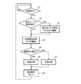
- FIG. 4 is a flowchart for explaining the transport control of the printing apparatus 1.
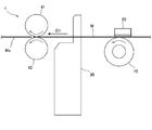
- FIG. 5 and 6 are side views for explaining the transport control of the printing apparatus 1.
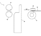
- FIG. 7 is a side view showing the internal structure of the printing apparatus 1 in a slack state of the medium M.
- FIG. 8 is a diagram showing the relationship between the transport speed and the time in the speed change printing (No. 1).
- FIG. 9 is a diagram showing the relationship between the transport speed and the time in the speed change printing (No. 2).
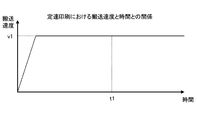
- FIG. 10 is a diagram showing the relationship between speed and time in constant speed printing.
- control unit 71 shown in FIG. 3 first prints the next print by the print head 20 based on the operation of the user in the printing device 1 or the information received from the computer that generates the print data. The determination of whether or not there is a start command is repeated until the start command is received (step S1).
- Step S2 After receiving the next printing start command (step S1: YES), the control unit 71 determines whether the medium M is sandwiched and held by the pair of ejection rollers 41 and 42, as shown in FIG. (Step S2). This determination process is determined by, for example, in the discharge operation process (step S8) described later, whether or not an operation of transporting the medium M to a position sandwiched by the pair of discharge rollers 41 and 42 is performed in the discharge direction D1. Can be done. However, the control unit 71 may determine whether or not the medium M is sandwiched and held by the pair of discharge rollers 41 and 42 based on the detection result of the sensor that detects the medium M.
- step S2 NO
- the platen roller 10 causes the medium M to be sandwiched by the pair of discharge rollers 41 and 42.
- the transport drive unit 60 is controlled so as to transport in the discharge direction D1 to the sandwiched position (step S3).
- the control unit 71 prints from the tip of the medium M (the upstream end in the reverse direction D2, that is, the downstream end in the discharge direction D1) at the time of the next printing.
- the transport drive unit 60 is controlled so that the platen roller 10 transports the medium M in the opposite direction D2 opposite to the discharge direction D1 until the tip of the medium M reaches between the platen roller 10 and the print head 20.
- the control unit 71 acquires print data when the medium M is conveyed in the reverse direction D2.
- the reverse transfer process may be performed immediately after the discharge operation (step S8). In that case, in the determination process of step S2 described above, the control unit 71 uses the pair of discharge rollers 41, It is preferable to determine whether the reverse transfer process is performed after the medium M is sandwiched and held by the 42.
- the control unit 71 determines whether or not the speed change setting for lowering the transport speed of the medium M is performed when an impact is applied to the medium M, as will be described later (step S5).
- This speed change setting is set, for example, based on the operation of the user in the printing device 1 or based on the information received from the computer that generates the print data.
- the speed change setting as shown in FIG. 6, the medium M is conveyed in the reverse direction D2, so that the slack portion (deflection portion) Mb generated in the medium M as shown in FIG. 7 is the medium at the time of printing.
- This is a setting for lowering the transport speed when an impact is applied to the medium M when it is eliminated by transporting M in the discharge direction D1.
- the slack portion Mb is eliminated.
- the impact is applied to the medium M in a state where the medium M is sandwiched between the pair of discharge rollers 41 and 42. Therefore, the medium M is impacted while being held between the pair of discharge rollers 41 and 42 and between the platen roller 10 and the print head 20. The impact increases as the outer diameter of the roll of the medium M becomes longer.
- the control unit 71 causes the print head 20 to perform variable speed printing while changing the transport speed of the medium M (step S6). For example, as shown in FIG. 8, the control unit 71 accelerates the transport speed to a high speed v1 after the start of transport of the medium M at the time of printing, and then accelerates the transport speed to a high speed v1 at a time t1 when an impact is applied to the medium M.
- the transport speed is reduced so as to be, and the transport drive unit 60 is controlled so as to accelerate the transport speed to the high speed v2 again after the time t1.
- the print head 20 prints on the medium M so as to correspond to the above-mentioned changing transport speed.
- the control unit 71 accelerates the speed change printing (step S6) to a low speed v2 after the start of transporting the medium M at the time of printing, and the time during which the medium M is impacted.
- the transport drive unit 60 may be controlled so as to accelerate the transport speed to a high speed v1.
- the high-speed speed v1 has a long transport time, the reduction in printing processing capacity due to the low-speed v2 can be suppressed to a minimum.
- step S5 When the speed change setting is not performed, or when the speed change setting function itself is not mounted on the printing device 1 (step S5: NO), the control unit 71 prints without changing the transport speed of the medium M.
- the head 20 is made to perform constant speed printing (step S7). For example, as shown in FIG. 10, the control unit 71 accelerates the transport speed to a high-speed speed v1 after the start of transport of the medium M at the time of printing, and the high-speed speed v1 even at the time t1 when the medium M is impacted.
- the transport drive unit 60 is controlled so as to transport the medium M as it is.
- the control unit 71 controls the ejection operation of the printed portion Ma after the speed change printing (step S6) or the constant speed printing (step S7) is performed (step S8).
- the medium M is transported in the discharge direction D1 by the platen roller 10 (convey drive unit 60) so that the rear end (upstream end) in the discharge direction D1 of the printed portion Ma reaches the cutter 30.
- the cutter 30 is controlled so as to cut out the printed portion Ma. Further, as shown in FIG.
- control unit 71 is a transport drive unit so that the platen roller 10 transports the medium M in the discharge direction D1 to a position where the medium M is sandwiched between the pair of discharge rollers 41 and 42 and makes the medium M stand by. It is good to control 60. Then, the control unit 71 repeats the process from step S1 described above.
- the printing apparatus 1 conveys the platen roller 10, which is an example of the conveying unit, the printing head 20, the cutter 30, and the pair of discharging rollers 41, 42, which is an example of the discharging unit.
- a drive unit 60 and a control unit 71 are provided.
- the platen roller 10 unwinds and conveys a long medium M wound in a roll shape.
- the print head 20 is arranged to face the platen roller 10 and prints on the medium M.
- the cutter 30 cuts out the printed portion Ma printed by the print head 20 from the medium M.
- the pair of discharge rollers 41 and 42 sandwich and convey the printed portion Ma cut out by the cutter 30.
- the transport drive unit 60 drives at least the platen roller 10.
- the control unit 71 controls the transport drive unit 60.
- the medium M is a pair of ejection rollers.
- the transport drive unit 60 is controlled so that the platen roller 10 transports the medium M in the discharge direction D1 to a position sandwiched by the 41 and 42 (step S8 or step S3).
- the medium M is conveyed by the platen roller 10 from the position sandwiched by the pair of ejection rollers 41 and 42 to the opposite direction D2 opposite to the ejection direction D1, and then printing is started. Therefore, the slack portion Mb generated in the medium M at the start of printing due to the transfer in the reverse direction D2 starts to be conveyed in the reverse direction D2 of the medium M when it is subsequently conveyed in the discharge direction D1 at the time of printing. It will be resolved at the position where it was printed. Then, at the position where the transfer to the reverse direction D2 is started, the medium M is held at two places, between the pair of discharge rollers 41 and 42, and between the platen roller 10 and the print head 20.
- the medium M can receive an impact due to the elimination of the slack portion Mb in the state of being held in this way. Therefore, since the slip caused by the impact on the medium M can be suppressed, it is possible to suppress the occurrence of printing defects such as printing (printing) shrinkage. As described above, according to the present embodiment, it is possible to suppress the occurrence of printing defects in the long medium M wound in a roll shape.
- the platen roller 10 conveys the medium M in the discharge direction D1 to a position sandwiched by the pair of discharge rollers 41 and 42. After receiving a command to start the next printing by the print head 20, the platen roller 10 transports the medium M in the direction D2 opposite to the discharge direction D1.
- the transport drive unit 60 is controlled.
- the platen roller 10 conveys the medium M in the opposite direction D2 so as to reach between the platen roller 10 and the printing head 20 in advance in order to start printing from the tip of the medium M.
- the tip of the medium M is held on the platen roller 10 for a long time so that it sticks to the platen roller 10 and the medium M can be caught in the platen roller 10 after the start of the printing operation.
- the control unit 71 reaches a position where the platen roller 10 sandwiches the medium M between the pair of discharge rollers 41 and 42 after the printed portion Ma is cut out by the cutter 30. It is conveyed in the discharge direction D1 and is made to stand by.
- the tip of the medium M is not held on the platen roller 10 for a long time, so that the tip of the medium M is stuck to the platen roller 10 to prevent the medium M from being caught in the platen roller 10 after the start of the printing operation. be able to.
- the platen roller 10 conveys the medium M in the discharge direction D1 to stand by, so that the cut out printed portion Ma is cut out by the platen roller 10.
- the discharge rollers 41, 42 driven by the same drive source as the above (or by the remaining medium M) can be pushed out to promote discharge.
- the control unit 71 conveys the medium M in the reverse direction D2 opposite to the discharge direction D1, so that the platen roller 10 moves in the reverse direction D2.
- control unit 71 is in a state where the medium M is conveyed by the platen roller 10 in the opposite direction D2 opposite to the discharge direction D1 from the position where the medium M is sandwiched by the pair of discharge rollers 41 and 42.
- the platen roller becomes low speed (speed v2) at the position where the transfer of the medium M in the reverse direction D2 is started, and becomes high speed (speed v1) at at least some other positions.
- the transport drive unit 60 is controlled so that the vehicle 10 transports the medium M in the discharge direction D1.
- the transfer speed of the medium M when receiving an impact is set to a low speed v2.
- the impact can be mitigated. Therefore, since the slip caused by the impact applied to the medium M can be further suppressed, it is possible to further suppress the occurrence of printing defects.
- the present invention is not limited to the above-described embodiment as it is, and the components can be modified and embodied.
- various inventions can be formed by an appropriate combination of a plurality of components disclosed in the present embodiment. In this way, various modifications and applications of the invention are possible within a range that does not deviate from the purpose of the invention.
- Printing device 10 Platen roller 20 Printing head 30 Cutter 41, 42 Discharge roller 50 Roll shaft part 60 Transport drive unit 71 Control unit 72 Storage unit 73 Interface unit D1 Discharge direction D2 Reverse direction M Medium Ma Printing part Mb Slack part
Landscapes
- Handling Of Sheets (AREA)
Abstract
印刷装置(1)において、搬送部の一例であるプラテンローラ(10)は、ロール状に巻かれた媒体(M)を巻き出して搬送する。印刷ヘッド(20)は、媒体(M)に印刷を行う。カッタ(30)は、媒体(M)から、印刷ヘッド(20)によって印刷が行われた印刷部分(Ma)を切り出す。排出部の一例である排出ローラ(41,42)は、カッタ(30)によって切り出された印刷部分(Ma)を挟み込んで搬送する。搬送駆動部(60)は、少なくともプラテンローラ(10)を駆動する。制御部(71)は、搬送駆動部(60)を制御する。制御部(71)は、カッタ(30)によって印刷部分(Ma)が切り出された後(S8)で、且つ印刷ヘッド(20)によって印刷が開始される前に(S6,S7)、媒体(M)が一対の排出ローラ(41,42)によって挟み込まれる位置までプラテンローラ(10)が媒体(M)を排出方向(D1)に搬送するように搬送駆動部(60)を制御する(S8,S3)。
Description
本発明は、媒体に印刷を行う印刷装置に関する。
従来、エアラインプリンタなどの印刷装置では、手荷物タグやレシートなどの媒体は、ロール状に巻かれた状態から巻き出されることで搬送され、印刷ヘッドによって印刷が行われる。また、媒体は、印刷が行われた印刷部分がカッタによって切り出され、この印刷部分が一対の排出ローラによって排出される。一方、印刷部分が切り出された残りの媒体は、次の印刷の前に、先端が印刷ヘッドによる印刷位置に戻るように排出方向とは反対の逆方向に搬送される。
このような印刷装置において、先端を印刷位置に戻すために逆方向への搬送を行うものではないが、ロール紙のカット面の変形に起因するジャムエラー等の不具合を防止するために、カット面を排出用搬送経路内で待機させる装置が提案されている(例えば、特許文献1参照)。
なお、印字装置に着脱自在に配置される給送装置において、媒体のたるみが検出されると給送速度を速める給送機構を備える給送装置が提案されている(例えば、特許文献2参照)。
ところで、印刷部分が切り出された後に媒体が排出方向とは反対の逆方向へ搬送されることによって、媒体にはたるみ部分が生じる。その後、媒体が排出方向に搬送されてたるみ部分が解消される際に、媒体に衝撃が加わる。印刷装置に用いられる媒体は、交換回数を減らすためには、ロール外径が長いものが用いられることが望ましいが、ロール外径が長いほど、媒体に加わる衝撃が強くなる。
上述のように媒体に加わる衝撃は、媒体に印刷(印字)縮みなどの印刷不良(印刷乱れ)を引き起こす。このような印刷不良は、衝撃によって媒体がスリップすることによるものと考えられる。
本発明の目的は、このような事情に鑑みてなされたものであり、ロール状に巻かれた媒体に印刷不良が発生するのを抑制することができる印刷装置を提供することである。
開示の印刷装置は、ロール状に巻かれた媒体を巻き出して搬送する搬送部と、前記媒体に印刷を行う印刷ヘッドと、前記媒体から、前記印刷ヘッドによって印刷が行われた印刷部分を切り出すカッタと、前記カッタによって切り出された前記印刷部分を挟み込んで搬送する排出部と、少なくとも前記搬送部を駆動する搬送駆動部と、前記搬送駆動部を制御する制御部と、を備え、前記制御部は、前記カッタによって前記印刷部分が切り出された後で、且つ前記印刷ヘッドによって印刷が開始される前に、前記媒体が前記排出部によって挟み込まれる位置まで前記搬送部が前記媒体を排出方向に搬送するように前記搬送駆動部を制御する。
開示の印刷装置によれば、ロール状に巻かれた媒体に印刷不良が発生するのを抑制することができる。
以下、本発明の一実施の形態に係る印刷装置について、図面を参照しながら説明する。
図1は、印刷装置1の内部構造を示す側面図である。
図1は、印刷装置1の内部構造を示す側面図である。
図2は、印刷装置1の一部の内部構造を示す側面図である。
図3は、印刷装置1の制御構成を示す図である。
図3は、印刷装置1の制御構成を示す図である。
図1に示すように、印刷装置1は、搬送部の一例であるプラテンローラ10と、印刷ヘッド20と、カッタ30と、排出部の一例である一対の排出ローラ41,42と、ロール軸部50と、を備える。また、図3に示すように、印刷装置1は、搬送駆動部60と、制御部71と、記憶部72と、インターフェース部73と、を更に備える。
プラテンローラ10は、後述する搬送駆動部60の駆動によって回転することで、長尺状の媒体Mを搬送する。プラテンローラ10は、例えばゴムローラである。なお、プラテンローラ10は、ロール状に巻かれた長尺状の媒体Mを巻き出して搬送する搬送部の一例であるが、この搬送部としては、プラテンローラ10以外の搬送ローラや搬送ベルトなどであってもよい。
媒体Mは、例えば外径が200mmのロール状に巻かれており、軸芯において例えば後述するロール軸部50によって回転可能に支持されている。また、媒体Mの一例としては、エアラインプリンタにおいて手荷物タグとして用いられ、一方の面(表面)又は内部に接着層を有するラベルが挙げられる。ロール状に巻かれた媒体Mは、後述する図5に示すようにプラテンローラ10の回転によって排出方向D1に巻き出されて搬送される。一方、図6に示すように、プラテンローラ10が逆回転すると、媒体Mは、排出方向D1とは反対の逆方向D2に搬送される。
印刷ヘッド20は、プラテンローラ10に対向して配置されている。また、印刷ヘッド20は、プラテンローラ10との間に挟み込まれた媒体Mに印刷(印字)を行う。印刷ヘッド20の印刷方式は、特に制限はないが、例えば、感熱方式である。なお、印刷ヘッド20の印刷方式が感熱方式である場合には、媒体Mは、例えば感熱ラベルである。
図2に示すように、カッタ30は、媒体Mから、印刷ヘッド20によって印刷が行われた印刷部分Maを切り出す。
一対の排出ローラ41,42は、互いに対向して配置され、カッタ30によって切り出された印刷部分Maを挟み込んで搬送する。一対の排出ローラ41,42のうちの一方の排出ローラ41は、後述する搬送駆動部60の駆動によって回転する駆動ローラであり、他方の排出ローラ42は、従動ローラである。なお、一対の排出ローラ41,42は、排出部の一例であるが、この排出部としては、排出ベルトなどが用いられてもよい。
図1に示すロール軸部50は、上述のように、ロール状に巻かれた媒体Mの軸芯において、媒体Mを回転可能に支持する。
図3に示す搬送駆動部60は、排出ローラ41及びプラテンローラ10を駆動する例えばモータである。そのため、一対の排出ローラ41,42及びプラテンローラ10は、互いに同一のタイミングで回転する。なお、駆動ローラである排出ローラ41を駆動する搬送駆動部と、プラテンローラ10を駆動する搬送駆動部とが個別に配置されていてもよい。
制御部71は、印刷ヘッド20、カッタ30が有するカッタ駆動部、搬送駆動部60などを制御する。例えば、制御部71は、記憶部72に記憶されているプログラムを読み出して実行するプロセッサ(例えばCPU:Central Processing Unit)を有する。
記憶部72は、例えば、制御部71のプロセッサによって実行されるプログラムを記憶する読み出し専用半導体メモリであるROM(Read Only Memory)、プロセッサが各種のプログラムを実行する際に必要に応じて作業用記憶領域として使用される随時書き込み読み出し可能な半導体メモリであるRAM(Random Access Memory)などである。
インターフェース部73は、外部機器との間で各種情報を授受する。例えば、インターフェース部73は、プロセッサによって実行されるプログラムを記憶媒体から或いはネットワークを介して取得したり、或いは、印刷データを生成するコンピュータから印刷データを受信したりする。
以下、印刷装置1の搬送制御について、図4~図10を参照しながら説明する。
図4は、印刷装置1の搬送制御を説明するためのフローチャートである。
図4は、印刷装置1の搬送制御を説明するためのフローチャートである。
図5及び図6は、印刷装置1の搬送制御を説明するための側面図である。
図7は、媒体Mがたるんだ状態の印刷装置1の内部構造を示す側面図である。
図7は、媒体Mがたるんだ状態の印刷装置1の内部構造を示す側面図である。
図8は、変速印刷(その1)における搬送速度と時間との関係を示す図である。
図9は、変速印刷(その2)における搬送速度と時間との関係を示す図である。
図10は、定速印刷における速度と時間との関係を示す図である。
図9は、変速印刷(その2)における搬送速度と時間との関係を示す図である。
図10は、定速印刷における速度と時間との関係を示す図である。
図3に示す制御部71は、まず、図4に示すように、印刷装置1におけるユーザの操作に基づき、或いは印刷データを生成するコンピュータから受信する情報に基づき、印刷ヘッド20による次の印刷の開始指令があったかの判定を、開始指令を受けるまで繰り返す(ステップS1)。
制御部71は、次の印刷の開始指令を受けた後(ステップS1:YES)、図5に示すように、一対の排出ローラ41,42によって媒体Mが挟み込まれて保持されているかを判定する(ステップS2)。この判定処理は、例えば、後述する排出動作処理(ステップS8)において、媒体Mを一対の排出ローラ41,42によって挟み込まれる位置まで排出方向D1に搬送する動作が行われたか否かによって判定することができる。但し、制御部71は、媒体Mを検知するセンサの検知結果に基づいて、一対の排出ローラ41,42によって媒体Mが挟み込まれて保持されているかを判定してもよい。
制御部71は、一対の排出ローラ41,42によって媒体Mが挟み込まれて保持されていないと判定した場合(ステップS2:NO)のみ、プラテンローラ10が媒体Mを一対の排出ローラ41,42によって挟み込まれる位置まで排出方向D1に搬送するように搬送駆動部60を制御する(ステップS3)。
その後、制御部71は、図6に示すように、次の印刷時に媒体Mの先端(逆方向D2における上流側端部、すなわち、排出方向D1における下流側端部)から印刷が行われるように、媒体Mの先端がプラテンローラ10と印刷ヘッド20との間に到達するまで、プラテンローラ10が媒体Mを排出方向D1とは反対の逆方向D2に搬送するように搬送駆動部60を制御する(ステップS4)。制御部71は、媒体Mが逆方向D2に搬送されているときに、印刷データを取得する。なお、逆搬送処理(ステップS4)は、排出動作(ステップS8)の直後に行われてもよいが、その場合、上述のステップS2の判定処理において、制御部71は、一対の排出ローラ41,42によって媒体Mが挟み込まれて保持されてから逆搬送処理が行われたかを判定するとよい。
次に、制御部71は、後述するように媒体Mに衝撃が加わる際に媒体Mの搬送速度を低速にする速度変化設定が行われているかを判定する(ステップS5)。この速度変化設定は、例えば、印刷装置1におけるユーザの操作に基づき、或いは印刷データを生成するコンピュータから受信する情報に基づき、設定される。なお、速度変化設定は、図6に示すように媒体Mが逆方向D2に搬送されることによって、図7に示すように媒体Mに生じたたるみ部分(たわみ部分)Mbが、印刷時の媒体Mの排出方向D1への搬送によって解消されるときに媒体Mに衝撃が加わる際に搬送速度を低速とするための設定である。上述のように、媒体Mは、図6に示す一対の排出ローラ41,42によって挟み込まれる位置まで排出方向D1に搬送されてから逆方向D2に搬送されているため、たるみ部分Mbが解消されて媒体Mに衝撃が加わるのは、媒体Mが一対の排出ローラ41,42によって挟み込まれた状態である。そのため、媒体Mは、一対の排出ローラ41,42の間、及びプラテンローラ10と印刷ヘッド20との間の2箇所で保持された状態で衝撃を受ける。なお、この衝撃は、媒体Mのロール外径が長いほど大きくなる。
制御部71は、速度変化設定が行われている場合(ステップS5:YES)、媒体Mの搬送速度を変化させながら印刷ヘッド20に変速印刷を行わせる(ステップS6)。例えば、制御部71は、図8に示すように、印刷時における媒体Mの搬送開始後、高速の速度v1まで搬送速度を加速させ、その後、媒体Mに衝撃が加わる時間t1において低速の速度v2となるように搬送速度を減速させ、時間t1よりも後に、再び高速の速度v2まで搬送速度を加速させるように搬送駆動部60を制御する。なお、印刷ヘッド20は、上述の変化する搬送速度に対応するように媒体Mに印刷を行う。
或いは、制御部71は、変速印刷(ステップS6)を、図9に示すように、印刷時における媒体Mの搬送開始後、低速の速度v2まで搬送速度を加速させ、媒体Mに衝撃が加わる時間t1よりも後に、高速の速度v1まで搬送速度を加速させるように搬送駆動部60を制御してもよい。但し、図8に示すように、高速の速度v1の搬送時間が長い方が、搬送速度を低速v2とすることに起因する印刷処理能力低減を最小限に抑制することができる。
制御部71は、速度変化設定が行われていない場合、或いは速度変化設定の機能自体が印刷装置1に搭載されていない場合(ステップS5:NO)、媒体Mの搬送速度を変化させずに印刷ヘッド20に定速印刷を行わせる(ステップS7)。例えば、制御部71は、図10に示すように、印刷時における媒体Mの搬送開始後、高速の速度v1まで搬送速度を加速させ、媒体Mに衝撃が加わる時間t1においても高速の速度v1のまま媒体Mを搬送するように搬送駆動部60を制御する。
制御部71は、変速印刷(ステップS6)又は定速印刷(ステップS7)が行われた後、印刷部分Maの排出動作の制御を行う(ステップS8)。例えば、制御部71は、印刷部分Maの排出方向D1における後端(上流側端部)がカッタ30まで到達するようにプラテンローラ10(搬送駆動部60)によって媒体Mが排出方向D1に搬送された後(図2参照)、印刷部分Maを切り出すようにカッタ30を制御する。また、制御部71は、図5に示すように、媒体Mが一対の排出ローラ41,42によって挟み込まれる位置までプラテンローラ10が媒体Mを排出方向D1に搬送して待機させるように搬送駆動部60を制御するとよい。そして、制御部71は、上述のステップS1から処理を繰り返す。
以上説明した本実施の形態では、印刷装置1は、搬送部の一例であるプラテンローラ10と、印刷ヘッド20と、カッタ30と、排出部の一例である一対の排出ローラ41,42と、搬送駆動部60と、制御部71と、を備える。プラテンローラ10は、ロール状に巻かれた長尺状の媒体Mを巻き出して搬送する。印刷ヘッド20は、プラテンローラ10に対向して配置され、媒体Mに印刷を行う。カッタ30は、媒体Mから、印刷ヘッド20によって印刷が行われた印刷部分Maを切り出す。一対の排出ローラ41,42は、カッタ30によって切り出された印刷部分Maを挟み込んで搬送する。搬送駆動部60は、少なくともプラテンローラ10を駆動する。制御部71は、搬送駆動部60を制御する。また、制御部71は、カッタ30によって印刷部分Maが切り出された後で(ステップS8)、且つ印刷ヘッド20によって印刷が開始される前に(ステップS6,S7)、媒体Mが一対の排出ローラ41,42によって挟み込まれる位置までプラテンローラ10が媒体Mを排出方向D1に搬送するように搬送駆動部60を制御する(ステップS8又はステップS3)。
これにより、その後、媒体Mが一対の排出ローラ41,42によって挟み込まれる位置からプラテンローラ10によって排出方向D1とは反対の逆方向D2に搬送されてから印刷が開始される。そのため、逆方向D2への搬送に起因して印刷開始時に媒体Mに生じているたるみ部分Mbは、その後、印刷時に排出方向D1に搬送される際に媒体Mの逆方向D2への搬送が開始された位置において解消される。そして、この逆方向D2への搬送が開始された位置において、媒体Mは、一対の排出ローラ41,42の間、及びプラテンローラ10と印刷ヘッド20との間の2箇所で保持される。そのため、媒体Mは、このように保持された状態で、たるみ部分Mbが解消されることに起因する衝撃を受けることができる。したがって、媒体Mに衝撃が加わることに伴い生じるスリップを抑制することができるため、印刷(印字)縮み等の印刷不良が発生するのを抑制することができる。以上のとおり、本実施の形態によれば、ロール状に巻かれた長尺状の媒体Mに印刷不良が発生するのを抑制することができる。
また、本実施の形態では、制御部71は、カッタ30によって印刷部分Maが切り出された後、一対の排出ローラ41,42によって挟み込まれる位置までプラテンローラ10が媒体Mを排出方向D1に搬送して待機させるように搬送駆動部60を制御し、印刷ヘッド20による次の印刷の開始指令を受けた後、プラテンローラ10が媒体Mを排出方向D1とは反対の逆方向D2に搬送するように搬送駆動部60を制御する。
ところで、印刷部分Maの切り出し後に、媒体Mの先端から印刷を開始するために予めプラテンローラ10と印刷ヘッド20との間に到達するようにプラテンローラ10が媒体Mの逆方向D2への搬送を行う態様では、媒体Mの先端が、プラテンローラ10上に長時間保持されることによって、プラテンローラ10に貼り付き、印刷動作の開始後に媒体Mがプラテンローラ10に巻き込まれ得る。それに対し、本実施の形態では、上述のように、制御部71は、カッタ30によって印刷部分Maが切り出された後、プラテンローラ10が媒体Mを一対の排出ローラ41,42によって挟み込まれる位置まで排出方向D1に搬送して待機させる。これにより、媒体Mの先端がプラテンローラ10上に長時間保持されないため、媒体Mの先端がプラテンローラ10に貼り付くことで印刷動作の開始後に媒体Mがプラテンローラ10に巻き込まれるのを防止することができる。
更には、本実施の形態では、カッタ30によって印刷部分Maが切り出された後、プラテンローラ10が媒体Mを排出方向D1に搬送して待機させるため、切り出された印刷部分Maを、プラテンローラ10と同一駆動源で駆動する排出ローラ41,42によって(或いは残りの媒体Mによって)、押し出して排出を促すことができる。
したがって、媒体Mがプラテンローラ10に巻き込まれるのを防止することができるとともに印刷部分Ma(媒体M)の排出を促すことができる。更には、制御部71は、印刷ヘッド20による次の印刷の開始指令を受けた後、プラテンローラ10が媒体Mを排出方向D1とは反対の逆方向D2に搬送するため、逆方向D2への搬送と印刷データの受信とを並行処理することで、印刷処理能力低減を抑えることもできる。
また、本実施の形態では、制御部71は、媒体Mが一対の排出ローラ41,42によって挟み込まれる位置からプラテンローラ10によって媒体Mが排出方向D1とは反対の逆方向D2に搬送された状態で印刷が開始された後、媒体Mの逆方向D2への搬送が開始された位置において低速(速度v2)となり、他の少なくとも一部の位置において高速(速度v1)となる搬送速度でプラテンローラ10が媒体Mを排出方向D1に搬送するように搬送駆動部60を制御する。
これにより、たるみ部分Mbが解消される位置である、媒体Mの逆方向D2への搬送が開始された位置において、衝撃を受ける際の媒体Mの搬送速度を低速の速度v2とすることで、衝撃を緩和することができる。したがって、媒体Mに衝撃が加わることに伴い生じるスリップを更に抑制することができるため、印刷不良が発生するのを更に抑制することができる。
なお、本発明は、上述の実施の形態そのままに限定されず、構成要素を変形して具体化することができる。例えば、本実施の形態に開示されている複数の構成要素の適宜な組み合わせにより、種々の発明を形成することができる。このように、発明の趣旨を逸脱しない範囲内において発明の種々の変形や応用が可能である。
1 印刷装置
10 プラテンローラ
20 印刷ヘッド
30 カッタ
41,42 排出ローラ
50 ロール軸部
60 搬送駆動部
71 制御部
72 記憶部
73 インターフェース部
D1 排出方向
D2 逆方向
M 媒体
Ma 印刷部分
Mb たるみ部分
10 プラテンローラ
20 印刷ヘッド
30 カッタ
41,42 排出ローラ
50 ロール軸部
60 搬送駆動部
71 制御部
72 記憶部
73 インターフェース部
D1 排出方向
D2 逆方向
M 媒体
Ma 印刷部分
Mb たるみ部分
Claims (3)
- ロール状に巻かれた媒体を巻き出して搬送する搬送部と、
前記媒体に印刷を行う印刷ヘッドと、
前記媒体から、前記印刷ヘッドによって印刷が行われた印刷部分を切り出すカッタと、
前記カッタによって切り出された前記印刷部分を挟み込んで搬送する排出部と、
少なくとも前記搬送部を駆動する搬送駆動部と、
前記搬送駆動部を制御する制御部と、を備え、
前記制御部は、前記カッタによって前記印刷部分が切り出された後で、且つ前記印刷ヘッドによって印刷が開始される前に、前記媒体が前記排出部によって挟み込まれる位置まで前記搬送部が前記媒体を排出方向に搬送するように前記搬送駆動部を制御する、
ことを特徴とする印刷装置。 - 前記制御部は、前記カッタによって前記印刷部分が切り出された後、前記排出部によって挟み込まれる位置まで前記搬送部が前記媒体を前記排出方向に搬送して待機させるように前記搬送駆動部を制御し、前記印刷ヘッドによる次の印刷の開始指令を受けた後、前記搬送部が前記媒体を前記排出方向とは反対の逆方向に搬送するように前記搬送駆動部を制御する、
ことを特徴とする請求項1記載の印刷装置。 - 前記制御部は、前記媒体が前記排出部によって挟み込まれる位置から前記搬送部によって前記媒体が前記排出方向とは反対の逆方向に搬送された状態で印刷が開始された後、前記媒体の前記逆方向への搬送が開始された位置において低速となり、他の少なくとも一部の位置において高速となる搬送速度で前記搬送部が前記媒体を前記排出方向に搬送するように前記搬送駆動部を制御する、
ことを特徴とする請求項1又は2記載の印刷装置。
Priority Applications (4)
| Application Number | Priority Date | Filing Date | Title |
|---|---|---|---|
| CN201980099988.2A CN114375260B (zh) | 2019-09-27 | 2019-09-27 | 打印装置 |
| PCT/JP2019/038149 WO2021059482A1 (ja) | 2019-09-27 | 2019-09-27 | 印刷装置 |
| JP2021548117A JP7196326B2 (ja) | 2019-09-27 | 2019-09-27 | 印刷装置 |
| US17/649,628 US11833812B2 (en) | 2019-09-27 | 2022-02-01 | Printing apparatus |
Applications Claiming Priority (1)
| Application Number | Priority Date | Filing Date | Title |
|---|---|---|---|
| PCT/JP2019/038149 WO2021059482A1 (ja) | 2019-09-27 | 2019-09-27 | 印刷装置 |
Related Child Applications (1)
| Application Number | Title | Priority Date | Filing Date |
|---|---|---|---|
| US17/649,628 Continuation US11833812B2 (en) | 2019-09-27 | 2022-02-01 | Printing apparatus |
Publications (1)
| Publication Number | Publication Date |
|---|---|
| WO2021059482A1 true WO2021059482A1 (ja) | 2021-04-01 |
Family
ID=75165975
Family Applications (1)
| Application Number | Title | Priority Date | Filing Date |
|---|---|---|---|
| PCT/JP2019/038149 Ceased WO2021059482A1 (ja) | 2019-09-27 | 2019-09-27 | 印刷装置 |
Country Status (4)
| Country | Link |
|---|---|
| US (1) | US11833812B2 (ja) |
| JP (1) | JP7196326B2 (ja) |
| CN (1) | CN114375260B (ja) |
| WO (1) | WO2021059482A1 (ja) |
Citations (3)
| Publication number | Priority date | Publication date | Assignee | Title |
|---|---|---|---|---|
| JPH03224764A (ja) * | 1990-09-19 | 1991-10-03 | Mutoh Ind Ltd | 連続記録紙の記録装置 |
| JP2010201820A (ja) * | 2009-03-04 | 2010-09-16 | Canon Inc | 搬送装置及び記録装置 |
| JP2017024221A (ja) * | 2015-07-17 | 2017-02-02 | 株式会社イシダ | ラベル発行装置 |
Family Cites Families (8)
| Publication number | Priority date | Publication date | Assignee | Title |
|---|---|---|---|---|
| DE60024191T2 (de) * | 1999-09-29 | 2006-07-20 | Seiko Epson Corp. | Druckgerät, Verfahren zu seiner Kontrolle und ein Datenspeichermedium zum Speichern eines das Verfahren ausführenden Computerprogrammes |
| JP2003118898A (ja) | 2001-10-16 | 2003-04-23 | Canon Ntc Inc | 印字装置の給送装置 |
| JP4251014B2 (ja) * | 2003-05-22 | 2009-04-08 | セイコーエプソン株式会社 | プリンタ及びプリンタの制御方法 |
| JP2008049670A (ja) * | 2006-08-28 | 2008-03-06 | Sato Corp | ラベルプリンタ |
| JP2008155417A (ja) * | 2006-12-21 | 2008-07-10 | Toshiba Tec Corp | プリンタ |
| JP2009131997A (ja) | 2007-11-29 | 2009-06-18 | Olympus Corp | 画像記録装置及び連続媒体の待機方法 |
| JP2017222492A (ja) * | 2016-06-17 | 2017-12-21 | 東芝テック株式会社 | 排紙装置および排紙方法 |
| JP6782584B2 (ja) * | 2016-08-30 | 2020-11-11 | 理想科学工業株式会社 | 印刷装置 |
-
2019
- 2019-09-27 CN CN201980099988.2A patent/CN114375260B/zh active Active
- 2019-09-27 JP JP2021548117A patent/JP7196326B2/ja active Active
- 2019-09-27 WO PCT/JP2019/038149 patent/WO2021059482A1/ja not_active Ceased
-
2022
- 2022-02-01 US US17/649,628 patent/US11833812B2/en active Active
Patent Citations (3)
| Publication number | Priority date | Publication date | Assignee | Title |
|---|---|---|---|---|
| JPH03224764A (ja) * | 1990-09-19 | 1991-10-03 | Mutoh Ind Ltd | 連続記録紙の記録装置 |
| JP2010201820A (ja) * | 2009-03-04 | 2010-09-16 | Canon Inc | 搬送装置及び記録装置 |
| JP2017024221A (ja) * | 2015-07-17 | 2017-02-02 | 株式会社イシダ | ラベル発行装置 |
Also Published As
| Publication number | Publication date |
|---|---|
| CN114375260B (zh) | 2023-09-15 |
| US11833812B2 (en) | 2023-12-05 |
| JPWO2021059482A1 (ja) | 2021-04-01 |
| CN114375260A (zh) | 2022-04-19 |
| JP7196326B2 (ja) | 2022-12-26 |
| US20220153042A1 (en) | 2022-05-19 |
Similar Documents
| Publication | Publication Date | Title |
|---|---|---|
| JP5617466B2 (ja) | 記録装置および記録・カット制御方法 | |
| JP7475165B2 (ja) | 記録装置、制御方法、およびプログラム | |
| JP2012000840A (ja) | 印刷装置 | |
| JP2022102562A (ja) | 記録装置、記録方法、記憶媒体及びプログラム | |
| JP3134871B1 (ja) | 昇華型カラープリンタ装置 | |
| CN107199788A (zh) | 记录装置以及记录装置的介质输送方法 | |
| JP5672122B2 (ja) | 画像形成装置及びプログラム | |
| JP7196325B2 (ja) | 印刷装置 | |
| WO2021059482A1 (ja) | 印刷装置 | |
| JP2002254740A (ja) | 画像形成装置の記録媒体搬送における汚染防止方法、および画像形成装置 | |
| JPH09142708A (ja) | 用紙排出装置 | |
| CN112208222B (zh) | 印刷装置及印刷方法 | |
| JP3731809B2 (ja) | 給紙装置およびプリンタ | |
| JP7228127B2 (ja) | プリンタ装置およびその制御方法 | |
| JP3326886B2 (ja) | プリンタ | |
| JPH044168A (ja) | 記録装置 | |
| JP2006007701A (ja) | 画像形成装置 | |
| JP2007161376A (ja) | シート給送装置及び記録装置 | |
| JP6618285B2 (ja) | シート搬送装置および処理装置 | |
| JP6408782B2 (ja) | 記録装置及び記録方法 | |
| JP5339155B2 (ja) | プリンタおよび搬送装置 | |
| JP3220722B2 (ja) | シリアルプリンタ | |
| JPH08300696A (ja) | 熱転写型記録装置 | |
| JP2022127765A (ja) | 印刷装置 | |
| JP2006272610A (ja) | 印刷装置 |
Legal Events
| Date | Code | Title | Description |
|---|---|---|---|
| 121 | Ep: the epo has been informed by wipo that ep was designated in this application |
Ref document number: 19947366 Country of ref document: EP Kind code of ref document: A1 |
|
| ENP | Entry into the national phase |
Ref document number: 2021548117 Country of ref document: JP Kind code of ref document: A |
|
| NENP | Non-entry into the national phase |
Ref country code: DE |
|
| 122 | Ep: pct application non-entry in european phase |
Ref document number: 19947366 Country of ref document: EP Kind code of ref document: A1 |