WO2021054089A1 - 画像処理装置、画像処理方法およびプログラム - Google Patents
画像処理装置、画像処理方法およびプログラム Download PDFInfo
- Publication number
- WO2021054089A1 WO2021054089A1 PCT/JP2020/032732 JP2020032732W WO2021054089A1 WO 2021054089 A1 WO2021054089 A1 WO 2021054089A1 JP 2020032732 W JP2020032732 W JP 2020032732W WO 2021054089 A1 WO2021054089 A1 WO 2021054089A1
- Authority
- WO
- WIPO (PCT)
- Prior art keywords
- pixel
- image
- image processing
- unit
- value
- Prior art date
Links
- 238000012545 processing Methods 0.000 title claims abstract description 276
- 238000003672 processing method Methods 0.000 title claims description 18
- 238000004364 calculation method Methods 0.000 claims abstract description 52
- 238000000034 method Methods 0.000 claims description 40
- 210000002241 neurite Anatomy 0.000 claims description 26
- 238000009499 grossing Methods 0.000 claims description 14
- 210000004204 blood vessel Anatomy 0.000 claims description 7
- 238000010586 diagram Methods 0.000 description 31
- 238000003384 imaging method Methods 0.000 description 28
- 238000012986 modification Methods 0.000 description 25
- 230000004048 modification Effects 0.000 description 25
- 210000004027 cell Anatomy 0.000 description 24
- 238000001514 detection method Methods 0.000 description 20
- 230000010365 information processing Effects 0.000 description 18
- 238000004891 communication Methods 0.000 description 16
- 238000003860 storage Methods 0.000 description 14
- 230000006870 function Effects 0.000 description 8
- 210000005056 cell body Anatomy 0.000 description 5
- 238000010191 image analysis Methods 0.000 description 4
- 210000002569 neuron Anatomy 0.000 description 4
- 238000004458 analytical method Methods 0.000 description 3
- 230000000694 effects Effects 0.000 description 3
- 108090000623 proteins and genes Proteins 0.000 description 3
- 108010043121 Green Fluorescent Proteins Proteins 0.000 description 2
- 102000004144 Green Fluorescent Proteins Human genes 0.000 description 2
- 238000012258 culturing Methods 0.000 description 2
- 238000011156 evaluation Methods 0.000 description 2
- 238000002073 fluorescence micrograph Methods 0.000 description 2
- 108091006047 fluorescent proteins Proteins 0.000 description 2
- 102000034287 fluorescent proteins Human genes 0.000 description 2
- 239000005090 green fluorescent protein Substances 0.000 description 2
- 230000003287 optical effect Effects 0.000 description 2
- 102000004169 proteins and genes Human genes 0.000 description 2
- 238000004113 cell culture Methods 0.000 description 1
- 238000004590 computer program Methods 0.000 description 1
- 238000012937 correction Methods 0.000 description 1
- 210000004748 cultured cell Anatomy 0.000 description 1
- 239000007850 fluorescent dye Substances 0.000 description 1
- 239000012634 fragment Substances 0.000 description 1
- 230000012447 hatching Effects 0.000 description 1
- 238000012744 immunostaining Methods 0.000 description 1
- 238000002372 labelling Methods 0.000 description 1
- 239000004973 liquid crystal related substance Substances 0.000 description 1
- 230000000877 morphologic effect Effects 0.000 description 1
- 230000002093 peripheral effect Effects 0.000 description 1
- 210000001525 retina Anatomy 0.000 description 1
- 238000012546 transfer Methods 0.000 description 1
Images


Classifications
-
- G06T5/70—
-
- G—PHYSICS
- G06—COMPUTING; CALCULATING OR COUNTING
- G06T—IMAGE DATA PROCESSING OR GENERATION, IN GENERAL
- G06T3/00—Geometric image transformation in the plane of the image
- G06T3/60—Rotation of a whole image or part thereof
-
- G—PHYSICS
- G06—COMPUTING; CALCULATING OR COUNTING
- G06T—IMAGE DATA PROCESSING OR GENERATION, IN GENERAL
- G06T5/00—Image enhancement or restoration
- G06T5/50—Image enhancement or restoration by the use of more than one image, e.g. averaging, subtraction
-
- G06T5/73—
-
- G—PHYSICS
- G06—COMPUTING; CALCULATING OR COUNTING
- G06T—IMAGE DATA PROCESSING OR GENERATION, IN GENERAL
- G06T7/00—Image analysis
- G06T7/10—Segmentation; Edge detection
- G06T7/11—Region-based segmentation
-
- G—PHYSICS
- G06—COMPUTING; CALCULATING OR COUNTING
- G06T—IMAGE DATA PROCESSING OR GENERATION, IN GENERAL
- G06T7/00—Image analysis
- G06T7/10—Segmentation; Edge detection
- G06T7/136—Segmentation; Edge detection involving thresholding
-
- C—CHEMISTRY; METALLURGY
- C12—BIOCHEMISTRY; BEER; SPIRITS; WINE; VINEGAR; MICROBIOLOGY; ENZYMOLOGY; MUTATION OR GENETIC ENGINEERING
- C12M—APPARATUS FOR ENZYMOLOGY OR MICROBIOLOGY; APPARATUS FOR CULTURING MICROORGANISMS FOR PRODUCING BIOMASS, FOR GROWING CELLS OR FOR OBTAINING FERMENTATION OR METABOLIC PRODUCTS, i.e. BIOREACTORS OR FERMENTERS
- C12M41/00—Means for regulation, monitoring, measurement or control, e.g. flow regulation
- C12M41/30—Means for regulation, monitoring, measurement or control, e.g. flow regulation of concentration
- C12M41/36—Means for regulation, monitoring, measurement or control, e.g. flow regulation of concentration of biomass, e.g. colony counters or by turbidity measurements
-
- G—PHYSICS
- G06—COMPUTING; CALCULATING OR COUNTING
- G06T—IMAGE DATA PROCESSING OR GENERATION, IN GENERAL
- G06T2207/00—Indexing scheme for image analysis or image enhancement
- G06T2207/20—Special algorithmic details
- G06T2207/20092—Interactive image processing based on input by user
- G06T2207/20104—Interactive definition of region of interest [ROI]
-
- G—PHYSICS
- G06—COMPUTING; CALCULATING OR COUNTING
- G06T—IMAGE DATA PROCESSING OR GENERATION, IN GENERAL
- G06T2207/00—Indexing scheme for image analysis or image enhancement
- G06T2207/20—Special algorithmic details
- G06T2207/20212—Image combination
- G06T2207/20221—Image fusion; Image merging
-
- G—PHYSICS
- G06—COMPUTING; CALCULATING OR COUNTING
- G06T—IMAGE DATA PROCESSING OR GENERATION, IN GENERAL
- G06T2207/00—Indexing scheme for image analysis or image enhancement
- G06T2207/30—Subject of image; Context of image processing
- G06T2207/30004—Biomedical image processing
- G06T2207/30024—Cell structures in vitro; Tissue sections in vitro
-
- G—PHYSICS
- G06—COMPUTING; CALCULATING OR COUNTING
- G06T—IMAGE DATA PROCESSING OR GENERATION, IN GENERAL
- G06T2207/00—Indexing scheme for image analysis or image enhancement
- G06T2207/30—Subject of image; Context of image processing
- G06T2207/30004—Biomedical image processing
- G06T2207/30101—Blood vessel; Artery; Vein; Vascular
-
- H—ELECTRICITY
- H04—ELECTRIC COMMUNICATION TECHNIQUE
- H04N—PICTORIAL COMMUNICATION, e.g. TELEVISION
- H04N1/00—Scanning, transmission or reproduction of documents or the like, e.g. facsimile transmission; Details thereof
- H04N1/40—Picture signal circuits
- H04N1/409—Edge or detail enhancement; Noise or error suppression
Definitions
- the present invention relates to an image processing apparatus, an image processing method and a program.
- the image processing apparatus is located at a position corresponding to the first pixel of the first image in the second image obtained by image processing the first image.
- a first image processing unit for setting the pixel value of the second pixel is provided, and the first image processing unit is a plurality of first pixel groups set corresponding to the first pixel, and the first image.
- the size of the pixel value of the first pixel group setting unit that sets a plurality of first pixel groups arranged along a predetermined direction in each of the images and the pixels included in each of the plurality of first pixel groups.
- a first calculation unit that calculates a plurality of first candidate pixel values based on the above, and a first pixel value that sets a pixel value of the second pixel of the second image based on the plurality of first candidate pixel values. It has a setting unit.
- the image processing method is a position of the second image obtained by image processing the first image, which is located at a position corresponding to the first pixel of the first image.
- the setting of the pixel value of the second pixel includes setting the pixel value of the second pixel, and the setting of the pixel value of the second pixel is a plurality of first pixel groups set corresponding to the first pixel, and is in the first image.
- a predetermined direction in each of a plurality of images obtained by arranging the first images at a plurality of different angles with respect to a predetermined direction or moving the first image at a plurality of different angles.
- a plurality of first candidate pixel values are calculated based on the setting of a plurality of first pixel groups arranged along the above and the size of the pixel values of the pixels included in each of the plurality of first pixel groups.
- the program is a second image of the second image at a position corresponding to the first pixel of the first image in the second image obtained by image processing the first image.
- a program for causing a processing device to perform a first image process for setting a pixel value of a pixel, the first image process is a plurality of first pixel groups set corresponding to the first pixel.
- the first image is arranged along a plurality of directions forming a plurality of different angles with respect to a predetermined direction in the first image, or a plurality of obtained by moving the first image at a plurality of different angles.
- the first pixel group setting process for setting a plurality of first pixel groups arranged along a predetermined direction in each of the images, and the size of the pixel values of the pixels included in each of the plurality of first pixel groups.
- First calculation process for calculating a plurality of first candidate pixel values based on the above, and first pixel setting process for setting the pixel value of the second pixel of the second image based on the plurality of first candidate pixel values. And.
- FIG. 1 is a conceptual diagram showing the configuration of the image processing apparatus of the first embodiment.
- FIG. 2 is a conceptual diagram showing a configuration of a data processing unit according to the first embodiment.
- FIG. 3 is a conceptual diagram showing a captured image according to the first embodiment.
- FIG. 4 is a conceptual diagram for explaining the first image processing according to the first embodiment.
- FIG. 5 is a conceptual diagram for explaining the second image processing according to the first embodiment.
- FIG. 6 is a flowchart showing the flow of the image processing method according to the first embodiment.
- FIG. 7 is a flowchart showing the flow of the first image processing according to the first embodiment.
- FIG. 8 is a flowchart showing the flow of the second image processing according to the first embodiment.
- FIG. 1 is a conceptual diagram showing the configuration of the image processing apparatus of the first embodiment.
- FIG. 2 is a conceptual diagram showing a configuration of a data processing unit according to the first embodiment.
- FIG. 3 is a conceptual diagram showing a captured image according to the
- FIG. 9 is a conceptual diagram showing the configuration of the data processing unit according to the second modification.
- FIG. 10 is a conceptual diagram for explaining the first image processing according to the second modification.
- FIG. 11 is a conceptual diagram showing the linear portion of the captured image and the position of the one-dimensional filter when the angles of the one-dimensional filter are 0 °, 30 °, 60 °, 90 °, 120 ° and 150 °. is there.
- FIG. 12 is a graph showing the angle of the one-dimensional filter and the average value of the pixel values of the plurality of pixels corresponding to the filter.
- FIG. 13 is a graph showing the angle of the one-dimensional filter and the average value of the pixel values of the plurality of pixels corresponding to the filter.
- FIG. 14 is a flowchart showing the flow of the image processing method according to the second modification.
- FIG. 15 is a conceptual diagram for explaining the setting of the range in which the first pixel is selected.
- FIG. 16 is a conceptual diagram showing an example of a display screen for displaying a highlighted image.
- FIG. 17 is a conceptual diagram showing an example of a display screen for setting parameters.
- FIG. 18 is a flowchart showing the flow of the image processing method according to the modified example 7.
- FIG. 19 is a conceptual diagram showing an example of a display screen according to the modified example 7.
- FIG. 20 is a conceptual diagram showing an example of a display screen according to the modified example 7.
- FIG. 21 is a conceptual diagram showing an example of a display screen according to the modified example 7.
- FIG. 22 is a conceptual diagram showing an example of a display screen according to the modified example 8.
- FIG. 23 is a conceptual diagram for explaining the provision of the program.
- FIG. 1 is a conceptual diagram showing the configuration of the image processing apparatus of the present embodiment.
- the image processing device 1 includes a culture unit 100 and an information processing unit 40.
- the culture unit 100 includes a culture chamber (culture chamber) 10, an observation sample table (stage) 11, a drive unit 12, and an imaging unit 20.
- the information processing unit 40 includes an input unit 41, a communication unit 42, a storage unit 43, an output unit 44, and a control unit 50.
- the control unit 50 includes a data processing unit 51, an output control unit 52, and a device control unit 53.
- the image processing device 1 is configured as a culture device, and is configured such that captured image data, which is image data obtained by imaging a sample (eg, a cell) in the culture unit 100, is input to the data processing unit 51 and processed. ing.
- image processing is performed from the captured image corresponding to the captured image data to emphasize a linear portion including straight lines, curves, polygonal lines, intersections, and the like.
- “emphasizing” means making it easier to distinguish the linear part from other parts (eg, the background part, the part other than the linear part) by the pixel value, and the brightness of the linear part is increased.
- the cell Ce is a nerve cell, and an example of emphasizing the portion corresponding to the neurite Nr as a linear portion will be described.
- the linear portion as described above is included, the object to be emphasized is Not limited to this example, it can be any element (eg, other cells, other than cells) that constitutes an image.
- the image processing may be performed on an image other than the captured image, such as a drawn image.
- the culture unit 100 includes a culture chamber 10 for culturing the cells Ce, and the imaging unit 20 takes an image of the cells Ce cultured in the culture chamber 10.
- the culture chamber 10 stores the culture container C in which the cells Ce are cultured.
- the culture vessel C is, for example, a well plate or a dish.
- a temperature controller eg, heater
- a temperature sensor not shown
- the inside of the culture chamber 10 is controlled so that the cells Ce are cultured in a preset environment, such as being maintained at a preset temperature by the temperature controller and the temperature sensor.
- the drive unit 12 includes an actuator, moves the culture vessel C at a predetermined time, and places it on the observation sample table 11 inside the culture chamber 10.
- the driving unit 12 places the imaging unit 20 or the observation sample table 11 or the like at an appropriate position in the optical axis direction (eg, so that the cell Ce is arranged on the focal plane of the imaging unit 20 for imaging the cell Ce). , Observation position).
- the image pickup unit 20 includes an image pickup device including an image pickup element such as CMOS or CCD, and images a cell Ce, particularly a neurite Nr of the cell Ce.
- an image pickup element such as CMOS or CCD
- the pixel corresponding to the neurite Nr is distinguished from other parts with desired accuracy by the brightness value of the pixel or a plurality of pixels around the pixel. If it can be done, it is not particularly limited.
- a fluorescence observation method, a phase difference observation method, or the like can be used as a method of imaging by the imaging unit 20 .
- the imaging unit 20 acquires a fluorescence image of the sample, and the fluorescence image is used for image analysis described later.
- the phase difference observation method the imaging unit 20 acquires the phase difference image of the sample.
- the phase difference image is used for image analysis described later.
- a fluorescent protein such as green fluorescent protein (GFP) is expressed in the cell Ce by gene transfer, or a protein localized in the neuroprojection Nr is fused with the fluorescent protein. Fluorescent staining can be performed by expressing the protein. If there is no problem in using cell Ce after imaging (eg, culture, passage, pickup), other labeling methods such as immunostaining may be performed.
- GFP green fluorescent protein
- the pixel signal obtained by imaging the cell Ce by the imaging unit 20 is converted into a digital signal and input to the information processing unit 40 as captured image data in which the pixels and the brightness value are associated with each other (arrow A1 in FIG. 1). ), Stored in the storage unit 43.
- the information processing unit 40 serves as an interface with a user of the image processing device 1 (hereinafter, simply referred to as a “user”), and also performs processing such as communication, storage, and calculation related to various data.
- the information processing unit 40 may be configured as an information processing device physically separated from the culture unit 100. Further, at least a part of the data used by the image processing device 1 may be stored in a remote server or the like connected by a network.
- the input unit 41 includes an input device such as a mouse, a keyboard, various buttons, and a touch panel.
- the input unit 41 receives from the user data and the like necessary for imaging by the culture unit 100 and data processing by the data processing unit 51.
- the communication unit 42 is provided with a communication device capable of communicating by wireless or wired connection such as the Internet, and appropriately transmits and receives data related to control and processing in the image processing device 1.
- the storage unit 43 includes a non-volatile storage medium, and stores a program for causing the control unit 50 to perform processing, image data related to the processing of the data processing unit 51, and the like.
- the output unit 44 includes a display device such as a liquid crystal monitor, and outputs an image or the like showing the information obtained by the processing of the data processing unit 51.
- the control unit 50 is composed of a processing device such as a CPU, functions as a main body of an operation for controlling the image processing device 1, and performs various processes by executing a program mounted on the storage unit 43.
- the data processing unit 51 of the control unit 50 acquires and processes the captured image data input from the imaging unit 20 to generate an image in which the linear portion of the captured image is emphasized.
- this image is referred to as an emphasized image.
- FIG. 2 is a conceptual diagram showing the configuration of the data processing unit 51.
- the data processing unit 51 includes a first image processing unit 61, a second image processing unit 62, a first removal unit 64, and a binarization unit 65.
- the first image processing unit 61 includes a first pixel group setting unit 611, a first calculation unit 612, and a first pixel value setting unit 613.
- the second image processing unit 62 includes a second pixel group setting unit 621, a second calculation unit and 622, and a second pixel value setting unit 623.
- the first pixel group setting unit 611 and the second pixel group setting unit 621 constitute a setting unit.
- the first image processing unit 611 of the data processing unit 51 performs image processing on the captured image data corresponding to the captured image and generates the first emphasized image data corresponding to the first emphasized image.
- this image processing by the first image processing unit 611 is referred to as a first image processing.
- the first emphasized image is an emphasized image in which a linear portion (eg, neurite Nr) in the captured image is emphasized by the first image processing.
- the first image processing unit 611 sets the pixel value of the first emphasized image corresponding to each pixel in the captured image.
- the pixel to be processed by the first image processing unit 61 in the captured image is referred to as a first pixel
- the pixel in the first emphasized image corresponding to the first pixel is referred to as a second pixel.
- "corresponding" between the first pixel and the second pixel means that these pixels indicate the brightness due to the light from the same position of the subject in the captured image, and the position has the desired accuracy of analysis. If obtained, a certain deviation is allowed.
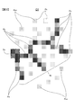
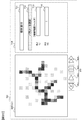
- FIG. 3 is a conceptual diagram showing an example of a captured image.
- the captured image G1 is composed of a plurality of pixels Px.
- the darker the hatched portion the higher the brightness of the pixel.
- the cell body So and the neurite Nr are shown as high-luminance portions.
- noise pixels Pxn which are pixels having brightness due to noise or the like in imaging, are also scattered in the captured image G1.
- the pixel signal corresponding to the linear portion such as the neurite Nr is weak, so that imaging cannot be performed with sufficient accuracy. In particular, this tendency can be seen in fluorescence microscopes that are often used for imaging cells and the like.
- the method of expressing the image in the captured image data is not particularly limited. For example, the larger the pixel value, the higher the brightness or saturation, or the smaller the pixel value, the higher the brightness or saturation.
- the nerve cells are evaluated by measuring numerical values such as the length (or width) of the neurite Nr and the number of branches.
- the image processing apparatus 1 of the present embodiment makes it easy to appropriately extract the neurite Nr by generating an image that emphasizes a linear portion in the captured image.
- the image processing apparatus 1 of the present embodiment can be used for various purposes such as using, extracting, or analyzing a linear portion in an image.
- a portion corresponding to the cell body So can be detected in advance from the captured image, and the portion can be masked to perform the following first image processing and the like.
- the cell body So can be appropriately detected by erasing the details of the captured image by an opening process, a closing process, or the like.
- the first pixel group setting unit 611 of the first image processing unit 61 sets a plurality of first pixel groups corresponding to the first pixel of the captured image G1.
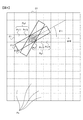
- FIG. 4 is a conceptual diagram for explaining the first image processing.
- the first pixel group setting unit 611 selects the first pixel Px1 from the pixels Px included in the captured image G1.
- the first pixel group setting unit 611 is the first pixel from the pixels included in the region (hereinafter, referred to as a target region) in which the first pixel Px1 is selected in the captured image G1 set in advance by the first image processing unit 61. Select and set Px1.
- the target area may be the entire captured image, but for example, when the pixel at the edge of the captured image G1 is the first pixel Px1, there may be no pixel corresponding to the one-dimensional filter described later. Therefore, in this case, it is preferable to appropriately replenish the virtual pixels around the captured image G1 so that the image processing described later is performed with desired accuracy.
- the target area should be set to a portion excluding the edge portion of about half the length of the one-dimensional filter from the captured image G1 so that there is no case where there is no pixel corresponding to the one-dimensional filter described later. Can be done.
- the first pixel group setting unit 611 sets a pixel group including the first pixel Px1 and arranged along a plurality of directions forming a predetermined angle with respect to the reference direction as the first pixel group Pg1.
- This predetermined angle is hereinafter referred to as a first angle ⁇ 1.
- the reference direction is the left-right direction of the captured image G1 (see arrow A10), but the reference direction is not particularly limited and may be any direction.
- FIG. 4 shows a plurality of pixels Px11, Px12, Px1, Px13 and Px14 included in the first pixel group Pg1 when the first angle ⁇ 1 is 0 °.
- the first pixel group Pg1 includes a plurality of pixels arranged in one direction and adjacent to each other in this way.
- the first angle ⁇ 1 is 45 ° and 90 °
- the first pixel group setting unit 611 sets a plurality of pixels arranged diagonally and vertically in the captured image G1 and adjacent to each other as the first pixel group Pg1. Can be done.
- the partial regions of the captured image G1 corresponding to the first pixel group Pg1 when the first angles ⁇ 1 are 0 °, 30 °, and 60 ° are schematically shown by the one-dimensional filters F1, F11, and F12, respectively. It was.
- the first pixel group Pg1 corresponding to the one-dimensional filters F11 and F12 the pixel overlapping with these one-dimensional filters and the pixel through which the straight line corresponding to these one-dimensional filters passes are included in the first pixel group Pg1. Can be done. However, since the pixels set in this way do not line up in a straight line, the accuracy drops a little.
- the first pixel group setting unit 611 centers the pixel corresponding to the first pixel in the image obtained by rotating the captured image G1 in the direction forming the first angle ⁇ 1 with respect to the reference direction. It is preferable to set a plurality of pixels arranged along a predetermined direction as the first pixel group Pg1.
- This predetermined direction is not particularly limited, and may be any direction such as a reference direction.
- the first pixel group setting unit 611 rotates the captured image G1 clockwise by ⁇ 1 while fixing the one-dimensional filter F1, and the vertical 1 within the range of the one-dimensional filter F1 in the obtained image.
- ⁇ A pixel having 5 pixels in the horizontal direction is set as the first pixel group Pg1.
- the first pixel group Pg1 corresponding to the one-dimensional filter F11 in the captured image G1 before rotation can be set more precisely than in the case where the first pixel group Pg1 is set by rotating the one-dimensional filter.
- the first pixel group setting unit 611 sets the first pixel group Pg1 for each of the plurality of first angles ⁇ 1.
- a plurality of first angles ⁇ 1 are set for each predetermined angle selected from a range of, for example, 1 ° to 45 °.
- the first pixel group setting unit 611 can set a plurality of first angles ⁇ 1 from 0 ° to 179 ° for each 1 °, and can set the first pixel group Pg1 for each first angle ⁇ 1.
- the number of pixels constituting the first pixel group Pg1 is not particularly limited as long as it is 2 or more.
- the number of the pixels can be set based on the curvature or radius of curvature of the linear portion in the captured image G1.
- the first pixel group Pg1 may be a pixel group composed of a plurality of columns such as a pixel block of 2 pixels ⁇ 5 pixels. In this case, it is preferable that the number of pixels arranged in one direction exceeds twice the number of pixels arranged in the other direction.
- the first calculation unit 612 of the first image processing unit 61 calculates the first candidate pixel value based on the pixel values of the pixels included in the first pixel group Pg1.
- the first candidate pixel value is a value that is a candidate for a pixel value set in the second pixel corresponding to the first pixel Px1 in the first emphasized image.
- the pixel value set for the second pixel is selected from a plurality of first candidate pixel values.
- the first calculation unit 612 calculates the average value of the pixel values of the pixels included in the first pixel group Pg1 and uses it as the first candidate pixel value. For example, the first calculation unit 612 calculates the arithmetic mean of the pixels of the pixels Px11, Px12, Px1, Px13 and Px14 corresponding to the one-dimensional filter F1, and the first of the first pixel group Pg1 corresponding to the one-dimensional filter F1. Use as a candidate pixel value. The first calculation unit 612 calculates the first candidate pixel value for each first pixel group Pg1 set by the first pixel group setting unit 611.
- the first calculation unit 612 calculates the first candidate pixel value for the first pixel group Pg1 corresponding to each of the plurality of first angles ⁇ 1.
- the first calculation unit 612 may calculate the average value of the pixel values of the pixels included in the first pixel group Pg1 as the first candidate pixel value by an average other than the arithmetic mean such as the geometric mean.
- the first calculation unit 612 sets the sum of the pixel values of the pixels included in the first pixel group Pg1 and the value adjusted by appropriate standardization or the like according to the numerical range in which the sum can be set as the pixel value. It can be set as the first candidate pixel value.
- the first candidate pixel value can be set based on the overall size of the pixel values of the pixels included in the first pixel group Pg1 as in the sum or average, it is set by the first calculation unit 612.
- the calculation method of the first candidate pixel value is not particularly limited.
- the first pixel value setting unit 613 of the first image processing unit 61 is a second pixel in the first emphasized image corresponding to the first pixel Px1 from a plurality of first candidate pixel values calculated for the first pixel Px1. Set the pixel value.
- the first pixel value setting unit 613 can set the largest value among the plurality of first candidate pixel values for the first pixel Px1 to the pixel value of the corresponding second pixel. This means that in the first image processing, among the one-dimensional filters F, F11, and F12 in a plurality of directions, the pixel value by the one-dimensional filter corresponding to the direction in which the pixel having the highest pixel value is arranged is the first emphasized image. Will be reflected in. As a result, when the higher the pixel value, the higher the possibility that the pixel corresponds to a linear portion such as a neurite Nr, smoothing can be performed and the linear portion can be emphasized.
- the first pixel value setting unit 613 can set the smallest value among the plurality of first candidate pixel values for the first pixel Px1 to the pixel value of the corresponding second pixel.
- the pixel value of the second pixel may be set in the range of 0.8 times to 1.2 times, preferably 0.9 times to 1.1 times, the largest value or the smallest value. .. Even in such a case, the linear portion can be emphasized with a certain degree of accuracy.
- the captured image G1 The first image processing is performed with a pixel different from the first pixel Px1 in the target region as the first pixel Px1.
- the first image processing unit 61 performs the first image processing on each pixel included in the target area.
- the first pixel group setting unit 611 and the first calculation unit 612 fix the first angle ⁇ 1 and use a one-dimensional filter in the direction corresponding to the first angle ⁇ 1 for each first pixel Px1 in the target area.
- the first candidate pixel value may be calculated.
- the first pixel group setting unit 611 and the first calculation unit 612 change the first angle ⁇ 1 and fix it again, and similarly calculate the first candidate pixel value of each first pixel Px1.
- the first pixel value setting unit 613 determines the pixel value of the second pixel corresponding to each first pixel Px1. Can be calculated. As described above, if the pixel value of the corresponding second pixel can be calculated for each pixel Px in the setting area, the order of calculation and the like are not particularly limited.
- the second image processing unit 62 of the data processing unit 51 performs image processing on the captured image data corresponding to the captured image G1 to generate the two-dimensional smoothed image data corresponding to the two-dimensional smoothed image.
- this image processing by the second image processing unit 62 is referred to as a second image processing.
- the two-dimensional smoothed image is an image obtained by smoothing the captured image G1 with a two-dimensional filter corresponding to pixels arranged along at least two directions. In the two-dimensional filter, it is preferable that the number of pixels arranged in one direction is twice or less the number of pixels arranged in the other direction.
- the second image processing unit 62 sets the pixel value of the two-dimensional smoothed image corresponding to each pixel in the captured image G1.
- the pixel in the two-dimensional smoothed image corresponding to the first pixel Px1 in the captured image G1 is referred to as a third pixel.
- the second pixel group setting unit 621 of the second image processing unit 62 sets a plurality of second pixel groups corresponding to the first pixel Px1 of the captured image G1.
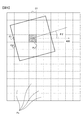
- FIG. 5 is a conceptual diagram for explaining the second image processing.
- the second pixel group setting unit 621 selects the first pixel Px1 from the pixels Px included in the captured image G1.
- the second pixel group setting unit 621 selects and sets the first pixel Px1 from the pixels included in the target area.
- the second pixel group setting unit 621 includes a first pixel Px1 and moves a two-dimensional filter F2 including rotation of a predetermined angle with respect to a reference direction to obtain a pixel group corresponding to the two-dimensional filter. It is set as a two-pixel group Pg2.
- the second pixel group Pg2 is a pixel group arranged along at least two directions in which the pixel groups arranged along at least two directions are rotated by a predetermined angle in the at least two directions. ..
- the second pixel group setting unit 621 sets a plurality of second pixel groups Pg2 for each of the plurality of predetermined angles. This predetermined angle is hereinafter referred to as a second angle ⁇ 2.
- the reference direction is the left-right direction of the captured image G1 (see arrow A20), but the reference direction is not particularly limited.
- the reference direction may be any direction and may be different from the reference direction in the above-described first image processing.
- the two-dimensional filter F2 corresponds to a square pixel block of 5 vertical pixels ⁇ 5 horizontal pixels
- the second pixel group Pg2 corresponding to the two-dimensional filter F2 is the 5 ⁇ centered on the first pixel Px1. Includes 5 pixels.
- the shape of the two-dimensional filter F2 corresponding to the second pixel group Pg2 is not particularly limited.
- the second pixel group Pg2 preferably includes a plurality of pixels adjacent to each other.
- the partial regions of the captured image G1 corresponding to the second pixel group Pg2 when the second angle ⁇ 2 is 0 ° and about 20 ° are schematically shown by the two-dimensional filters F2 and F21, respectively.
- the pixels and the like overlapping with the two-dimensional filter F21 can be included in the second pixel group Pg2.
- the pixels set in this way have a slightly lower accuracy because the shape of the pixel block corresponding to the second pixel group Pg2 varies.
- the second pixel group setting unit 621 centers on the pixel corresponding to the first pixel in the image obtained by rotating the captured image G1 in the direction forming the second angle ⁇ 2 with respect to the reference direction. It is preferable to set a plurality of pixels arranged along at least two directions as the second pixel group Pg2.
- the second pixel group setting unit 621 rotates the captured image G1 clockwise by ⁇ 2 while fixing the two-dimensional filter F2, and the vertical 5 within the range of the two-dimensional filter F2 in the obtained image.
- ⁇ A pixel of 5 pixels in the horizontal direction is set as the second pixel group Pg2.
- the second pixel group Pg2 corresponding to the two-dimensional filter F21 in the captured image G1 before rotation can be set more precisely than in the case where the second pixel group Pg2 is set by rotating the two-dimensional filter F2. ..
- the second pixel group setting unit 621 sets the second pixel group Pg2 for each of the plurality of second angles ⁇ 2.
- a plurality of the plurality of second angles ⁇ 2 are set for each predetermined angle selected from a range of, for example, 1 ° to 45 °.
- the second pixel group setting unit 621 can set a plurality of second angles ⁇ 2 from 0 ° to 179 ° for each 1 °, and can set the second pixel group Pg2 for each second angle ⁇ 2.
- the second calculation unit 622 of the second image processing unit 62 calculates the second candidate pixel value based on the pixel value of the pixel included in the second pixel group Pg2.
- the second candidate pixel value is a value that is a candidate for a pixel value set in the third pixel corresponding to the first pixel Px1 in the second emphasized image.
- the pixel value set for the third pixel is selected from a plurality of second candidate pixel values.
- the second calculation unit 622 calculates the average value of the pixel values of the pixels included in the second pixel group Pg2 and uses it as the second candidate pixel value. For example, the second calculation unit 612 calculates the arithmetic mean of the pixel values of the 5 ⁇ 5 pixels corresponding to the two-dimensional filter F2, and sets the second candidate pixel value of the second pixel group Pg2 corresponding to the two-dimensional filter F2. To do. The second calculation unit 622 calculates the second candidate pixel value for each second pixel group Pg2 set by the second pixel group setting unit 621. The second calculation unit 622 calculates the second candidate pixel value for the second pixel group Pg2 corresponding to each of the plurality of second angles ⁇ 2.
- the second calculation unit 612 may calculate the average value of the pixel values of the pixels included in the second pixel group Pg2 as the second candidate pixel value by an average other than the arithmetic mean such as the geometric mean.
- the second calculation unit 622 sets the sum of the pixel values of the pixels included in the second pixel group Pg2 and the value adjusted by appropriate standardization or the like according to the numerical range in which the sum can be set as the pixel value. It can be set as the second candidate pixel value. If the second candidate pixel value can be set based on the overall size of the pixel values of the pixels included in the second pixel group Pg2 as in the sum or average, it is set by the second calculation unit 622.
- the calculation method of the second candidate pixel value is not particularly limited.
- the second pixel value setting unit 623 of the second image processing unit 62 is a third pixel in a two-dimensional smoothed image corresponding to the first pixel Px1 from a plurality of second candidate pixel values calculated for the first pixel Px1. Set the pixel value of.
- the second pixel value setting unit 623 can set the largest value among the plurality of second candidate pixel values for the first pixel Px1 to the pixel value of the corresponding third pixel. This means that in the second image processing, among the two-dimensional filters F2 and F21 corresponding to the plurality of second angles ⁇ 2, the pixel value by the two-dimensional filter including the pixel having the highest pixel value as a whole is two-dimensionally smoothed. It will be reflected in the image. As a result, when the higher the pixel value, the higher the brightness, smoothing that is not biased in a specific direction can be effectively performed.
- the second pixel value setting unit 623 can set the smallest value among the plurality of second candidate pixel values for the first pixel Px1 to the pixel value of the corresponding third pixel.
- the pixel value of the third pixel may be set in the range of 0.8 times to 1.2 times, preferably 0.9 times to 1.1 times, the largest value or the smallest value. .. Even in such a case, smoothing that is not biased in a specific direction can be performed with a certain degree of accuracy.
- the captured image G1 The second image processing is performed with a pixel different from the first pixel Px1 in the target region as the first pixel Px1.
- the second image processing unit 61 performs the second image processing on each pixel included in the target area.
- the order of calculation is not particularly limited as long as the pixel value of the corresponding third pixel can be calculated for each pixel Px in the setting area.
- the first removing unit 64 removes at least a part of the non-linear portion in the first emphasized image based on the two-dimensional smoothed image data, and the second emphasis corresponds to the second emphasized image.
- “removal” refers to removing a component of a pixel value that does not contribute to showing a non-linear portion in the first emphasized image.
- the first removing unit 64 generates an image in which the absolute value of the difference obtained by subtracting the pixel value of the two-dimensional smoothed image from the pixel value of the first emphasized image is the pixel value as the second emphasized image. be able to.
- a second emphasized image which is an enhanced image in which the linear portion is further emphasized by removing the spread of brightness and noise having low direction dependence from the first emphasized image, can be obtained.
- the binarization unit 65 binarizes the pixel values of the second emphasized image by a plurality of threshold values appropriately different for each portion based on the pixel values of the pixels included in each portion of the second emphasized image. I do.
- the binarization unit 65 divides the second emphasized image into a plurality of regions. These areas are called divided areas.
- the binarization unit 65 calculates, for each divided region, the average value of the pixel values of the pixels included in the divided region based on the arithmetic mean and the like, and the standard deviation of the pixel values.
- the binarization threshold by the binarization unit 65 is called the binarization threshold Th.
- the binarization unit 65 stores the detection result image data obtained by performing the above binarization of the second emphasized image data in the storage unit 43 or the like.
- the binarization unit 65 may store the data obtained by performing the above binarization of the first emphasized image data in the storage unit 43 or the like as the detection result image data. In this case, it is not necessary to perform the above-mentioned second image processing and the processing of the first removing unit 64.
- the linear portion can be emphasized with a desired accuracy by the first image processing without performing the second image processing and the processing by the first removing unit 64.
- the data processing unit 51 can appropriately perform image processing such as level correction for removing a relatively dark portion in the image before the binarization processing by the binarization unit 65.
- the data processing unit 51 can detect the neurite Nr in the detection result image, detect the crossover, or analyze which cell the fragment of the linear portion is connected to as appropriate. Further, the data processing unit 51 analyzes the length of the neurite Nr and the like, and can evaluate the state of the cultured or cultured cell Ce based on the data obtained by this analysis. ..
- the output control unit 52 generates an output image to be output to the output unit 44 based on the detection result image data, and causes the output unit 44 to output the output image.
- the output control unit 52 displays the detection result image on the display monitor of the output unit 44.
- the device control unit 53 of the control unit 50 controls each unit of the culture unit 100 based on the input from the input unit 41 or the like (arrow A2).
- the device control unit 53 executes control related to cell culture (eg, control of the culture chamber 10 that controls temperature or humidity, control of the drive unit 12), or causes the image pickup unit 20 to perform imaging.
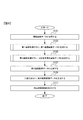
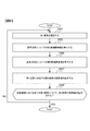
- FIG. 6 is a flowchart showing the flow of the image processing method according to the present embodiment.
- the data processing unit 51 acquires the captured image data obtained by the imaging of the imaging unit 20.
- step S103 is started.
- step S103 the first image processing unit 61 performs the first image processing on the captured image data to generate the first emphasized image data.
- step S105 is started.
- step S105 the second image processing unit 62 performs the second image processing on the captured image data to generate the two-dimensional smoothed image data.
- step S107 the first removing unit 64 generates the second emphasized image data from the first emphasized image data and the two-dimensional smoothed image data.
- step S109 is started.
- step S109 the binarization unit 65 binarizes the second emphasized image data and generates the detection result image data.
- step S111 is started.
- step S111 the output control unit 52 displays the detection result image on the output unit 44.
- FIG. 7 is a flowchart showing the flow of step S103 (first image processing) in the flowchart of FIG.
- step S201 is started.
- the first pixel group setting unit 611 selects the first pixel Px1 in which the pixel value of the corresponding second pixel is not set from the target area.
- step S203 is started.
- step S203 the first pixel group setting unit 611 sets the first pixel group Pg1 included in the one-dimensional filter F1 extending in the reference direction, and the first calculation unit 612 sets the first candidate pixel value in the reference direction. calculate.
- step S205 the first pixel group setting unit 611 rotates the one-dimensional filter or generates data obtained by rotating the captured image, sets the first pixel group Pg1 for each first angle ⁇ 1, and sets the first pixel group Pg1.
- the calculation unit 612 calculates the first candidate pixel value for each first angle ⁇ 1.
- step S207 is started.
- step S207 the first pixel value setting unit 613 sets the pixel value of the second pixel corresponding to the first pixel Px1 from the first candidate pixel value for the first pixel Px1.
- step S209 is started.
- the order of steps S203, S205 and S207 may be changed as appropriate.
- step S209 the data processing unit 51 determines whether or not the pixel value of the second pixel corresponding to the first pixel Px1 is set for all the first pixel Px1 in the target area.
- the data processing unit 51 affirms step S209 and starts step S105.
- the data processing unit 51 negatively determines step S209 and starts step S201.
- FIG. 8 is a flowchart showing the flow of step S105 (second image processing) in the flowchart of FIG.
- step S301 is started.
- the second pixel group setting unit 621 selects the first pixel Px1 in which the pixel value of the corresponding third pixel is not set from the target area.
- step S303 is started.
- step S303 the second pixel group setting unit 621 sets the second pixel group Pg2 included in the two-dimensional filter F2 for the reference direction, and the second calculation unit 622 sets the second candidate pixel value for the reference direction. calculate.
- step S305 the second pixel group setting unit 621 rotates the two-dimensional filter or generates data obtained by rotating the captured image, sets the second pixel group Pg2 for each second angle ⁇ 2, and sets the second pixel group Pg2.
- the calculation unit 622 calculates the second candidate pixel value for each second angle ⁇ 2.
- step S307 is started.
- step S307 the second pixel value setting unit 623 sets the pixel value of the third pixel corresponding to the first pixel Px1 from the second candidate pixel value for the first pixel Px1.
- step S309 is started.
- the order of steps S303, S305 and S307 may be changed as appropriate.
- step S309 the data processing unit 51 determines whether or not the pixel value of the third pixel corresponding to the first pixel Px1 is set for all the first pixel Px1 in the target area.
- the data processing unit 51 affirms step S309 and starts step S107.
- the data processing unit 51 negatively determines step S309 and starts step S301.
- the image processing device 1 of the present embodiment is positioned at a position corresponding to the first pixel Px1 of the captured image G1 in the enhanced image (second image) obtained by image processing the captured image (first image) G1.
- a first image processing unit 61 for setting the pixel value of the second pixel of the emphasized image is provided, and the first image processing unit 61 is a plurality of first pixel groups Pg1 set corresponding to the first pixel Px1. Therefore, the captured image G1 is arranged along a plurality of directions (first angle ⁇ 1) different from each other with respect to a predetermined direction (reference direction of the image), or the captured image G1 is predetermined.
- the first pixel group setting unit 611, and the first calculation unit 612 that calculates a plurality of first candidate pixel values based on the size of the pixel values of the pixels included in each of the plurality of first pixel groups Pg1. It includes a first pixel value setting unit 613 that sets the pixel value of the second pixel of the emphasized image based on the plurality of first candidate pixel values. This makes it possible to effectively emphasize the linear portion of the cell in the image.
- the first calculation unit 612 has a plurality of first candidate pixels based on the sum or average of the pixel values of the pixels included in each of the plurality of first pixel groups Pg1. The value can be calculated. This makes it possible to detect the direction in which pixels with high pixel values are lined up and more effectively emphasize the linear portion in the image.
- the first calculation unit 612 calculates the first candidate pixel value for the first pixel group Pg1 by using the smoothing filters F1, F11, and F12. Thereby, the linear portion based on the length of the smoothing filter can be detected, and the linear portion in the image can be emphasized more effectively.
- the one-dimensional filters F1, F11, and F12 are one-dimensional smoothing filters.
- the linear portion can be detected by the shape of the one-dimensional filter (eg, the shape including the length and the thickness), and the linear portion in the image can be emphasized more effectively.
- the first pixel setting unit 611 for setting the first pixel Px1 from the pixels constituting the captured image G1 is provided, and the first pixel value setting unit 611 has a plurality of first pixels. 1. Set a value 0.8 to 1.2 times the largest value of the candidate pixel values, or 0.8 to 1.2 times the smallest value, as the pixel value of the second pixel. Can be done. This makes it possible to detect the direction in which pixels with high or low pixel values are lined up and more effectively emphasize the linear portion in the image.
- the second pixel group setting unit 623 is a two-dimensional filter at a plurality of angles (second angle ⁇ 2) different from a predetermined direction (reference direction) in the captured image G1. At least in each of the captured images G1 arranged along at least two directions obtained by rotating at least two directions in which the pixels are arranged in the above, or rotated at a plurality of different angles (second angle ⁇ 2). A plurality of second pixel groups Pg2 arranged along the two directions are set, and the second image processing unit 62 is based on the sum or average of the pixel values of the pixels included in each of the plurality of second pixel groups Pg1.
- a second calculation unit 622 for calculating a plurality of second candidate pixel values is provided, and the second pixel value calculation unit 623 sets the pixel value of the third pixel based on the plurality of second candidate pixel values.
- the image processing apparatus 1 of the present embodiment includes a first removing unit 64 that removes at least a part of a non-linear portion in the enhanced image based on the two-dimensional smoothed image.
- a first removing unit 64 that removes at least a part of a non-linear portion in the enhanced image based on the two-dimensional smoothed image.
- the image processing device 1 of the present embodiment binarizes the pixel values of the emphasized image by a plurality of different binarization thresholds Th based on the pixel values of the pixels included in each part of the emphasized image.
- the binarization unit 64 to be performed is provided. As a result, whether or not each pixel in the image corresponds to a linear portion can be easily indicated by binarization and can be easily analyzed.
- the captured image G1 is an image of the neurite Nr. This makes it possible to effectively emphasize the portion of the image corresponding to the neurite Nr. In addition, the length of the neurite Nr and the like can be analyzed more accurately by using the image in which the neurite Nr is emphasized.
- the image pickup apparatus includes the above-mentioned image processing apparatus 1 and an image pickup unit 20 that images a cell or the like including a linear portion. As a result, the linear portion in the captured image can be effectively emphasized.
- the above-mentioned image processing device 1 which is the culture device according to the present embodiment includes a culture unit 100 for culturing cells. This makes it possible to effectively emphasize the linear portion in the image of the cells Ce cultured in the undifferentiated state or the differentiated state.
- the image processing method in the emphasized image (second image) obtained by image processing the captured image (first image) G1, the position corresponding to the first pixel Px1 of the captured image G1 A certain pixel value of the second pixel of the captured image G1 is set, and the pixel value of the second pixel is set by a plurality of first pixel groups Pg1 set corresponding to the first pixel Px1.
- the captured image G1 is arranged along a plurality of different angles (first angle ⁇ 1) with respect to a predetermined direction (reference direction), or the captured image G1 is arranged at a plurality of different angles (first angle ⁇ 1).
- the second image processing unit 62 does not perform the process of moving and rotating the two-dimensional filter or the captured image G1, and is calculated from the pixels included in one two-dimensional filter.
- the second candidate pixel value may be the pixel value of the third pixel. Even in such a case, if the two-dimensional filter originally has a shape with a small bias in a specific direction, smoothing that is not biased in the specific direction can be performed with a certain degree of accuracy.
- the image processing device 1 of this modified example sets the pixel value of the third pixel at the position corresponding to the first pixel Px1 in the two-dimensional smoothed image obtained by image processing the captured image G1.
- the second image processing unit 62 includes a unit 62, and the second image processing unit 62 is set corresponding to the first pixel Px1 and sets a second pixel group Pg2 including pixels arranged along at least two directions.
- a unit 621 and a second pixel value setting unit 623 that sets the pixel value of the third pixel based on the sum or average of the pixel values of the pixels included in the second pixel group Pg2.
- the image processing apparatus 1 may be configured to generate information as to whether or not the first pixel Px1 in the captured image G1 corresponds to the linear portion by using a one-dimensional filter.
- this information will be referred to as pixel correspondence information with respect to the linear portion (eg, neurite Nr).
- FIG. 9 is a conceptual diagram showing the configuration of the data processing unit 51a in the image processing device of this modified example.
- the data processing unit 51a is different from the above-mentioned data processing unit 51 in that the data processing unit 51a includes the pixel information processing unit 63.
- the pixel information processing unit 63 includes a third pixel group setting unit 631, an information generation unit 632, and a processing control unit 633.
- the pixel information processing unit 63 acquires information from the captured image data using a one-dimensional filter and processes the information.
- the third pixel group setting unit 631 sets a plurality of third pixel groups Pg3 corresponding to the first pixel Px1 in the captured image G1. Similar to the setting of the plurality of first pixel groups Pg1 by the first pixel group setting unit 631 described above, the third pixel group setting unit 631 uses a plurality of one-dimensional filters F1, F11, F12 corresponding to a plurality of angles. The third pixel group Pg3 is set.
- FIG. 10 is a conceptual diagram for explaining the third pixel group Pg3.
- the third pixel group setting unit 631 selects the first pixel Px1 from the pixels Px included in the captured image G1.
- the third pixel group setting unit 631 selects and sets the first pixel Px1 from the pixels included in the target area.
- the third pixel group setting unit 631 sets a pixel group including the first pixel Px1 and arranged along a plurality of directions forming a predetermined angle with respect to the reference direction as the third pixel group Pg3.
- This predetermined angle is hereinafter referred to as a third angle ⁇ 3.
- the reference direction is the left-right direction of the captured image G1 (see arrow A30), but the reference direction is not particularly limited and may be any direction.
- a plurality of pixels Px31, Px32, Px1, Px33 and Px34 included in the third pixel group Pg3 when the third angle ⁇ 3 is 0 ° are shown. It is preferable that the third pixel group Pg3 includes a plurality of pixels arranged in one direction and adjacent to each other in this way.
- the third pixel group setting unit 631 corresponds to the first pixel in the image obtained by moving the captured image G1 including rotation in the direction forming the third angle ⁇ 3 with respect to the reference direction. It is preferable to set a plurality of pixels arranged along a predetermined direction centered on the pixels as the third pixel group Pg3. This predetermined direction is not particularly limited, and may be any direction such as a reference direction. As a result, it is possible to set the third pixel group Pg3 more precisely than when the one-dimensional filter F1 is moved including rotation to set the third pixel group Pg3.
- the third pixel group setting unit 631 sets the third pixel group Pg3 for each of the plurality of third angles ⁇ 3.
- a plurality of the plurality of third angles ⁇ 3 are set for each predetermined angle selected from a range of, for example, 1 ° to 45 °.
- the third pixel group setting unit 631 can set a plurality of third angles ⁇ 3 from 0 ° to 179 ° for each 1 °, and can set the third pixel group Pg3 for each third angle ⁇ 3.
- the third pixel group setting unit 631 sets the third pixel group Pg3 for each first pixel Px1 in the target area.
- the information generation unit 632 generates the above-mentioned corresponding information.
- the information generation unit 632 calculates the sum or average of the pixel values, which is a value representing the overall size of the pixel values of the pixels included in each of the plurality of third pixel groups Pg3. As this average, an arithmetic mean or the like can be used as appropriate.
- the sum or average of the calculated pixel values is referred to as a one-dimensional filter value.
- FIG. 11 is a conceptual diagram showing a one-dimensional filter corresponding to the third angle ⁇ 3 and a linear partial LP for a plurality of third angles ⁇ 3.
- FIG. 11 shows a one-dimensional filter F100 when the third angle ⁇ 3 is 0 °, a one-dimensional filter F110 when the third angle ⁇ 3 is 30 °, and a one-dimensional filter F120 when the third angle ⁇ 3 is 60 °.
- a one-dimensional filter F130 when the third angle ⁇ 3 is 90 °, a one-dimensional filter F140 when the third angle ⁇ 3 is 120 °, and a one-dimensional filter F150 when the third angle ⁇ 3 is 150 ° are shown.
- the first pixel Px1 is located on the linear portion LP, it is a pixel corresponding to the linear portion.
- the pixel value of the pixel corresponding to the linear partial LP is the pixel value of the nearby pixel that does not correspond to the linear portion. Is higher than.
- the one-dimensional filter value which is the sum or average value of the pixel values of the pixels corresponding to the one-dimensional filter, becomes the highest.
- the third angles ⁇ 3 are 0 °, 120 °, and 150 °
- the overlap between the one-dimensional filters F100, F140, and F150 and the linear partial LP is small, and the one-dimensional filter value is the other third angle. It is smaller than the case of ⁇ 3.
- the third angle ⁇ 3 is 30 ° or 90 °
- the one-dimensional filter F110 or the one-dimensional filter F130 and the linear partial LP have an overlap of about 3 out of 5 pixels constituting the one-dimensional filter. Therefore, the one-dimensional filter value is larger than when the third angle ⁇ 3 is 0 °, 120 °, or 150 °.
- the third angle ⁇ 3 is 60 °
- the one-dimensional filter F120 and the linear partial LP substantially overlap each other, and in the case shown in FIG. 11, the one-dimensional filter value is the highest.
- the information generation unit 632 generates data in which the third angle ⁇ 3 and the one-dimensional filter value are associated with each other. This data will be referred to as filter value data below.
- the filter value data may be generated by appropriately smoothing or approximating with a curve. As a result, the influence of noise and the like can be reduced and the accuracy can be improved.
- FIG. 12 is a graph showing a one-dimensional filter value for a third angle ⁇ 3 in the first pixel Px1 that can be generated from the filter value data.
- FIG. 12 assumes a case where the one-dimensional filter value as shown in FIG. 11 has an angle dependence.
- the one-dimensional filter value takes a value from Vmin to Vmax, and the one-dimensional filter value becomes the highest when the third angle ⁇ 3 is about 60 °.
- the information generation unit 632 can calculate the peak width of the third angle ⁇ 3 and the peak P1 related to the third angle ⁇ 3, which have the highest one-dimensional filter value.
- the information generation unit 632 can detect the peak based on the difference between Vmax and Vmin, whether or not the S / N ratio or the like is equal to or more than a predetermined value, and the like.
- FIG. 13 is a graph showing a one-dimensional filter value with respect to the third angle ⁇ 3 when there is no remarkable peak.
- the fluctuation of the one-dimensional filter value is smaller than that of the S / N ratio, no peak is detected.
- the characteristics of the subject in the first pixel Px1 can be analyzed by the number of peaks.
- the first pixel Px1 is a portion that does not correspond to a line or an intersection.
- the first pixel Px1 corresponds to the linear portion.
- the number of peaks is two, the first pixel Px1 corresponds to the crossover.
- the information generation unit 632 generates correspondence information as to whether or not the first pixel Px1 corresponds to the linear portion by analyzing such a one-dimensional filter value.
- the information generation unit 632 can binaryly indicate whether or not each pixel in the captured image corresponds to a linear portion, generate correspondence information associated with each pixel, and store it in the storage unit 43 or the like. .. Further, the information generation unit 632 may also generate information on whether or not each pixel in the captured image corresponds to the crossover.
- the information generation unit 632 generates filter value data and correspondence information for each first pixel Px1 in the target region.
- the third pixel group setting unit 631 sets the third pixel group Pg3 by increasing the interval between the plurality of third angles ⁇ 3, and when a peak is detected, the peak is concerned.
- the third pixel group Pg3 can be set by reducing the interval between the third angle ⁇ 3 and its vicinity.
- the information generation unit 632 can accurately calculate the one-dimensional filter value of the peak and its vicinity, and can efficiently analyze the angle dependence of the one-dimensional filter value.
- the processing control unit 633 (FIG. 9) controls the process of setting the first pixel group Pg1 of the first pixel group setting unit 611 based on the correspondence information.
- the processing control unit 633 changes the number of the third angles ⁇ 3 set in the first image processing according to the position of the first pixel Px1 based on the correspondence information.
- the processing control unit 633 can set a smaller number of third angles ⁇ 3 in the pixels that do not correspond to the linear portion than in the pixels that correspond to the linear portion.
- the processing control unit 633 can be set so that the first image processing is not performed on the pixels that do not correspond to the linear portion.
- the processing control unit 633 can set the first image processing so that the first pixel group setting unit 611 selects the first pixel Px1 from the pixels corresponding to the linear portion. In this way, by setting the pixels corresponding to the linear portion to perform the first image processing more precisely, the linear portion in the image can be emphasized more efficiently.
- the processing control unit 633 prevents the first image processing from being performed on the pixel corresponding to the crossover. Etc., the conditions for the first image processing can be set as appropriate based on the information.
- FIG. 14 is a flowchart showing the flow of the image processing method of this modified example.
- the description of step S401 is omitted because it corresponds to step S101 of the flowchart of FIG.
- step S403 is started.
- the information generation unit 632 generates information (correspondence information) as to whether or not the pixels included in the captured image G1 correspond to the linear portion.
- step S405 is started.
- step S405 the processing control unit 633 sets the conditions for the first image processing based on the correspondence information generated in step S403.
- step S407 is started.
- the first image processing unit 61 performs the first image processing based on the conditions set in step S403 to generate the first emphasized image data.
- step S409 is started. Since steps S409 to S415 correspond to steps 105 to S111 in the flowchart of FIG. 6, description thereof will be omitted.
- a plurality of third pixel groups Pg1 set corresponding to the first pixel Px1 in a predetermined direction (reference direction) of the captured image (first image) G1.
- a plurality of images are arranged along a plurality of directions forming a plurality of angles (third angle ⁇ 3) with respect to the image, or a plurality of images obtained by rotating the captured image G1 at a plurality of angles (third angle ⁇ 3).
- the image processing device of this modification includes a processing control unit that controls a process of setting the first pixel group Pg1 of the first pixel group setting unit 611 based on the corresponding information generated by the information generation unit 632. .. As a result, the first image processing can be performed more efficiently by using the generated information.
- the number of a plurality of angles (first angle ⁇ 1) when the first pixel group setting unit 611 sets a plurality of first pixel groups Pg1 is the first pixel Px1.
- the processing control unit 633 can set the above number at each position of the captured image G1 based on the corresponding information. Thereby, the precision of the first image processing can be controlled by the position in the captured image by using the generated information.
- the processing control unit 633 performs a process in which the first pixel group setting unit 611 sets the first pixel group Pg1 at each position of the captured image G1 based on the corresponding information. You can decide whether or not to do it. As a result, the first image processing can be performed even more efficiently by using the generated information.
- the data processing unit 51a may be configured to include a second removing unit that removes at least a part of a non-linear portion in the first emphasized image or the second emphasized image based on the corresponding information.
- the second removing unit sets the pixel value to 0 or the like for the pixel that does not correspond to the linear portion in the correspondence information, and sets the value corresponding to the case where the subject does not exist. As a result, the linear portion in the image can be further emphasized.
- the target area may be set by the user via the input unit 41.
- FIG. 15 is a conceptual diagram showing the target area R1.
- the user can input the range of the target area R1 by, for example, dragging the mouse as the input unit 41 while looking at the display screen of the output unit 44 on which the captured image G1 is displayed.
- the image processing device of this modification includes an input unit 41 for the first image processing unit 61 to input the position or range of the first pixel Px1 to be image processed.
- the subject of the captured image G1 is defined as a cell Ce, and the linear portion to be emphasized is described as a neurite Nr.
- the object to be emphasized is not limited to this example.
- the subject of the captured image G1 is the fundus and the linear portion to be emphasized is the blood vessel in the fundus, and it is even more preferable that the blood vessel of the retina or the choroidal blood vessel is used.
- the captured image G1 is an image of a blood vessel. This makes it possible to effectively emphasize the linear portion in the image of the blood vessel.
- the output unit 44 can output a display screen for the user to select and display at least one of the captured image G1 and the emphasized image by controlling the output control unit 52. ..
- This display screen is called a first display screen.
- the emphasized image may be either a first emphasized image or a second emphasized image.
- FIG. 16 is a conceptual diagram showing an example of the first display screen of this modified example.
- the first display screen 70 includes an image selection unit 71 and a first image display unit 72 that displays at least one of the captured image G1 and the emphasized image.
- the image selection unit 71 is composed of a combo box, and the combo box is configured so that the display or non-display of the list 71b can be switched each time the icon 71a is selected.
- Listing 71b includes a first input element 71c, a second input element 71d, and a third input element 71e. When the user clicks the first input element 71c using a mouse or the like, the captured image G1 which is an input image is displayed on the first image display unit 72, and the emphasized image G2 is not displayed.
- the image selection unit 71 can be configured to include an arbitrary image element, not limited to the combo box.
- the effect of the image processing method of the above-described embodiment can be shown to the user in an easy-to-understand manner.
- the number of the plurality of first angles ⁇ 1 may be set by the user.
- the output unit 44 can output a display screen for allowing the user to set the number of a plurality of first angles ⁇ 1. This display screen is called a second display screen.
- FIG. 17 is a conceptual diagram showing an example of the second display screen of this modified example.
- the second display screen 80 includes a first angle input unit 81, a second image display unit 82 for displaying the captured image G1, and a first execution unit 83.
- the first angle input unit 81 includes a text box 810.
- the first angle input unit 81 is an element for inputting the number of first angles ⁇ 1.
- the user can input a numerical value indicating the number of the first angle ⁇ 1 into the text box 810 by using a keyboard or the like.
- the user can input while appropriately viewing the captured image G1 displayed on the second image display unit 82. If the number of the first angles ⁇ 1 can be input, the image element for input is not particularly limited to the text box, and the user may select from the displayed numerical value candidates.
- the first execution unit 83 is a button for setting the number of first angles ⁇ 1 input by the user and causing the image processing device 1 to start the first image processing.
- the first pixel group setting unit 611 divides, for example, 180 ° by the numerical value input to the text box 810 to obtain a plurality of first angles for each angle. Set ⁇ 1 and perform the first image processing.
- the parameter can be set more appropriately by setting the parameter (setting information) for the first angle ⁇ 1 while the user appropriately looks at the captured image G1. If the user can set the conditions for the first angle ⁇ 1, the second angle ⁇ 2, or the third angle ⁇ 3, the case is not limited to the case of inputting the number of angles as in this modification.
- Modification 7 the user can appropriately input or change the parameters for the first image processing by looking at the display screen of the output unit 44 for the first image processing.
- FIG. 18 is a flowchart showing the flow of the image processing method of this modified example. Since step S501 is the same as step S101 in the flowchart of FIG. 6, the description thereof will be omitted. When step S501 is completed, step S503 is started.
- the first image processing unit 61 sets the parameters in the first image processing based on the input of the user.
- This parameter is called the first parameter.
- the first parameter can be a numerical value indicating the length and thickness of the one-dimensional filters F1, F11, and F12 in the first image processing.
- the user can see the captured image G1 and, if the above-mentioned first image processing to binarization have already been performed, see the detection result image and input the first parameter.
- step S505 is started.
- the second image processing unit 62 may be configured to set the second parameter, which is a parameter in the second image processing, based on the input of the user.
- the second parameter can include, for example, a numerical value indicating the width and shape of the two-dimensional filter.
- the binarization unit 65 may be configured to be able to change parameters (eg, numerical values) such as ⁇ in the equation (1) in the above-described embodiment based on the user's processing. By appropriately setting the binarization conditions in this way, it is possible to accurately detect a linear portion such as a neurite Nr.
- parameters eg, numerical values
- step S505 the first image processing unit 61 performs the first image processing using the numerical value of the first parameter set in step S503, and generates the first emphasized image data.
- step S507 is started. Since steps S507 to S513 correspond to steps S105 to S111 in the flowchart of FIG. 6, description thereof will be omitted.
- step S515 is started.
- step S515 the data processing unit 51 determines whether or not the user has again input an instruction to perform processing related to the above-mentioned image processing method such as the first image processing via the input unit 41.
- the data processing unit 51 positively determines step S515, and step S503 is started. If the instruction is not input, the data processing unit 51 makes a negative determination in step S515, and the process ends.
- FIG. 19 is an example of a screen displayed on the output unit 44 by the output control unit 52 when the first parameter is selected, and this screen is referred to as a basic screen 701.
- the basic screen 701 includes an image display unit 800, a first input element display unit 710, and a moving image operation unit 810.
- the video operation unit 810 has a rewind button 811 for rewinding when a video is displayed on the image display unit 800, a play button 812 for playing, and a pause button 813 for pausing.
- a fast-forward button 814 for fast-forwarding.
- the captured image G1 is shown on the image display unit 800 of the basic screen 701 of FIG. 19, the image displayed on the image display unit 800 can be changed as appropriate.
- the first input element display unit 710 is an execution button 711 and a parameter selection button, which are input elements for causing the image processing device 1 to perform a predetermined operation by moving the cursor with a mouse, a touch pad, or the like and clicking. 712 is provided.
- the execution button 711 causes the data processing unit 51 to execute the processes from the first image processing to the binarization, and shifts the display screen to the result display screen, which is a screen for displaying the detection result of the neurite Nr. It is an input element for.
- the output control unit 52 causes the output unit 44 to display the result display screen 702 of FIG. At this time, if the user does not change the parameters, it is preferable that the first image processing is performed using the preset first parameters.
- the parameter selection button 712 is an input element for displaying a display element for inputting the first parameter.
- the parameter selection button 712 is clicked by the user, the first text box 713 and the second text box 714 (FIG. 20) are displayed on the first input element display unit 710.
- FIG. 20 is a conceptual diagram showing the first text box 713 and the second text box 714.
- the first input element display unit 710 includes a first text box 713 and a second text box 714 in which a user can input a numerical value using a keyboard or the like.
- the first text box 713 is configured so that the lengths of the one-dimensional filters F1, F11, and F12 can be input as the number of pixels.
- the second text box 714 is configured so that the thicknesses of the one-dimensional filters F1, F11, and F12 can be input as the number of pixels.
- the parameter selection button 712 displays the first text box 713 and the second text box 714 due to changes in hue, saturation, brightness, and the like. It is displayed in a different mode than when it is not. In FIG. 20, this point is shown by hatching the parameter selection button 712.
- the first text box 713 and the second text box 714 may be displayed from the beginning when the basic screen 701 is displayed.
- FIG. 21 is a conceptual diagram showing an example of a result display screen.
- the result display screen 702 is displayed on the display screen of the output unit 44 by the output control unit 52.
- the result display screen 702 includes an image display unit 800, a second input element display unit 720, and a moving image operation unit 810.
- the detection result image G3 is displayed on the image display unit 800 of FIG. 21.
- the second input element display unit 720 re-executes the image superimposition button 721, which is an input element for causing the image processing device 1 to perform a predetermined operation by moving the cursor with a mouse, a touch pad, or the like and clicking. It includes a button 722 and an end button 723.
- the above-mentioned parameter selection button 712 is displayed on the second input element display unit 720.
- the parameter selection button 712 is selected by the user, and the first text box 713 and the second text box are displayed. It shows the case where 714 is displayed.
- the result display screen 702 it is preferable to display the values set in the first image processing performed immediately before as the initial setting values of the first text box 713 and the second text box 714. This makes it easier for the user to grasp the relationship between the obtained detection result of the neurite Nr and the first parameter.
- the image superimposition button 721 is an input element for displaying the superimposition image of the captured image G1 and the detection result image G3 on the image display unit 800.
- the output control unit 52 displays the superimposed image on the image display unit 800 of the result display screen 702.
- the user can compare the captured image G1 before the image processing with the detection result image G3 after the image processing, and can more accurately grasp the effect of the image processing method in the above-described embodiment.
- the image superimposition button 721 is clicked while the superimposed image is displayed on the image display unit 800, either the captured image G1 or the detection result image G3 can be displayed.
- the re-execution button 722 causes the data processing unit 51 to re-execute the processing from the first image processing to the binarization, and display the detection result of the neurite Nr obtained by the re-processing on the display screen. This is an input element for updating the display screen 702.
- the output control unit 52 causes the output unit 44 to display the updated result display screen 702.
- the first image processing unit 61 performs the first image processing using the first parameters input to the first text box 713 and the second text box 714.
- the end button 723 is a button for ending the processing by the image processing method of this modification by clicking the end button 723.
- the data processing unit 51 appropriately ends the processing.
- the user sets the parameters in the image processing method while appropriately checking the captured image G1, the detection result image G3, etc., so that the linear portion is accurately aligned with the aspect of the image. Can be emphasized.
- Modification 8 In the above-described modification 7, if the numerical values input to the first text box 713 and the second text box 714 are not appropriate for performing the above-mentioned image processing, a notification is displayed on the display screen. Can be done.
- FIG. 22 is a conceptual diagram showing the mode of the notification.
- the first input element display unit 715 of the basic screen 701 includes a notification display unit 715.
- the output control unit 52 displays a notification on the notification display unit 715 when the numerical values input to the first text box 713 and the second text box 714 do not satisfy the predetermined conditions.
- This predetermined condition can be, for example, a case where the length L of the one-dimensional filters F1, F11 and F12 is twice or less the thickness W of the one-dimensional filters F1, F11 and F12.
- the output control unit 52 can display a notification in characters such as "W is too large for L" on the notification display unit 715.
- the mode of the notification is not particularly limited, and the output control unit 52 may indicate the content of the notification by an image or the like instead of characters, or may give a warning by voice or the like.
- the program for realizing the information processing function of the information processing unit 40 of the above-described embodiment is recorded on a computer-readable recording medium, and the first image processing and the second image described above are recorded on the recording medium.
- a computer system may be loaded with a program related to processing by the data processing units 51, 51a such as processing and binarization, and executed.
- the term "computer system” as used herein includes hardware of an OS (Operating System) and peripheral devices.
- the "computer-readable recording medium” refers to a portable recording medium such as a flexible disk, a magneto-optical disk, an optical disk, or a memory card, or a storage device such as a hard disk built in a computer system.
- a "computer-readable recording medium” is a communication line for transmitting a program via a network such as the Internet or a communication line such as a telephone line, and dynamically holds the program for a short period of time. It may include a program that holds a program for a certain period of time, such as a volatile memory inside a computer system that serves as a server or a client in that case. Further, the above program may be for realizing a part of the above-mentioned functions, and may be further realized by combining the above-mentioned functions with a program already recorded in the computer system. ..
- FIG. 23 is a diagram showing the situation.
- the PC950 receives the program provided via the CD-ROM953. Further, the PC950 has a connection function with the communication line 951.
- the computer 952 is a server computer that provides the above program, and stores the program in a recording medium such as a hard disk.
- the communication line 951 is a communication line such as the Internet and personal computer communication, or a dedicated communication line.
- the computer 952 uses the hard disk to read the program and transmits the program to the PC 950 via the communication line 951. That is, the program is carried as a data signal by a carrier wave and transmitted via the communication line 951.
- the program can be supplied as a computer-readable computer program product in various forms such as a recording medium and a carrier wave.
- a program for realizing the above-mentioned information processing function in the emphasized image (second image) obtained by image processing the captured image (first image) G1, at a position corresponding to the first pixel Px1 of the captured image G1.
- the processing is a plurality of first pixel group Pg1 set corresponding to the first pixel Px1, and a plurality of angles (first angle ⁇ 1) different from a predetermined direction (reference direction) in the captured image G1.
- a plurality of first candidate pixel values are calculated based on the first pixel group setting process for setting the first pixel group Pg1 and the size of the pixel values of the pixels included in each of the plurality of first pixel group Pg1.
- the first pixel that sets the pixel value of the second pixel based on the first calculation process (the first pixel group setting process and the first calculation process correspond to steps S203 and S205) and a plurality of first candidate pixel values.
- a program including a value setting process (corresponding to step S207) is included. As a result, the linear portion in the image can be effectively emphasized.
- the information processing unit 40 of the image processing device 1 described above may be used. It is a web server including a communication unit 42, a storage unit 43, an output unit 44, and a data processing unit 51.
- the information processing system outputs an analysis result including the above-mentioned images (eg, first image, second image, third image, etc.) to a user terminal by cloud computing via a network.
- the information processing system includes a server, and the server includes a communication unit (eg, communication unit 42) that acquires the first image or the like captured by the culture unit 100, and the image (eg, first image, etc.).
- a storage unit eg, storage unit 43
- a data processing unit eg, output unit 44
- output unit 44 that outputs the image analysis result of the unit to the user terminal.
- the present invention is not limited to the contents of the above embodiment. Other aspects conceivable within the scope of the technical idea of the present invention are also included within the scope of the present invention.
- 1 ... image processing device 10 ... culture room, 20 ... imaging unit, 40 ... information processing unit, 43 ... storage unit, 44 ... output unit, 50 ... control unit, 52 ... output control unit, 51, 51a ... data processing unit , 100 ... culture unit, 61 ... first image processing unit, 62 ... second image processing unit, 63 ... pixel information processing unit, 64 ... first removal unit, 65 ... second removal unit, 70 ... first display screen, 80 ... 2nd display screen, 611 ... 1st pixel group setting unit, 612 ... 1st calculation unit, 613 ... 1st pixel value setting unit, 621 ... 2nd pixel group setting unit, 622 ... 2nd calculation unit, 623 ...
- 2nd pixel value setting unit 701 ... basic screen, 702 ... result display screen, 800 ... image display unit, Ce ... cell, F1, F11, F12, F100, F110, F120, F130, F140, F150 ... one-dimensional filter, F2, F21 ... 2D filter, G1 ... Captured image, G2 ... Emphasis image, G3 ... Detection result image, LP ... Linear part, P1 ... Peak, Pg1 ... 1st pixel group, Pg3 ... 3rd pixel group, Px ... Pixel, Px1 ... 1st pixel, R1 ... Target region, So ... Cell body, ⁇ 1 ... 1st angle, ⁇ 2 ... 2nd angle, ⁇ 3 ... 3rd angle.
Landscapes
- Engineering & Computer Science (AREA)
- Physics & Mathematics (AREA)
- General Physics & Mathematics (AREA)
- Theoretical Computer Science (AREA)
- Computer Vision & Pattern Recognition (AREA)
- Image Processing (AREA)
Abstract
画像処理装置は、第1画像処理部を備え、第1画像処理部は、第1画素に対応して設定される複数の第1画素群であって、第1画像における所定の方向に対して互いに異なる複数の角度をなす複数の方向に沿って配置されるか、または、第1画像を所定の方向に対して互いに異なる複数の角度で移動させて得た複数の画像のそれぞれにおいて所定の方向に沿って配置される複数の第1画素群を設定する第1画素群設定部と、複数の第1画素群のそれぞれに含まれる画素の画素値の大きさに基づいて、複数の第1候補画素値を算出する第1算出部と、複数の第1候補画素値に基づいて、第2画像の第2画素の画素値を設定する第1画素値設定部とを備える。
Description
本発明は、画像処理装置、画像処理方法およびプログラムに関する。
例えば、形態的特徴である分枝等のような線状の部分を含む対象物を撮像して得られた画像に対して画像処理を行う方法が提案されている(例、特許文献1参照)。このような画像処理においてノイズを低減する処理を行う際には、線状の部分についての情報を残しつつ当該処理を行う必要がある。
本発明の第1の態様によると、画像処理装置は、第1画像を画像処理して得られる第2画像において、前記第1画像の第1画素に対応する位置にある、前記第2画像の第2画素の画素値を設定する第1画像処理部を備え、前記第1画像処理部は、前記第1画素に対応して設定される複数の第1画素群であって、前記第1画像における所定の方向に対して互いに異なる複数の角度をなす複数の方向に沿って配置されるか、または、前記第1画像を所定の方向に対して互いに異なる複数の角度で移動させて得た複数の画像のそれぞれにおいて所定の方向に沿って配置される複数の第1画素群を設定する第1画素群設定部と、前記複数の第1画素群のそれぞれに含まれる画素の画素値の大きさに基づいて、複数の第1候補画素値を算出する第1算出部と、前記複数の第1候補画素値に基づいて、前記第2画像の第2画素の画素値を設定する第1画素値設定部とを備える。
本発明の第2の態様によると、画像処理方法は、第1画像を画像処理して得られる第2画像において、前記第1画像の第1画素に対応する位置にある、前記第2画像の第2画素の画素値を設定することを含み、前記第2画素の画素値の設定は、前記第1画素に対応して設定される複数の第1画素群であって、前記第1画像における所定の方向に対して互いに異なる複数の角度をなす複数の方向に沿って配置されるか、または、前記第1画像を異なる複数の角度で移動させて得た複数の画像のそれぞれにおいて所定の方向に沿って配置される複数の第1画素群を設定することと、前記複数の第1画素群のそれぞれに含まれる画素の画素値の大きさに基づいて、複数の第1候補画素値を算出することと、前記複数の第1候補画素値に基づいて、前記第2画像の第2画素の画素値を設定することとを備える。
本発明の第3の態様によると、プログラムは、第1画像を画像処理して得られる第2画像において、前記第1画像の第1画素に対応する位置にある、前記第2画像の第2画素の画素値を設定する第1画像処理を処理装置に行わせるためのプログラムであって、前記第1画像処理は、前記第1画素に対応して設定される複数の第1画素群であって、前記第1画像における所定の方向に対して互いに異なる複数の角度をなす複数の方向に沿って配置されるか、または、前記第1画像を異なる複数の角度で移動させて得た複数の画像のそれぞれにおいて所定の方向に沿って配置される複数の第1画素群を設定する第1画素群設定処理と、前記複数の第1画素群のそれぞれに含まれる画素の画素値の大きさに基づいて、複数の第1候補画素値を算出する第1算出処理と、前記複数の第1候補画素値に基づいて、前記第2画像の第2画素の画素値を設定する第1画素設定処理とを備える。
以下、図を参照して本発明を実施するための形態について説明する。
-第1実施形態-
図1は、本実施形態の画像処理装置の構成を示す概念図である。画像処理装置1は、培養部100と、情報処理部40とを備える。培養部100は、培養室(培養チャンバー)10と、観察用試料台(ステージ)11と、駆動部12と、撮像部20とを備える。情報処理部40は、入力部41と、通信部42と、記憶部43と、出力部44と、制御部50とを備える。制御部50は、データ処理部51と、出力制御部52と、装置制御部53とを備える。
図1は、本実施形態の画像処理装置の構成を示す概念図である。画像処理装置1は、培養部100と、情報処理部40とを備える。培養部100は、培養室(培養チャンバー)10と、観察用試料台(ステージ)11と、駆動部12と、撮像部20とを備える。情報処理部40は、入力部41と、通信部42と、記憶部43と、出力部44と、制御部50とを備える。制御部50は、データ処理部51と、出力制御部52と、装置制御部53とを備える。
画像処理装置1は、培養装置として構成され、培養部100でのサンプル(例、細胞)の撮像により得られた画像データである撮像画像データがデータ処理部51に入力され処理される構成となっている。
本実施形態では、撮像画像データに対応する撮像画像から、直線、曲線、折れ線または交叉等を含む線状の部分を強調する画像処理を行う。ここで、「強調する」とは、線状の部分と他の部分(例、背景部分、線状以外の部分)を画素値により区別しやすくすることを指し、線状の部分の輝度が高まる場合に限定されない。以下では、細胞Ceが神経細胞であり、線状の部分として神経突起Nrに対応する部分を強調する例を用いて説明するが、上記のような線状の部分を含めば、強調する対象はこの例に限定されず、画像を構成する任意の要素(例、他の細胞、細胞以外)とすることができる。
なお、描画された画像等、撮像された画像以外の画像に対して上記画像処理を行ってもよい。
なお、描画された画像等、撮像された画像以外の画像に対して上記画像処理を行ってもよい。
培養部100は、細胞Ceを培養する培養室10を備え、培養室10において培養された細胞Ceの撮像を撮像部20によって行う。
培養室10は、細胞Ceが培養されている培養容器Cを内部に格納する。培養容器Cは、例えば、ウェルプレート又はディッシュである。培養室10の内部には、制御部50に制御される不図示の温度調節器(例、ヒーター)及び温度センサが配置されている。培養室10の内部は、該温度調節器と該温度センサとにより予め設定された温度に維持される等、予め設定された環境で細胞Ceの培養が行われるように制御される。駆動部12は、アクチュエーターを備え、予め定められた時間に培養容器Cを移動させ、培養室10の内部にある観察用試料台11に載置する。さらに、駆動部12は、細胞Ceの撮像のため、撮像部20の焦点面に細胞Ceが配置されるように、撮像部20または観察用試料台11等を光軸方向の適切な位置(例、観察位置)に移動させる。
撮像部20は、CMOSまたはCCD等の撮像素子を含む撮像装置を備え、細胞Ce、特に細胞Ceの神経突起Nrを撮像する。撮像部20による撮像の方法は、細胞Ceを含む撮像画像において、神経突起Nrに対応する画素が、当該画素または当該画素の周辺の複数の画素の輝度値により他の部分と所望の精度で区別することができれば特に限定されない。例えば、撮像部20による撮像の方法は、蛍光観察法または位相差観察法等を用いることができる。蛍光観察法の場合、撮像部20はサンプルの蛍光画像を取得し、その蛍光画像が後述の画像解析に用いられるし、位相差観察法の場合は、撮像部20はサンプルの位相差画像を取得し、その位相差画像が後述の画像解析に用いられる。
撮像部20が蛍光観察法により撮像を行う場合、遺伝子導入により、細胞Ceに緑色蛍光タンパク質(GFP)等の蛍光タンパク質を発現させたり、神経突起Nrに局在するタンパク質と蛍光タンパク質とを融合させたタンパク質を発現させたりすることで蛍光染色を行うことができる。撮像後の細胞Ceの利用(例、培養、継代、ピックアップ)に問題が無ければ、免疫染色等の他の標識法を行ってもよい。
撮像部20が細胞Ceを撮像して得られた画素信号は、デジタル信号に変換され、画素と輝度値とが対応付けられた撮像画像データとして情報処理部40に入力され(図1の矢印A1)、記憶部43に記憶される。
情報処理部40は、画像処理装置1のユーザ(以下、単に「ユーザ」と呼ぶ)とのインターフェースとなる他、様々なデータに関する通信、記憶、演算等の処理を行う。
なお、情報処理部40は、培養部100と物理的に離れた情報処理装置として構成してもよい。また、画像処理装置1が用いるデータの少なくとも一部はネットワークでつながる遠隔のサーバ等に保存してもよい。
なお、情報処理部40は、培養部100と物理的に離れた情報処理装置として構成してもよい。また、画像処理装置1が用いるデータの少なくとも一部はネットワークでつながる遠隔のサーバ等に保存してもよい。
入力部41は、マウス、キーボード、各種ボタンまたはタッチパネル等の入力装置を備える。入力部41は、培養部100による撮像やデータ処理部51によるデータ処理に必要なデータ等を、ユーザから受け付ける。
通信部42は、インターネット等の無線や有線による接続により通信可能な通信装置を備え、画像処理装置1における制御や処理に関するデータを適宜送受信する。
記憶部43は、不揮発性の記憶媒体を備え、制御部50に処理を行わせるプログラムおよび、データ処理部51の処理に関する画像データ等を記憶する。
出力部44は、液晶モニタ等の表示装置を備え、データ処理部51の処理により得られた情報を示す画像等を出力する。
制御部50は、CPU等の処理装置により構成され、画像処理装置1を制御する動作の主体として機能し、記憶部43に搭載されているプログラムを実行することにより各種処理を行う。
制御部50のデータ処理部51は、撮像部20から入力された撮像画像データを取得して処理し、撮像画像における線状の部分が強調された画像を生成する。以下では、この画像を強調画像と呼ぶ。
図2は、データ処理部51の構成を示す概念図である。データ処理部51は、第1画像処理部61と、第2画像処理部62と、第1除去部64と、二値化部65とを備える。第1画像処理部61は、第1画素群設定部611と、第1算出部612と、第1画素値設定部613とを備える。第2画像処理部62は、第2画素群設定部621と、第2算出部と622と、第2画素値設定部623とを備える。第1画素群設定部611と、第2画素群設定部621は、設定部を構成する。
データ処理部51の第1画像処理部611は、撮像画像に対応する撮像画像データに対して画像処理を行い、第1強調画像に対応する第1強調画像データを生成する。以下では、第1画像処理部611によるこの画像処理を、第1画像処理と呼ぶ。ここで、第1強調画像とは、第1画像処理により撮像画像における線状の部分(例、神経突起Nr)が強調された強調画像である。第1画像処理部611は、撮像画像における各画素に対応する、第1強調画像の画素値を設定する。以下では、撮像画像において第1画像処理部61による処理の対象となる画素を第1画素と呼び、第1画素に対応する第1強調画像における画素を第2画素と呼ぶ。ここで、第1画素と第2画素が「対応する」とは、これらの画素が撮像画像における被写体の同じ位置からの光による輝度を示すことを指すが、当該位置は所望の解析の精度が得られれば一定のずれが許容される。
図3は、撮像画像の一例を示す概念図である。撮像画像G1は、複数の画素Pxからなる。図3の例では、ハッチングが濃い部分程、輝度が高い画素であることを示している。図3の撮像画像G1では、輝度が高い部分として、細胞体Soおよび神経突起Nrが示されている。一方、撮像画像G1には、撮像におけるノイズ等に起因する輝度を有する画素であるノイズ画素Pxnも散在している。この理由の一つは、撮像の際に、神経突起Nr等の線状の部分に対応する画素信号が弱いために十分な精度で撮像できないためである。特に、細胞等の撮像に良く用いられる蛍光顕微鏡でもこの傾向が見られる。
なお、撮像画像データにおける画像の表現方法は特に限定されず、例えば画素値が大きい程明度または彩度が高い部分としてもよいし、画素値が小さい程明度または彩度が高い部分としてもよい。
なお、撮像画像データにおける画像の表現方法は特に限定されず、例えば画素値が大きい程明度または彩度が高い部分としてもよいし、画素値が小さい程明度または彩度が高い部分としてもよい。
神経細胞の培養では、神経突起Nrの長さ(又は幅)および分枝の数等の数値を測定することにより、神経細胞を評価することが行われている。正確な神経細胞の評価のためには、撮像画像から神経突起を適切に抽出することが必要である。図3のようなノイズ画素Pxnを有する撮像画像G1では、線状の部分を精度よく抽出することが難しい場合がある。本実施形態の画像処理装置1は、撮像画像における線状の部分を強調する画像を生成することにより、神経突起Nrを適切に抽出することを容易にする。
なお、神経突起の評価以外にも、画像における線状の部分の利用、抽出または解析等を行う様々な用途において、本実施形態の画像処理装置1を利用することができる。また、細胞体Soについては、予め撮像画像から細胞体Soに対応する部分を検出し、当該部分をマスクして以下の第1画像処理等を行うことができる。細胞体Soの検出は、オープニング処理およびクロージング処理等により撮像画像のディテールを消去すること等により適宜行うことができる。
なお、神経突起の評価以外にも、画像における線状の部分の利用、抽出または解析等を行う様々な用途において、本実施形態の画像処理装置1を利用することができる。また、細胞体Soについては、予め撮像画像から細胞体Soに対応する部分を検出し、当該部分をマスクして以下の第1画像処理等を行うことができる。細胞体Soの検出は、オープニング処理およびクロージング処理等により撮像画像のディテールを消去すること等により適宜行うことができる。
第1画像処理部61の第1画素群設定部611は、撮像画像G1の第1画素に対応する複数の第1画素群を設定する。
図4は、第1画像処理の説明をするための概念図である。第1画素群設定部611は、撮像画像G1に含まれる画素Pxから第1画素Px1を選択する。第1画素群設定部611は、第1画像処理部61により予め設定された、撮像画像G1において第1画素Px1が選択される領域(以下、対象領域と呼ぶ)に含まれる画素から第1画素Px1を選択して設定する。
対象領域は、撮像画像全体としてもよいが、例えば、撮像画像G1の辺縁部にある画素を第1画素Px1としたときに、後述の1次元フィルタに対応する画素が無い場合がある。従って、この場合、適宜撮像画像G1の周囲に仮想の画素を補充し、所望の精度で後述する画像処理が行われるようにしておくことが好ましい。対象領域は、後述する1次元フィルタに対応する画素が無い場合が生じないように、撮像画像G1から、1次元フィルタの長さの2分の1程度辺縁部を除いた部分に設定することができる。
第1画素群設定部611は、第1画素Px1を含み、基準方向に対して所定の角度をなす複数の方向に沿って配置されている画素群を第1画素群Pg1として設定する。この所定の角度を、以下では第1角度θ1と呼ぶ。基準方向は、図4では、撮像画像G1の左右方向としている(矢印A10参照)が、特に限定されず、いずれの方向でもよい。図4では、第1角度θ1が0°の場合の第1画素群Pg1に含まれる複数の画素Px11、Px12、Px1、Px13およびPx14を示した。第1画素群Pg1は、このように一方向に並び互いに隣接する複数の画素を含むことが好ましい。第1画素群設定部611は、第1角度θ1が45°および90°の場合、撮像画像G1においてそれぞれ斜め方向および縦方向に並び互いに隣接する複数の画素を第1画素群Pg1と設定することができる。
図4では、第1角度θ1が0°、30°および60°の場合の第1画素群Pg1に対応する撮像画像G1の部分領域を、それぞれ1次元フィルタF1、F11およびF12で模式的に示した。1次元フィルタF11およびF12に対応する第1画素群Pg1を設定する場合、これらの1次元フィルタと重なる画素や、これらの1次元フィルタに対応する直線が通る画素を第1画素群Pg1に含めることができる。しかし、このようにして設定された画素は一直線上に並ばないため、精度が少し落ちてしまう。
従って、実際の計算では、第1画素群設定部611は、撮像画像G1を基準方向に対して第1角度θ1をなす方向に回転させて得た画像において、第1画素に対応する画素を中心に所定の方向に沿って配置される複数の画素を、第1画素群Pg1として設定することが好ましい。この所定の方向は特に限定されず、基準方向等、任意の方向とすることができる。図4の例では、第1画素群設定部611は、1次元フィルタF1を固定しながら撮像画像G1をθ1だけ時計回りに回転させ、得られた画像における1次元フィルタF1の範囲にある縦1×横5ピクセルの画素を第1画素群Pg1として設定する。これにより、回転前の撮像画像G1において1次元フィルタF11に対応する第1画素群Pg1を、1次元フィルタを回転させて第1画素群Pg1を設定する場合よりも精密に設定することができる。
第1画素群設定部611は、複数の第1角度θ1について、それぞれ第1画素群Pg1を設定する。複数の第1角度θ1は、例えば1°~45°等の範囲から選択される所定の角度ごとに複数設定される。例えば、第1画素群設定部611は、複数の第1角度θ1を、1°ごとに0°から179°まで設定し、各第1角度θ1について第1画素群Pg1を設定することができる。
第1画素群Pg1を構成する画素の数は、2以上であれば特に限定されない。当該画素の数は、撮像画像G1における線状の部分の曲率または曲率半径等に基づいて設定することができる。
なお、第1画素群Pg1は、2画素×5画素の画素ブロック等、複数の列からなる画素群としてもよい。この場合、一方向に並ぶ画素数が、他の方向に並ぶ画素数の2倍を超えることが好ましい。
なお、第1画素群Pg1は、2画素×5画素の画素ブロック等、複数の列からなる画素群としてもよい。この場合、一方向に並ぶ画素数が、他の方向に並ぶ画素数の2倍を超えることが好ましい。
第1画像処理部61の第1算出部612は、第1画素群Pg1に含まれる画素の画素値に基づいて、第1候補画素値を算出する。第1候補画素値は、第1強調画像において、第1画素Px1に対応する第2画素に設定される画素値の候補となる値である。言い換えれば、第2画素に設定される画素値は、複数の第1候補画素値から選択される。
第1算出部612は、第1画素群Pg1に含まれる画素の画素値の平均値を算出し、第1候補画素値とする。例えば、第1算出部612は、1次元フィルタF1に対応する画素Px11、Px12、Px1、Px13およびPx14の画素の算術平均を算出し、1次元フィルタF1に対応する第1画素群Pg1の第1候補画素値とする。第1算出部612は、第1画素群設定部611が設定した各第1画素群Pg1について、第1候補画素値を算出する。第1算出部612は、複数の第1角度θ1のそれぞれに対応する第1画素群Pg1について、第1候補画素値を算出する。
なお、第1算出部612は、幾何平均等の、算術平均以外の平均により、第1画素群Pg1に含まれる画素の画素値の平均値を第1候補画素値として算出してもよい。あるいは、第1算出部612は、第1画素群Pg1に含まれる画素の画素値の和や、当該和を画素値として設定可能な数値範囲に合わせて適宜規格化等の調整を行った値を第1候補画素値として設定することができる。上記和または平均のように、第1画素群Pg1に含まれる画素の画素値の全体的な大きさに基づいて第1候補画素値を設定することができれば、第1算出部612により設定される第1候補画素値の算出方法は特に限定されない。
なお、第1算出部612は、幾何平均等の、算術平均以外の平均により、第1画素群Pg1に含まれる画素の画素値の平均値を第1候補画素値として算出してもよい。あるいは、第1算出部612は、第1画素群Pg1に含まれる画素の画素値の和や、当該和を画素値として設定可能な数値範囲に合わせて適宜規格化等の調整を行った値を第1候補画素値として設定することができる。上記和または平均のように、第1画素群Pg1に含まれる画素の画素値の全体的な大きさに基づいて第1候補画素値を設定することができれば、第1算出部612により設定される第1候補画素値の算出方法は特に限定されない。
第1画像処理部61の第1画素値設定部613は、第1画素Px1について算出された複数の第1候補画素値から、第1画素Px1に対応する、第1強調画像における第2画素の画素値を設定する。
第1画素値設定部613は、第1画素Px1についての複数の第1候補画素値のうち、最も大きい値を対応する第2画素の画素値に設定することができる。このことは、第1画像処理において、複数の方向の1次元フィルタF,F11,F12のうち、画素値の最も高い画素が並んでいる方向に対応する1次元フィルタによる画素値を第1強調画像に反映させることになる。その結果、画素値が高い程画素が神経突起Nr等の線状の部分に対応する可能性が高い場合、平滑化を行うとともに当該線状の部分を強調することができる。第1画素値設定部613は、第1画素Px1についての複数の第1候補画素値のうち、最も小さい値を対応する第2画素の画素値に設定することができる。これにより、画素値が低い程画素が線状の部分に対応する可能性が高い場合、平滑化を行うとともに線状の部分を強調することができる。
なお、第2画素の画素値は、上記最も大きい値または最も小さい値の0.8倍~1.2倍、好ましくは0.9倍~1.1倍の範囲の値を設定してもよい。このような場合でも、ある程度の精度で線状の部分の強調を行うことができる。
なお、第2画素の画素値は、上記最も大きい値または最も小さい値の0.8倍~1.2倍、好ましくは0.9倍~1.1倍の範囲の値を設定してもよい。このような場合でも、ある程度の精度で線状の部分の強調を行うことができる。
第1画像処理部61は、ある第1画素Px1について上述の第1画素群設定部611、第1算出部612および第1画素値設定部613による第1画像処理を終えたら、撮像画像G1の対象領域における上記第1画素Px1とは異なる画素を第1画素Px1として、第1画像処理を行う。第1画像処理部61は、対象領域に含まれる各画素に対し、第1画像処理を行う。
なお、第1画素群設定部611および第1算出部612は、第1角度θ1を固定して、対象領域の各第1画素Px1について、当該第1角度θ1に対応する方向の1次元フィルタによる第1候補画素値を算出してもよい。この後、第1画素群設定部611および第1算出部612は、第1角度θ1を変えて再び固定し、同様に各第1画素Px1の第1候補画素値を算出する。この処理を繰り返し、第1候補画素値を各第1角度θ1および各第1画素Px1について算出した後、第1画素値設定部613が各第1画素Px1に対応する第2画素の画素値を算出することができる。このように、設定領域の各画素Pxについて対応する第2画素の画素値が算出できれば、計算の順序等は特に限定されない。
なお、第1画素群設定部611および第1算出部612は、第1角度θ1を固定して、対象領域の各第1画素Px1について、当該第1角度θ1に対応する方向の1次元フィルタによる第1候補画素値を算出してもよい。この後、第1画素群設定部611および第1算出部612は、第1角度θ1を変えて再び固定し、同様に各第1画素Px1の第1候補画素値を算出する。この処理を繰り返し、第1候補画素値を各第1角度θ1および各第1画素Px1について算出した後、第1画素値設定部613が各第1画素Px1に対応する第2画素の画素値を算出することができる。このように、設定領域の各画素Pxについて対応する第2画素の画素値が算出できれば、計算の順序等は特に限定されない。
データ処理部51の第2画像処理部62は、撮像画像G1に対応する撮像画像データに対して画像処理を行い、2次元平滑化画像に対応する2次元平滑化画像データを生成する。以下では、第2画像処理部62によるこの画像処理を、第2画像処理と呼ぶ。ここで、2次元平滑化画像とは、少なくとも2方向に沿って配置される画素に対応する2次元フィルタにより撮像画像G1に平滑化処理を行って得られる画像である。2次元フィルタでは、一方向に並ぶ画素数が、他の方向に並ぶ画素数の2倍以下であることが好ましい。第2画像処理部62は、撮像画像G1における各画素に対応する、2次元平滑化画像の画素値を設定する。以下では、撮像画像G1における第1画素Px1に対応する2次元平滑化画像における画素を第3画素と呼ぶ。
第2画像処理部62の第2画素群設定部621は、撮像画像G1の第1画素Px1に対応する複数の第2画素群を設定する。
図5は、第2画像処理の説明をするための概念図である。第2画素群設定部621は、撮像画像G1に含まれる画素Pxから第1画素Px1を選択する。第2画素群設定部621は、対象領域に含まれる画素から第1画素Px1を選択して設定する。
第2画素群設定部621は、第1画素Px1を含み、2次元フィルタF2を基準方向に対して所定の角度の回転を含む移動をさせて得られた2次元フィルタに対応する画素群を第2画素群Pg2として設定する。言い換えれば、第2画素群Pg2は、少なくとも2つの方向に沿って配置された画素群を、当該少なくとも2つの方向を所定の角度回転させた少なくとも2つの方向に沿って配置された画素群である。第2画素群設定部621は、複数の上記所定の角度について、それぞれ複数の第2画素群Pg2を設定する。この所定の角度を、以下では第2角度θ2と呼ぶ。基準方向は、図5では、撮像画像G1の左右方向としている(矢印A20参照)が、特に限定されない。基準方向は、いずれの方向でもよく、上述の第1画像処理における基準方向と異なっていてもよい。
図5では、2次元フィルタF2(第2角度θ2=0°)と、2次元フィルタF2を約20°回転させて得られた2次元フィルタF21(第2角度θ2=約20°)が示されている。図5では、2次元フィルタF2は、縦5画素×横5画素の正方形の画素ブロックに対応し、2次元フィルタF2に対応する第2画素群Pg2は第1画素Px1を中心とするこの5×5の画素を含む。第2画素群Pg2に対応する2次元フィルタF2の形状は特に限定されない。第2画素群Pg2は、互いに隣接する複数の画素を含むことが好ましい。
図5では、第2角度θ2が0°および約20°の場合の第2画素群Pg2に対応する撮像画像G1の部分領域を、それぞれ2次元フィルタF2およびF21で模式的に示した。2次元フィルタF21に対応する第2画素群Pg2を設定する場合、2次元フィルタF21と重なる画素等を第2画素群Pg2に含めることができる。しかし、このようにして設定された画素は、第2画素群Pg2に対応する画素ブロックの形状がばらつくため、精度が少し落ちてしまう。
従って、実際の計算では、第2画素群設定部621は、撮像画像G1を基準方向に対して第2角度θ2をなす方向に回転させて得た画像において、第1画素に対応する画素を中心に少なくとも2方向に沿って配置される複数の画素を、第2画素群Pg2として設定することが好ましい。図5の例では、第2画素群設定部621は、2次元フィルタF2を固定しながら撮像画像G1をθ2だけ時計回りに回転させ、得られた画像における2次元フィルタF2の範囲にある縦5×横5ピクセルの画素を第2画素群Pg2として設定する。これにより、回転前の撮像画像G1において2次元フィルタF21に対応する第2画素群Pg2を、2次元フィルタF2を回転させて第2画素群Pg2を設定する場合よりも精密に設定することができる。
第2画素群設定部621は、複数の第2角度θ2について、それぞれ第2画素群Pg2を設定する。複数の第2角度θ2は、例えば1°~45°等の範囲から選択される所定の角度ごとに複数設定される。例えば、第2画素群設定部621は、複数の第2角度θ2を、1°ごとに0°から179°まで設定し、各第2角度θ2について第2画素群Pg2を設定することができる。
第2画像処理部62の第2算出部622は、第2画素群Pg2に含まれる画素の画素値に基づいて、第2候補画素値を算出する。第2候補画素値は、第2強調画像において、第1画素Px1に対応する第3画素に設定される画素値の候補となる値である。言い換えれば、第3画素に設定される画素値は、複数の第2候補画素値から選択される。
第2算出部622は、第2画素群Pg2に含まれる画素の画素値の平均値を算出し、第2候補画素値とする。例えば、第2算出部612は、2次元フィルタF2に対応する5×5の画素の画素値の算術平均を算出し、2次元フィルタF2に対応する第2画素群Pg2の第2候補画素値とする。第2算出部622は、第2画素群設定部621が設定した各第2画素群Pg2について、第2候補画素値を算出する。第2算出部622は、複数の第2角度θ2のそれぞれに対応する第2画素群Pg2について、第2候補画素値を算出する。 なお、第2算出部612は、幾何平均等の、算術平均以外の平均により、第2画素群Pg2に含まれる画素の画素値の平均値を第2候補画素値として算出してもよい。あるいは、第2算出部622は、第2画素群Pg2に含まれる画素の画素値の和や、当該和を画素値として設定可能な数値範囲に合わせて適宜規格化等の調整を行った値を第2候補画素値として設定することができる。上記和または平均のように、第2画素群Pg2に含まれる画素の画素値の全体的な大きさに基づいて第2候補画素値を設定することができれば、第2算出部622により設定される第2候補画素値の算出方法は特に限定されない。
第2画像処理部62の第2画素値設定部623は、第1画素Px1について算出された複数の第2候補画素値から、第1画素Px1に対応する、2次元平滑化画像における第3画素の画素値を設定する。
第2画素値設定部623は、第1画素Px1についての複数の第2候補画素値のうち、最も大きい値を対応する第3画素の画素値に設定することができる。このことは、第2画像処理において、複数の第2角度θ2に対応する2次元フィルタF2,F21のうち、全体的に画素値の最も高い画素を含む2次元フィルタによる画素値を2次元平滑化画像に反映させることになる。その結果、画素値が高い程輝度が高い場合、特定の方向に偏らない平滑化を効果的に行うことができる。第2画素値設定部623は、第1画素Px1についての複数の第2候補画素値のうち、最も小さい値を対応する第3画素の画素値に設定することができる。これにより、画素値が低い程輝度が高い場合、特定の方向に偏らない平滑化を効果的に行うことができる。
なお、第3画素の画素値は、上記最も大きい値または最も小さい値の0.8倍~1.2倍、好ましくは0.9倍~1.1倍の範囲の値を設定してもよい。このような場合でも、ある程度の精度で特定の方向に偏らない平滑化を行うことができる。
なお、第3画素の画素値は、上記最も大きい値または最も小さい値の0.8倍~1.2倍、好ましくは0.9倍~1.1倍の範囲の値を設定してもよい。このような場合でも、ある程度の精度で特定の方向に偏らない平滑化を行うことができる。
第2画像処理部62は、ある第1画素Px1について上述の第2画素群設定部621、第2算出部622および第2画素値設定部623による第2画像処理を終えたら、撮像画像G1の対象領域における上記第1画素Px1とは異なる画素を第1画素Px1として、第2画像処理を行う。第2画像処理部61は、対象領域に含まれる各画素に対し、第2画像処理を行う。
なお、第2画像処理の場合と同様、設定領域の各画素Pxについて対応する第3画素の画素値が算出できれば、計算の順序等は特に限定されない。
なお、第2画像処理の場合と同様、設定領域の各画素Pxについて対応する第3画素の画素値が算出できれば、計算の順序等は特に限定されない。
図2に戻って、第1除去部64は、2次元平滑化画像データに基づいて、第1強調画像における線状でない部分の少なくとも一部を除去し、第2強調画像に対応する第2強調画像データを生成する。ここで、「除去」とは、第1強調画像において、線状でない部分を示すことに寄与しない画素値の成分を除去することを指す。具体的には、第1除去部64は、第1強調画像の画素値から、2次元平滑化画像の画素値を引いた差分の絶対値を画素値とした画像を第2強調画像として生成することができる。これにより、第1強調画像から、方向依存性の低い輝度の広がりや、ノイズ等が除去され、線状の部分がさらに強調された強調画像である第2強調画像が得られる。
二値化部65は、第2強調画像に対し、第2強調画像の各部分に含まれる画素の画素値に基づいて、各部分ごとに適宜異ならせた複数の閾値により画素値の二値化を行う。二値化部65は、第2強調画像を複数の領域に分ける。これらの領域を分割領域と呼ぶ。二値化部65は、各分割領域について、分割領域に含まれる画素の画素値の算術平均等による平均値と、当該画素値の標準偏差とを算出する。二値化部65による二値化の閾値を二値化閾値Thと呼ぶ。二値化部65は、各分割領域における二値化閾値Thを、上記平均値をavg、上記標準偏差をσとして、以下の式(1)により算出する。
Th=avg+α×σ …(1)
ここで、αは定数である。このように各分割領域における画素値の平均値やばらつきに基づいて二値化閾値Thを定めることにより、画像全体にわたってより正確な線状の部分の強調を行うことができる。
Th=avg+α×σ …(1)
ここで、αは定数である。このように各分割領域における画素値の平均値やばらつきに基づいて二値化閾値Thを定めることにより、画像全体にわたってより正確な線状の部分の強調を行うことができる。
上記二値化により得られた画像では、神経突起Nrに対応する部分と、神経突起Nrに対応しない部分とが、異なる値により区別されている。この画像を検出結果画像と呼び、検出結果画像に対応するデータを検出結果画像データと呼ぶ。二値化部65は、第2強調画像データに対して上記二値化を行って得られた検出結果画像データを記憶部43等に記憶させる。
なお、二値化部65は、第1強調画像データに対して上記二値化を行って得られたデータを検出結果画像データとして記憶部43等に記憶させてもよい。この場合、上述の第2画像処理および第1除去部64の処理を行う必要はない。第2画像処理および第1除去部64による処理を行わなくても、第1画像処理により線状の部分が所望の精度で強調され得るからである。また、データ処理部51は、二値化部65による二値化処理の前に、画像中の比較的暗い部分を除去するレベル補正等の画像処理を適宜行うことができる。
なお、二値化部65は、第1強調画像データに対して上記二値化を行って得られたデータを検出結果画像データとして記憶部43等に記憶させてもよい。この場合、上述の第2画像処理および第1除去部64の処理を行う必要はない。第2画像処理および第1除去部64による処理を行わなくても、第1画像処理により線状の部分が所望の精度で強調され得るからである。また、データ処理部51は、二値化部65による二値化処理の前に、画像中の比較的暗い部分を除去するレベル補正等の画像処理を適宜行うことができる。
データ処理部51は、検出結果画像において、神経突起Nrの検出を行うとともに、交叉の検出または線状の部分の断片がどの細胞と接続されているか等の解析を適宜行うことができる。さらに、データ処理部51は、神経突起Nrの長さ等の解析を行い、この解析で得られたデータに基づいて、培養されたまたは培養されている細胞Ceの状態等を評価することができる。
図1に戻って、出力制御部52は、検出結果画像データに基づいて出力部44に出力する出力画像を生成し、出力部44に出力させる。出力制御部52は、検出結果画像を、出力部44の表示モニタに表示する。
制御部50の装置制御部53は、入力部41からの入力等に基づいて、培養部100の各部を制御する(矢印A2)。装置制御部53は、細胞培養に関する制御(例、温度又は湿度の管理をする培養室10の制御、駆動部12の制御)を実行したり、撮像部20に撮像を実行させる。
図6は、本実施形態に係る画像処理方法の流れを示すフローチャートである。ステップS101において、データ処理部51は、撮像部20の撮像により得られた撮像画像データを取得する。ステップS101が終了したら、ステップS103が開始される。ステップS103において、第1画像処理部61は、撮像画像データに対して第1画像処理を行い、第1強調画像データを生成する。ステップS103が終了したら、ステップS105が開始される。
ステップS105において、第2画像処理部62は、撮像画像データに対して第2画像処理を行い、2次元平滑化画像データを生成する。ステップS105が終了したら、ステップS107が開始される。ステップS107において、第1除去部64は、第1強調画像データおよび2次元平滑化画像データから、第2強調画像データを生成する。ステップS107が終了したら、ステップS109が開始される。
ステップS109において、二値化部65は、第2強調画像データに対し二値化を行い、検出結果画像データを生成する。ステップS109が終了したら、ステップS111が開始される。ステップS111において、出力制御部52は、検出結果画像を出力部44に表示する。ステップS111が終了したら、処理が終了される。
図7は、図6のフローチャートにおけるステップS103(第1画像処理)の流れを示すフローチャートである。ステップS101が終了したら、ステップS201が開始される。ステップS201において、第1画素群設定部611は、対象領域から、対応する第2画素の画素値が設定されていない第1画素Px1を選択する。ステップS201が終了したら、ステップS203が開始される。
ステップS203において、第1画素群設定部611は、基準方向に伸びる1次元フィルタF1に含まれる第1画素群Pg1を設定し、第1算出部612は、基準方向についての第1候補画素値を算出する。ステップS203が終了したら、ステップS205が開始される。ステップS205において、第1画素群設定部611は、1次元フィルタを回転させるか、撮像画像を回転させたデータを生成し、各第1角度θ1についての第1画素群Pg1を設定し、第1算出部612は、各第1角度θ1についての第1候補画素値を算出する。ステップS205が終了したら、ステップS207が開始される。
ステップS207において、第1画素値設定部613は、第1画素Px1についての第1候補画素値から、第1画素Px1に対応する第2画素の画素値を設定する。ステップS207が終了したら、ステップS209が開始される。
なお、ステップS203、S205およびS207の順番は、適宜変更してもよい。
なお、ステップS203、S205およびS207の順番は、適宜変更してもよい。
ステップS209において、データ処理部51は、対象領域における全ての第1画素Px1について、当該第1画素Px1に対応する第2画素の画素値が設定されたか否かを判定する。データ処理部51は、全ての第1画素Px1について対応する第2画素の画素値が設定された場合、ステップS209を肯定判定し、ステップS105が開始される。データ処理部51は、対応する第2画素に画素値が設定されていない第1画素Px1がある場合、ステップS209を否定判定してステップS201が開始される。
図8は、図6のフローチャートにおけるステップS105(第2画像処理)の流れを示すフローチャートである。ステップS101が終了したら、ステップS301が開始される。ステップS301において、第2画素群設定部621は、対象領域から、対応する第3画素の画素値が設定されていない第1画素Px1を選択する。ステップS301が終了したら、ステップS303が開始される。
ステップS303において、第2画素群設定部621は、基準方向についての2次元フィルタF2に含まれる第2画素群Pg2を設定し、第2算出部622は、基準方向についての第2候補画素値を算出する。ステップS303が終了したら、ステップS305が開始される。ステップS305において、第2画素群設定部621は、2次元フィルタを回転させるか、撮像画像を回転させたデータを生成し、各第2角度θ2についての第2画素群Pg2を設定し、第2算出部622は、各第2角度θ2についての第2候補画素値を算出する。ステップS305が終了したら、ステップS307が開始される。
ステップS307において、第2画素値設定部623は、第1画素Px1についての第2候補画素値から、第1画素Px1に対応する第3画素の画素値を設定する。ステップS307が終了したら、ステップS309が開始される。
なお、ステップS303、S305およびS307の順番は、適宜変更してもよい。
なお、ステップS303、S305およびS307の順番は、適宜変更してもよい。
ステップS309において、データ処理部51は、対象領域における全ての第1画素Px1について、当該第1画素Px1に対応する第3画素の画素値が設定されたか否かを判定する。データ処理部51は、全ての第1画素Px1について対応する第3画素の画素値が設定された場合、ステップS309を肯定判定し、ステップS107が開始される。データ処理部51は、対応する第3画素に画素値が設定されていない第1画素Px1がある場合、ステップS309を否定判定してステップS301が開始される。
上述の実施の形態によれば、次の作用効果が得られる。
(1)本実施形態の画像処理装置1は、撮像画像(第1画像)G1を画像処理して得られる強調画像(第2画像)において、撮像画像G1の第1画素Px1に対応する位置にある、強調画像の第2画素の画素値を設定する第1画像処理部61を備え、第1画像処理部61は、第1画素Px1に対応して設定される複数の第1画素群Pg1であって、撮像画像G1における所定の方向(画像の基準方向)に対して互いに異なる複数の角度(第1角度θ1)をなす複数の方向に沿って配置されるか、または、撮像画像G1を所定の方向(基準方向)に対して互いに異なる複数の角度(第1角度θ1)で回転させて得た複数の画像のそれぞれにおいて所定の方向に沿って配置される複数の第1画素群Pg1を設定する第1画素群設定部611と、複数の第1画素群Pg1のそれぞれに含まれる画素の画素値の大きさに基づいて、複数の第1候補画素値を算出する第1算出部612と、複数の第1候補画素値に基づいて、強調画像の第2画素の画素値を設定する第1画素値設定部613とを備える。これにより、画像における細胞の線状の部分を効果的に強調することができる。
(1)本実施形態の画像処理装置1は、撮像画像(第1画像)G1を画像処理して得られる強調画像(第2画像)において、撮像画像G1の第1画素Px1に対応する位置にある、強調画像の第2画素の画素値を設定する第1画像処理部61を備え、第1画像処理部61は、第1画素Px1に対応して設定される複数の第1画素群Pg1であって、撮像画像G1における所定の方向(画像の基準方向)に対して互いに異なる複数の角度(第1角度θ1)をなす複数の方向に沿って配置されるか、または、撮像画像G1を所定の方向(基準方向)に対して互いに異なる複数の角度(第1角度θ1)で回転させて得た複数の画像のそれぞれにおいて所定の方向に沿って配置される複数の第1画素群Pg1を設定する第1画素群設定部611と、複数の第1画素群Pg1のそれぞれに含まれる画素の画素値の大きさに基づいて、複数の第1候補画素値を算出する第1算出部612と、複数の第1候補画素値に基づいて、強調画像の第2画素の画素値を設定する第1画素値設定部613とを備える。これにより、画像における細胞の線状の部分を効果的に強調することができる。
(2)本実施形態の画像処理装置1において、第1算出部612は、複数の第1画素群Pg1のそれぞれに含まれる画素の画素値の和または平均に基づいて、複数の第1候補画素値を算出することができる。これにより、画素値が高い画素が並ぶ方向を検出し、より効果的に画像における線状の部分を強調することができる。
(3)本実施形態の画像処理装置1において、第1算出部612は、第1画素群Pg1について、平滑化フィルタF1,F11,F12を用いて第1候補画素値を算出する。これにより、平滑化フィルタの長さに基づいた線状の部分を検出し、より効果的に画像における線状の部分を強調することができる。
(4)本実施形態の画像処理装置1において、1次元フィルタF1,F11,F12は、1次元平滑化フィルタである。これにより、1次元フィルタの形状(例、長さ、太さを含む形)により線状の部分を検出し、より効果的に画像における線状の部分を強調することができる。
(5)本実施形態の画像処理装置1において、撮像画像G1を構成する画素から、第1画素Px1を設定する第1画素設定部611を備え、第1画素値設定部611は、複数の第1候補画素値のうち最も大きな値の0.8倍~1.2倍の値、または最も小さな値の0.8倍~1.2倍の値を、第2画素の画素値に設定することができる。これにより、画素値が高いまたは低い画素が並ぶ方向を検出し、より効果的に画像における線状の部分を強調することができる。
(6)本実施形態の画像処理装置1において、第2画素群設定部623は、撮像画像G1における所定の方向(基準方向)に対して異なる複数の角度(第2角度θ2)で2次元フィルタにおける画素が並ぶ少なくとも2つの方向を回転させて得られた少なくとも2つの方向に沿って配置されるか、または、異なる複数の角度(第2角度θ2)で回転させた撮像画像G1のそれぞれにおいて少なくとも2つの方向に沿って配置される複数の第2画素群Pg2を設定し、第2画像処理部62は、複数の第2画素群Pg1のそれぞれに含まれる画素の画素値の和または平均に基づいて、複数の第2候補画素値を算出する第2算出部622を備え、第2画素値算出部623は、複数の第2候補画素値に基づいて、第3画素の画素値を設定する。これにより、被写体における方向依存性の低い部分に対応する画素値を除去するための画像データを生成することができる。
(7)本実施形態の画像処理装置1は、2次元平滑化画像に基づいて、強調画像における線状でない部分の少なくとも一部を除去する第1除去部64を備える。これにより、被写体における方向依存性の低い部分に対応する画素値を除去し、さらに効果的に画像における線状の部分を強調することができる。
(9)本実施形態の画像処理装置1は、強調画像に対し、強調画像の各部分に含まれる画素の画素値に基づいて、異なる複数の二値化閾値Thにより画素値の二値化を行う二値化部64を備える。これにより、画像における各画素が線状の部分に対応するか否かを二値化によりわかりやすく示し、また解析しやすくことができる。
(10)本実施形態の画像処理装置1において、撮像画像G1は、神経突起Nrの画像である。これにより、画像における神経突起Nrに対応する部分を効果的に強調することができる。また、神経突起Nrが強調された画像を用いて神経突起Nrの長さ等の解析をより正確に行うことができる。
(11)本実施形態に係る撮像装置は、上述の画像処理装置1と、線状の部分を含む細胞などを撮像する撮像部20とを備える。これにより、撮像された画像における線状の部分を効果的に強調することができる。
(12)本実施形態に係る培養装置である上述の画像処理装置1は、細胞を培養する培養部100を備える。これにより、未分化状態又は分化状態に培養した細胞Ceを撮像した画像における線状の部分を効果的に強調することができる。
(13)本実施形態に係る画像処理方法は、撮像画像(第1画像)G1を画像処理して得られる強調画像(第2画像)において、撮像画像G1の第1画素Px1に対応する位置にある、撮像画像G1の第2画素の画素値を設定することを含み、第2画素の画素値の設定は、第1画素Px1に対応して設定される複数の第1画素群Pg1であって、撮像画像G1における所定の方向(基準方向)に対して異なる複数の角度(第1角度θ1)をなす複数の方向に沿って配置されるか、または、撮像画像G1を異なる複数の角度(第1角度θ1)で回転させて得た複数の画像のそれぞれにおいて所定の方向に沿って配置される複数の第1画素群Pg1を設定することと、複数の第1画素群Pg1のそれぞれに含まれる画素の画素値の大きさに基づいて、複数の第1候補画素値を算出することと、複数の第1候補画素値に基づいて、第2画素の画素値を設定することとを備える。これにより、画像における線状の部分を効果的に強調することができる。
次のような変形も本発明の範囲内であり、上述の実施形態と組み合わせることが可能である。以下の変形例において、上述の実施形態と同様の構造、機能を示す部位等に関しては、同一の符号で参照し、適宜説明を省略する。
(変形例1)
上述の実施形態の第2画像処理において、第2画像処理部62は、2次元フィルタまたは撮像画像G1を移動して回転させる処理を行わず、1つの2次元フィルタに含まれる画素から計算された第2候補画素値を、第3画素の画素値としてもよい。このような場合でも、2次元フィルタが元々特定の方向への偏りの小さい形状をしていれば、ある程度の精度で特定の方向に偏らない平滑化を行うことができるからである。
(変形例1)
上述の実施形態の第2画像処理において、第2画像処理部62は、2次元フィルタまたは撮像画像G1を移動して回転させる処理を行わず、1つの2次元フィルタに含まれる画素から計算された第2候補画素値を、第3画素の画素値としてもよい。このような場合でも、2次元フィルタが元々特定の方向への偏りの小さい形状をしていれば、ある程度の精度で特定の方向に偏らない平滑化を行うことができるからである。
本変形例の画像処理装置1は、撮像画像G1を画像処理して得られる2次元平滑化画像において、第1画素Px1に対応する位置にある第3画素の画素値を設定する第2画像処理部62を備え、第2画像処理部62は、第1画素Px1に対応して設定され、少なくとも2つの方向に沿って配置される画素を含む第2画素群Pg2を設定する第2画素群設定部621と、当該第2画素群Pg2に含まれる画素の画素値の和または平均に基づいて、第3画素の画素値を設定する第2画素値設定部623とを備える。これにより、第2画素群Pg1を構成する画素ブロックの形状に基づいて撮像画像G1を平滑化し、画像における線状の部分を効果的に強調することができる。
(変形例2)
上述の実施形態において、画像処理装置1は、1次元フィルタを用いて撮像画像G1における第1画素Px1が線状の部分に対応しているか否かについての情報を生成する構成にしてもよい。以下では、この情報を、線状部分(例、神経突起Nr)に対する画素の対応情報と呼ぶ。
上述の実施形態において、画像処理装置1は、1次元フィルタを用いて撮像画像G1における第1画素Px1が線状の部分に対応しているか否かについての情報を生成する構成にしてもよい。以下では、この情報を、線状部分(例、神経突起Nr)に対する画素の対応情報と呼ぶ。
図9は、本変形例の画像処理装置におけるデータ処理部51aの構成を示す概念図である。データ処理部51aは、上述のデータ処理部51と比較すると、画素情報処理部63を備える点が異なっている。
画素情報処理部63は、第3画素群設定部631と、情報生成部632と、処理制御部633とを備える。画素情報処理部63は、1次元フィルタを用いて撮像画像データから情報を取得し、当該情報を処理する。
第3画素群設定部631は、撮像画像G1における第1画素Px1に対応する複数の第3画素群Pg3を設定する。第3画素群設定部631は、上述の第1画素群設定部631による複数の第1画素群Pg1の設定と同様、複数の角度に対応する1次元フィルタF1,F11,F12を用いて複数の第3画素群Pg3を設定する。
図10は、第3画素群Pg3の説明をするための概念図である。第3画素群設定部631は、撮像画像G1に含まれる画素Pxから第1画素Px1を選択する。第3画素群設定部631は、対象領域に含まれる画素から第1画素Px1を選択して設定する。
第3画素群設定部631は、第1画素Px1を含み、基準方向に対して所定の角度をなす複数の方向に沿って配置されている画素群を第3画素群Pg3として設定する。この所定の角度を、以下では第3角度θ3と呼ぶ。基準方向は、図10では、撮像画像G1の左右方向としている(矢印A30参照)が、特に限定されず、いずれの方向でもよい。図10では、第3角度θ3が0°の場合の第3画素群Pg3に含まれる複数の画素Px31、Px32、Px1、Px33およびPx34を示した。第3画素群Pg3は、このように一方向に並び互いに隣接する複数の画素を含むことが好ましい。
実際の計算では、第3画素群設定部631は、撮像画像G1を基準方向に対して第3角度θ3をなす方向への回転を含む移動をさせて得た画像において、第1画素に対応する画素を中心に所定の方向に沿って配置される複数の画素を、第3画素群Pg3として設定することが好ましい。この所定の方向は特に限定されず、基準方向等、任意の方向とすることができる。これにより、1次元フィルタF1に回転を含む移動をさせて第3画素群Pg3を設定する場合よりも精密に設定することができる。
第3画素群設定部631は、複数の第3角度θ3について、それぞれ第3画素群Pg3を設定する。複数の第3角度θ3は、例えば1°~45°等の範囲から選択される所定の角度ごとに複数設定される。例えば、第3画素群設定部631は、複数の第3角度θ3を、1°ごとに0°から179°まで設定し、各第3角度θ3について第3画素群Pg3を設定することができる。第3画素群設定部631は、対象領域の各第1画素Px1について、第3画素群Pg3を設定する。
情報生成部632は、上記対応情報を生成する。情報生成部632は、複数の第3画素群Pg3のそれぞれに含まれる画素の画素値の全体的な大きさを表す値である、画素値の和または平均を算出する。この平均は、適宜算術平均等を用いることができる。以下では、算出されたこの画素値の和または平均を、1次元フィルタ値と呼ぶ。
図11は、複数の第3角度θ3について、第3角度θ3に対応する1次元フィルタと、線状の部分LPとを示す概念図である。図11には、第3角度θ3が0°の際の1次元フィルタF100、第3角度θ3が30°の際の1次元フィルタF110、第3角度θ3が60°の際の1次元フィルタF120、第3角度θ3が90°の際の1次元フィルタF130、第3角度θ3が120°の際の1次元フィルタF140および第3角度θ3が150°の際の1次元フィルタF150を示す。
図11では、第1画素Px1は線状の部分LP上に位置しているため、線状の部分に対応する画素である。被写体からの光が強い程、撮像画像データにおいて高い画素値と設定されるとすると、線状の部分LPに対応する画素の画素値は、近傍の、線状の部分に対応しない画素の画素値よりも高くなっている。線状の部分LPと1次元フィルタが重なるように配置されると、1次元フィルタに対応する画素の画素値の和または平均値である1次元フィルタ値は最も高くなる。
図11では、第3角度θ3が0°、120°および150°の場合、1次元フィルタF100,F140,F150と線状の部分LPとの重なりは小さく、1次元フィルタ値は他の第3角度θ3の場合と比較して小さくなる。第3角度θ3が30°または90°の場合、1次元フィルタF110または1次元フィルタF130と線状の部分LPとは、1次元フィルタを構成する5画素中3画素程度の重なりがある。従って、1次元フィルタ値は、第3角度θ3が0°、120°または150°の場合よりも大きくなる。第3角度θ3が60°の場合、1次元フィルタF120と線状の部分LPは略重なっており、図11に示した場合では最も1次元フィルタ値が高くなる。
情報生成部632は、第3角度θ3と1次元フィルタ値とを対応させたデータを生成する。このデータを、以下ではフィルタ値データと呼ぶ。フィルタ値データは、適宜平滑化や、曲線による近似を行って生成してもよい。これにより、ノイズ等の影響を低減し、精度を高めることができる。
図12は、フィルタ値データから生成可能な、第1画素Px1における、第3角度θ3に対する1次元フィルタ値を示すグラフである。図12は、図11で示したような1次元フィルタ値に角度依存性がある場合を想定している。図12のグラフでは、1次元フィルタ値はVminからVmaxまでの値をとり、第3角度θ3が約60°のときに最も1次元フィルタ値が高くなる。情報生成部632は、最も1次元フィルタ値が高くなる第3角度θ3および当該第3角度θ3に係るピークP1のピーク幅を算出することができる。情報生成部632は、VmaxとVminの差や、S/N比等が所定の値以上であるか否か等に基づいてピークを検出することができる。
図13は、顕著なピークが無い場合の第3角度θ3に対する1次元フィルタ値を示すグラフである。図13では、S/N比に比べて1次元フィルタ値の変動が小さいため、ピークが検出されていない。
第3角度θ3に対する1次元フィルタ値を示すグラフでは、ピークの数により、第1画素Px1における被写体の特性を解析することができる。ピークの数が0の場合には、第1画素Px1は、線や交叉に対応しない部分となる。ピークの数が1つの場合には、第1画素Px1は線状の部分に対応することになる。ピークの数が2つの場合には、第1画素Px1は交叉に対応することになる。情報生成部632は、このような1次元フィルタ値の解析により、第1画素Px1が線状の部分に対応するか否かについての対応情報を生成する。情報生成部632は、撮像画像における各画素が線状の部分に対応するか否かを二値で示して各画素に紐づけた対応情報を生成し、記憶部43等に記憶させることができる。また、情報生成部632は、撮像画像における各画素が交叉に対応するか否かの情報も同様に生成してもよい。
情報生成部632は、対象領域における各第1画素Px1について、フィルタ値データおよび対応情報を生成する。
なお、1次元フィルタ値の算出では、最初、第3画素群設定部631は、複数の第3角度θ3の間隔を大きくして第3画素群Pg3を設定し、ピークが検出されたら、当該ピークおよびその近傍の第3角度θ3を間隔を小さくして第3画素群Pg3を設定することができる。これにより、情報生成部632は、精密にピークおよびその近傍の1次元フィルタ値を算出することができ、効率よく1次元フィルタ値の角度依存性を解析することができる。
なお、1次元フィルタ値の算出では、最初、第3画素群設定部631は、複数の第3角度θ3の間隔を大きくして第3画素群Pg3を設定し、ピークが検出されたら、当該ピークおよびその近傍の第3角度θ3を間隔を小さくして第3画素群Pg3を設定することができる。これにより、情報生成部632は、精密にピークおよびその近傍の1次元フィルタ値を算出することができ、効率よく1次元フィルタ値の角度依存性を解析することができる。
処理制御部633(図9)は、対応情報に基づいて、第1画素群設定部611の第1画素群Pg1を設定する処理を制御する。処理制御部633は、対応情報に基づいて、第1画素Px1の位置により、第1画像処理において設定する第3角度θ3の個数を変化させる。処理制御部633は、線状の部分に対応しない画素では、線状の部分に対応する画素よりも、設定する第3角度θ3の個数を少なくすることができる。あるいは、処理制御部633は、線状の部分に対応しない画素では、第1画像処理を行わないように設定することができる。言い換えれば、処理制御部633は、第1画素群設定部611が、線状の部分に対応する画素から第1画素Px1を選択するように、第1画像処理を設定することができる。このように、線状の部分に対応する画素についてより精密に第1画像処理を行うように設定することにより、より効率的に画像における線状の部分を強調することができる。
なお、情報生成部632が撮像画像G1における各画素が交叉に対応するか否かの情報を生成した場合、処理制御部633は、交叉に対応する画素では第1画像処理を行わないようにする等、適宜当該情報に基づいて第1画像処理の条件を設定することができる。
なお、情報生成部632が撮像画像G1における各画素が交叉に対応するか否かの情報を生成した場合、処理制御部633は、交叉に対応する画素では第1画像処理を行わないようにする等、適宜当該情報に基づいて第1画像処理の条件を設定することができる。
図14は、本変形例の画像処理方法の流れを示すフローチャートである。ステップS401は、図6のフローチャートのステップS101に対応するため説明を省略する。ステップS401が終了したら、ステップS403が開始される。ステップS403において、情報生成部632は、撮像画像G1に含まれる画素が、線状の部分に対応しているか否かについての情報(対応情報)を生成する。ステップS403が終了したら、ステップS405が開始される。
ステップS405において、処理制御部633は、ステップS403で生成された対応情報に基づいて、第1画像処理の条件を設定する。ステップS405が終了したら、ステップS407が開始される。ステップS407において、第1画像処理部61は、ステップS403で設定された条件に基づいて、第1画像処理を行い、第1強調画像データを生成する。ステップS407が終了したら、ステップS409が開始される。ステップS409~S415は、図6のフローチャートにおけるステップ105~S111に対応するため説明を省略する。
(1)本変形例の画像処理装置において、第1画素Px1に対応して設定される複数の第3画素群Pg1であって、撮像画像(第1画像)G1の所定の方向(基準方向)に対して複数の角度(第3角度θ3)をなす複数の方向に沿って配置されるか、または、撮像画像G1を複数の角度(第3角度θ3)で回転させて得られた複数の画像のそれぞれにおいて所定の方向に並ぶ複数の第3画素群Pg3を設定する第3画素群設定部631と、複数の第3画素群Pg3のそれぞれに含まれる画素の画素値の和または平均に基づいて、第1画素Px1が撮像画像G1における線状の部分に対応しているか否かについての情報(対応情報)を生成する情報生成部632とを備える。これにより、生成された上記情報を利用して、より効率的に画像処理を行うことができる。
(2)本変形例の画像処理装置は、情報生成部632が生成した対応情報に基づいて、第1画素群設定部611の第1画素群Pg1を設定する処理を制御する処理制御部を備える。これにより、生成された上記情報を利用して、より効率的に第1画像処理を行うことができる。
(3)本変形例の画像処理装置において、第1画素群設定部611が複数の第1画素群Pg1を設定する際の複数の角度(第1角度θ1)の個数は、第1画素Px1の位置により異なり、処理制御部633は、対応情報に基づいて、撮像画像G1の各位置における上記個数を設定することができる。これにより、生成された上記情報を利用して、撮像画像における位置により第1画像処理の精密さを制御することができる。
(4)本変形例の画像処理装置において、処理制御部633は、対応情報に基づいて、撮像画像G1の各位置において、第1画素群設定部611が第1画素群Pg1を設定する処理を行うか否かを決定することができる。これにより、生成された上記情報を利用して、より一層効率的に、第1画像処理を行うことができる。
なお、データ処理部51aが、対応情報に基づいて、第1強調画像または第2強調画像における線状でない部分の少なくとも一部を除去する第2除去部を備える構成にしてもよい。第2除去部は、対応情報において線状の部分に対応しないとされた画素については、画素値を0等、被写体が存在しない場合に対応する値とする。これにより、画像における線状の部分をより一層強調することができる。
(変形例3)
上述の実施形態において、対象領域を、ユーザが入力部41を介して設定する構成にしてもよい。
上述の実施形態において、対象領域を、ユーザが入力部41を介して設定する構成にしてもよい。
図15は、対象領域R1を示す概念図である。ユーザは、撮像画像G1が表示された出力部44の表示画面を見ながら、例えば、入力部41としてのマウスをドラッグしたりすることにより、対象領域R1の範囲を入力することができる。
本変形例の画像処理装置は、第1画像処理部61が画像処理の対象とする第1画素Px1の位置または範囲を入力するための入力部41を備える。これにより、ユーザが画像処理の対象を設定することで、より効率的に画像における線状の部分を強調することができる。
(変形例4)
上述の実施形態では、撮像画像G1の被写体を細胞Ceとし、強調する線状の部分を神経突起Nrとして説明したが、線状の部分を含めば、強調する対象はこの例に限定されず、例えば血管とすることも好ましい。さらに、撮像画像G1の被写体を眼底とし、強調する対象の線状の部分を眼底における血管とすることがより好ましく、特に網膜の血管または脈絡膜血管とすることがより一層好ましい。
上述の実施形態では、撮像画像G1の被写体を細胞Ceとし、強調する線状の部分を神経突起Nrとして説明したが、線状の部分を含めば、強調する対象はこの例に限定されず、例えば血管とすることも好ましい。さらに、撮像画像G1の被写体を眼底とし、強調する対象の線状の部分を眼底における血管とすることがより好ましく、特に網膜の血管または脈絡膜血管とすることがより一層好ましい。
本変形例の画像処理装置において、撮像画像G1は、血管の画像である。これにより、血管の画像における線状の部分を効果的に強調することができる。
(変形例5)
上述の実施形態において、出力制御部52の制御により、ユーザが撮像画像G1および強調画像の少なくとも一つを選択して表示させるための表示画面を、出力部44が出力する構成にすることができる。この表示画面を第1表示画面と呼ぶ。強調画像は、第1強調画像でも第2強調画像でもよい。
上述の実施形態において、出力制御部52の制御により、ユーザが撮像画像G1および強調画像の少なくとも一つを選択して表示させるための表示画面を、出力部44が出力する構成にすることができる。この表示画面を第1表示画面と呼ぶ。強調画像は、第1強調画像でも第2強調画像でもよい。
図16は、本変形例の第1表示画面の一例を示す概念図である。第1表示画面70は、画像選択部71と、撮像画像G1および強調画像の少なくとも一つを表示する第1画像表示部72とを備える。画像選択部71は、コンボボックスにより構成されており、コンボボックスは、アイコン71aを選択する度に、リスト71bの表示または非表示が切り替えられる構成となっている。リスト71bは、第1入力要素71cと、第2入力要素71dと、第3入力要素71eとを備える。ユーザがマウス等を用いて第1入力要素71cをクリックすると、第1画像表示部72に入力画像である撮像画像G1が表示され、強調画像G2は表示されない。ユーザが第2入力要素71dをクリックすると、第1画像表示部72に強調画像G2が表示され、撮像画像G1は表示されない。ユーザが第3入力要素71eをクリックすると、第1画像表示部72に撮像画像G1および強調画像G2が表示される。
なお、表示する画像を選択できれば、画像選択部71はコンボボックスに限らず任意の画像要素を含んで構成することができる。
なお、表示する画像を選択できれば、画像選択部71はコンボボックスに限らず任意の画像要素を含んで構成することができる。
本変形例のようにユーザが適宜撮像画像G1または強調画像G2を選択して表示させることで、上述の実施形態の画像処理方法による効果をわかりやすくユーザに示すことができる。
(変形例6)
上述の実施形態において、複数の第1角度θ1の個数を、ユーザが設定できる構成としてもよい。出力制御部52の制御により、ユーザに複数の第1角度θ1の個数を設定させるための表示画面を、出力部44が出力する構成にすることができる。この表示画面を第2表示画面と呼ぶ。
上述の実施形態において、複数の第1角度θ1の個数を、ユーザが設定できる構成としてもよい。出力制御部52の制御により、ユーザに複数の第1角度θ1の個数を設定させるための表示画面を、出力部44が出力する構成にすることができる。この表示画面を第2表示画面と呼ぶ。
図17は、本変形例の第2表示画面の一例を示す概念図である。第2表示画面80は、第1角度入力部81と、撮像画像G1を表示する第2画像表示部82と、第1実行部83とを備える。第1角度入力部81は、テキストボックス810を備える。
第1角度入力部81は、第1角度θ1の個数を入力するための要素である。ユーザは、キーボード等により、テキストボックス810に第1角度θ1の個数を示す数値を入力することができる。ユーザは、適宜第2画像表示部82に表示された撮像画像G1を見ながら入力を行うことができる。
なお、第1角度θ1の個数を入力できれば、入力のための画像要素はテキストボックスに特に限定されず、表示された数値の候補からユーザが選択してもよい。
なお、第1角度θ1の個数を入力できれば、入力のための画像要素はテキストボックスに特に限定されず、表示された数値の候補からユーザが選択してもよい。
第1実行部83は、ユーザが入力した第1角度θ1の個数を設定し、画像処理装置1に第1画像処理を開始させるためのボタンである。第1実行部83がユーザによりクリックされると、第1画素群設定部611は、例えば、180°を、テキストボックス810に入力された数値で割って得られた角度ごとに複数の第1角度θ1を設定し、第1画像処理を行う。
本変形例では、ユーザが適宜撮像画像G1を見ながら、第1角度θ1についてのパラメータ(設定情報)を設定することにより、より適切にパラメータを設定することができる。
なお、ユーザが、第1角度θ1、第2角度θ2または第3角度θ3についての条件を設定できれば、本変形例のような角度の個数を入力する場合に限られない。
なお、ユーザが、第1角度θ1、第2角度θ2または第3角度θ3についての条件を設定できれば、本変形例のような角度の個数を入力する場合に限られない。
(変形例7)
上述の実施形態において、第1画像処理について、ユーザが適宜、出力部44の表示画面を見て、第1画像処理についてのパラメータを入力または変更できる構成にすることができる。
上述の実施形態において、第1画像処理について、ユーザが適宜、出力部44の表示画面を見て、第1画像処理についてのパラメータを入力または変更できる構成にすることができる。
図18は、本変形例の画像処理方法の流れを示すフローチャートである。ステップS501は、図6のフローチャートのステップS101と同様であるため、説明を省略する。ステップS501が終了したら、ステップS503が開始される。
ステップS503において、第1画像処理部61は、ユーザの入力に基づき、第1画像処理におけるパラメータを設定する。このパラメータを、第1パラメータと呼ぶ。第1パラメータは、第1画像処理における1次元フィルタF1,F11,F12の長さおよび太さを示す数値とすることができる。ユーザは、撮像画像G1を見て、さらに既に上述の第1画像処理から二値化までの処理が行われた場合には検出結果画像を見て、第1パラメータを入力することができる。ステップS503が終了したら、ステップS505が開始される。
なお、第2画像処理部62が、ユーザの入力に基づき、第2画像処理におけるパラメータである第2パラメータを設定する構成としてもよい。第2パラメータは、例えば、2次元フィルタの幅や形状を示す数値を含むことができる。あるいは、二値化部65が、ユーザの処理に基づき、上述の実施形態における二値化における式(1)のα等のパラメータ(例、数値)を変更できる構成としてもよい。このようにして二値化の条件を適切に設定することにより、精度よく神経突起Nr等の線状の部分の検出を行うことができる。
なお、第2画像処理部62が、ユーザの入力に基づき、第2画像処理におけるパラメータである第2パラメータを設定する構成としてもよい。第2パラメータは、例えば、2次元フィルタの幅や形状を示す数値を含むことができる。あるいは、二値化部65が、ユーザの処理に基づき、上述の実施形態における二値化における式(1)のα等のパラメータ(例、数値)を変更できる構成としてもよい。このようにして二値化の条件を適切に設定することにより、精度よく神経突起Nr等の線状の部分の検出を行うことができる。
ステップS505において、第1画像処理部61は、ステップS503で設定された第1パラメータの数値を用いて、第1画像処理を行い、第1強調画像データを生成する。ステップS505が終了したら、ステップS507が開始される。ステップS507~ステップS513は、図6のフローチャートのステップS105~S111に対応するため、説明を省略する。ステップS513が終了したら、ステップS515が開始される。
ステップS515において、データ処理部51は、ユーザにより再度、第1画像処理等の上述の画像処理方法に係る処理を行う指示が入力部41を介して入力されたか否かを判定する。当該指示が入力された場合、データ処理部51は、ステップS515を肯定判定し、ステップS503が開始される。当該指示が入力されなかった場合、データ処理部51は、ステップS515を否定判定し、処理が終了される。
以下では、本変形例の画像処理方法について、出力部44に表示される表示画面の例を示すが、各表示画面における画像の態様、ならびに、ボタンまたはテキストボックス等の各表示要素の形状等は以下の各図に示されたものに限定されない。
図19は、第1パラメータを選択する際に、出力制御部52により出力部44に表示される画面の例であり、この画面を基本画面701とする。基本画面701は、画像表示部800と、第1入力要素表示部710と、動画操作部810とを備える。動画操作部810は、画像表示部800に動画が表示される場合に巻き戻しを行うための巻戻しボタン811と、再生を行うための再生ボタン812と、一時停止を行うための一時停止ボタン813と、早送りを行うための早送りボタン814とを備える。図19の基本画面701の画像表示部800には撮像画像G1が示されているが、画像表示部800に表示する画像は適宜変更可能である。
第1入力要素表示部710は、ユーザがマウスまたはタッチパッド等によりカーソルを合わせてクリック等することにより画像処理装置1に所定の動作を行わせるための入力要素である実行ボタン711およびパラメータ選択ボタン712を備える。
実行ボタン711は、データ処理部51が第1画像処理から二値化までの処理を実行し、表示画面を、神経突起Nrの検出結果を表示するための画面である結果表示画面へと遷移させるための入力要素である。実行ボタン711がクリックされると、出力制御部52は、図21の結果表示画面702を出力部44に表示させる。この際、ユーザがパラメータを変更しなかった場合は、予め設定された第1パラメータを用いて第1画像処理が行われることが好ましい。
パラメータ選択ボタン712は、第1パラメータの入力のための表示要素を表示するための入力要素である。パラメータ選択ボタン712がユーザによりクリックされると、第1テキストボックス713および第2テキストボックス714(図20)が第1入力要素表示部710に表示される。
図20は、第1テキストボックス713および第2テキストボックス714を示す概念図である。図20の基本画面701では、第1入力要素表示部710は、ユーザがキーボード等を用いて数値を入力可能な第1テキストボックス713および第2テキストボックス714を備える。第1テキストボックス713は、1次元フィルタF1,F11,F12の長さを画素数として入力可能に構成されている。第2テキストボックス714は、1次元フィルタF1,F11,F12の太さを画素数として入力可能に構成されている。
第1テキストボックス713および第2テキストボックス714が表示されているとき、パラメータ選択ボタン712は、色相、彩度または明度等の変化により、第1テキストボックス713および第2テキストボックス714が表示されていないときと異なる態様で表示される。図20では、この点をパラメータ選択ボタン712にハッチングをかけることにより示した。
なお、第1テキストボックス713および第2テキストボックス714を、基本画面701が表示された当初から表示してもよい。
なお、第1テキストボックス713および第2テキストボックス714を、基本画面701が表示された当初から表示してもよい。
図21は、結果表示画面の一例を示す概念図である。結果表示画面702は、出力制御部52により出力部44の表示画面に表示される。結果表示画面702は、画像表示部800と、第2入力要素表示部720と、動画操作部810とを備える。図21の画像表示部800には、検出結果画像G3が表示されている。
第2入力要素表示部720は、ユーザがマウスまたはタッチパッド等によりカーソルを合わせてクリック等することにより画像処理装置1に所定の動作を行わせるための入力要素である画像重畳ボタン721、再実行ボタン722および終了ボタン723を備える。
さらに、第2入力要素表示部720には、上述のパラメータ選択ボタン712が表示されており、図21の例では、ユーザによりパラメータ選択ボタン712が選択され、第1テキストボックス713および第2テキストボックス714が表示されている場合を示している。結果表示画面702では、第1テキストボックス713および第2テキストボックス714の初期設定値として、直前に行った第1画像処理において設定されていた値を表示することが好ましい。これにより、ユーザは、得られた神経突起Nrの検出結果と第1パラメータとの関係を把握しやすくなる。
画像重畳ボタン721は、画像表示部800に、撮像画像G1と検出結果画像G3との重畳画像を表示するための入力要素である。画像重畳ボタン721がクリックされると、出力制御部52は、結果表示画面702の画像表示部800に重畳画像を表示する。これにより、ユーザは、画像処理前の撮像画像G1と画像処理後の検出結果画像G3とを対比でき、より正確に上述の実施形態における画像処理方法の効果を把握できる。画像表示部800に重畳画像が表示されている状態で画像重畳ボタン721がクリックされると、撮像画像G1または検出結果画像G3のいずれか一方を表示する構成にすることができる。
再実行ボタン722は、データ処理部51が第1画像処理から二値化までの処理を再度実行し、表示画面を、再度の処理により得られた神経突起Nrの検出結果を表示するように結果表示画面702を更新するための入力要素である。再実行ボタン722がクリックされると、出力制御部52は、更新した結果表示画面702を出力部44に表示させる。この際、第1画像処理部61は、第1テキストボックス713および第2テキストボックス714に入力された第1パラメータを用いて第1画像処理を行う。
終了ボタン723は、終了ボタン723がクリックされることにより、本変形例の画像処理方法による処理を終了するためのボタンである。終了ボタン723がクリックされると、データ処理部51は、適宜処理を終了する。
本変形例の画像処理方法では、ユーザが適宜撮像画像G1、検出結果画像G3等を確認しつつ、上記画像処理方法におけるパラメータの設定を行うため、画像の態様に合わせて精度よく線状の部分の強調を行うことができる。
(変形例8)
上述の変形例7において、第1テキストボックス713および第2テキストボックス714に入力された数値が、上述の画像処理を行う上で適切でない場合には、表示画面に通知を表示する構成とすることができる。
上述の変形例7において、第1テキストボックス713および第2テキストボックス714に入力された数値が、上述の画像処理を行う上で適切でない場合には、表示画面に通知を表示する構成とすることができる。
図22は、当該通知の態様を示す概念図である。基本画面701の第1入力要素表示部715は、通知表示部715を備える。出力制御部52は、第1テキストボックス713および第2テキストボックス714に入力された数値が、所定の条件を満たさない場合には、通知表示部715に通知を表示する。この所定の条件とは、例えば、1次元フィルタF1,F11,F12の長さLが、1次元フィルタのF1,F11,F12の太さWの2倍以下である場合とすることができる。この場合、出力制御部52は、図22のように、「Lに対してWが大きすぎます」等の文字による通知を通知表示部715に表示することができる。
なお、上記通知の態様は特に限定されず、出力制御部52は、通知の内容を文字ではなく画像等により示してもよく、音声による警告等を行ってもよい。
なお、上記通知の態様は特に限定されず、出力制御部52は、通知の内容を文字ではなく画像等により示してもよく、音声による警告等を行ってもよい。
(変形例9)
上述の実施形態の情報処理部40の情報処理機能を実現するためのプログラムをコンピュータにより読み取り可能な記録媒体に記録して、この記録媒体に記録された、上述した第1画像処理、第2画像処理および二値化等のデータ処理部51,51aによる処理等に関するプログラムをコンピュータシステムに読み込ませ、実行させてもよい。なお、ここでいう「コンピュータシステム」とは、OS(Operating System)や周辺機器のハードウェアを含むものとする。また、「コンピュータ読み取り可能な記録媒体」とは、フレキシブルディスク、光磁気ディスク、光ディスク、メモリカード等の可搬型記録媒体、コンピュータシステムに内蔵されるハードディスク等の記憶装置のことをいう。さらに「コンピュータ読み取り可能な記録媒体」とは、インターネット等のネットワークや電話回線等の通信回線を介してプログラムを送信する場合の通信線のように、短時間の間、動的にプログラムを保持するもの、その場合のサーバやクライアントとなるコンピュータシステム内部の揮発性メモリのように、一定時間プログラムを保持するものを含んでもよい。また上記のプログラムは、前述した機能の一部を実現するためのものであってもよく、さらに前述した機能をコンピュータシステムにすでに記録されているプログラムとの組み合わせにより実現するものであってもよい。
上述の実施形態の情報処理部40の情報処理機能を実現するためのプログラムをコンピュータにより読み取り可能な記録媒体に記録して、この記録媒体に記録された、上述した第1画像処理、第2画像処理および二値化等のデータ処理部51,51aによる処理等に関するプログラムをコンピュータシステムに読み込ませ、実行させてもよい。なお、ここでいう「コンピュータシステム」とは、OS(Operating System)や周辺機器のハードウェアを含むものとする。また、「コンピュータ読み取り可能な記録媒体」とは、フレキシブルディスク、光磁気ディスク、光ディスク、メモリカード等の可搬型記録媒体、コンピュータシステムに内蔵されるハードディスク等の記憶装置のことをいう。さらに「コンピュータ読み取り可能な記録媒体」とは、インターネット等のネットワークや電話回線等の通信回線を介してプログラムを送信する場合の通信線のように、短時間の間、動的にプログラムを保持するもの、その場合のサーバやクライアントとなるコンピュータシステム内部の揮発性メモリのように、一定時間プログラムを保持するものを含んでもよい。また上記のプログラムは、前述した機能の一部を実現するためのものであってもよく、さらに前述した機能をコンピュータシステムにすでに記録されているプログラムとの組み合わせにより実現するものであってもよい。
また、パーソナルコンピュータ(以下、PCと呼ぶ)等に適用する場合、上述した制御に関するプログラムは、CD-ROMなどの記録媒体やインターネット等のデータ信号を通じて提供することができる。図23はその様子を示す図である。PC950は、CD-ROM953を介してプログラムの提供を受ける。また、PC950は通信回線951との接続機能を有する。コンピュータ952は上記プログラムを提供するサーバーコンピュータであり、ハードディスク等の記録媒体にプログラムを格納する。通信回線951は、インターネット、パソコン通信などの通信回線、あるいは専用通信回線などである。コンピュータ952はハードディスクを使用してプログラムを読み出し、通信回線951を介してプログラムをPC950に送信する。すなわち、プログラムをデータ信号として搬送波により搬送して、通信回線951を介して送信する。このように、プログラムは、記録媒体や搬送波などの種々の形態のコンピュータ読み込み可能なコンピュータプログラム製品として供給できる。
上述した情報処理機能を実現するためのプログラムとして、撮像画像(第1画像)G1を画像処理して得られる強調画像(第2画像)において、撮像画像G1の第1画素Px1に対応する位置にある、強調画像の第2画素の画素値を設定する第1画像処理(図6のフローチャートのステップS103に対応)を処理装置(制御部50)に行わせるためのプログラムであって、第1画像処理は、第1画素Px1に対応して設定される複数の第1画素群Pg1であって、撮像画像G1における所定の方向(基準方向)に対して異なる複数の角度(第1角度θ1)をなす複数の方向に沿って配置されるか、または、撮像画像G1を異なる複数の角度(第1角度θ1)で移動させて得た複数の画像のそれぞれにおいて所定の方向に沿って配置される複数の第1画素群Pg1を設定する第1画素群設定処理と、複数の第1画素群Pg1のそれぞれに含まれる画素の画素値の大きさに基づいて、複数の第1候補画素値を算出する第1算出処理(第1画素群設定処理および第1算出処理は、ステップS203およびS205に対応)と、複数の第1候補画素値に基づいて、第2画素の画素値を設定する第1画素値設定処理(ステップS207に対応)とを備えるプログラムが含まれる。これにより、画像における線状の部分を効果的に強調することができる。
また、ウェブサーバ(以下、サーバともいう)とパーソナルコンピュータ(以下、ユーザ端末、又はPCと呼ぶ)等とを備える情報処理システムに適用する場合、上述した画像処理装置1の情報処理部40は、通信部42と、記憶部43と、出力部44と、データ処理部51とを備えるウェブサーバである。該情報処理システムは、クラウドコンピューティングによりユーザ端末に上記した画像(例、第1画像、第2画像、第3画像など)を含む解析結果をネットワークを介して出力する。例えば、情報処理システムは、サーバを備え、該サーバは、培養部100で撮像された上記第1画像などを取得する通信部(例、通信部42)と、上記画像(例、第1画像、第2画像、第3画像など)や上記画像解析に必要な情報を記憶する記憶部(例、記憶部43)と、上記データ処理部51と同等の機能を有するデータ処理部と、該データ処理部による画像の解析結果をユーザ端末に出力する出力部(例、出力部44)とを備える。
本発明は上記実施形態の内容に限定されるものではない。本発明の技術的思想の範囲内で考えられるその他の態様も本発明の範囲内に含まれる。
次の優先権基礎出願の開示内容は引用文としてここに組み込まれる。
日本国特願2019-168631号(2019年9月17日出願)
日本国特願2019-168631号(2019年9月17日出願)
1…画像処理装置、10…培養室、20…撮像部、40…情報処理部、43…記憶部、44…出力部、50…制御部、52…出力制御部、51,51a…データ処理部、100…培養部、61…第1画像処理部、62…第2画像処理部、63…画素情報処理部、64…第1除去部、65…第2除去部、70…第1表示画面、80…第2表示画面、611…第1画素群設定部、612…第1算出部、613…第1画素値設定部、621…第2画素群設定部、622…第2算出部、623…第2画素値設定部、701…基本画面、702…結果表示画面、800…画像表示部、Ce…細胞、F1,F11,F12,F100,F110,F120,F130,F140,F150…1次元フィルタ、F2,F21…2次元フィルタ、G1…撮像画像、G2…強調画像、G3…検出結果画像、LP…線状の部分、P1…ピーク、Pg1…第1画素群、Pg3…第3画素群、Px…画素、Px1…第1画素、R1…対象領域、So…細胞体、θ1…第1角度、θ2…第2角度、θ3…第3角度。
Claims (18)
- 第1画像を画像処理して得られる第2画像において、前記第1画像の第1画素に対応する位置にある、前記第2画像の第2画素の画素値を設定する第1画像処理部を備え、
前記第1画像処理部は、
前記第1画素に対応して設定される複数の第1画素群であって、前記第1画像における所定の方向に対して互いに異なる複数の角度をなす複数の方向に沿って配置されるか、または、前記第1画像を所定の方向に対して互いに異なる複数の角度で移動させて得た複数の画像のそれぞれにおいて所定の方向に沿って配置される複数の第1画素群を設定する第1画素群設定部と、
前記複数の第1画素群のそれぞれに含まれる画素の画素値の大きさに基づいて、複数の第1候補画素値を算出する第1算出部と、
前記複数の第1候補画素値に基づいて、前記第2画像の第2画素の画素値を設定する第1画素値設定部とを備える画像処理装置。 - 請求項1に記載の画像処理装置において、
前記第1算出部は、前記複数の第1画素群のそれぞれに含まれる画素の画素値の和または平均に基づいて、前記複数の第1候補画素値を算出する、画像処理装置。 - 請求項1または2に記載の画像処理装置において、
前記第1算出部は、前記第1画素群について、平滑化フィルタを用いて前記第1候補画素値を算出する、画像処理装置。 - 請求項3に記載の画像処理装置において、
前記平滑化フィルタは、1次元平滑化フィルタである、画像処理装置。 - 請求項1に記載の画像処理装置において、
前記第1画像を構成する画素から、前記第1画素を設定する第1画素設定部を備え、 前記第1画素値設定部は、前記複数の第1候補画素値のうち最も大きな値の0.8倍~1.2倍の値、または最も小さな値の0.8倍~1.2倍の値を、前記第2画素の画素値に設定する画像処理装置。 - 請求項1から5までのいずれか一項に記載の画像処理装置において、
前記第1画像を画像処理して得られる第3画像において、前記第1画素に対応する位置にある第3画素の画素値を設定する第2画像処理部を備え、
前記第2画像処理部は、
前記第1画素に対応して設定され、少なくとも2つの方向に沿って配置される画素を含む第2画素群を設定する第2画素群設定部と、
前記第2画素群に含まれる画素の画素値の和または平均に基づいて、前記第3画素の画素値を設定する第2画素値設定部とを備える画像処理装置。 - 請求項6に記載の画像処理装置において、
前記第2画素群設定部は、前記第1画像における所定の方向に対して異なる複数の角度で前記少なくとも2つの方向を回転させて得られた少なくとも2つの方向に沿って配置されるか、または、異なる複数の角度で回転させた前記第1画像のそれぞれにおいて前記少なくとも2つの方向に沿って配置される複数の第2画素群を設定し、
前記第2画像処理部は、
前記複数の第2画素群のそれぞれに含まれる画素の画素値の和または平均に基づいて、複数の第2候補画素値を算出する第2算出部を備え、
前記第2画素値設定部は、前記複数の第2候補画素値に基づいて、前記第3画素の画素値を設定する画像処理装置。 - 請求項6または7に記載の画像処理装置において、
前記第3画像に基づいて、前記第2画像における線状でない部分の少なくとも一部を除去する第1除去部を備える画像処理装置。 - 請求項1から8までのいずれか一項に記載の画像処理装置において、
前記第1画素に対応して設定される複数の第3画素群であって、前記第1画像の所定の方向に対して複数の角度をなす複数の方向に沿って配置されるか、または、前記第1画像を複数の角度で回転させて得られた複数の画像のそれぞれにおいて所定の方向に並ぶ複数の第3画素群を設定する第3画素群設定部と、
前記複数の第3画素群のそれぞれに含まれる画素の画素値の和または平均に基づいて、前記第1画素が前記第1画像における線状の部分に対応しているか否かについての情報を生成する情報生成部とを備える画像処理装置。 - 請求項9に記載の画像処理装置において、
前記情報生成部が生成した前記情報に基づいて、前記第1画素群設定部の前記第1画素群を設定する処理を制御する処理制御部を備える画像処理装置。 - 請求項10に記載の画像処理装置において、
前記第1画素群設定部が前記複数の第1画素群を設定する際の前記複数の角度の個数は、前記第1画素の位置により異なり、
前記処理制御部は、前記情報に基づいて、前記第1画像の各位置における前記個数を設定する画像処理装置。 - 請求項10または11に記載の画像処理装置において、
前記処理制御部は、前記情報に基づいて、前記第1画像の各位置において、前記第1画素群設定部が前記第1画素群を設定する処理を行うか否かを決定する画像処理装置。 - 請求項9に記載の画像処理装置において、
前記情報生成部が生成した前記情報に基づいて、前記第2画像における線状でない部分の少なくとも一部を除去する第2除去部を備える画像処理装置。 - 請求項1から13までのいずれか一項に記載の画像処理装置において、
前記第2画像に対し、前記第2画像の各部分に含まれる画素の画素値に基づいて、異なる複数の閾値により画素値の二値化を行う二値化部を備える画像処理装置。 - 請求項1から14までのいずれか一項に記載の画像処理装置において、
前記第1画像処理部が画像処理の対象とする前記第1画素の位置または範囲を入力するための入力部を備える画像処理装置。 - 請求項1から15までのいずれか一項に記載の画像処理装置において、
前記第1画像は、神経突起または血管の画像である画像処理装置。 - 第1画像を画像処理して得られる第2画像において、前記第1画像の第1画素に対応する位置にある、前記第2画像の第2画素の画素値を設定することを含み、
前記第2画素の画素値の設定は、
前記第1画素に対応して設定される複数の第1画素群であって、前記第1画像における所定の方向に対して互いに異なる複数の角度をなす複数の方向に沿って配置されるか、または、前記第1画像を異なる複数の角度で移動させて得た複数の画像のそれぞれにおいて所定の方向に沿って配置される複数の第1画素群を設定することと、
前記複数の第1画素群のそれぞれに含まれる画素の画素値の大きさに基づいて、複数の第1候補画素値を算出することと、
前記複数の第1候補画素値に基づいて、前記第2画像の第2画素の画素値を設定することとを備える画像処理方法。 - 第1画像を画像処理して得られる第2画像において、前記第1画像の第1画素に対応する位置にある、前記第2画像の第2画素の画素値を設定する第1画像処理を処理装置に行わせるためのプログラムであって、
前記第1画像処理は、
前記第1画素に対応して設定される複数の第1画素群であって、前記第1画像における所定の方向に対して互いに異なる複数の角度をなす複数の方向に沿って配置されるか、または、前記第1画像を異なる複数の角度で移動させて得た複数の画像のそれぞれにおいて所定の方向に沿って配置される複数の第1画素群を設定する第1画素群設定処理と、
前記複数の第1画素群のそれぞれに含まれる画素の画素値の大きさに基づいて、複数の第1候補画素値を算出する第1算出処理と、
前記複数の第1候補画素値に基づいて、前記第2画像の第2画素の画素値を設定する第1画素設定処理とを備えるプログラム。
Priority Applications (4)
| Application Number | Priority Date | Filing Date | Title |
|---|---|---|---|
| EP20866601.6A EP4032968A4 (en) | 2019-09-17 | 2020-08-28 | IMAGE PROCESSING DEVICE, IMAGE PROCESSING METHOD AND PROGRAM |
| JP2021546576A JP7400823B2 (ja) | 2019-09-17 | 2020-08-28 | 画像処理装置 |
| CN202080077783.7A CN114651274A (zh) | 2019-09-17 | 2020-08-28 | 图像处理装置、图像处理方法以及程序 |
| US17/690,591 US20220270226A1 (en) | 2019-09-17 | 2022-03-09 | Image processing device |
Applications Claiming Priority (2)
| Application Number | Priority Date | Filing Date | Title |
|---|---|---|---|
| JP2019168631 | 2019-09-17 | ||
| JP2019-168631 | 2019-09-17 |
Related Child Applications (1)
| Application Number | Title | Priority Date | Filing Date |
|---|---|---|---|
| US17/690,591 Continuation US20220270226A1 (en) | 2019-09-17 | 2022-03-09 | Image processing device |
Publications (1)
| Publication Number | Publication Date |
|---|---|
| WO2021054089A1 true WO2021054089A1 (ja) | 2021-03-25 |
Family
ID=74883444
Family Applications (1)
| Application Number | Title | Priority Date | Filing Date |
|---|---|---|---|
| PCT/JP2020/032732 WO2021054089A1 (ja) | 2019-09-17 | 2020-08-28 | 画像処理装置、画像処理方法およびプログラム |
Country Status (5)
| Country | Link |
|---|---|
| US (1) | US20220270226A1 (ja) |
| EP (1) | EP4032968A4 (ja) |
| JP (1) | JP7400823B2 (ja) |
| CN (1) | CN114651274A (ja) |
| WO (1) | WO2021054089A1 (ja) |
Citations (7)
| Publication number | Priority date | Publication date | Assignee | Title |
|---|---|---|---|---|
| JP2001283215A (ja) * | 2000-01-24 | 2001-10-12 | Hitachi Medical Corp | 画像処理装置 |
| US20090154792A1 (en) | 2005-12-07 | 2009-06-18 | Commonwealth Scientific And Industrial Research Organisation | Linear Feature Detection Method and Apparatus |
| JP2009226141A (ja) * | 2008-03-25 | 2009-10-08 | Institute Of National Colleges Of Technology Japan | 画像処理装置および画像処理方法 |
| JP2016212092A (ja) * | 2015-05-13 | 2016-12-15 | 御木本製薬株式会社 | 角層細胞標本の解析方法 |
| JP2017006296A (ja) * | 2015-06-19 | 2017-01-12 | 国立大学法人 東京大学 | 画像処理装置、画像処理方法、プログラム及び記録媒体 |
| JP2019074496A (ja) * | 2017-10-19 | 2019-05-16 | 清水建設株式会社 | ひび割れ検出装置、ひび割れ検出方法、および、コンピュータプログラム |
| JP2019168631A (ja) | 2018-03-26 | 2019-10-03 | キヤノン株式会社 | トナー |
-
2020
- 2020-08-28 CN CN202080077783.7A patent/CN114651274A/zh active Pending
- 2020-08-28 WO PCT/JP2020/032732 patent/WO2021054089A1/ja unknown
- 2020-08-28 JP JP2021546576A patent/JP7400823B2/ja active Active
- 2020-08-28 EP EP20866601.6A patent/EP4032968A4/en active Pending
-
2022
- 2022-03-09 US US17/690,591 patent/US20220270226A1/en active Pending
Patent Citations (7)
| Publication number | Priority date | Publication date | Assignee | Title |
|---|---|---|---|---|
| JP2001283215A (ja) * | 2000-01-24 | 2001-10-12 | Hitachi Medical Corp | 画像処理装置 |
| US20090154792A1 (en) | 2005-12-07 | 2009-06-18 | Commonwealth Scientific And Industrial Research Organisation | Linear Feature Detection Method and Apparatus |
| JP2009226141A (ja) * | 2008-03-25 | 2009-10-08 | Institute Of National Colleges Of Technology Japan | 画像処理装置および画像処理方法 |
| JP2016212092A (ja) * | 2015-05-13 | 2016-12-15 | 御木本製薬株式会社 | 角層細胞標本の解析方法 |
| JP2017006296A (ja) * | 2015-06-19 | 2017-01-12 | 国立大学法人 東京大学 | 画像処理装置、画像処理方法、プログラム及び記録媒体 |
| JP2019074496A (ja) * | 2017-10-19 | 2019-05-16 | 清水建設株式会社 | ひび割れ検出装置、ひび割れ検出方法、および、コンピュータプログラム |
| JP2019168631A (ja) | 2018-03-26 | 2019-10-03 | キヤノン株式会社 | トナー |
Non-Patent Citations (2)
| Title |
|---|
| CHANGMING SUN, VALLOTTON P: "Fast Linear Feature Detection Using Multiple Directional Non-Maximum Suppression", THE 18TH INTERNATIONAL CONFERENCE ON PATTERN RECOGNITION, 2006, pages 1 - 4, XP055808016 * |
| See also references of EP4032968A4 |
Also Published As
| Publication number | Publication date |
|---|---|
| JPWO2021054089A1 (ja) | 2021-03-25 |
| EP4032968A1 (en) | 2022-07-27 |
| EP4032968A4 (en) | 2023-11-08 |
| JP7400823B2 (ja) | 2023-12-19 |
| CN114651274A (zh) | 2022-06-21 |
| US20220270226A1 (en) | 2022-08-25 |
Similar Documents
| Publication | Publication Date | Title |
|---|---|---|
| US11418706B2 (en) | Adjusting motion capture based on the distance between tracked objects | |
| JP6348504B2 (ja) | 生体試料の分割画面表示及びその記録を取り込むためのシステム及び方法 | |
| US10186062B2 (en) | Contour segmentation apparatus and method based on user interaction | |
| GB2523882A (en) | Hint based spot healing techniques | |
| US20180338079A1 (en) | Microscope system, control method, and computer readable medium | |
| CN112805670B (zh) | 用于数字病理学的眼睛跟踪的图像查看器 | |
| WO2021054089A1 (ja) | 画像処理装置、画像処理方法およびプログラム | |
| US11710250B2 (en) | Electronic device, method, and storage medium for setting processing procedure for controlling apparatus | |
| JP2009082442A5 (ja) | ||
| KR20170050885A (ko) | 사용자 인터페이스 평가 장치 및 그 평가 방법 | |
| JP2012163777A (ja) | 画像処理装置、撮像装置およびプログラム | |
| JP2018028774A (ja) | 画像処理装置及び画像処理用プログラム | |
| US10444958B2 (en) | Visual example-based user interface for adjusting photos along two dimensions | |
| US20230266819A1 (en) | Annotation data collection using gaze-based tracking | |
| JP2015173890A (ja) | 画質調整支援システム、画質調整支援方法、及びプログラム | |
| JP2017006296A (ja) | 画像処理装置、画像処理方法、プログラム及び記録媒体 | |
| JP7099923B2 (ja) | 画像処理方法、コンピュータプログラムおよび記録媒体 | |
| JP7197316B2 (ja) | 画像処理方法、コンピュータプログラムおよび記録媒体 | |
| WO2021049332A1 (ja) | 画像処理装置、画像処理方法およびプログラム | |
| JP2020202748A (ja) | 撮影処理装置、撮影処理装置の制御方法および撮影処理プログラム | |
| US11920123B2 (en) | Cell analyzing device and cell analyzing system | |
| US20210326625A1 (en) | Information processing device, information processing method and computer-readable recording medium | |
| US20210132359A1 (en) | Information processing device, information processing method, information processing program, and microscope | |
| JP2017041273A (ja) | 情報処理システム及び情報処理方法 | |
| JP6252184B2 (ja) | ジェスチャ入力装置、ジェスチャ入力方法及びプログラム |
Legal Events
| Date | Code | Title | Description |
|---|---|---|---|
| 121 | Ep: the epo has been informed by wipo that ep was designated in this application |
Ref document number: 20866601 Country of ref document: EP Kind code of ref document: A1 |
|
| ENP | Entry into the national phase |
Ref document number: 2021546576 Country of ref document: JP Kind code of ref document: A |
|
| NENP | Non-entry into the national phase |
Ref country code: DE |
|
| ENP | Entry into the national phase |
Ref document number: 2020866601 Country of ref document: EP Effective date: 20220419 |