WO2021054089A1 - Dispositif de traitement d'image, procédé de traitement d'image et programme - Google Patents
Dispositif de traitement d'image, procédé de traitement d'image et programme Download PDFInfo
- Publication number
- WO2021054089A1 WO2021054089A1 PCT/JP2020/032732 JP2020032732W WO2021054089A1 WO 2021054089 A1 WO2021054089 A1 WO 2021054089A1 JP 2020032732 W JP2020032732 W JP 2020032732W WO 2021054089 A1 WO2021054089 A1 WO 2021054089A1
- Authority
- WO
- WIPO (PCT)
- Prior art keywords
- pixel
- image
- image processing
- unit
- value
- Prior art date
Links
- 238000012545 processing Methods 0.000 title claims abstract description 276
- 238000003672 processing method Methods 0.000 title claims description 18
- 238000004364 calculation method Methods 0.000 claims abstract description 52
- 238000000034 method Methods 0.000 claims description 40
- 210000002241 neurite Anatomy 0.000 claims description 26
- 238000009499 grossing Methods 0.000 claims description 14
- 210000004204 blood vessel Anatomy 0.000 claims description 7
- 238000010586 diagram Methods 0.000 description 31
- 238000003384 imaging method Methods 0.000 description 28
- 238000012986 modification Methods 0.000 description 25
- 230000004048 modification Effects 0.000 description 25
- 210000004027 cell Anatomy 0.000 description 24
- 238000001514 detection method Methods 0.000 description 20
- 230000010365 information processing Effects 0.000 description 18
- 238000004891 communication Methods 0.000 description 16
- 238000003860 storage Methods 0.000 description 14
- 230000006870 function Effects 0.000 description 8
- 210000005056 cell body Anatomy 0.000 description 5
- 238000010191 image analysis Methods 0.000 description 4
- 210000002569 neuron Anatomy 0.000 description 4
- 238000004458 analytical method Methods 0.000 description 3
- 230000000694 effects Effects 0.000 description 3
- 108090000623 proteins and genes Proteins 0.000 description 3
- 108010043121 Green Fluorescent Proteins Proteins 0.000 description 2
- 102000004144 Green Fluorescent Proteins Human genes 0.000 description 2
- 238000012258 culturing Methods 0.000 description 2
- 238000011156 evaluation Methods 0.000 description 2
- 238000002073 fluorescence micrograph Methods 0.000 description 2
- 108091006047 fluorescent proteins Proteins 0.000 description 2
- 102000034287 fluorescent proteins Human genes 0.000 description 2
- 239000005090 green fluorescent protein Substances 0.000 description 2
- 230000003287 optical effect Effects 0.000 description 2
- 102000004169 proteins and genes Human genes 0.000 description 2
- 238000004113 cell culture Methods 0.000 description 1
- 238000004590 computer program Methods 0.000 description 1
- 238000012937 correction Methods 0.000 description 1
- 210000004748 cultured cell Anatomy 0.000 description 1
- 239000007850 fluorescent dye Substances 0.000 description 1
- 239000012634 fragment Substances 0.000 description 1
- 230000012447 hatching Effects 0.000 description 1
- 238000012744 immunostaining Methods 0.000 description 1
- 238000002372 labelling Methods 0.000 description 1
- 239000004973 liquid crystal related substance Substances 0.000 description 1
- 230000000877 morphologic effect Effects 0.000 description 1
- 230000002093 peripheral effect Effects 0.000 description 1
- 210000001525 retina Anatomy 0.000 description 1
- 238000012546 transfer Methods 0.000 description 1
Images


Classifications
-
- G—PHYSICS
- G06—COMPUTING; CALCULATING OR COUNTING
- G06T—IMAGE DATA PROCESSING OR GENERATION, IN GENERAL
- G06T5/00—Image enhancement or restoration
- G06T5/70—Denoising; Smoothing
-
- G—PHYSICS
- G06—COMPUTING; CALCULATING OR COUNTING
- G06T—IMAGE DATA PROCESSING OR GENERATION, IN GENERAL
- G06T3/00—Geometric image transformations in the plane of the image
- G06T3/60—Rotation of whole images or parts thereof
-
- G—PHYSICS
- G06—COMPUTING; CALCULATING OR COUNTING
- G06T—IMAGE DATA PROCESSING OR GENERATION, IN GENERAL
- G06T5/00—Image enhancement or restoration
- G06T5/50—Image enhancement or restoration using two or more images, e.g. averaging or subtraction
-
- G—PHYSICS
- G06—COMPUTING; CALCULATING OR COUNTING
- G06T—IMAGE DATA PROCESSING OR GENERATION, IN GENERAL
- G06T5/00—Image enhancement or restoration
- G06T5/73—Deblurring; Sharpening
-
- G—PHYSICS
- G06—COMPUTING; CALCULATING OR COUNTING
- G06T—IMAGE DATA PROCESSING OR GENERATION, IN GENERAL
- G06T7/00—Image analysis
- G06T7/10—Segmentation; Edge detection
- G06T7/11—Region-based segmentation
-
- G—PHYSICS
- G06—COMPUTING; CALCULATING OR COUNTING
- G06T—IMAGE DATA PROCESSING OR GENERATION, IN GENERAL
- G06T7/00—Image analysis
- G06T7/10—Segmentation; Edge detection
- G06T7/136—Segmentation; Edge detection involving thresholding
-
- C—CHEMISTRY; METALLURGY
- C12—BIOCHEMISTRY; BEER; SPIRITS; WINE; VINEGAR; MICROBIOLOGY; ENZYMOLOGY; MUTATION OR GENETIC ENGINEERING
- C12M—APPARATUS FOR ENZYMOLOGY OR MICROBIOLOGY; APPARATUS FOR CULTURING MICROORGANISMS FOR PRODUCING BIOMASS, FOR GROWING CELLS OR FOR OBTAINING FERMENTATION OR METABOLIC PRODUCTS, i.e. BIOREACTORS OR FERMENTERS
- C12M41/00—Means for regulation, monitoring, measurement or control, e.g. flow regulation
- C12M41/30—Means for regulation, monitoring, measurement or control, e.g. flow regulation of concentration
- C12M41/36—Means for regulation, monitoring, measurement or control, e.g. flow regulation of concentration of biomass, e.g. colony counters or by turbidity measurements
-
- G—PHYSICS
- G06—COMPUTING; CALCULATING OR COUNTING
- G06T—IMAGE DATA PROCESSING OR GENERATION, IN GENERAL
- G06T2207/00—Indexing scheme for image analysis or image enhancement
- G06T2207/20—Special algorithmic details
- G06T2207/20092—Interactive image processing based on input by user
- G06T2207/20104—Interactive definition of region of interest [ROI]
-
- G—PHYSICS
- G06—COMPUTING; CALCULATING OR COUNTING
- G06T—IMAGE DATA PROCESSING OR GENERATION, IN GENERAL
- G06T2207/00—Indexing scheme for image analysis or image enhancement
- G06T2207/20—Special algorithmic details
- G06T2207/20212—Image combination
- G06T2207/20221—Image fusion; Image merging
-
- G—PHYSICS
- G06—COMPUTING; CALCULATING OR COUNTING
- G06T—IMAGE DATA PROCESSING OR GENERATION, IN GENERAL
- G06T2207/00—Indexing scheme for image analysis or image enhancement
- G06T2207/30—Subject of image; Context of image processing
- G06T2207/30004—Biomedical image processing
- G06T2207/30024—Cell structures in vitro; Tissue sections in vitro
-
- G—PHYSICS
- G06—COMPUTING; CALCULATING OR COUNTING
- G06T—IMAGE DATA PROCESSING OR GENERATION, IN GENERAL
- G06T2207/00—Indexing scheme for image analysis or image enhancement
- G06T2207/30—Subject of image; Context of image processing
- G06T2207/30004—Biomedical image processing
- G06T2207/30101—Blood vessel; Artery; Vein; Vascular
-
- H—ELECTRICITY
- H04—ELECTRIC COMMUNICATION TECHNIQUE
- H04N—PICTORIAL COMMUNICATION, e.g. TELEVISION
- H04N1/00—Scanning, transmission or reproduction of documents or the like, e.g. facsimile transmission; Details thereof
- H04N1/40—Picture signal circuits
- H04N1/409—Edge or detail enhancement; Noise or error suppression
Definitions
- the present invention relates to an image processing apparatus, an image processing method and a program.
- the image processing apparatus is located at a position corresponding to the first pixel of the first image in the second image obtained by image processing the first image.
- a first image processing unit for setting the pixel value of the second pixel is provided, and the first image processing unit is a plurality of first pixel groups set corresponding to the first pixel, and the first image.
- the size of the pixel value of the first pixel group setting unit that sets a plurality of first pixel groups arranged along a predetermined direction in each of the images and the pixels included in each of the plurality of first pixel groups.
- a first calculation unit that calculates a plurality of first candidate pixel values based on the above, and a first pixel value that sets a pixel value of the second pixel of the second image based on the plurality of first candidate pixel values. It has a setting unit.
- the image processing method is a position of the second image obtained by image processing the first image, which is located at a position corresponding to the first pixel of the first image.
- the setting of the pixel value of the second pixel includes setting the pixel value of the second pixel, and the setting of the pixel value of the second pixel is a plurality of first pixel groups set corresponding to the first pixel, and is in the first image.
- a predetermined direction in each of a plurality of images obtained by arranging the first images at a plurality of different angles with respect to a predetermined direction or moving the first image at a plurality of different angles.
- a plurality of first candidate pixel values are calculated based on the setting of a plurality of first pixel groups arranged along the above and the size of the pixel values of the pixels included in each of the plurality of first pixel groups.
- the program is a second image of the second image at a position corresponding to the first pixel of the first image in the second image obtained by image processing the first image.
- a program for causing a processing device to perform a first image process for setting a pixel value of a pixel, the first image process is a plurality of first pixel groups set corresponding to the first pixel.
- the first image is arranged along a plurality of directions forming a plurality of different angles with respect to a predetermined direction in the first image, or a plurality of obtained by moving the first image at a plurality of different angles.
- the first pixel group setting process for setting a plurality of first pixel groups arranged along a predetermined direction in each of the images, and the size of the pixel values of the pixels included in each of the plurality of first pixel groups.
- First calculation process for calculating a plurality of first candidate pixel values based on the above, and first pixel setting process for setting the pixel value of the second pixel of the second image based on the plurality of first candidate pixel values. And.
- FIG. 1 is a conceptual diagram showing the configuration of the image processing apparatus of the first embodiment.
- FIG. 2 is a conceptual diagram showing a configuration of a data processing unit according to the first embodiment.
- FIG. 3 is a conceptual diagram showing a captured image according to the first embodiment.
- FIG. 4 is a conceptual diagram for explaining the first image processing according to the first embodiment.
- FIG. 5 is a conceptual diagram for explaining the second image processing according to the first embodiment.
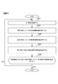
- FIG. 6 is a flowchart showing the flow of the image processing method according to the first embodiment.
- FIG. 7 is a flowchart showing the flow of the first image processing according to the first embodiment.
- FIG. 8 is a flowchart showing the flow of the second image processing according to the first embodiment.
- FIG. 1 is a conceptual diagram showing the configuration of the image processing apparatus of the first embodiment.
- FIG. 2 is a conceptual diagram showing a configuration of a data processing unit according to the first embodiment.
- FIG. 3 is a conceptual diagram showing a captured image according to the
- FIG. 9 is a conceptual diagram showing the configuration of the data processing unit according to the second modification.
- FIG. 10 is a conceptual diagram for explaining the first image processing according to the second modification.
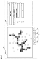
- FIG. 11 is a conceptual diagram showing the linear portion of the captured image and the position of the one-dimensional filter when the angles of the one-dimensional filter are 0 °, 30 °, 60 °, 90 °, 120 ° and 150 °. is there.
- FIG. 12 is a graph showing the angle of the one-dimensional filter and the average value of the pixel values of the plurality of pixels corresponding to the filter.
- FIG. 13 is a graph showing the angle of the one-dimensional filter and the average value of the pixel values of the plurality of pixels corresponding to the filter.
- FIG. 14 is a flowchart showing the flow of the image processing method according to the second modification.
- FIG. 15 is a conceptual diagram for explaining the setting of the range in which the first pixel is selected.
- FIG. 16 is a conceptual diagram showing an example of a display screen for displaying a highlighted image.
- FIG. 17 is a conceptual diagram showing an example of a display screen for setting parameters.
- FIG. 18 is a flowchart showing the flow of the image processing method according to the modified example 7.
- FIG. 19 is a conceptual diagram showing an example of a display screen according to the modified example 7.
- FIG. 20 is a conceptual diagram showing an example of a display screen according to the modified example 7.
- FIG. 21 is a conceptual diagram showing an example of a display screen according to the modified example 7.
- FIG. 22 is a conceptual diagram showing an example of a display screen according to the modified example 8.
- FIG. 23 is a conceptual diagram for explaining the provision of the program.
- FIG. 1 is a conceptual diagram showing the configuration of the image processing apparatus of the present embodiment.
- the image processing device 1 includes a culture unit 100 and an information processing unit 40.
- the culture unit 100 includes a culture chamber (culture chamber) 10, an observation sample table (stage) 11, a drive unit 12, and an imaging unit 20.
- the information processing unit 40 includes an input unit 41, a communication unit 42, a storage unit 43, an output unit 44, and a control unit 50.
- the control unit 50 includes a data processing unit 51, an output control unit 52, and a device control unit 53.
- the image processing device 1 is configured as a culture device, and is configured such that captured image data, which is image data obtained by imaging a sample (eg, a cell) in the culture unit 100, is input to the data processing unit 51 and processed. ing.
- image processing is performed from the captured image corresponding to the captured image data to emphasize a linear portion including straight lines, curves, polygonal lines, intersections, and the like.
- “emphasizing” means making it easier to distinguish the linear part from other parts (eg, the background part, the part other than the linear part) by the pixel value, and the brightness of the linear part is increased.
- the cell Ce is a nerve cell, and an example of emphasizing the portion corresponding to the neurite Nr as a linear portion will be described.
- the linear portion as described above is included, the object to be emphasized is Not limited to this example, it can be any element (eg, other cells, other than cells) that constitutes an image.
- the image processing may be performed on an image other than the captured image, such as a drawn image.
- the culture unit 100 includes a culture chamber 10 for culturing the cells Ce, and the imaging unit 20 takes an image of the cells Ce cultured in the culture chamber 10.
- the culture chamber 10 stores the culture container C in which the cells Ce are cultured.
- the culture vessel C is, for example, a well plate or a dish.
- a temperature controller eg, heater
- a temperature sensor not shown
- the inside of the culture chamber 10 is controlled so that the cells Ce are cultured in a preset environment, such as being maintained at a preset temperature by the temperature controller and the temperature sensor.
- the drive unit 12 includes an actuator, moves the culture vessel C at a predetermined time, and places it on the observation sample table 11 inside the culture chamber 10.
- the driving unit 12 places the imaging unit 20 or the observation sample table 11 or the like at an appropriate position in the optical axis direction (eg, so that the cell Ce is arranged on the focal plane of the imaging unit 20 for imaging the cell Ce). , Observation position).
- the image pickup unit 20 includes an image pickup device including an image pickup element such as CMOS or CCD, and images a cell Ce, particularly a neurite Nr of the cell Ce.
- an image pickup element such as CMOS or CCD
- the pixel corresponding to the neurite Nr is distinguished from other parts with desired accuracy by the brightness value of the pixel or a plurality of pixels around the pixel. If it can be done, it is not particularly limited.
- a fluorescence observation method, a phase difference observation method, or the like can be used as a method of imaging by the imaging unit 20 .
- the imaging unit 20 acquires a fluorescence image of the sample, and the fluorescence image is used for image analysis described later.
- the phase difference observation method the imaging unit 20 acquires the phase difference image of the sample.
- the phase difference image is used for image analysis described later.
- a fluorescent protein such as green fluorescent protein (GFP) is expressed in the cell Ce by gene transfer, or a protein localized in the neuroprojection Nr is fused with the fluorescent protein. Fluorescent staining can be performed by expressing the protein. If there is no problem in using cell Ce after imaging (eg, culture, passage, pickup), other labeling methods such as immunostaining may be performed.
- GFP green fluorescent protein
- the pixel signal obtained by imaging the cell Ce by the imaging unit 20 is converted into a digital signal and input to the information processing unit 40 as captured image data in which the pixels and the brightness value are associated with each other (arrow A1 in FIG. 1). ), Stored in the storage unit 43.
- the information processing unit 40 serves as an interface with a user of the image processing device 1 (hereinafter, simply referred to as a “user”), and also performs processing such as communication, storage, and calculation related to various data.
- the information processing unit 40 may be configured as an information processing device physically separated from the culture unit 100. Further, at least a part of the data used by the image processing device 1 may be stored in a remote server or the like connected by a network.
- the input unit 41 includes an input device such as a mouse, a keyboard, various buttons, and a touch panel.
- the input unit 41 receives from the user data and the like necessary for imaging by the culture unit 100 and data processing by the data processing unit 51.
- the communication unit 42 is provided with a communication device capable of communicating by wireless or wired connection such as the Internet, and appropriately transmits and receives data related to control and processing in the image processing device 1.
- the storage unit 43 includes a non-volatile storage medium, and stores a program for causing the control unit 50 to perform processing, image data related to the processing of the data processing unit 51, and the like.
- the output unit 44 includes a display device such as a liquid crystal monitor, and outputs an image or the like showing the information obtained by the processing of the data processing unit 51.
- the control unit 50 is composed of a processing device such as a CPU, functions as a main body of an operation for controlling the image processing device 1, and performs various processes by executing a program mounted on the storage unit 43.
- the data processing unit 51 of the control unit 50 acquires and processes the captured image data input from the imaging unit 20 to generate an image in which the linear portion of the captured image is emphasized.
- this image is referred to as an emphasized image.
- FIG. 2 is a conceptual diagram showing the configuration of the data processing unit 51.
- the data processing unit 51 includes a first image processing unit 61, a second image processing unit 62, a first removal unit 64, and a binarization unit 65.
- the first image processing unit 61 includes a first pixel group setting unit 611, a first calculation unit 612, and a first pixel value setting unit 613.
- the second image processing unit 62 includes a second pixel group setting unit 621, a second calculation unit and 622, and a second pixel value setting unit 623.
- the first pixel group setting unit 611 and the second pixel group setting unit 621 constitute a setting unit.
- the first image processing unit 611 of the data processing unit 51 performs image processing on the captured image data corresponding to the captured image and generates the first emphasized image data corresponding to the first emphasized image.
- this image processing by the first image processing unit 611 is referred to as a first image processing.
- the first emphasized image is an emphasized image in which a linear portion (eg, neurite Nr) in the captured image is emphasized by the first image processing.
- the first image processing unit 611 sets the pixel value of the first emphasized image corresponding to each pixel in the captured image.
- the pixel to be processed by the first image processing unit 61 in the captured image is referred to as a first pixel
- the pixel in the first emphasized image corresponding to the first pixel is referred to as a second pixel.
- "corresponding" between the first pixel and the second pixel means that these pixels indicate the brightness due to the light from the same position of the subject in the captured image, and the position has the desired accuracy of analysis. If obtained, a certain deviation is allowed.
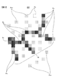
- FIG. 3 is a conceptual diagram showing an example of a captured image.
- the captured image G1 is composed of a plurality of pixels Px.
- the darker the hatched portion the higher the brightness of the pixel.
- the cell body So and the neurite Nr are shown as high-luminance portions.
- noise pixels Pxn which are pixels having brightness due to noise or the like in imaging, are also scattered in the captured image G1.
- the pixel signal corresponding to the linear portion such as the neurite Nr is weak, so that imaging cannot be performed with sufficient accuracy. In particular, this tendency can be seen in fluorescence microscopes that are often used for imaging cells and the like.
- the method of expressing the image in the captured image data is not particularly limited. For example, the larger the pixel value, the higher the brightness or saturation, or the smaller the pixel value, the higher the brightness or saturation.
- the nerve cells are evaluated by measuring numerical values such as the length (or width) of the neurite Nr and the number of branches.
- the image processing apparatus 1 of the present embodiment makes it easy to appropriately extract the neurite Nr by generating an image that emphasizes a linear portion in the captured image.
- the image processing apparatus 1 of the present embodiment can be used for various purposes such as using, extracting, or analyzing a linear portion in an image.
- a portion corresponding to the cell body So can be detected in advance from the captured image, and the portion can be masked to perform the following first image processing and the like.
- the cell body So can be appropriately detected by erasing the details of the captured image by an opening process, a closing process, or the like.
- the first pixel group setting unit 611 of the first image processing unit 61 sets a plurality of first pixel groups corresponding to the first pixel of the captured image G1.
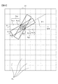
- FIG. 4 is a conceptual diagram for explaining the first image processing.
- the first pixel group setting unit 611 selects the first pixel Px1 from the pixels Px included in the captured image G1.
- the first pixel group setting unit 611 is the first pixel from the pixels included in the region (hereinafter, referred to as a target region) in which the first pixel Px1 is selected in the captured image G1 set in advance by the first image processing unit 61. Select and set Px1.
- the target area may be the entire captured image, but for example, when the pixel at the edge of the captured image G1 is the first pixel Px1, there may be no pixel corresponding to the one-dimensional filter described later. Therefore, in this case, it is preferable to appropriately replenish the virtual pixels around the captured image G1 so that the image processing described later is performed with desired accuracy.
- the target area should be set to a portion excluding the edge portion of about half the length of the one-dimensional filter from the captured image G1 so that there is no case where there is no pixel corresponding to the one-dimensional filter described later. Can be done.
- the first pixel group setting unit 611 sets a pixel group including the first pixel Px1 and arranged along a plurality of directions forming a predetermined angle with respect to the reference direction as the first pixel group Pg1.
- This predetermined angle is hereinafter referred to as a first angle ⁇ 1.
- the reference direction is the left-right direction of the captured image G1 (see arrow A10), but the reference direction is not particularly limited and may be any direction.
- FIG. 4 shows a plurality of pixels Px11, Px12, Px1, Px13 and Px14 included in the first pixel group Pg1 when the first angle ⁇ 1 is 0 °.
- the first pixel group Pg1 includes a plurality of pixels arranged in one direction and adjacent to each other in this way.
- the first angle ⁇ 1 is 45 ° and 90 °
- the first pixel group setting unit 611 sets a plurality of pixels arranged diagonally and vertically in the captured image G1 and adjacent to each other as the first pixel group Pg1. Can be done.
- the partial regions of the captured image G1 corresponding to the first pixel group Pg1 when the first angles ⁇ 1 are 0 °, 30 °, and 60 ° are schematically shown by the one-dimensional filters F1, F11, and F12, respectively. It was.
- the first pixel group Pg1 corresponding to the one-dimensional filters F11 and F12 the pixel overlapping with these one-dimensional filters and the pixel through which the straight line corresponding to these one-dimensional filters passes are included in the first pixel group Pg1. Can be done. However, since the pixels set in this way do not line up in a straight line, the accuracy drops a little.
- the first pixel group setting unit 611 centers the pixel corresponding to the first pixel in the image obtained by rotating the captured image G1 in the direction forming the first angle ⁇ 1 with respect to the reference direction. It is preferable to set a plurality of pixels arranged along a predetermined direction as the first pixel group Pg1.
- This predetermined direction is not particularly limited, and may be any direction such as a reference direction.
- the first pixel group setting unit 611 rotates the captured image G1 clockwise by ⁇ 1 while fixing the one-dimensional filter F1, and the vertical 1 within the range of the one-dimensional filter F1 in the obtained image.
- ⁇ A pixel having 5 pixels in the horizontal direction is set as the first pixel group Pg1.
- the first pixel group Pg1 corresponding to the one-dimensional filter F11 in the captured image G1 before rotation can be set more precisely than in the case where the first pixel group Pg1 is set by rotating the one-dimensional filter.
- the first pixel group setting unit 611 sets the first pixel group Pg1 for each of the plurality of first angles ⁇ 1.
- a plurality of first angles ⁇ 1 are set for each predetermined angle selected from a range of, for example, 1 ° to 45 °.
- the first pixel group setting unit 611 can set a plurality of first angles ⁇ 1 from 0 ° to 179 ° for each 1 °, and can set the first pixel group Pg1 for each first angle ⁇ 1.
- the number of pixels constituting the first pixel group Pg1 is not particularly limited as long as it is 2 or more.
- the number of the pixels can be set based on the curvature or radius of curvature of the linear portion in the captured image G1.
- the first pixel group Pg1 may be a pixel group composed of a plurality of columns such as a pixel block of 2 pixels ⁇ 5 pixels. In this case, it is preferable that the number of pixels arranged in one direction exceeds twice the number of pixels arranged in the other direction.
- the first calculation unit 612 of the first image processing unit 61 calculates the first candidate pixel value based on the pixel values of the pixels included in the first pixel group Pg1.
- the first candidate pixel value is a value that is a candidate for a pixel value set in the second pixel corresponding to the first pixel Px1 in the first emphasized image.
- the pixel value set for the second pixel is selected from a plurality of first candidate pixel values.
- the first calculation unit 612 calculates the average value of the pixel values of the pixels included in the first pixel group Pg1 and uses it as the first candidate pixel value. For example, the first calculation unit 612 calculates the arithmetic mean of the pixels of the pixels Px11, Px12, Px1, Px13 and Px14 corresponding to the one-dimensional filter F1, and the first of the first pixel group Pg1 corresponding to the one-dimensional filter F1. Use as a candidate pixel value. The first calculation unit 612 calculates the first candidate pixel value for each first pixel group Pg1 set by the first pixel group setting unit 611.
- the first calculation unit 612 calculates the first candidate pixel value for the first pixel group Pg1 corresponding to each of the plurality of first angles ⁇ 1.
- the first calculation unit 612 may calculate the average value of the pixel values of the pixels included in the first pixel group Pg1 as the first candidate pixel value by an average other than the arithmetic mean such as the geometric mean.
- the first calculation unit 612 sets the sum of the pixel values of the pixels included in the first pixel group Pg1 and the value adjusted by appropriate standardization or the like according to the numerical range in which the sum can be set as the pixel value. It can be set as the first candidate pixel value.
- the first candidate pixel value can be set based on the overall size of the pixel values of the pixels included in the first pixel group Pg1 as in the sum or average, it is set by the first calculation unit 612.
- the calculation method of the first candidate pixel value is not particularly limited.
- the first pixel value setting unit 613 of the first image processing unit 61 is a second pixel in the first emphasized image corresponding to the first pixel Px1 from a plurality of first candidate pixel values calculated for the first pixel Px1. Set the pixel value.
- the first pixel value setting unit 613 can set the largest value among the plurality of first candidate pixel values for the first pixel Px1 to the pixel value of the corresponding second pixel. This means that in the first image processing, among the one-dimensional filters F, F11, and F12 in a plurality of directions, the pixel value by the one-dimensional filter corresponding to the direction in which the pixel having the highest pixel value is arranged is the first emphasized image. Will be reflected in. As a result, when the higher the pixel value, the higher the possibility that the pixel corresponds to a linear portion such as a neurite Nr, smoothing can be performed and the linear portion can be emphasized.
- the first pixel value setting unit 613 can set the smallest value among the plurality of first candidate pixel values for the first pixel Px1 to the pixel value of the corresponding second pixel.
- the pixel value of the second pixel may be set in the range of 0.8 times to 1.2 times, preferably 0.9 times to 1.1 times, the largest value or the smallest value. .. Even in such a case, the linear portion can be emphasized with a certain degree of accuracy.
- the captured image G1 The first image processing is performed with a pixel different from the first pixel Px1 in the target region as the first pixel Px1.
- the first image processing unit 61 performs the first image processing on each pixel included in the target area.
- the first pixel group setting unit 611 and the first calculation unit 612 fix the first angle ⁇ 1 and use a one-dimensional filter in the direction corresponding to the first angle ⁇ 1 for each first pixel Px1 in the target area.
- the first candidate pixel value may be calculated.
- the first pixel group setting unit 611 and the first calculation unit 612 change the first angle ⁇ 1 and fix it again, and similarly calculate the first candidate pixel value of each first pixel Px1.
- the first pixel value setting unit 613 determines the pixel value of the second pixel corresponding to each first pixel Px1. Can be calculated. As described above, if the pixel value of the corresponding second pixel can be calculated for each pixel Px in the setting area, the order of calculation and the like are not particularly limited.
- the second image processing unit 62 of the data processing unit 51 performs image processing on the captured image data corresponding to the captured image G1 to generate the two-dimensional smoothed image data corresponding to the two-dimensional smoothed image.
- this image processing by the second image processing unit 62 is referred to as a second image processing.
- the two-dimensional smoothed image is an image obtained by smoothing the captured image G1 with a two-dimensional filter corresponding to pixels arranged along at least two directions. In the two-dimensional filter, it is preferable that the number of pixels arranged in one direction is twice or less the number of pixels arranged in the other direction.
- the second image processing unit 62 sets the pixel value of the two-dimensional smoothed image corresponding to each pixel in the captured image G1.
- the pixel in the two-dimensional smoothed image corresponding to the first pixel Px1 in the captured image G1 is referred to as a third pixel.
- the second pixel group setting unit 621 of the second image processing unit 62 sets a plurality of second pixel groups corresponding to the first pixel Px1 of the captured image G1.
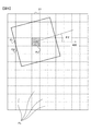
- FIG. 5 is a conceptual diagram for explaining the second image processing.
- the second pixel group setting unit 621 selects the first pixel Px1 from the pixels Px included in the captured image G1.
- the second pixel group setting unit 621 selects and sets the first pixel Px1 from the pixels included in the target area.
- the second pixel group setting unit 621 includes a first pixel Px1 and moves a two-dimensional filter F2 including rotation of a predetermined angle with respect to a reference direction to obtain a pixel group corresponding to the two-dimensional filter. It is set as a two-pixel group Pg2.
- the second pixel group Pg2 is a pixel group arranged along at least two directions in which the pixel groups arranged along at least two directions are rotated by a predetermined angle in the at least two directions. ..
- the second pixel group setting unit 621 sets a plurality of second pixel groups Pg2 for each of the plurality of predetermined angles. This predetermined angle is hereinafter referred to as a second angle ⁇ 2.
- the reference direction is the left-right direction of the captured image G1 (see arrow A20), but the reference direction is not particularly limited.
- the reference direction may be any direction and may be different from the reference direction in the above-described first image processing.
- the two-dimensional filter F2 corresponds to a square pixel block of 5 vertical pixels ⁇ 5 horizontal pixels
- the second pixel group Pg2 corresponding to the two-dimensional filter F2 is the 5 ⁇ centered on the first pixel Px1. Includes 5 pixels.
- the shape of the two-dimensional filter F2 corresponding to the second pixel group Pg2 is not particularly limited.
- the second pixel group Pg2 preferably includes a plurality of pixels adjacent to each other.
- the partial regions of the captured image G1 corresponding to the second pixel group Pg2 when the second angle ⁇ 2 is 0 ° and about 20 ° are schematically shown by the two-dimensional filters F2 and F21, respectively.
- the pixels and the like overlapping with the two-dimensional filter F21 can be included in the second pixel group Pg2.
- the pixels set in this way have a slightly lower accuracy because the shape of the pixel block corresponding to the second pixel group Pg2 varies.
- the second pixel group setting unit 621 centers on the pixel corresponding to the first pixel in the image obtained by rotating the captured image G1 in the direction forming the second angle ⁇ 2 with respect to the reference direction. It is preferable to set a plurality of pixels arranged along at least two directions as the second pixel group Pg2.
- the second pixel group setting unit 621 rotates the captured image G1 clockwise by ⁇ 2 while fixing the two-dimensional filter F2, and the vertical 5 within the range of the two-dimensional filter F2 in the obtained image.
- ⁇ A pixel of 5 pixels in the horizontal direction is set as the second pixel group Pg2.
- the second pixel group Pg2 corresponding to the two-dimensional filter F21 in the captured image G1 before rotation can be set more precisely than in the case where the second pixel group Pg2 is set by rotating the two-dimensional filter F2. ..
- the second pixel group setting unit 621 sets the second pixel group Pg2 for each of the plurality of second angles ⁇ 2.
- a plurality of the plurality of second angles ⁇ 2 are set for each predetermined angle selected from a range of, for example, 1 ° to 45 °.
- the second pixel group setting unit 621 can set a plurality of second angles ⁇ 2 from 0 ° to 179 ° for each 1 °, and can set the second pixel group Pg2 for each second angle ⁇ 2.
- the second calculation unit 622 of the second image processing unit 62 calculates the second candidate pixel value based on the pixel value of the pixel included in the second pixel group Pg2.
- the second candidate pixel value is a value that is a candidate for a pixel value set in the third pixel corresponding to the first pixel Px1 in the second emphasized image.
- the pixel value set for the third pixel is selected from a plurality of second candidate pixel values.
- the second calculation unit 622 calculates the average value of the pixel values of the pixels included in the second pixel group Pg2 and uses it as the second candidate pixel value. For example, the second calculation unit 612 calculates the arithmetic mean of the pixel values of the 5 ⁇ 5 pixels corresponding to the two-dimensional filter F2, and sets the second candidate pixel value of the second pixel group Pg2 corresponding to the two-dimensional filter F2. To do. The second calculation unit 622 calculates the second candidate pixel value for each second pixel group Pg2 set by the second pixel group setting unit 621. The second calculation unit 622 calculates the second candidate pixel value for the second pixel group Pg2 corresponding to each of the plurality of second angles ⁇ 2.
- the second calculation unit 612 may calculate the average value of the pixel values of the pixels included in the second pixel group Pg2 as the second candidate pixel value by an average other than the arithmetic mean such as the geometric mean.
- the second calculation unit 622 sets the sum of the pixel values of the pixels included in the second pixel group Pg2 and the value adjusted by appropriate standardization or the like according to the numerical range in which the sum can be set as the pixel value. It can be set as the second candidate pixel value. If the second candidate pixel value can be set based on the overall size of the pixel values of the pixels included in the second pixel group Pg2 as in the sum or average, it is set by the second calculation unit 622.
- the calculation method of the second candidate pixel value is not particularly limited.
- the second pixel value setting unit 623 of the second image processing unit 62 is a third pixel in a two-dimensional smoothed image corresponding to the first pixel Px1 from a plurality of second candidate pixel values calculated for the first pixel Px1. Set the pixel value of.
- the second pixel value setting unit 623 can set the largest value among the plurality of second candidate pixel values for the first pixel Px1 to the pixel value of the corresponding third pixel. This means that in the second image processing, among the two-dimensional filters F2 and F21 corresponding to the plurality of second angles ⁇ 2, the pixel value by the two-dimensional filter including the pixel having the highest pixel value as a whole is two-dimensionally smoothed. It will be reflected in the image. As a result, when the higher the pixel value, the higher the brightness, smoothing that is not biased in a specific direction can be effectively performed.
- the second pixel value setting unit 623 can set the smallest value among the plurality of second candidate pixel values for the first pixel Px1 to the pixel value of the corresponding third pixel.
- the pixel value of the third pixel may be set in the range of 0.8 times to 1.2 times, preferably 0.9 times to 1.1 times, the largest value or the smallest value. .. Even in such a case, smoothing that is not biased in a specific direction can be performed with a certain degree of accuracy.
- the captured image G1 The second image processing is performed with a pixel different from the first pixel Px1 in the target region as the first pixel Px1.
- the second image processing unit 61 performs the second image processing on each pixel included in the target area.
- the order of calculation is not particularly limited as long as the pixel value of the corresponding third pixel can be calculated for each pixel Px in the setting area.
- the first removing unit 64 removes at least a part of the non-linear portion in the first emphasized image based on the two-dimensional smoothed image data, and the second emphasis corresponds to the second emphasized image.
- “removal” refers to removing a component of a pixel value that does not contribute to showing a non-linear portion in the first emphasized image.
- the first removing unit 64 generates an image in which the absolute value of the difference obtained by subtracting the pixel value of the two-dimensional smoothed image from the pixel value of the first emphasized image is the pixel value as the second emphasized image. be able to.
- a second emphasized image which is an enhanced image in which the linear portion is further emphasized by removing the spread of brightness and noise having low direction dependence from the first emphasized image, can be obtained.
- the binarization unit 65 binarizes the pixel values of the second emphasized image by a plurality of threshold values appropriately different for each portion based on the pixel values of the pixels included in each portion of the second emphasized image. I do.
- the binarization unit 65 divides the second emphasized image into a plurality of regions. These areas are called divided areas.
- the binarization unit 65 calculates, for each divided region, the average value of the pixel values of the pixels included in the divided region based on the arithmetic mean and the like, and the standard deviation of the pixel values.
- the binarization threshold by the binarization unit 65 is called the binarization threshold Th.
- the binarization unit 65 stores the detection result image data obtained by performing the above binarization of the second emphasized image data in the storage unit 43 or the like.
- the binarization unit 65 may store the data obtained by performing the above binarization of the first emphasized image data in the storage unit 43 or the like as the detection result image data. In this case, it is not necessary to perform the above-mentioned second image processing and the processing of the first removing unit 64.
- the linear portion can be emphasized with a desired accuracy by the first image processing without performing the second image processing and the processing by the first removing unit 64.
- the data processing unit 51 can appropriately perform image processing such as level correction for removing a relatively dark portion in the image before the binarization processing by the binarization unit 65.
- the data processing unit 51 can detect the neurite Nr in the detection result image, detect the crossover, or analyze which cell the fragment of the linear portion is connected to as appropriate. Further, the data processing unit 51 analyzes the length of the neurite Nr and the like, and can evaluate the state of the cultured or cultured cell Ce based on the data obtained by this analysis. ..
- the output control unit 52 generates an output image to be output to the output unit 44 based on the detection result image data, and causes the output unit 44 to output the output image.
- the output control unit 52 displays the detection result image on the display monitor of the output unit 44.
- the device control unit 53 of the control unit 50 controls each unit of the culture unit 100 based on the input from the input unit 41 or the like (arrow A2).
- the device control unit 53 executes control related to cell culture (eg, control of the culture chamber 10 that controls temperature or humidity, control of the drive unit 12), or causes the image pickup unit 20 to perform imaging.
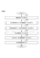
- FIG. 6 is a flowchart showing the flow of the image processing method according to the present embodiment.
- the data processing unit 51 acquires the captured image data obtained by the imaging of the imaging unit 20.
- step S103 is started.
- step S103 the first image processing unit 61 performs the first image processing on the captured image data to generate the first emphasized image data.
- step S105 is started.
- step S105 the second image processing unit 62 performs the second image processing on the captured image data to generate the two-dimensional smoothed image data.
- step S107 the first removing unit 64 generates the second emphasized image data from the first emphasized image data and the two-dimensional smoothed image data.
- step S109 is started.
- step S109 the binarization unit 65 binarizes the second emphasized image data and generates the detection result image data.
- step S111 is started.
- step S111 the output control unit 52 displays the detection result image on the output unit 44.
- FIG. 7 is a flowchart showing the flow of step S103 (first image processing) in the flowchart of FIG.
- step S201 is started.
- the first pixel group setting unit 611 selects the first pixel Px1 in which the pixel value of the corresponding second pixel is not set from the target area.
- step S203 is started.
- step S203 the first pixel group setting unit 611 sets the first pixel group Pg1 included in the one-dimensional filter F1 extending in the reference direction, and the first calculation unit 612 sets the first candidate pixel value in the reference direction. calculate.
- step S205 the first pixel group setting unit 611 rotates the one-dimensional filter or generates data obtained by rotating the captured image, sets the first pixel group Pg1 for each first angle ⁇ 1, and sets the first pixel group Pg1.
- the calculation unit 612 calculates the first candidate pixel value for each first angle ⁇ 1.
- step S207 is started.
- step S207 the first pixel value setting unit 613 sets the pixel value of the second pixel corresponding to the first pixel Px1 from the first candidate pixel value for the first pixel Px1.
- step S209 is started.
- the order of steps S203, S205 and S207 may be changed as appropriate.
- step S209 the data processing unit 51 determines whether or not the pixel value of the second pixel corresponding to the first pixel Px1 is set for all the first pixel Px1 in the target area.
- the data processing unit 51 affirms step S209 and starts step S105.
- the data processing unit 51 negatively determines step S209 and starts step S201.
- FIG. 8 is a flowchart showing the flow of step S105 (second image processing) in the flowchart of FIG.
- step S301 is started.
- the second pixel group setting unit 621 selects the first pixel Px1 in which the pixel value of the corresponding third pixel is not set from the target area.
- step S303 is started.
- step S303 the second pixel group setting unit 621 sets the second pixel group Pg2 included in the two-dimensional filter F2 for the reference direction, and the second calculation unit 622 sets the second candidate pixel value for the reference direction. calculate.
- step S305 the second pixel group setting unit 621 rotates the two-dimensional filter or generates data obtained by rotating the captured image, sets the second pixel group Pg2 for each second angle ⁇ 2, and sets the second pixel group Pg2.
- the calculation unit 622 calculates the second candidate pixel value for each second angle ⁇ 2.
- step S307 is started.
- step S307 the second pixel value setting unit 623 sets the pixel value of the third pixel corresponding to the first pixel Px1 from the second candidate pixel value for the first pixel Px1.
- step S309 is started.
- the order of steps S303, S305 and S307 may be changed as appropriate.
- step S309 the data processing unit 51 determines whether or not the pixel value of the third pixel corresponding to the first pixel Px1 is set for all the first pixel Px1 in the target area.
- the data processing unit 51 affirms step S309 and starts step S107.
- the data processing unit 51 negatively determines step S309 and starts step S301.
- the image processing device 1 of the present embodiment is positioned at a position corresponding to the first pixel Px1 of the captured image G1 in the enhanced image (second image) obtained by image processing the captured image (first image) G1.
- a first image processing unit 61 for setting the pixel value of the second pixel of the emphasized image is provided, and the first image processing unit 61 is a plurality of first pixel groups Pg1 set corresponding to the first pixel Px1. Therefore, the captured image G1 is arranged along a plurality of directions (first angle ⁇ 1) different from each other with respect to a predetermined direction (reference direction of the image), or the captured image G1 is predetermined.
- the first pixel group setting unit 611, and the first calculation unit 612 that calculates a plurality of first candidate pixel values based on the size of the pixel values of the pixels included in each of the plurality of first pixel groups Pg1. It includes a first pixel value setting unit 613 that sets the pixel value of the second pixel of the emphasized image based on the plurality of first candidate pixel values. This makes it possible to effectively emphasize the linear portion of the cell in the image.
- the first calculation unit 612 has a plurality of first candidate pixels based on the sum or average of the pixel values of the pixels included in each of the plurality of first pixel groups Pg1. The value can be calculated. This makes it possible to detect the direction in which pixels with high pixel values are lined up and more effectively emphasize the linear portion in the image.
- the first calculation unit 612 calculates the first candidate pixel value for the first pixel group Pg1 by using the smoothing filters F1, F11, and F12. Thereby, the linear portion based on the length of the smoothing filter can be detected, and the linear portion in the image can be emphasized more effectively.
- the one-dimensional filters F1, F11, and F12 are one-dimensional smoothing filters.
- the linear portion can be detected by the shape of the one-dimensional filter (eg, the shape including the length and the thickness), and the linear portion in the image can be emphasized more effectively.
- the first pixel setting unit 611 for setting the first pixel Px1 from the pixels constituting the captured image G1 is provided, and the first pixel value setting unit 611 has a plurality of first pixels. 1. Set a value 0.8 to 1.2 times the largest value of the candidate pixel values, or 0.8 to 1.2 times the smallest value, as the pixel value of the second pixel. Can be done. This makes it possible to detect the direction in which pixels with high or low pixel values are lined up and more effectively emphasize the linear portion in the image.
- the second pixel group setting unit 623 is a two-dimensional filter at a plurality of angles (second angle ⁇ 2) different from a predetermined direction (reference direction) in the captured image G1. At least in each of the captured images G1 arranged along at least two directions obtained by rotating at least two directions in which the pixels are arranged in the above, or rotated at a plurality of different angles (second angle ⁇ 2). A plurality of second pixel groups Pg2 arranged along the two directions are set, and the second image processing unit 62 is based on the sum or average of the pixel values of the pixels included in each of the plurality of second pixel groups Pg1.
- a second calculation unit 622 for calculating a plurality of second candidate pixel values is provided, and the second pixel value calculation unit 623 sets the pixel value of the third pixel based on the plurality of second candidate pixel values.
- the image processing apparatus 1 of the present embodiment includes a first removing unit 64 that removes at least a part of a non-linear portion in the enhanced image based on the two-dimensional smoothed image.
- a first removing unit 64 that removes at least a part of a non-linear portion in the enhanced image based on the two-dimensional smoothed image.
- the image processing device 1 of the present embodiment binarizes the pixel values of the emphasized image by a plurality of different binarization thresholds Th based on the pixel values of the pixels included in each part of the emphasized image.
- the binarization unit 64 to be performed is provided. As a result, whether or not each pixel in the image corresponds to a linear portion can be easily indicated by binarization and can be easily analyzed.
- the captured image G1 is an image of the neurite Nr. This makes it possible to effectively emphasize the portion of the image corresponding to the neurite Nr. In addition, the length of the neurite Nr and the like can be analyzed more accurately by using the image in which the neurite Nr is emphasized.
- the image pickup apparatus includes the above-mentioned image processing apparatus 1 and an image pickup unit 20 that images a cell or the like including a linear portion. As a result, the linear portion in the captured image can be effectively emphasized.
- the above-mentioned image processing device 1 which is the culture device according to the present embodiment includes a culture unit 100 for culturing cells. This makes it possible to effectively emphasize the linear portion in the image of the cells Ce cultured in the undifferentiated state or the differentiated state.
- the image processing method in the emphasized image (second image) obtained by image processing the captured image (first image) G1, the position corresponding to the first pixel Px1 of the captured image G1 A certain pixel value of the second pixel of the captured image G1 is set, and the pixel value of the second pixel is set by a plurality of first pixel groups Pg1 set corresponding to the first pixel Px1.
- the captured image G1 is arranged along a plurality of different angles (first angle ⁇ 1) with respect to a predetermined direction (reference direction), or the captured image G1 is arranged at a plurality of different angles (first angle ⁇ 1).
- the second image processing unit 62 does not perform the process of moving and rotating the two-dimensional filter or the captured image G1, and is calculated from the pixels included in one two-dimensional filter.
- the second candidate pixel value may be the pixel value of the third pixel. Even in such a case, if the two-dimensional filter originally has a shape with a small bias in a specific direction, smoothing that is not biased in the specific direction can be performed with a certain degree of accuracy.
- the image processing device 1 of this modified example sets the pixel value of the third pixel at the position corresponding to the first pixel Px1 in the two-dimensional smoothed image obtained by image processing the captured image G1.
- the second image processing unit 62 includes a unit 62, and the second image processing unit 62 is set corresponding to the first pixel Px1 and sets a second pixel group Pg2 including pixels arranged along at least two directions.
- a unit 621 and a second pixel value setting unit 623 that sets the pixel value of the third pixel based on the sum or average of the pixel values of the pixels included in the second pixel group Pg2.
- the image processing apparatus 1 may be configured to generate information as to whether or not the first pixel Px1 in the captured image G1 corresponds to the linear portion by using a one-dimensional filter.
- this information will be referred to as pixel correspondence information with respect to the linear portion (eg, neurite Nr).
- FIG. 9 is a conceptual diagram showing the configuration of the data processing unit 51a in the image processing device of this modified example.
- the data processing unit 51a is different from the above-mentioned data processing unit 51 in that the data processing unit 51a includes the pixel information processing unit 63.
- the pixel information processing unit 63 includes a third pixel group setting unit 631, an information generation unit 632, and a processing control unit 633.
- the pixel information processing unit 63 acquires information from the captured image data using a one-dimensional filter and processes the information.
- the third pixel group setting unit 631 sets a plurality of third pixel groups Pg3 corresponding to the first pixel Px1 in the captured image G1. Similar to the setting of the plurality of first pixel groups Pg1 by the first pixel group setting unit 631 described above, the third pixel group setting unit 631 uses a plurality of one-dimensional filters F1, F11, F12 corresponding to a plurality of angles. The third pixel group Pg3 is set.
- FIG. 10 is a conceptual diagram for explaining the third pixel group Pg3.
- the third pixel group setting unit 631 selects the first pixel Px1 from the pixels Px included in the captured image G1.
- the third pixel group setting unit 631 selects and sets the first pixel Px1 from the pixels included in the target area.
- the third pixel group setting unit 631 sets a pixel group including the first pixel Px1 and arranged along a plurality of directions forming a predetermined angle with respect to the reference direction as the third pixel group Pg3.
- This predetermined angle is hereinafter referred to as a third angle ⁇ 3.
- the reference direction is the left-right direction of the captured image G1 (see arrow A30), but the reference direction is not particularly limited and may be any direction.
- a plurality of pixels Px31, Px32, Px1, Px33 and Px34 included in the third pixel group Pg3 when the third angle ⁇ 3 is 0 ° are shown. It is preferable that the third pixel group Pg3 includes a plurality of pixels arranged in one direction and adjacent to each other in this way.
- the third pixel group setting unit 631 corresponds to the first pixel in the image obtained by moving the captured image G1 including rotation in the direction forming the third angle ⁇ 3 with respect to the reference direction. It is preferable to set a plurality of pixels arranged along a predetermined direction centered on the pixels as the third pixel group Pg3. This predetermined direction is not particularly limited, and may be any direction such as a reference direction. As a result, it is possible to set the third pixel group Pg3 more precisely than when the one-dimensional filter F1 is moved including rotation to set the third pixel group Pg3.
- the third pixel group setting unit 631 sets the third pixel group Pg3 for each of the plurality of third angles ⁇ 3.
- a plurality of the plurality of third angles ⁇ 3 are set for each predetermined angle selected from a range of, for example, 1 ° to 45 °.
- the third pixel group setting unit 631 can set a plurality of third angles ⁇ 3 from 0 ° to 179 ° for each 1 °, and can set the third pixel group Pg3 for each third angle ⁇ 3.
- the third pixel group setting unit 631 sets the third pixel group Pg3 for each first pixel Px1 in the target area.
- the information generation unit 632 generates the above-mentioned corresponding information.
- the information generation unit 632 calculates the sum or average of the pixel values, which is a value representing the overall size of the pixel values of the pixels included in each of the plurality of third pixel groups Pg3. As this average, an arithmetic mean or the like can be used as appropriate.
- the sum or average of the calculated pixel values is referred to as a one-dimensional filter value.
- FIG. 11 is a conceptual diagram showing a one-dimensional filter corresponding to the third angle ⁇ 3 and a linear partial LP for a plurality of third angles ⁇ 3.
- FIG. 11 shows a one-dimensional filter F100 when the third angle ⁇ 3 is 0 °, a one-dimensional filter F110 when the third angle ⁇ 3 is 30 °, and a one-dimensional filter F120 when the third angle ⁇ 3 is 60 °.
- a one-dimensional filter F130 when the third angle ⁇ 3 is 90 °, a one-dimensional filter F140 when the third angle ⁇ 3 is 120 °, and a one-dimensional filter F150 when the third angle ⁇ 3 is 150 ° are shown.
- the first pixel Px1 is located on the linear portion LP, it is a pixel corresponding to the linear portion.
- the pixel value of the pixel corresponding to the linear partial LP is the pixel value of the nearby pixel that does not correspond to the linear portion. Is higher than.
- the one-dimensional filter value which is the sum or average value of the pixel values of the pixels corresponding to the one-dimensional filter, becomes the highest.
- the third angles ⁇ 3 are 0 °, 120 °, and 150 °
- the overlap between the one-dimensional filters F100, F140, and F150 and the linear partial LP is small, and the one-dimensional filter value is the other third angle. It is smaller than the case of ⁇ 3.
- the third angle ⁇ 3 is 30 ° or 90 °
- the one-dimensional filter F110 or the one-dimensional filter F130 and the linear partial LP have an overlap of about 3 out of 5 pixels constituting the one-dimensional filter. Therefore, the one-dimensional filter value is larger than when the third angle ⁇ 3 is 0 °, 120 °, or 150 °.
- the third angle ⁇ 3 is 60 °
- the one-dimensional filter F120 and the linear partial LP substantially overlap each other, and in the case shown in FIG. 11, the one-dimensional filter value is the highest.
- the information generation unit 632 generates data in which the third angle ⁇ 3 and the one-dimensional filter value are associated with each other. This data will be referred to as filter value data below.
- the filter value data may be generated by appropriately smoothing or approximating with a curve. As a result, the influence of noise and the like can be reduced and the accuracy can be improved.
- FIG. 12 is a graph showing a one-dimensional filter value for a third angle ⁇ 3 in the first pixel Px1 that can be generated from the filter value data.
- FIG. 12 assumes a case where the one-dimensional filter value as shown in FIG. 11 has an angle dependence.
- the one-dimensional filter value takes a value from Vmin to Vmax, and the one-dimensional filter value becomes the highest when the third angle ⁇ 3 is about 60 °.
- the information generation unit 632 can calculate the peak width of the third angle ⁇ 3 and the peak P1 related to the third angle ⁇ 3, which have the highest one-dimensional filter value.
- the information generation unit 632 can detect the peak based on the difference between Vmax and Vmin, whether or not the S / N ratio or the like is equal to or more than a predetermined value, and the like.
- FIG. 13 is a graph showing a one-dimensional filter value with respect to the third angle ⁇ 3 when there is no remarkable peak.
- the fluctuation of the one-dimensional filter value is smaller than that of the S / N ratio, no peak is detected.
- the characteristics of the subject in the first pixel Px1 can be analyzed by the number of peaks.
- the first pixel Px1 is a portion that does not correspond to a line or an intersection.
- the first pixel Px1 corresponds to the linear portion.
- the number of peaks is two, the first pixel Px1 corresponds to the crossover.
- the information generation unit 632 generates correspondence information as to whether or not the first pixel Px1 corresponds to the linear portion by analyzing such a one-dimensional filter value.
- the information generation unit 632 can binaryly indicate whether or not each pixel in the captured image corresponds to a linear portion, generate correspondence information associated with each pixel, and store it in the storage unit 43 or the like. .. Further, the information generation unit 632 may also generate information on whether or not each pixel in the captured image corresponds to the crossover.
- the information generation unit 632 generates filter value data and correspondence information for each first pixel Px1 in the target region.
- the third pixel group setting unit 631 sets the third pixel group Pg3 by increasing the interval between the plurality of third angles ⁇ 3, and when a peak is detected, the peak is concerned.
- the third pixel group Pg3 can be set by reducing the interval between the third angle ⁇ 3 and its vicinity.
- the information generation unit 632 can accurately calculate the one-dimensional filter value of the peak and its vicinity, and can efficiently analyze the angle dependence of the one-dimensional filter value.
- the processing control unit 633 (FIG. 9) controls the process of setting the first pixel group Pg1 of the first pixel group setting unit 611 based on the correspondence information.
- the processing control unit 633 changes the number of the third angles ⁇ 3 set in the first image processing according to the position of the first pixel Px1 based on the correspondence information.
- the processing control unit 633 can set a smaller number of third angles ⁇ 3 in the pixels that do not correspond to the linear portion than in the pixels that correspond to the linear portion.
- the processing control unit 633 can be set so that the first image processing is not performed on the pixels that do not correspond to the linear portion.
- the processing control unit 633 can set the first image processing so that the first pixel group setting unit 611 selects the first pixel Px1 from the pixels corresponding to the linear portion. In this way, by setting the pixels corresponding to the linear portion to perform the first image processing more precisely, the linear portion in the image can be emphasized more efficiently.
- the processing control unit 633 prevents the first image processing from being performed on the pixel corresponding to the crossover. Etc., the conditions for the first image processing can be set as appropriate based on the information.
- FIG. 14 is a flowchart showing the flow of the image processing method of this modified example.
- the description of step S401 is omitted because it corresponds to step S101 of the flowchart of FIG.
- step S403 is started.
- the information generation unit 632 generates information (correspondence information) as to whether or not the pixels included in the captured image G1 correspond to the linear portion.
- step S405 is started.
- step S405 the processing control unit 633 sets the conditions for the first image processing based on the correspondence information generated in step S403.
- step S407 is started.
- the first image processing unit 61 performs the first image processing based on the conditions set in step S403 to generate the first emphasized image data.
- step S409 is started. Since steps S409 to S415 correspond to steps 105 to S111 in the flowchart of FIG. 6, description thereof will be omitted.
- a plurality of third pixel groups Pg1 set corresponding to the first pixel Px1 in a predetermined direction (reference direction) of the captured image (first image) G1.
- a plurality of images are arranged along a plurality of directions forming a plurality of angles (third angle ⁇ 3) with respect to the image, or a plurality of images obtained by rotating the captured image G1 at a plurality of angles (third angle ⁇ 3).
- the image processing device of this modification includes a processing control unit that controls a process of setting the first pixel group Pg1 of the first pixel group setting unit 611 based on the corresponding information generated by the information generation unit 632. .. As a result, the first image processing can be performed more efficiently by using the generated information.
- the number of a plurality of angles (first angle ⁇ 1) when the first pixel group setting unit 611 sets a plurality of first pixel groups Pg1 is the first pixel Px1.
- the processing control unit 633 can set the above number at each position of the captured image G1 based on the corresponding information. Thereby, the precision of the first image processing can be controlled by the position in the captured image by using the generated information.
- the processing control unit 633 performs a process in which the first pixel group setting unit 611 sets the first pixel group Pg1 at each position of the captured image G1 based on the corresponding information. You can decide whether or not to do it. As a result, the first image processing can be performed even more efficiently by using the generated information.
- the data processing unit 51a may be configured to include a second removing unit that removes at least a part of a non-linear portion in the first emphasized image or the second emphasized image based on the corresponding information.
- the second removing unit sets the pixel value to 0 or the like for the pixel that does not correspond to the linear portion in the correspondence information, and sets the value corresponding to the case where the subject does not exist. As a result, the linear portion in the image can be further emphasized.
- the target area may be set by the user via the input unit 41.
- FIG. 15 is a conceptual diagram showing the target area R1.
- the user can input the range of the target area R1 by, for example, dragging the mouse as the input unit 41 while looking at the display screen of the output unit 44 on which the captured image G1 is displayed.
- the image processing device of this modification includes an input unit 41 for the first image processing unit 61 to input the position or range of the first pixel Px1 to be image processed.
- the subject of the captured image G1 is defined as a cell Ce, and the linear portion to be emphasized is described as a neurite Nr.
- the object to be emphasized is not limited to this example.
- the subject of the captured image G1 is the fundus and the linear portion to be emphasized is the blood vessel in the fundus, and it is even more preferable that the blood vessel of the retina or the choroidal blood vessel is used.
- the captured image G1 is an image of a blood vessel. This makes it possible to effectively emphasize the linear portion in the image of the blood vessel.
- the output unit 44 can output a display screen for the user to select and display at least one of the captured image G1 and the emphasized image by controlling the output control unit 52. ..
- This display screen is called a first display screen.
- the emphasized image may be either a first emphasized image or a second emphasized image.
- FIG. 16 is a conceptual diagram showing an example of the first display screen of this modified example.
- the first display screen 70 includes an image selection unit 71 and a first image display unit 72 that displays at least one of the captured image G1 and the emphasized image.
- the image selection unit 71 is composed of a combo box, and the combo box is configured so that the display or non-display of the list 71b can be switched each time the icon 71a is selected.
- Listing 71b includes a first input element 71c, a second input element 71d, and a third input element 71e. When the user clicks the first input element 71c using a mouse or the like, the captured image G1 which is an input image is displayed on the first image display unit 72, and the emphasized image G2 is not displayed.
- the image selection unit 71 can be configured to include an arbitrary image element, not limited to the combo box.
- the effect of the image processing method of the above-described embodiment can be shown to the user in an easy-to-understand manner.
- the number of the plurality of first angles ⁇ 1 may be set by the user.
- the output unit 44 can output a display screen for allowing the user to set the number of a plurality of first angles ⁇ 1. This display screen is called a second display screen.
- FIG. 17 is a conceptual diagram showing an example of the second display screen of this modified example.
- the second display screen 80 includes a first angle input unit 81, a second image display unit 82 for displaying the captured image G1, and a first execution unit 83.
- the first angle input unit 81 includes a text box 810.
- the first angle input unit 81 is an element for inputting the number of first angles ⁇ 1.
- the user can input a numerical value indicating the number of the first angle ⁇ 1 into the text box 810 by using a keyboard or the like.
- the user can input while appropriately viewing the captured image G1 displayed on the second image display unit 82. If the number of the first angles ⁇ 1 can be input, the image element for input is not particularly limited to the text box, and the user may select from the displayed numerical value candidates.
- the first execution unit 83 is a button for setting the number of first angles ⁇ 1 input by the user and causing the image processing device 1 to start the first image processing.
- the first pixel group setting unit 611 divides, for example, 180 ° by the numerical value input to the text box 810 to obtain a plurality of first angles for each angle. Set ⁇ 1 and perform the first image processing.
- the parameter can be set more appropriately by setting the parameter (setting information) for the first angle ⁇ 1 while the user appropriately looks at the captured image G1. If the user can set the conditions for the first angle ⁇ 1, the second angle ⁇ 2, or the third angle ⁇ 3, the case is not limited to the case of inputting the number of angles as in this modification.
- Modification 7 the user can appropriately input or change the parameters for the first image processing by looking at the display screen of the output unit 44 for the first image processing.
- FIG. 18 is a flowchart showing the flow of the image processing method of this modified example. Since step S501 is the same as step S101 in the flowchart of FIG. 6, the description thereof will be omitted. When step S501 is completed, step S503 is started.
- the first image processing unit 61 sets the parameters in the first image processing based on the input of the user.
- This parameter is called the first parameter.
- the first parameter can be a numerical value indicating the length and thickness of the one-dimensional filters F1, F11, and F12 in the first image processing.
- the user can see the captured image G1 and, if the above-mentioned first image processing to binarization have already been performed, see the detection result image and input the first parameter.
- step S505 is started.
- the second image processing unit 62 may be configured to set the second parameter, which is a parameter in the second image processing, based on the input of the user.
- the second parameter can include, for example, a numerical value indicating the width and shape of the two-dimensional filter.
- the binarization unit 65 may be configured to be able to change parameters (eg, numerical values) such as ⁇ in the equation (1) in the above-described embodiment based on the user's processing. By appropriately setting the binarization conditions in this way, it is possible to accurately detect a linear portion such as a neurite Nr.
- parameters eg, numerical values
- step S505 the first image processing unit 61 performs the first image processing using the numerical value of the first parameter set in step S503, and generates the first emphasized image data.
- step S507 is started. Since steps S507 to S513 correspond to steps S105 to S111 in the flowchart of FIG. 6, description thereof will be omitted.
- step S515 is started.
- step S515 the data processing unit 51 determines whether or not the user has again input an instruction to perform processing related to the above-mentioned image processing method such as the first image processing via the input unit 41.
- the data processing unit 51 positively determines step S515, and step S503 is started. If the instruction is not input, the data processing unit 51 makes a negative determination in step S515, and the process ends.
- FIG. 19 is an example of a screen displayed on the output unit 44 by the output control unit 52 when the first parameter is selected, and this screen is referred to as a basic screen 701.
- the basic screen 701 includes an image display unit 800, a first input element display unit 710, and a moving image operation unit 810.
- the video operation unit 810 has a rewind button 811 for rewinding when a video is displayed on the image display unit 800, a play button 812 for playing, and a pause button 813 for pausing.
- a fast-forward button 814 for fast-forwarding.
- the captured image G1 is shown on the image display unit 800 of the basic screen 701 of FIG. 19, the image displayed on the image display unit 800 can be changed as appropriate.
- the first input element display unit 710 is an execution button 711 and a parameter selection button, which are input elements for causing the image processing device 1 to perform a predetermined operation by moving the cursor with a mouse, a touch pad, or the like and clicking. 712 is provided.
- the execution button 711 causes the data processing unit 51 to execute the processes from the first image processing to the binarization, and shifts the display screen to the result display screen, which is a screen for displaying the detection result of the neurite Nr. It is an input element for.
- the output control unit 52 causes the output unit 44 to display the result display screen 702 of FIG. At this time, if the user does not change the parameters, it is preferable that the first image processing is performed using the preset first parameters.
- the parameter selection button 712 is an input element for displaying a display element for inputting the first parameter.
- the parameter selection button 712 is clicked by the user, the first text box 713 and the second text box 714 (FIG. 20) are displayed on the first input element display unit 710.
- FIG. 20 is a conceptual diagram showing the first text box 713 and the second text box 714.
- the first input element display unit 710 includes a first text box 713 and a second text box 714 in which a user can input a numerical value using a keyboard or the like.
- the first text box 713 is configured so that the lengths of the one-dimensional filters F1, F11, and F12 can be input as the number of pixels.
- the second text box 714 is configured so that the thicknesses of the one-dimensional filters F1, F11, and F12 can be input as the number of pixels.
- the parameter selection button 712 displays the first text box 713 and the second text box 714 due to changes in hue, saturation, brightness, and the like. It is displayed in a different mode than when it is not. In FIG. 20, this point is shown by hatching the parameter selection button 712.
- the first text box 713 and the second text box 714 may be displayed from the beginning when the basic screen 701 is displayed.
- FIG. 21 is a conceptual diagram showing an example of a result display screen.
- the result display screen 702 is displayed on the display screen of the output unit 44 by the output control unit 52.
- the result display screen 702 includes an image display unit 800, a second input element display unit 720, and a moving image operation unit 810.
- the detection result image G3 is displayed on the image display unit 800 of FIG. 21.
- the second input element display unit 720 re-executes the image superimposition button 721, which is an input element for causing the image processing device 1 to perform a predetermined operation by moving the cursor with a mouse, a touch pad, or the like and clicking. It includes a button 722 and an end button 723.
- the above-mentioned parameter selection button 712 is displayed on the second input element display unit 720.
- the parameter selection button 712 is selected by the user, and the first text box 713 and the second text box are displayed. It shows the case where 714 is displayed.
- the result display screen 702 it is preferable to display the values set in the first image processing performed immediately before as the initial setting values of the first text box 713 and the second text box 714. This makes it easier for the user to grasp the relationship between the obtained detection result of the neurite Nr and the first parameter.
- the image superimposition button 721 is an input element for displaying the superimposition image of the captured image G1 and the detection result image G3 on the image display unit 800.
- the output control unit 52 displays the superimposed image on the image display unit 800 of the result display screen 702.
- the user can compare the captured image G1 before the image processing with the detection result image G3 after the image processing, and can more accurately grasp the effect of the image processing method in the above-described embodiment.
- the image superimposition button 721 is clicked while the superimposed image is displayed on the image display unit 800, either the captured image G1 or the detection result image G3 can be displayed.
- the re-execution button 722 causes the data processing unit 51 to re-execute the processing from the first image processing to the binarization, and display the detection result of the neurite Nr obtained by the re-processing on the display screen. This is an input element for updating the display screen 702.
- the output control unit 52 causes the output unit 44 to display the updated result display screen 702.
- the first image processing unit 61 performs the first image processing using the first parameters input to the first text box 713 and the second text box 714.
- the end button 723 is a button for ending the processing by the image processing method of this modification by clicking the end button 723.
- the data processing unit 51 appropriately ends the processing.
- the user sets the parameters in the image processing method while appropriately checking the captured image G1, the detection result image G3, etc., so that the linear portion is accurately aligned with the aspect of the image. Can be emphasized.
- Modification 8 In the above-described modification 7, if the numerical values input to the first text box 713 and the second text box 714 are not appropriate for performing the above-mentioned image processing, a notification is displayed on the display screen. Can be done.
- FIG. 22 is a conceptual diagram showing the mode of the notification.
- the first input element display unit 715 of the basic screen 701 includes a notification display unit 715.
- the output control unit 52 displays a notification on the notification display unit 715 when the numerical values input to the first text box 713 and the second text box 714 do not satisfy the predetermined conditions.
- This predetermined condition can be, for example, a case where the length L of the one-dimensional filters F1, F11 and F12 is twice or less the thickness W of the one-dimensional filters F1, F11 and F12.
- the output control unit 52 can display a notification in characters such as "W is too large for L" on the notification display unit 715.
- the mode of the notification is not particularly limited, and the output control unit 52 may indicate the content of the notification by an image or the like instead of characters, or may give a warning by voice or the like.
- the program for realizing the information processing function of the information processing unit 40 of the above-described embodiment is recorded on a computer-readable recording medium, and the first image processing and the second image described above are recorded on the recording medium.
- a computer system may be loaded with a program related to processing by the data processing units 51, 51a such as processing and binarization, and executed.
- the term "computer system” as used herein includes hardware of an OS (Operating System) and peripheral devices.
- the "computer-readable recording medium” refers to a portable recording medium such as a flexible disk, a magneto-optical disk, an optical disk, or a memory card, or a storage device such as a hard disk built in a computer system.
- a "computer-readable recording medium” is a communication line for transmitting a program via a network such as the Internet or a communication line such as a telephone line, and dynamically holds the program for a short period of time. It may include a program that holds a program for a certain period of time, such as a volatile memory inside a computer system that serves as a server or a client in that case. Further, the above program may be for realizing a part of the above-mentioned functions, and may be further realized by combining the above-mentioned functions with a program already recorded in the computer system. ..
- FIG. 23 is a diagram showing the situation.
- the PC950 receives the program provided via the CD-ROM953. Further, the PC950 has a connection function with the communication line 951.
- the computer 952 is a server computer that provides the above program, and stores the program in a recording medium such as a hard disk.
- the communication line 951 is a communication line such as the Internet and personal computer communication, or a dedicated communication line.
- the computer 952 uses the hard disk to read the program and transmits the program to the PC 950 via the communication line 951. That is, the program is carried as a data signal by a carrier wave and transmitted via the communication line 951.
- the program can be supplied as a computer-readable computer program product in various forms such as a recording medium and a carrier wave.
- a program for realizing the above-mentioned information processing function in the emphasized image (second image) obtained by image processing the captured image (first image) G1, at a position corresponding to the first pixel Px1 of the captured image G1.
- the processing is a plurality of first pixel group Pg1 set corresponding to the first pixel Px1, and a plurality of angles (first angle ⁇ 1) different from a predetermined direction (reference direction) in the captured image G1.
- a plurality of first candidate pixel values are calculated based on the first pixel group setting process for setting the first pixel group Pg1 and the size of the pixel values of the pixels included in each of the plurality of first pixel group Pg1.
- the first pixel that sets the pixel value of the second pixel based on the first calculation process (the first pixel group setting process and the first calculation process correspond to steps S203 and S205) and a plurality of first candidate pixel values.
- a program including a value setting process (corresponding to step S207) is included. As a result, the linear portion in the image can be effectively emphasized.
- the information processing unit 40 of the image processing device 1 described above may be used. It is a web server including a communication unit 42, a storage unit 43, an output unit 44, and a data processing unit 51.
- the information processing system outputs an analysis result including the above-mentioned images (eg, first image, second image, third image, etc.) to a user terminal by cloud computing via a network.
- the information processing system includes a server, and the server includes a communication unit (eg, communication unit 42) that acquires the first image or the like captured by the culture unit 100, and the image (eg, first image, etc.).
- a storage unit eg, storage unit 43
- a data processing unit eg, output unit 44
- output unit 44 that outputs the image analysis result of the unit to the user terminal.
- the present invention is not limited to the contents of the above embodiment. Other aspects conceivable within the scope of the technical idea of the present invention are also included within the scope of the present invention.
- 1 ... image processing device 10 ... culture room, 20 ... imaging unit, 40 ... information processing unit, 43 ... storage unit, 44 ... output unit, 50 ... control unit, 52 ... output control unit, 51, 51a ... data processing unit , 100 ... culture unit, 61 ... first image processing unit, 62 ... second image processing unit, 63 ... pixel information processing unit, 64 ... first removal unit, 65 ... second removal unit, 70 ... first display screen, 80 ... 2nd display screen, 611 ... 1st pixel group setting unit, 612 ... 1st calculation unit, 613 ... 1st pixel value setting unit, 621 ... 2nd pixel group setting unit, 622 ... 2nd calculation unit, 623 ...
- 2nd pixel value setting unit 701 ... basic screen, 702 ... result display screen, 800 ... image display unit, Ce ... cell, F1, F11, F12, F100, F110, F120, F130, F140, F150 ... one-dimensional filter, F2, F21 ... 2D filter, G1 ... Captured image, G2 ... Emphasis image, G3 ... Detection result image, LP ... Linear part, P1 ... Peak, Pg1 ... 1st pixel group, Pg3 ... 3rd pixel group, Px ... Pixel, Px1 ... 1st pixel, R1 ... Target region, So ... Cell body, ⁇ 1 ... 1st angle, ⁇ 2 ... 2nd angle, ⁇ 3 ... 3rd angle.
Landscapes
- Engineering & Computer Science (AREA)
- Physics & Mathematics (AREA)
- General Physics & Mathematics (AREA)
- Theoretical Computer Science (AREA)
- Computer Vision & Pattern Recognition (AREA)
- Image Processing (AREA)
Abstract
Le dispositif de traitement d'image comprend une première unité de traitement d'image, la première unité de traitement d'image étant pourvue: une première unité de définition de groupe de pixels pour régler une pluralité de premiers groupes de pixels qui sont définis de façon à correspondre à des premiers pixels, les premiers groupes de pixels étant positionnés le long d'une pluralité de directions qui forment une pluralité d'angles mutuellement différents par rapport à une direction prescrite dans une première image, ou les premiers groupes de pixels étant positionnés le long d'une direction prescrite dans chacune d'une pluralité d'images obtenues par déplacement de la première image à une pluralité d'angles mutuellement différents par rapport à une direction prescrite; une première unité de calcul pour calculer une pluralité de premières valeurs de pixel candidates sur la base de l'amplitude de valeurs de pixel de pixels inclus dans chacun de la pluralité de premiers groupes de pixels; et une première unité de réglage de valeur de pixel pour régler la valeur de pixel d'un second pixel dans une seconde image sur la base de la pluralité de premières valeurs de pixel candidates.
Priority Applications (4)
| Application Number | Priority Date | Filing Date | Title |
|---|---|---|---|
| CN202080077783.7A CN114651274A (zh) | 2019-09-17 | 2020-08-28 | 图像处理装置、图像处理方法以及程序 |
| JP2021546576A JP7400823B2 (ja) | 2019-09-17 | 2020-08-28 | 画像処理装置 |
| EP20866601.6A EP4032968A4 (fr) | 2019-09-17 | 2020-08-28 | Dispositif de traitement d'image, procédé de traitement d'image et programme |
| US17/690,591 US20220270226A1 (en) | 2019-09-17 | 2022-03-09 | Image processing device |
Applications Claiming Priority (2)
| Application Number | Priority Date | Filing Date | Title |
|---|---|---|---|
| JP2019-168631 | 2019-09-17 | ||
| JP2019168631 | 2019-09-17 |
Related Child Applications (1)
| Application Number | Title | Priority Date | Filing Date |
|---|---|---|---|
| US17/690,591 Continuation US20220270226A1 (en) | 2019-09-17 | 2022-03-09 | Image processing device |
Publications (1)
| Publication Number | Publication Date |
|---|---|
| WO2021054089A1 true WO2021054089A1 (fr) | 2021-03-25 |
Family
ID=74883444
Family Applications (1)
| Application Number | Title | Priority Date | Filing Date |
|---|---|---|---|
| PCT/JP2020/032732 WO2021054089A1 (fr) | 2019-09-17 | 2020-08-28 | Dispositif de traitement d'image, procédé de traitement d'image et programme |
Country Status (5)
| Country | Link |
|---|---|
| US (1) | US20220270226A1 (fr) |
| EP (1) | EP4032968A4 (fr) |
| JP (1) | JP7400823B2 (fr) |
| CN (1) | CN114651274A (fr) |
| WO (1) | WO2021054089A1 (fr) |
Citations (7)
| Publication number | Priority date | Publication date | Assignee | Title |
|---|---|---|---|---|
| JP2001283215A (ja) * | 2000-01-24 | 2001-10-12 | Hitachi Medical Corp | 画像処理装置 |
| US20090154792A1 (en) | 2005-12-07 | 2009-06-18 | Commonwealth Scientific And Industrial Research Organisation | Linear Feature Detection Method and Apparatus |
| JP2009226141A (ja) * | 2008-03-25 | 2009-10-08 | Institute Of National Colleges Of Technology Japan | 画像処理装置および画像処理方法 |
| JP2016212092A (ja) * | 2015-05-13 | 2016-12-15 | 御木本製薬株式会社 | 角層細胞標本の解析方法 |
| JP2017006296A (ja) * | 2015-06-19 | 2017-01-12 | 国立大学法人 東京大学 | 画像処理装置、画像処理方法、プログラム及び記録媒体 |
| JP2019074496A (ja) * | 2017-10-19 | 2019-05-16 | 清水建設株式会社 | ひび割れ検出装置、ひび割れ検出方法、および、コンピュータプログラム |
| JP2019168631A (ja) | 2018-03-26 | 2019-10-03 | キヤノン株式会社 | トナー |
Family Cites Families (1)
| Publication number | Priority date | Publication date | Assignee | Title |
|---|---|---|---|---|
| DE112015005499T5 (de) * | 2015-01-20 | 2018-03-22 | Olympus Corporation | Bildverarbeitungsvorrichtung, Bildverarbeitungsverfahren und Programm |
-
2020
- 2020-08-28 CN CN202080077783.7A patent/CN114651274A/zh active Pending
- 2020-08-28 JP JP2021546576A patent/JP7400823B2/ja active Active
- 2020-08-28 EP EP20866601.6A patent/EP4032968A4/fr active Pending
- 2020-08-28 WO PCT/JP2020/032732 patent/WO2021054089A1/fr unknown
-
2022
- 2022-03-09 US US17/690,591 patent/US20220270226A1/en active Pending
Patent Citations (7)
| Publication number | Priority date | Publication date | Assignee | Title |
|---|---|---|---|---|
| JP2001283215A (ja) * | 2000-01-24 | 2001-10-12 | Hitachi Medical Corp | 画像処理装置 |
| US20090154792A1 (en) | 2005-12-07 | 2009-06-18 | Commonwealth Scientific And Industrial Research Organisation | Linear Feature Detection Method and Apparatus |
| JP2009226141A (ja) * | 2008-03-25 | 2009-10-08 | Institute Of National Colleges Of Technology Japan | 画像処理装置および画像処理方法 |
| JP2016212092A (ja) * | 2015-05-13 | 2016-12-15 | 御木本製薬株式会社 | 角層細胞標本の解析方法 |
| JP2017006296A (ja) * | 2015-06-19 | 2017-01-12 | 国立大学法人 東京大学 | 画像処理装置、画像処理方法、プログラム及び記録媒体 |
| JP2019074496A (ja) * | 2017-10-19 | 2019-05-16 | 清水建設株式会社 | ひび割れ検出装置、ひび割れ検出方法、および、コンピュータプログラム |
| JP2019168631A (ja) | 2018-03-26 | 2019-10-03 | キヤノン株式会社 | トナー |
Non-Patent Citations (2)
| Title |
|---|
| CHANGMING SUN, VALLOTTON P: "Fast Linear Feature Detection Using Multiple Directional Non-Maximum Suppression", THE 18TH INTERNATIONAL CONFERENCE ON PATTERN RECOGNITION, 2006, pages 1 - 4, XP055808016 * |
| See also references of EP4032968A4 |
Also Published As
| Publication number | Publication date |
|---|---|
| JPWO2021054089A1 (fr) | 2021-03-25 |
| CN114651274A (zh) | 2022-06-21 |
| JP7400823B2 (ja) | 2023-12-19 |
| EP4032968A1 (fr) | 2022-07-27 |
| US20220270226A1 (en) | 2022-08-25 |
| EP4032968A4 (fr) | 2023-11-08 |
Similar Documents
| Publication | Publication Date | Title |
|---|---|---|
| US9762792B2 (en) | Adjusting motion capture based on the distance between tracked objects | |
| JP6348504B2 (ja) | 生体試料の分割画面表示及びその記録を取り込むためのシステム及び方法 | |
| US10186062B2 (en) | Contour segmentation apparatus and method based on user interaction | |
| US20180338079A1 (en) | Microscope system, control method, and computer readable medium | |
| CN112805670B (zh) | 用于数字病理学的眼睛跟踪的图像查看器 | |
| WO2021054089A1 (fr) | Dispositif de traitement d'image, procédé de traitement d'image et programme | |
| KR20170050885A (ko) | 사용자 인터페이스 평가 장치 및 그 평가 방법 | |
| US7954069B2 (en) | Microscopic-measurement apparatus | |
| US11710250B2 (en) | Electronic device, method, and storage medium for setting processing procedure for controlling apparatus | |
| JP2009082442A5 (fr) | ||
| JP2018028774A (ja) | 画像処理装置及び画像処理用プログラム | |
| US20230266819A1 (en) | Annotation data collection using gaze-based tracking | |
| JP2015173890A (ja) | 画質調整支援システム、画質調整支援方法、及びプログラム | |
| JP2017006296A (ja) | 画像処理装置、画像処理方法、プログラム及び記録媒体 | |
| JP7099923B2 (ja) | 画像処理方法、コンピュータプログラムおよび記録媒体 | |
| JP7197316B2 (ja) | 画像処理方法、コンピュータプログラムおよび記録媒体 | |
| CN113395485A (zh) | 一种用于获取目标显微图像的方法与设备 | |
| WO2021049332A1 (fr) | Dispositif de traitement d'image, procédé de traitement d'image et programme | |
| JP2021036830A (ja) | 画像解析装置、細胞培養観察装置、画像解析方法、プログラム、及び情報処理システム | |
| JP2020202748A (ja) | 撮影処理装置、撮影処理装置の制御方法および撮影処理プログラム | |
| US11920123B2 (en) | Cell analyzing device and cell analyzing system | |
| US20210326625A1 (en) | Information processing device, information processing method and computer-readable recording medium | |
| JP5655608B2 (ja) | 観察装置及び画像補正プログラム | |
| US20210132359A1 (en) | Information processing device, information processing method, information processing program, and microscope | |
| JP2017041273A (ja) | 情報処理システム及び情報処理方法 |
Legal Events
| Date | Code | Title | Description |
|---|---|---|---|
| 121 | Ep: the epo has been informed by wipo that ep was designated in this application |
Ref document number: 20866601 Country of ref document: EP Kind code of ref document: A1 |
|
| ENP | Entry into the national phase |
Ref document number: 2021546576 Country of ref document: JP Kind code of ref document: A |
|
| NENP | Non-entry into the national phase |
Ref country code: DE |
|
| ENP | Entry into the national phase |
Ref document number: 2020866601 Country of ref document: EP Effective date: 20220419 |