WO2021053967A1 - 撮影装置、及び撮影方法 - Google Patents
撮影装置、及び撮影方法 Download PDFInfo
- Publication number
- WO2021053967A1 WO2021053967A1 PCT/JP2020/028240 JP2020028240W WO2021053967A1 WO 2021053967 A1 WO2021053967 A1 WO 2021053967A1 JP 2020028240 W JP2020028240 W JP 2020028240W WO 2021053967 A1 WO2021053967 A1 WO 2021053967A1
- Authority
- WO
- WIPO (PCT)
- Prior art keywords
- extraction range
- image
- movement
- moving
- angle
- Prior art date
- Legal status (The legal status is an assumption and is not a legal conclusion. Google has not performed a legal analysis and makes no representation as to the accuracy of the status listed.)
- Ceased
Links
Images


Classifications
-
- H—ELECTRICITY
- H04—ELECTRIC COMMUNICATION TECHNIQUE
- H04N—PICTORIAL COMMUNICATION, e.g. TELEVISION
- H04N5/00—Details of television systems
- H04N5/222—Studio circuitry; Studio devices; Studio equipment
- H04N5/262—Studio circuits, e.g. for mixing, switching-over, change of character of image, other special effects ; Cameras specially adapted for the electronic generation of special effects
- H04N5/2628—Alteration of picture size, shape, position or orientation, e.g. zooming, rotation, rolling, perspective, translation
-
- G—PHYSICS
- G03—PHOTOGRAPHY; CINEMATOGRAPHY; ANALOGOUS TECHNIQUES USING WAVES OTHER THAN OPTICAL WAVES; ELECTROGRAPHY; HOLOGRAPHY
- G03B—APPARATUS OR ARRANGEMENTS FOR TAKING PHOTOGRAPHS OR FOR PROJECTING OR VIEWING THEM; APPARATUS OR ARRANGEMENTS EMPLOYING ANALOGOUS TECHNIQUES USING WAVES OTHER THAN OPTICAL WAVES; ACCESSORIES THEREFOR
- G03B13/00—Viewfinders; Focusing aids for cameras; Means for focusing for cameras; Autofocus systems for cameras
- G03B13/32—Means for focusing
- G03B13/34—Power focusing
- G03B13/36—Autofocus systems
-
- G—PHYSICS
- G03—PHOTOGRAPHY; CINEMATOGRAPHY; ANALOGOUS TECHNIQUES USING WAVES OTHER THAN OPTICAL WAVES; ELECTROGRAPHY; HOLOGRAPHY
- G03B—APPARATUS OR ARRANGEMENTS FOR TAKING PHOTOGRAPHS OR FOR PROJECTING OR VIEWING THEM; APPARATUS OR ARRANGEMENTS EMPLOYING ANALOGOUS TECHNIQUES USING WAVES OTHER THAN OPTICAL WAVES; ACCESSORIES THEREFOR
- G03B5/00—Adjustment of optical system relative to image or object surface other than for focusing
-
- G—PHYSICS
- G06—COMPUTING OR CALCULATING; COUNTING
- G06T—IMAGE DATA PROCESSING OR GENERATION, IN GENERAL
- G06T7/00—Image analysis
- G06T7/20—Analysis of motion
-
- G—PHYSICS
- G06—COMPUTING OR CALCULATING; COUNTING
- G06V—IMAGE OR VIDEO RECOGNITION OR UNDERSTANDING
- G06V10/00—Arrangements for image or video recognition or understanding
- G06V10/10—Image acquisition
- G06V10/17—Image acquisition using hand-held instruments
-
- G—PHYSICS
- G06—COMPUTING OR CALCULATING; COUNTING
- G06V—IMAGE OR VIDEO RECOGNITION OR UNDERSTANDING
- G06V20/00—Scenes; Scene-specific elements
- G06V20/40—Scenes; Scene-specific elements in video content
-
- H—ELECTRICITY
- H04—ELECTRIC COMMUNICATION TECHNIQUE
- H04N—PICTORIAL COMMUNICATION, e.g. TELEVISION
- H04N23/00—Cameras or camera modules comprising electronic image sensors; Control thereof
- H04N23/50—Constructional details
- H04N23/51—Housings
-
- H—ELECTRICITY
- H04—ELECTRIC COMMUNICATION TECHNIQUE
- H04N—PICTORIAL COMMUNICATION, e.g. TELEVISION
- H04N23/00—Cameras or camera modules comprising electronic image sensors; Control thereof
- H04N23/58—Means for changing the camera field of view without moving the camera body, e.g. nutating or panning of optics or image sensors
-
- H—ELECTRICITY
- H04—ELECTRIC COMMUNICATION TECHNIQUE
- H04N—PICTORIAL COMMUNICATION, e.g. TELEVISION
- H04N23/00—Cameras or camera modules comprising electronic image sensors; Control thereof
- H04N23/60—Control of cameras or camera modules
-
- H—ELECTRICITY
- H04—ELECTRIC COMMUNICATION TECHNIQUE
- H04N—PICTORIAL COMMUNICATION, e.g. TELEVISION
- H04N23/00—Cameras or camera modules comprising electronic image sensors; Control thereof
- H04N23/60—Control of cameras or camera modules
- H04N23/62—Control of parameters via user interfaces
-
- H—ELECTRICITY
- H04—ELECTRIC COMMUNICATION TECHNIQUE
- H04N—PICTORIAL COMMUNICATION, e.g. TELEVISION
- H04N23/00—Cameras or camera modules comprising electronic image sensors; Control thereof
- H04N23/60—Control of cameras or camera modules
- H04N23/63—Control of cameras or camera modules by using electronic viewfinders
- H04N23/631—Graphical user interfaces [GUI] specially adapted for controlling image capture or setting capture parameters
-
- H—ELECTRICITY
- H04—ELECTRIC COMMUNICATION TECHNIQUE
- H04N—PICTORIAL COMMUNICATION, e.g. TELEVISION
- H04N23/00—Cameras or camera modules comprising electronic image sensors; Control thereof
- H04N23/60—Control of cameras or camera modules
- H04N23/68—Control of cameras or camera modules for stable pick-up of the scene, e.g. compensating for camera body vibrations
- H04N23/681—Motion detection
- H04N23/6812—Motion detection based on additional sensors, e.g. acceleration sensors
-
- H—ELECTRICITY
- H04—ELECTRIC COMMUNICATION TECHNIQUE
- H04N—PICTORIAL COMMUNICATION, e.g. TELEVISION
- H04N23/00—Cameras or camera modules comprising electronic image sensors; Control thereof
- H04N23/60—Control of cameras or camera modules
- H04N23/68—Control of cameras or camera modules for stable pick-up of the scene, e.g. compensating for camera body vibrations
- H04N23/682—Vibration or motion blur correction
- H04N23/683—Vibration or motion blur correction performed by a processor, e.g. controlling the readout of an image memory
-
- H—ELECTRICITY
- H04—ELECTRIC COMMUNICATION TECHNIQUE
- H04N—PICTORIAL COMMUNICATION, e.g. TELEVISION
- H04N23/00—Cameras or camera modules comprising electronic image sensors; Control thereof
- H04N23/60—Control of cameras or camera modules
- H04N23/68—Control of cameras or camera modules for stable pick-up of the scene, e.g. compensating for camera body vibrations
- H04N23/682—Vibration or motion blur correction
- H04N23/685—Vibration or motion blur correction performed by mechanical compensation
- H04N23/687—Vibration or motion blur correction performed by mechanical compensation by shifting the lens or sensor position
-
- H—ELECTRICITY
- H04—ELECTRIC COMMUNICATION TECHNIQUE
- H04N—PICTORIAL COMMUNICATION, e.g. TELEVISION
- H04N23/00—Cameras or camera modules comprising electronic image sensors; Control thereof
- H04N23/60—Control of cameras or camera modules
- H04N23/69—Control of means for changing angle of the field of view, e.g. optical zoom objectives or electronic zooming
-
- H—ELECTRICITY
- H04—ELECTRIC COMMUNICATION TECHNIQUE
- H04N—PICTORIAL COMMUNICATION, e.g. TELEVISION
- H04N23/00—Cameras or camera modules comprising electronic image sensors; Control thereof
- H04N23/60—Control of cameras or camera modules
- H04N23/698—Control of cameras or camera modules for achieving an enlarged field of view, e.g. panoramic image capture
-
- H—ELECTRICITY
- H04—ELECTRIC COMMUNICATION TECHNIQUE
- H04N—PICTORIAL COMMUNICATION, e.g. TELEVISION
- H04N5/00—Details of television systems
- H04N5/222—Studio circuitry; Studio devices; Studio equipment
- H04N5/2228—Video assist systems used in motion picture production, e.g. video cameras connected to viewfinders of motion picture cameras or related video signal processing
-
- H—ELECTRICITY
- H04—ELECTRIC COMMUNICATION TECHNIQUE
- H04N—PICTORIAL COMMUNICATION, e.g. TELEVISION
- H04N5/00—Details of television systems
- H04N5/76—Television signal recording
- H04N5/765—Interface circuits between an apparatus for recording and another apparatus
- H04N5/77—Interface circuits between an apparatus for recording and another apparatus between a recording apparatus and a television camera
- H04N5/772—Interface circuits between an apparatus for recording and another apparatus between a recording apparatus and a television camera the recording apparatus and the television camera being placed in the same enclosure
-
- H—ELECTRICITY
- H04—ELECTRIC COMMUNICATION TECHNIQUE
- H04N—PICTORIAL COMMUNICATION, e.g. TELEVISION
- H04N5/00—Details of television systems
- H04N5/76—Television signal recording
- H04N5/91—Television signal processing therefor
-
- G—PHYSICS
- G01—MEASURING; TESTING
- G01S—RADIO DIRECTION-FINDING; RADIO NAVIGATION; DETERMINING DISTANCE OR VELOCITY BY USE OF RADIO WAVES; LOCATING OR PRESENCE-DETECTING BY USE OF THE REFLECTION OR RERADIATION OF RADIO WAVES; ANALOGOUS ARRANGEMENTS USING OTHER WAVES
- G01S3/00—Direction-finders for determining the direction from which infrasonic, sonic, ultrasonic or electromagnetic waves, or particle emission, not having a directional significance, are being received
- G01S3/78—Direction-finders for determining the direction from which infrasonic, sonic, ultrasonic or electromagnetic waves, or particle emission, not having a directional significance, are being received using electromagnetic waves other than radio waves
- G01S3/782—Systems for determining direction or deviation from predetermined direction
- G01S3/785—Systems for determining direction or deviation from predetermined direction using adjustment of orientation of directivity characteristics of a detector or detector system to give a desired condition of signal derived from that detector or detector system
- G01S3/786—Systems for determining direction or deviation from predetermined direction using adjustment of orientation of directivity characteristics of a detector or detector system to give a desired condition of signal derived from that detector or detector system the desired condition being maintained automatically
- G01S3/7864—T.V. type tracking systems
-
- G—PHYSICS
- G03—PHOTOGRAPHY; CINEMATOGRAPHY; ANALOGOUS TECHNIQUES USING WAVES OTHER THAN OPTICAL WAVES; ELECTROGRAPHY; HOLOGRAPHY
- G03B—APPARATUS OR ARRANGEMENTS FOR TAKING PHOTOGRAPHS OR FOR PROJECTING OR VIEWING THEM; APPARATUS OR ARRANGEMENTS EMPLOYING ANALOGOUS TECHNIQUES USING WAVES OTHER THAN OPTICAL WAVES; ACCESSORIES THEREFOR
- G03B2205/00—Adjustment of optical system relative to image or object surface other than for focusing
- G03B2205/0007—Movement of one or more optical elements for control of motion blur
-
- G—PHYSICS
- G03—PHOTOGRAPHY; CINEMATOGRAPHY; ANALOGOUS TECHNIQUES USING WAVES OTHER THAN OPTICAL WAVES; ELECTROGRAPHY; HOLOGRAPHY
- G03B—APPARATUS OR ARRANGEMENTS FOR TAKING PHOTOGRAPHS OR FOR PROJECTING OR VIEWING THEM; APPARATUS OR ARRANGEMENTS EMPLOYING ANALOGOUS TECHNIQUES USING WAVES OTHER THAN OPTICAL WAVES; ACCESSORIES THEREFOR
- G03B2205/00—Adjustment of optical system relative to image or object surface other than for focusing
- G03B2205/0046—Movement of one or more optical elements for zooming
-
- G—PHYSICS
- G06—COMPUTING OR CALCULATING; COUNTING
- G06T—IMAGE DATA PROCESSING OR GENERATION, IN GENERAL
- G06T2207/00—Indexing scheme for image analysis or image enhancement
- G06T2207/10—Image acquisition modality
- G06T2207/10016—Video; Image sequence
-
- G—PHYSICS
- G06—COMPUTING OR CALCULATING; COUNTING
- G06V—IMAGE OR VIDEO RECOGNITION OR UNDERSTANDING
- G06V2201/00—Indexing scheme relating to image or video recognition or understanding
- G06V2201/07—Target detection
Definitions
- the present invention relates to a photographing device for photographing a moving image and a photographing method using the photographing device.
- a range specified from the shooting angle of view is extracted from the photographing device for photographing a moving image, and the image of the extracted range is recorded.
- the photographing apparatus described in Patent Documents 1 and 2 has a function of changing the position of the extraction range within the angle of view and the like at a predetermined speed. By using this function, for example, it is possible to track a subject in an image or slide the angle of a recorded image in a certain direction without manually moving the photographing device during shooting.
- An object of the present invention is to solve the following object.
- An object of the present invention is to solve the above-mentioned problems of the prior art and to provide a photographing device and a photographing method that make it easier to record an image within the extraction range while moving the extraction range within the angle of view. To do.
- the photographing apparatus of the present invention includes an image sensor that captures a reference image that is a moving image, a housing that houses the image sensor, and a detector for detecting the movement of the housing. , And a processor, the processor sets an extraction range smaller than the angle of view within the angle of view when shooting the reference image, and extracts the extracted image within the extraction range from the reference image.
- a movement process that moves the extraction range at the angle of view over time according to the movement detected by the detector, and a recording process that records the extracted video while the extraction range is moving by the movement process on a recording medium.
- it is characterized by executing. According to the photographing apparatus of the present invention described above, since the extraction range can be moved according to the movement of the housing detected by the detection unit, the extracted image is recorded while moving the extraction range within the angle of view. But it will be easier.
- the photographing apparatus of the present invention may further include a display for displaying the extracted image.
- the processor moves the extraction range in the movement process and displays the extracted image on the display while the extraction range is moving.
- the processor executes a determination process for determining whether or not the end of the extraction range has reached the end of the angle of view when the detector detects motion, and the processor executes a determination process for determining whether or not the end of the extraction range has reached the end of the angle of view.
- the movement process may be executed when it is determined that the end of the angle of view has been reached.
- the processor performs the determination process at the end of the extraction range located on the second side opposite to the first side.
- the processor determines in the determination process that the end of the extraction range has reached the end of the angle of view, the extraction range is moved to the first side. It is more preferable to move.
- the processor moves the extraction range at a movement speed according to the time from the start of movement to the end of the extraction range to the end of the angle of view.
- the processor selects the subject to be tracked in the extracted image before and after the motion is detected, and moves the extraction range so that the subject falls within the extraction range in the movement process. You may let me. Further, if the subject deviates from the angle of view during the execution of the movement process, it is more preferable that the processor finishes the movement process.
- the processor moves the extraction range while changing the size based on the ratio of the size of the image of the subject to the size of the extraction range in the movement process.
- the processor when the detector detects the movement of the housing during the execution of the movement process, the processor further executes the image stabilization process that corrects the camera shake for the extracted video while the extraction range is moving. May be good.
- the processor may end the moving process.
- the processor further executes a zoom process that zooms the image of the subject in the extracted image, and if the zoom process is executed during the execution of the move process, the movement speed of the extraction range is set to zoom in the move process. It may be adjusted accordingly.
- an image sensor for capturing a reference image which is a moving image and a processor are provided, and the processor sets an extraction range smaller than the angle of view within the angle of view when capturing the reference image.
- the setting process to set, the extraction process to extract the extracted image of the extraction range from the reference image, the zoom process to zoom the image of the subject in the extracted image, and the extraction range at the angle of view are performed by the zoom process. It is also possible to realize a photographing device that executes a movement process of moving the extraction range over time at a movement speed according to the zoom and a recording process of recording the extracted image on a recording medium while the extraction range is moving by the movement process. Is.
- the above-mentioned photographing device may further include a display for displaying the extracted image.
- the processor moves the extraction range in the movement process and displays the extracted image on the display while the extraction range is moving.
- the zoom process is a process of electronically zooming the image of the subject by changing the size of the extraction range according to the distance between the photographing device and the subject in the extracted image, and is a processor. May move the extraction range at a moving speed according to the electronic zoom in the moving process.
- the zoom process is a process of optically zooming the image of the subject in the extracted image by moving the lens of the photographing device along the optical axis, and the processor performs the moving process.
- the extraction range may be moved at a moving speed corresponding to the optical zoom.
- it is a shooting method using a shooting device having an image sensor for shooting a reference image which is a moving image, and extraction is performed within the angle of view when shooting the reference image, which is smaller than the image angle.
- the photographing apparatus and the photographing method of the present invention it becomes easier to record an image within the extraction range while moving the extraction range within the angle of view.
- the first embodiment a preferred embodiment of the present invention (hereinafter, referred to as the first embodiment) will be described in detail with reference to the attached drawings.
- the embodiments described below are merely examples for facilitating the understanding of the present invention, and do not limit the present invention. That is, the present invention may be modified or improved from the embodiments described below as long as it does not deviate from the gist thereof. Further, the present invention includes an equivalent thereof.
- the moving image is a moving image
- the moving image means a set of a plurality of images (frame images) continuously taken at a constant frame rate.
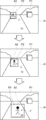
- the photographing device 10 is a portable photographing device, specifically, a digital camera having the appearance shown in FIGS. 1 and 2, and is used for photographing a still image and a moving image.
- a portable photographing device specifically, a digital camera having the appearance shown in FIGS. 1 and 2, and is used for photographing a still image and a moving image.
- the function of photographing a moving image in real time will be mainly described.
- the photographing device 10 is composed of a photographing device main body 12 and a housing 14.
- the photographing device main body 12 is a portion of the photographing device 10 excluding the housing 14.
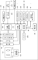
- the housing 14 has substantially the same structure as the housing of a general digital camera, and houses the photographing unit 20 and the processing unit 30 shown in FIG. 3 inside.
- the photographing unit 20 captures an image and has a lens unit 110, a lens driving unit 120, an aperture unit 130, a shutter 140, an image sensor 150, and an A / D (Analog / Digital) converter 160 as shown in FIG. ..
- the lens unit 110 includes a zoom lens 112 and a focus lens 114, and in the first embodiment, the zoom lens 112 is equipped with an anamorphic lens. Therefore, in the first embodiment, it is possible to shoot an image with a wide angle of view in the horizontal direction (for example, an angle of view with an aspect ratio of 2.35: 1).
- the lens is not limited to an anamorphic lens, and a wide-angle lens, an ultra-wide-angle lens, a 360-degree lens, or the like may be used.
- the lens unit 110 may be configured to be interchangeable with another lens unit.
- the photographing unit 20 may include a plurality of lens units 110 having different angles of view.
- the angle of view when the image sensor 150 captures an image is determined according to the specifications of the lens unit 110 and the image sensor 150, and the image captured at that angle of view is the "reference image" of the present invention. Equivalent to.
- the lens drive unit 120 includes a drive motor (not shown) and a drive mechanism (not shown), and moves the lens of the lens unit 110 along the optical axis.
- the aperture 130 adjusts the size of the opening according to the user's setting or automatically, and adjusts the amount of light passing through the opening.
- the shutter 140 blocks the transmitted light to the image sensor 150.
- the image sensor 150 is composed of, for example, a CCD (Charged Coupled Device) or a CMOS (Complementary Metal Oxide Semiconductor Image Sensor), and receives light from a subject via a lens unit 110 to form an image and obtains image data. Generate. Specifically, the image sensor 150 converts an optical signal received through a color filter into an electric signal by a light receiving element, amplifies the electric signal by an AGC (Auto Gain Controller), and analog image data from the amplified signal. To generate.
- CMOS Complementary Metal Oxide Semiconductor Image Sensor
- the A / D converter 160 converts the analog image data generated by the image sensor 150 into digital image data.
- This digital image data corresponds to the data of the frame image constituting the reference image which is a moving image.
- the number of pixel data (that is, the number of pixels) constituting the digital image data is not particularly limited, but in the first embodiment, the number of pixels is 10 million or more, and the lower limit of the number of pixels is preferably 60 million or more. It is good to be. Further, the preferable upper limit of the number of pixels in the first embodiment is 1 billion or less, more preferably 500 million or less. If the number of pixels exceeds the lower limit, the visibility of the extracted video extracted from the reference video (the extracted video will be described later) can be guaranteed. Further, if the number of pixels is less than the upper limit, the amount of pixel information of the reference image can be reduced, and the processing speed of the processing unit 30 is increased.
- the processing unit 30 executes various processes related to the photographing device 10, and in the first embodiment, the processing unit 30 includes a control processing unit 210 and a video processing unit 220 as shown in FIG.
- the processing unit 30 is composed of, for example, one or a plurality of processors, specifically, a CPU (Central Processing Unit) and a control program.
- processors are not limited to this, and the above processors are FPGA (Field Programmable Gate Array), DSP (Digital Signal Processor), ASIC (Application Specific Integrated Circuit), GPU (Graphics Processing Unit), MPU (Micro- It may be configured by a Processing Unit) or another IC (Integrated Circuit), or may be configured by combining these.
- SoC System on Chip :
- the functions of the entire system including the control processing unit 210 and the video processing unit 220 are configured by one IC (Integrated Circuit) chip. May be good.
- the hardware configuration of each processor described above may be realized by an electric circuit (Circuitry) in which circuit elements such as semiconductor elements are combined.
- the control processing unit 210 can control each part of the photographing device main body 12 according to the user's operation or automatically, for example, control the photographing unit 20 to cause the photographing unit 20 to take (acquire) a reference image. Further, the control processing unit 210 can control the video processing unit 220 so that the video (specifically, the extracted video described later) is recorded on the recording medium. Further, the control processing unit 210 focuses the lens unit 110 on the subject in the image based on the contrast of the entire image or a part of the image indicated by the digital image data generated by the photographing unit 20. The drive unit 120 can be controlled. Further, the control processing unit 210 controls the aperture unit 130 based on the brightness of all or a part of the image indicated by the digital image data generated by the photographing unit 20, and automatically adjusts the exposure amount at the time of photographing. be able to.
- the video processing unit 220 performs processing such as gamma correction, white balance correction, and scratch correction on the digital image data generated by the photographing unit 20, and further compresses the digital image data in a compression format conforming to a predetermined standard. Then, the image processing unit 220 acquires a reference image from the compressed digital image data sequentially generated during shooting, and executes various processes on the acquired reference image.
- the image processing unit 220 can set an extraction range smaller than the angle of view of the shooting unit 20 and extract the extracted image (so-called crop image) reflected in the extraction range from the reference image. (See, for example, FIGS. 6 and 8). Further, the video processing unit 220 can record (record) the extracted video on a recording medium under the control of the control processing unit 210. The extracted video will be described in detail in a later section.
- each processing of the control processing unit 210 and the video processing unit 220 will be described as processing by the processing unit 30 which is the processor of the present invention.
- the processing by the processing unit 30 will be described in detail in a later section.
- the housing 14 further houses a built-in memory 230 built in the photographing device main body 12, a memory card 240 that can be attached to and detached from the photographing device main body 12 via the card slot 260, and a buffer 250. ..
- the built-in memory 230 and the memory card 240 are recording media on which the above-mentioned extracted video is recorded, and are composed of a flash memory, a ferroelectric memory, or the like.
- the recording medium may be located in a place other than the photographing apparatus main body 12, and the processing unit 30 may record video on an external recording medium via wired or wireless communication.
- the buffer 250 functions as a work memory of the processing unit 30, and is composed of, for example, a DRAM (Dynamic Random Access Memory), a ferroelectric memory, or the like.
- a display 40 is attached to the back surface of the housing 14.
- the display 40 is composed of an LCD (Liquid Crystal Display) or an organic EL (Organic Electroluminescence) display, an LED (Light Emitting Diode) display, electronic paper, or the like.
- the above-mentioned extracted video is displayed on the display 40, and a setting screen for shooting conditions and the like, a screen for mode selection, and the like are also displayed as appropriate.
- the housing 14 is provided with an operation unit 50, and the user performs various operations related to shooting through the operation unit 50.
- the operation unit 50 includes, for example, a release button 310, a zoom lever 320, operation dials 330, 340, and a cross button 350 arranged on the outer surface of the housing 14.
- these devices transmit various control signals to the processing unit 30.
- a control signal for changing the zoom magnification is transmitted to the processing unit 30, and the processing unit 30 moves the zoom lens 112 according to the control signal. Controls and drives the lens driving unit 120.
- the display 40 is a touch panel display and is also used as the operation unit 50.
- a control signal corresponding to the touch position is transmitted to the processing unit 30.
- a mode selection screen (see FIG. 9), which will be described later, is displayed on the display 40, and when the user touches one of the plurality of mode selection buttons drawn on the screen, the selected mode is set.
- a control signal for setting is transmitted to the processing unit 30.
- the user can instruct the processing unit 30 to execute the zoom processing or the shutter processing (shooting processing) through the operation of touching a predetermined position on the screen of the display 40.
- the detector 60 is attached to the housing 14.
- the detector 60 detects the movement of the photographing device 10 including the housing 14, and more specifically, detects the horizontal movement of the housing 14.
- the horizontal movement of the housing 14 means that the photographing device 10 is centered on the vertical axis C so that the front direction of the photographing device 10 is changed so that the user can change the angle of view of the photographing. This is the movement of the housing 14 when the housing 14 is moved (strictly speaking, rotated).
- FIG. 4 is a view of the photographing device 10 as viewed from above.
- the detector 60 is composed of, for example, a gyro sensor attached to the housing 14, and has an angular velocity and a rotation amount (symbol ⁇ in FIG. 4) when the housing 14 moves in the horizontal direction.
- the movement of the housing 14 is detected based on the measurement result.
- the detector 60 is not limited to the gyro sensor, and may be composed of a motion sensor other than the gyro sensor, for example, an acceleration sensor or the like. Further, the movement of the housing 14 may be detected by using the image processing device as the detector 60 and analyzing the reference image to determine whether or not there is a change in the angle of view.
- the extracted image is an image set smaller than the angle of view, is extracted from the reference image, and is displayed on the display 40.
- the reference image is a high-quality image composed of 10 million or more (preferably 60 million or more) pixels
- the extracted image extracted from the reference image is also a sufficiently high-quality image.
- the outer edge of the extracted image has a rectangular shape, but the shape of the outer edge is not particularly limited, and is square, parallelogram, trapezoidal, rhombic, circular, or It may be an ellipse, a triangle, a polygon more than a pentagon, or an indefinite shape.
- the position, size, aspect ratio, etc. of the extraction range are initially set, and usually, a predetermined range within the angle of view is set as the extraction range.
- the position, size, aspect ratio, etc. of the extraction range may be set and changed on the user side. For example, a setting screen (not shown) is displayed on the display 40, and the user sets and changes through the setting screen. You may.
- the processing unit 30 moves the extraction range over time within the angle of view.
- moving with time means moving the extraction range relative to the angle of view so that the position of the extraction range gradually changes, and the movement is stopped (interrupted) in the middle. It may also include the case of doing.
- a subject reflected in the extraction range can be set as a tracking target, and as shown in FIG. 5, the subject can be tracked within the angle of view. That is, the function of the processing unit 30 can automatically move the extraction range so that the subject fits within the extraction range in conjunction with the movement of the subject within the angle of view.
- the size of the image of the subject changes as shown in FIG. That is, the ratio of the size of the subject image to the size of the extraction range (hereinafter, referred to as the subject image ratio) changes. Therefore, in the first embodiment, as shown in FIG. 5, the size of the extraction range is changed according to the movement of the subject in the depth direction, that is, the change in the subject image ratio. Specifically, the size of the extraction range is adjusted so that the subject image ratio is maintained substantially constant. This size adjustment corresponds to the electronic zoom process described later.
- the display 40 can always display the extracted image including the subject to be tracked as shown in FIG. Further, in the displayed extracted video, the size of the subject to be tracked is kept substantially constant. Further, the user does not have to move the photographing device 10 by himself / herself to track the subject to be tracked, and therefore there is no manual change of the angle of view, and the image is disturbed (image blur, etc.) that occurs when the angle of view is changed manually. Can also be avoided. Such an effect is particularly effective when the angle of view is relatively widened by using an anamorphic lens or the like.
- the extraction range is from one end to the other end in the horizontal direction of the angle of view. Automatically slides (panning).
- the display 40 can display an image in which the shooting angle as shown in FIG. 8 is continuously changed in the horizontal direction, that is, a panoramic moving image.
- the user does not have to move the shooting device 10 by himself / herself to change the shooting angle, and therefore there is no manual change of the angle of view, and the distortion of the image (image blur, etc.) that occurs when the angle of view is changed manually is avoided. You can also do it.
- Such an effect is particularly effective when the angle of view is relatively widened by using an anamorphic lens or the like.
- the moving speed of the extraction range may be set in advance, and may be changed to an arbitrary speed by the user performing, for example, a button operation while moving the extraction range. Further, the time from the start of movement of the extraction range to the end of the extraction range reaching the end of the angle of view, that is, the time required for movement may be obtained. In this case, the remaining movement time tr based on the difference between the obtained required time and the elapsed time from the start of movement may be displayed on the display 40 as shown in FIG.
- the automatic movement (panning) of the extraction range based on the function of the processing unit 30 and the movement operation (operation for changing the angle of view) of the photographing device 10 by the user may be performed at the same time.
- the extraction range movement modes are a first mode in which the extraction range is moved so as to track the subject to be tracked (hereinafter referred to as a tracking mode) and a second mode in which the extraction range is moved in a fixed direction. (Hereinafter referred to as panning mode) and.
- the user can select any one of the modes on the mode selection screen shown in FIG. 9, for example, and the processing unit 30 moves the extraction range within the angle of view according to the mode selected by the user.
- the movement mode of the extraction range may be specified based on the user's intention, specifically, the selection result on the mode selection screen shown in FIG.
- the photographing device 10 may analyze the reference image, automatically determine the presence or absence of the tracking target, and automatically specify the movement mode based on the determination result.
- the tracking mode is selected when the subject to be tracked exists, and the panning mode is selected when the subject to be tracked does not exist.
- the detector 60 may detect the moving speed (specifically, the angular velocity) and the like, and automatically specify the moving mode based on the detection result.
- the tracking mode is selected when the movement speed is random
- the panning mode is selected when the movement speed is constant.
- processing of the processing unit 30 is roughly classified into a processing executed by the control processing unit 210 and a processing executed by the video processing unit 220.
- Examples of the former processing include shooting processing, autofocus processing, optical zoom processing, optical image stabilization, and the like.
- Examples of the latter process include electronic zoom processing, electronic image stabilization processing, setting processing, extraction processing, determination processing, movement processing, recording processing, warning processing, and the like. The outline of each of the above processes will be described below.
- the shooting process is a process in which the processing unit 30 controls the shooting unit 20 to shoot an image at the angle of view of the photographing unit 20, that is, a reference image.
- the shooting process is automatically started, for example, when the shooting device 10 is activated.
- the autofocus process is a process in which the processing unit 30 controls the lens driving unit 120 so that the focus lens 114 of the lens unit 110 moves along the optical axis.
- the autofocus process is executed in a timely manner, for example, while the extraction range is moving. This makes it possible to focus on a subject within the moving extraction range.
- the optical zoom process is an example of the zoom process, and is a process of performing optical zoom on the image of the subject in the extracted image. Specifically, when the user operates the zoom lever 320 as the zoom operation unit, the optical zoom process is executed, and the processing unit 30 controls the lens drive unit 120 to move the zoom lens 112 along the optical axis. ..
- Another example of the zoom operation unit includes a rotating ring for zoom operation in the lens unit 110.
- the optical zoom process is used in combination with the electronic zoom process. For example, when the image quality of the extracted image deteriorates (coarse) due to frequent execution of the electronic zoom process during shooting, the optical zoom process is appropriately executed in order to improve the image quality.
- the optical image stabilization process is an example of the image stabilization process, and is a process for stabilizing the extracted image by suppressing the influence of vibration or the like applied to the photographing device 10 during photographing.
- the processing unit 30 controls the lens driving unit 120 to move the lens unit 110 to shift the optical axis.
- the optical image stabilization is realized by a known technique, and for example, the optical image stabilization technique described in Japanese Patent No. 5521518 can be used.
- the electronic zoom process is an example of the zoom process, and is a process of performing an electronic zoom (digital zoom) on the image of the subject in the extracted image.
- the processing unit 30 changes the size of the extraction range within the angle of view (in other words, the number of pixels of the extracted video).
- the electronic zoom process is executed in a timely manner, for example, while the extraction range is moving. For example, when the subject within the extraction range moves in the depth direction of the photographing device 10 and the size of the image of the subject to be tracked changes, the electronic zoom process is executed in order to adjust the subject image ratio described above. ..
- the size of the extraction range is changed according to the distance between the photographing device 10 and the subject in the extracted image.
- the distance between the photographing device 10 and the subject in the extracted image can be measured by using a distance measuring technique mounted on a general digital camera.
- a distance measurement method using a phase difference method using retardation pixels a method of measuring the distance to a subject based on the flight time of light by a TOF (Time of Flight) method, and the like can be used.
- the size (display size) of the subject to be tracked can be kept constant by analyzing the extracted video while the extraction range is moving.
- the electronic image stabilization process is an example of the image stabilization process, and is a process in which the processing unit 30 shifts the position of the extraction range in order to suppress the influence of vibration or the like applied to the photographing device 10 during photographing and stabilize the extracted image.
- the electronic image stabilization is realized by a known technique, for example, the technique of electronic image stabilization (EIS) described in Japanese Patent No. 5521518 or International Publication No. 2016/181717.
- EIS electronic image stabilization
- the immediately preceding frame image among the frame images constituting the reference image is stored in the buffer 250 during shooting.
- the processing unit 30 compares the frame image with the immediately preceding frame image stored in the buffer 250 to obtain the amount of deviation of the image within the extraction range. Then, when the obtained deviation amount exceeds the threshold value, the electronic image stabilization process is executed.
- the setting process is a process in which the processing unit 30 sets the extraction range within the angle of view in the reference image. Normally, the setting process is executed when the photographing device 10 is activated, and in the setting process at this time, the position, size, aspect ratio, and the like of the extraction range are set as initial values. However, the present invention is not limited to this, and the user may set the position, size, aspect ratio, etc. of the extraction range through the operation unit 50, and may change the extraction range as appropriate after the setting.
- the extraction range is set based on the subject to be tracked.
- the user moves the photographing device 10 so that one subject existing within the angle of view is displayed on the display 40 for a certain period of time or longer, and specifically, the angle of view is changed or zoomed.
- the processing unit 30 recognizes the subject as a subject to be tracked and sets the extraction range so that the subject fits.
- the procedure for setting the extraction range based on the subject may be a procedure other than the procedure described above. For example, the entire screen of the reference image may be displayed on the display 40, and the user may touch a subject reflected in the reference image to set the extraction range so that the subject fits.
- the extraction process is a process in which the processing unit 30 extracts (that is, cuts out) the extracted video that appears within the extraction range from the reference video. For example, when the tracking mode is selected, a certain range of images including the image of the subject to be tracked is extracted as the extracted image. When the panning mode is selected, the extracted video is extracted so that the subject changes (slides) sequentially. The extracted video is displayed on the display 40 as shown in FIGS. 6 and 8, and the user can check the extracted video through the display 40.
- the determination process is a process in which, when the detector 60 detects the movement of the housing 14, the processing unit 30 determines whether or not the end of the extraction range reaches the end of the angle of view due to the movement.
- the determination process is executed.
- the determination process will be specifically described with reference to FIG.
- the detector 60 detects the movement of the housing 14 at that time.
- the side facing the photographing device 10 when moving in the horizontal direction is the first side, and the opposite side is the second side.
- the left side corresponds to the first side
- the right side corresponds to the second side.
- the processing unit 30 extracts the amount corresponding to the movement amount of the housing 14 by the electronic image stabilization process (EIS) described above. Shift the range to the second side in the horizontal direction.
- EIS electronic image stabilization process
- the extraction range moves to the second side relative to the angle of view.
- the processing unit 30 executes the determination process and determines whether or not the end of the extraction range located on the second side has reached the end of the angle of view located on the second side by the above relative movement. The judgment result in the judgment result is reflected in whether or not the movement process is executed.
- the movement process is a process that is executed during shooting and the processing unit 30 moves the extraction range at the angle of view over time.
- the movement process is executed according to the detected movement. The relationship between the movement of the housing 14 detected by the detector 60 and the execution of the movement process will be described in detail in a later section.
- the processing unit 30 causes the display 40 to display the extracted image while the extraction range is moving.
- the housing 14 moves (vibrates) due to vibration from the user or the ground being transmitted to the photographing device 10 during the execution of the movement process
- the extracted image while the extraction range is moving is referred to.
- the electronic image stabilization process or the optical image stabilization process described above is executed. As a result, the blurring of the extracted image displayed on the display 40 is reduced, and the displayed image becomes stable.
- the method of moving the extraction range in the movement process differs depending on the selected mode of the tracking mode and the panning mode.
- the processing unit 30 sets the subject reflected in the extraction range as the tracking target. Then, in the movement process, the processing unit 30 moves the extraction range so that the subject to be tracked falls within the extraction range (strictly speaking, it falls within the extraction range).
- the subject to be tracked is searched within the angle of view, and the extraction range is moved in conjunction with the movement of the subject to be tracked.
- the algorithm for searching the subject to be tracked within the angle of view is not particularly limited.
- the image of the subject set as the tracking target is stored in the buffer 250 as a template image, and a known template matching technique is applied to compare the above template image with the reference image.
- the image of the part that matches the template image may be specified.
- the moving speed of the extraction range is set to a speed corresponding to the moving speed of the subject so that the subject to be tracked can be tracked.
- the moving speed of the extraction range is the number of pixels that the moving extraction range passes through in a unit time when the angle of view is divided in pixel units.
- the extraction range is moved from one end in the horizontal direction of the angle of view to the other end.
- the moving speed of the extraction range at this time may be a constant speed, for example, depending on the moving speed (specifically, the angular velocity) in the horizontal movement of the housing 14 detected by the detector 60. It may be speed.
- the movement speed of the extraction range can be changed by the user operating the operation unit 50 or the like while the movement process is being executed (that is, while the extraction range is being moved). You may.
- the processing unit 30 zooms the moving speed of the extraction range in the move process (specifically, after the change). Adjust according to the zoom magnification of. Specifically, the processing unit 30 reduces the moving speed in the case of zooming up and increases the moving speed in the case of zooming out. This makes it possible to eliminate the abnormal appearance of the extracted video described above.
- the processing unit 30 ends the move process when any of the following end conditions (J1) to (J5) is satisfied.
- (J1) When the user instructs the end of the move process through the operation unit 50 during the execution of the move process.
- J2 When the user moves the housing 14 in the direction opposite to the moving direction of the extraction range during the execution of the moving process, and the detector 60 detects the movement.
- J3 When the tracking mode is selected and the subject to be tracked deviates from the angle of view during the execution of the movement process.
- J4 When the tracking mode is selected and the subject to be tracked is stopped (still) for a certain period of time or longer during the execution of the movement process.
- the end condition of the movement process is not limited to the above five conditions, and conditions other than the above five conditions may be further included, and one to four of the above five conditions are not included. May be good.
- the recording process is a process in which the processing unit 30 records the extracted video on a recording medium including a built-in memory 230, a memory card 240, and the like.
- the recording process starts when, for example, the release button 310 is pressed once, and ends when the release button 310 is pressed again.
- the processing unit 30 records the extracted video on the recording medium while the extraction range is moving due to the moving process in the recording process. If at least one of optical zoom processing, electronic zoom processing, optical image stabilization processing, and electronic camera shake processing is executed during execution of the movement processing, the recording processing records the extracted video after the processing. ..
- the recording process is completed in conjunction with the movement process.
- the present invention is not limited to this, and both the extracted video and the reference video may be recorded on the recording medium.
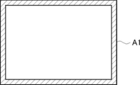
- the warning process is a process in which the processing unit 30 issues a warning to the user when a predetermined situation is reached during the execution of the move process. For example, when the movement process is being executed in the tracking mode, when the moving extraction range approaches the area near the edge of the angle of view within the angle of view, a warning process is performed to notify the user to that effect. As shown in FIG. 11, the area near the angle of view edge corresponds to the range from the position to the end of the angle of view, which is separated by a predetermined distance from the edge of the angle of view, and is the hatched range in FIG. Is.
- the warning method in the warning process is not particularly limited, and examples thereof include displaying a warning message or changing the outer frame of the extracted video to a predetermined color (specifically, red or the like). ..
- the image is photographed using the photographing method of the present invention. Then, when the detector 60 detects the movement of the housing 14 during shooting, the processing unit 30 executes the movement processing according to the detected movement of the housing 14. More specifically, in the first embodiment, when the user moves the photographing device 10 for the purpose of changing the angle of view or the like, the detector 60 detects the movement of the housing 14 at that time, and the processing unit 30 moves with that as an opportunity. Execute the process.
- the extraction range automatically moves so as to track the subject or toward the edge of the angle of view.
- the detector 60 detects the movement of the housing 14
- the user does not need to move the photographing device 10 again to change the angle of view, and as a result, the user can concentrate on photographing. That is, it becomes easier for the user to record the extracted video while moving the extraction range.
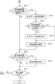
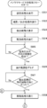
- the processing unit 30 executes the setting process (S001), and sets the extraction range within the angle of view according to the initial value, the input value of the user, or the like.
- This step S001 corresponds to the setting process.
- shooting of the reference image is started at the angle of view of the photographing device 10, and the processing unit 30 executes the extraction process to extract the extracted image from the reference image (S002).
- This step S002 corresponds to the extraction step. Further, by executing the extraction step, the extracted image is displayed on the display 40 (S003).
- the processing unit 30 executes the recording process and starts recording the extracted video (S004).
- the recording process is started by pressing the release button 310.
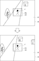
- the user moves (moves) the photographing device 10 in order to track a certain subject.
- the subject J shown in FIG. 14 moves, the user moves the photographing device 10 so that the subject J continues to be within the extraction range as shown in the figure.
- the detector 60 detects the movement of the housing 14 at this time (S005).
- the upper figure in FIG. 14 shows the angle of view immediately before moving the photographing device 10, and the lower figure in FIG. 14 shows the angle of view immediately after moving the photographing device 10.
- the processing unit 30 compares the extracted images before and after the motion is detected by the detector 60, and selects the subject J that is commonly reflected in both extracted images as the tracking target. (S006). At this time, the processing unit 30 can recognize the subject J reflected in the extracted image before and after the motion is detected by the detector 60 by using the template matching technique or the like described above.
- the method for selecting the tracking target is not limited to the above method, and the user may specify the subject by touching the image of the subject on the display 40, and the tracking target may be selected based on the designation operation.
- the extracted images before and after the motion is detected by the detector 60 may be compared, and the subject with the smallest amount of movement may be selected as the tracking target among the subjects displayed in each extracted image.
- the processing unit 30 executes the movement process and moves the extraction range within the angle of view so that the subject J is within the extraction range as shown in FIG. 5 (S007).
- This step S007 corresponds to the moving step.
- the processing unit 30 may move the extraction range at a preset moving speed, or the moving speed according to the speed of the subject J calculated by analyzing the extracted video (for example, the subject J).
- the extraction range may be moved at the same speed as).
- the processing unit 30 moves the extraction range in the movement process, and displays the extracted image on the display 40 while the extraction range is moving (see FIG. 6). Further, in the recording process executed at the same time as the move process, the processing unit 30 records the extracted video on the recording medium while the extraction range is moving due to the move process. That is, the recording step of recording the extracted video while the extraction range is moving by the moving step is executed.
- the processing unit 30 (S008), the electronic image stabilization process or the optical image stabilization described above
- the correction process is executed (S009).
- camera shake correction is performed on the extracted video while the extraction range is moving.
- the processing unit 30 executes the electronic zoom process and changes the size of the extraction range according to the distance between the photographing device 10 and the subject J (S011). In this way, the processing unit 30 moves the extraction range while changing the size of the extraction range based on the change in the subject image ratio in the movement process. Thereby, for example, the extraction range can be moved while maintaining the subject image ratio. As a result, while tracking the subject J, the image of the subject J can be displayed on the display 40 in a substantially constant size as shown in FIG.
- the processing unit 30 executes the above-mentioned optical zoom process to perform optical zoom on the image of the subject in the extracted image (S013). As a result, it is possible to recover the image quality of the extracted video that has deteriorated due to the execution of the electronic zoom processing.
- a notification urging the user to perform optical zoom processing may be displayed on the display 40.
- the processing unit 30 adjusts the moving speed of the extraction range according to the electronic zoom or the optical zoom (S014).
- the processing unit 30 moves the extraction range at the adjusted movement speed, that is, the movement speed according to the electronic zoom or the optical zoom.
- the processing unit 30 determines whether or not the extraction range during movement is approaching the above-mentioned area near the end of the angle of view in terms of angle of view (S015). Then, when the extraction range is approaching the area near the end of the angle of view, the processing unit 30 executes warning processing (S016). As a result, it is possible to notify the user that the extraction range is approaching the vicinity of the edge of the angle of view, and prompt the user to perform an operation for changing the angle of view, an operation for instructing the end of shooting, and the like.
- steps S007 to S016 are repeatedly executed during the move process. Then, during the execution of the move process, the processing unit 30 ends the move process when any of the above-mentioned end conditions (J1) to (J4) is satisfied (S017). At this time, the recording process may be terminated at the end of the move process, or the recording process may be continued after the end of the move process.
- the user moves the photographing device 10 so as to follow the subject J again, and when the detector 60 detects the movement of the housing 14 at that time, the movement process is executed again, and the above-mentioned series of processes ( S006 to S017) are repeated.
- the procedure (S021 to S024) from when the user activates the photographing device 10 to when the release button 310 is pressed to execute the recording process is the same as when the tracking mode is selected. .. That is, even when the panning mode is selected, the setting step and the extraction step are executed, and the recording step is started by pressing the release button 310.
- the user moves the photographing device 10 to the first side in the horizontal direction.
- the detector 60 detects the movement of the housing 14 at that time, that is, the movement to the first side in the horizontal direction (S025).
- the processing unit 30 uses the above-mentioned EIS to shift the extraction range to the second side in the horizontal direction by the amount corresponding to the movement amount of the housing 14 (S026). ).
- the processing unit 30 executes a determination process and determines whether or not the second end of the extraction range has reached the second end of the angle of view (S027).
- the processing unit 30 executes a movement process and sets the extraction range horizontally as shown in FIG. It is moved toward the first side in the direction (S028). This step S028 corresponds to the moving step.
- the processing unit 30 sets the moving speed of the extraction range when executing the moving process, and in the moving process, moves the extraction range at the set moving speed.
- the moving speed of the extraction range is set according to the horizontal moving time tx.
- the horizontal movement time tx is the time from the start of the horizontal movement of the housing 14 detected by the detector 60 to the end of the second side of the extraction range reaching the second end of the angle of view.
- the horizontal movement time tx is, for example, the angular velocity in the horizontal movement of the housing 14 detected by the detector 60, or the second end of the extraction range is moving toward the second end of the angle of view. It can be calculated from the moving speed.
- the speed of the extraction range during execution of the movement process may be constant or may be changed, and may be changed to an arbitrary speed by, for example, the user operating the operation unit 50.
- the processing unit 30 moves the extraction range in the movement process, and displays the extracted image on the display 40 while the extraction range is moving (see FIG. 8). At this time, the processing unit 30 may obtain the time from the start of movement until the end of the extraction range reaches the end of the angle of view (that is, the time required for movement) from the movement speed of the extraction range. Further, the processing unit 30 may display the remaining movement time tr based on the difference between the obtained required time and the elapsed time from the start of movement on the display 40. Further, in the recording process executed at the same time as the move process, the processing unit 30 records the extracted video on the recording medium while the extraction range is moving due to the move process. That is, the recording step of recording the extracted video while the extraction range is moving by the moving step is executed.
- the processing unit 30 performs the electronic image stabilization process or the optical image stabilization process. Execute (S030). In this step S030, camera shake correction is performed on the extracted video while the extraction range is moving. As a result, the extracted image that changes with the movement of the extraction range can be stabilized, and the extracted image can be smoothly changed even when camera shake or the like occurs.
- the processing unit 30 determines whether or not the extraction range during movement is approaching the area near the end of the angle of view within the angle of view (S031). Then, when the extraction range is approaching the area near the end of the angle of view, the processing unit 30 executes warning processing (S032). As a result, it is possible to notify the user that the extraction range is approaching the vicinity of the edge of the angle of view.
- the processing unit 30 ends the movement process.
- the recording process may be terminated at the end of the move process, or the recording process may be continued after the end of the move process.
- step S027 is executed again. Then, when it is determined by the determination process that the end on the second side of the extraction range has reached the end on the second side of the angle of view, the movement process is executed again, and the series of processes (S028 to S034) described above are repeated. Is done.
- the image of the subject in the extracted image is zoomed (specifically, electronic) during the execution of the movement process. Zoom and optical zoom) may be performed. In that case, it is preferable to adjust the moving speed of the extraction range according to the zoom, and then move the extraction range at the moving speed adjusted according to the subsequent movement processing and zoom.
- the photographing apparatus of the present invention has been described above with specific embodiments, the above-described first embodiment is merely an example, and other embodiments are also conceivable.
- the image pickup apparatus main body 12X of the photographing apparatus and the external monitor 70 may be connected by a wired system or a wireless system.
- the external monitor 70 is composed of a display device such as a liquid crystal monitor, a recorder with a monitor, or an information processing terminal with a monitor such as a personal computer, a smartphone, and a tablet terminal.
- the processing unit 30 transmits the video signal of the extracted video to the external monitor 70, and the extracted video is displayed on the external monitor 70 side.
- the extracted image may be displayed on the external monitor 70.
- the extracted image may be displayed on both the display 40 of the photographing device and the external monitor 70.
- the processing unit 30 may move the extraction range according to the movement of the housing 14 in the vertical direction detected by the detector 60 in the movement processing.
- the extraction range is slid and moved in the horizontal direction in the movement process when the panning mode is selected, but the present invention is not limited to this.
- the extraction range may be slid up and down in the movement process.
- the processing unit 30 automatically executes the movement process in conjunction with the detection of the movement of the photographing device 10, and moves the extraction range so as to track the subject.
- the present invention is not limited to this, and the subject in the extracted image is set as the tracking target by the user operating the touch panel or the like, and the movement process is executed based on the operation of the process start instruction by the user. May be good. Such a case will be described in detail below as a second embodiment of the present invention.
- the basic configuration of the photographing apparatus according to the second embodiment is substantially the same as that of the photographing apparatus 10 described above, and is as shown in FIG. That is, the photographing apparatus according to the second embodiment includes a photographing unit 20 and a processing unit 30 (processor).
- the processing unit 30 executes setting processing, extraction processing, movement processing, zoom processing, and recording processing.
- the extraction range is set within the angle of view based on the contents of the initial setting or the operation instructed by the user.
- the extraction process is the same process as the above-mentioned extraction process, and in this process, the extracted video reflected in the extraction range is extracted.
- the user specifies, for example, by moving the photographing device to change the angle of view, tracking the subject in the extracted image, and touching the subject on the touch panel. As a result, the designated subject is set as the tracking target.
- the extraction range is moved over time so that the subject to be tracked is within the extraction range.
- the image of the subject is always included in the extracted image while the extraction range is moving.
- the extraction range is moved, and the extraction image while the extraction range is moving is displayed on the display 40.
- the processing unit 30 executes the movement process with this as an opportunity.
- the zoom processing is an electronic zoom processing and an optical zoom processing, and in either of the zoom processings, the image of the subject in the extracted image is zoomed.
- the processing unit 30 executes electronic zoom processing in order to change the size of the extraction range according to the distance between the subject and the photographing device.
- the processing unit 30 executes the optical zoom processing in order to improve the deteriorated image quality, or notifies the user to perform the optical zoom processing. Is displayed on the display 40. In the recording process, the extracted video is recorded on the recording medium while the extraction range is moving due to the moving process.
- the size of the extraction range that is, the number of pixels of the extracted video changes before and after the zoom.
- the moving speed of the extraction range that is, the number of pixels that the extraction range passes through per unit time is the same before and after zooming. In that case, to the user who confirms the extracted image through the display 40, the moving speed of the extraction range seems to have changed suddenly.
- the processing unit 30 when the zoom process is executed during the move process, in the move process after the zoom process, the processing unit 30 responds to the zoom (specifically, electronic zoom or optical zoom) performed in the zoom process. Move the extraction range at the same moving speed. This makes it possible to avoid a situation in which the moving speed of the extraction range seems to change suddenly due to the zoom described above.
- the movement process of the second embodiment is not limited to the case where the extraction range is moved in order to track the subject described above.
- it may be a case where the extraction range is slid from one end to the other end of the angle of view, that is, a movement process when the panning mode is selected.
- the zoom process can be executed even during the execution of such a move process, and in the move process after the zoom process, it is preferable that the processing unit 30 moves the extraction range at a move speed corresponding to the zoom.
- a setting step an extraction range smaller than the angle of view is set within the angle of view when the reference image is captured by the image sensor 150.
- the extraction step the extracted video of the extraction range is extracted from the reference video.
- zoom step zooming (optical zoom or electronic zoom) is performed on the image of the subject in the extracted image.
- moving step the extraction range at the angle of view is moved over time at a moving speed corresponding to the zoom performed in the zoom step.
- the recording step the extracted video is recorded on the recording medium while the extraction range is moving due to the moving step.
- Imaging device 10 Imaging device 12, 12X Imaging device body 14 Housing 20 Imaging unit 30 Processing unit 40 Display 50 Operation unit 60 Detector 70 External monitor 110 Lens unit 112 Zoom lens 114 Focus lens 120 Lens drive unit 130 Aperture unit 140 Shutter 150 Image Sensor 160 A / D converter 210 Control processing unit 220 Video processing unit 230 Built-in memory 240 Memory card 250 Buffer 260 Card slot 310 Release button 320 Zoom lever 330, 340 Operation dial 350 Cross button C Vertical axis
Landscapes
- Engineering & Computer Science (AREA)
- Multimedia (AREA)
- Signal Processing (AREA)
- Physics & Mathematics (AREA)
- General Physics & Mathematics (AREA)
- Theoretical Computer Science (AREA)
- Human Computer Interaction (AREA)
- Computer Vision & Pattern Recognition (AREA)
- Studio Devices (AREA)
- Indication In Cameras, And Counting Of Exposures (AREA)
- Adjustment Of Camera Lenses (AREA)
Priority Applications (3)
| Application Number | Priority Date | Filing Date | Title |
|---|---|---|---|
| JP2021546533A JP7385667B2 (ja) | 2019-09-20 | 2020-07-21 | 撮影装置、及び撮影方法 |
| US17/689,718 US11696033B2 (en) | 2019-09-20 | 2022-03-08 | Imaging apparatus and imaging method |
| US18/317,373 US12058444B2 (en) | 2019-09-20 | 2023-05-15 | Imaging apparatus and imaging method |
Applications Claiming Priority (2)
| Application Number | Priority Date | Filing Date | Title |
|---|---|---|---|
| JP2019-171661 | 2019-09-20 | ||
| JP2019171661 | 2019-09-20 |
Related Child Applications (1)
| Application Number | Title | Priority Date | Filing Date |
|---|---|---|---|
| US17/689,718 Continuation US11696033B2 (en) | 2019-09-20 | 2022-03-08 | Imaging apparatus and imaging method |
Publications (1)
| Publication Number | Publication Date |
|---|---|
| WO2021053967A1 true WO2021053967A1 (ja) | 2021-03-25 |
Family
ID=74884193
Family Applications (1)
| Application Number | Title | Priority Date | Filing Date |
|---|---|---|---|
| PCT/JP2020/028240 Ceased WO2021053967A1 (ja) | 2019-09-20 | 2020-07-21 | 撮影装置、及び撮影方法 |
Country Status (3)
| Country | Link |
|---|---|
| US (2) | US11696033B2 (https=) |
| JP (1) | JP7385667B2 (https=) |
| WO (1) | WO2021053967A1 (https=) |
Families Citing this family (3)
| Publication number | Priority date | Publication date | Assignee | Title |
|---|---|---|---|---|
| CN118985134A (zh) * | 2022-03-31 | 2024-11-19 | 索尼集团公司 | 图像处理装置、图像处理方法和程序 |
| US12177563B2 (en) * | 2022-12-30 | 2024-12-24 | Akap Innovation, Llc | Image capture device having an event mode and method thereof |
| US12451103B2 (en) * | 2023-10-20 | 2025-10-21 | LiveWired, LLC | Automatic adjustment of operating characteristics of mobile electronic devices |
Citations (2)
| Publication number | Priority date | Publication date | Assignee | Title |
|---|---|---|---|---|
| JP2015179988A (ja) * | 2014-03-19 | 2015-10-08 | 日本テレビ放送網株式会社 | 画像処理システム、画像処理装置、画像処理方法及びプログラム |
| JP2020122883A (ja) * | 2019-01-31 | 2020-08-13 | キヤノン株式会社 | カメラ雲台装置 |
Family Cites Families (12)
| Publication number | Priority date | Publication date | Assignee | Title |
|---|---|---|---|---|
| JP4389749B2 (ja) | 2004-10-15 | 2009-12-24 | 株式会社ニコン | パンニング撮影可能なカメラおよび動画像編集用プログラム |
| JP2008011497A (ja) * | 2006-06-01 | 2008-01-17 | Canon Inc | カメラ装置 |
| JP4201809B2 (ja) * | 2006-11-13 | 2008-12-24 | 三洋電機株式会社 | 手ぶれ補正装置及び方法並びに撮像装置 |
| JP2009077363A (ja) * | 2007-08-24 | 2009-04-09 | Sony Corp | 画像処理装置、動画再生装置、これらにおける処理方法およびプログラム |
| US8149285B2 (en) * | 2007-09-12 | 2012-04-03 | Sanyo Electric Co., Ltd. | Video camera which executes a first process and a second process on image data |
| US8253812B2 (en) * | 2008-02-23 | 2012-08-28 | Sanyo Electric Co., Ltd. | Video camera which adopts a focal-plane electronic shutter system |
| JP2011066877A (ja) * | 2009-08-21 | 2011-03-31 | Sanyo Electric Co Ltd | 画像処理装置 |
| JP2011188225A (ja) * | 2010-03-09 | 2011-09-22 | Sanyo Electric Co Ltd | 電子カメラ |
| JP6557451B2 (ja) * | 2014-05-07 | 2019-08-07 | キヤノン株式会社 | 撮像装置およびその制御方法ならびにプログラム |
| JP2016027704A (ja) | 2014-07-04 | 2016-02-18 | パナソニックIpマネジメント株式会社 | 撮像装置 |
| JP6657684B2 (ja) | 2015-09-04 | 2020-03-04 | Jsr株式会社 | 硬化膜形成用組成物、硬化膜、発光表示素子及び硬化膜の形成方法 |
| JP2019022026A (ja) | 2017-07-14 | 2019-02-07 | キヤノン株式会社 | 撮像装置 |
-
2020
- 2020-07-21 JP JP2021546533A patent/JP7385667B2/ja active Active
- 2020-07-21 WO PCT/JP2020/028240 patent/WO2021053967A1/ja not_active Ceased
-
2022
- 2022-03-08 US US17/689,718 patent/US11696033B2/en active Active
-
2023
- 2023-05-15 US US18/317,373 patent/US12058444B2/en active Active
Patent Citations (2)
| Publication number | Priority date | Publication date | Assignee | Title |
|---|---|---|---|---|
| JP2015179988A (ja) * | 2014-03-19 | 2015-10-08 | 日本テレビ放送網株式会社 | 画像処理システム、画像処理装置、画像処理方法及びプログラム |
| JP2020122883A (ja) * | 2019-01-31 | 2020-08-13 | キヤノン株式会社 | カメラ雲台装置 |
Also Published As
| Publication number | Publication date |
|---|---|
| JP7385667B2 (ja) | 2023-11-22 |
| US20230283904A1 (en) | 2023-09-07 |
| US20220191400A1 (en) | 2022-06-16 |
| JPWO2021053967A1 (https=) | 2021-03-25 |
| US12058444B2 (en) | 2024-08-06 |
| US11696033B2 (en) | 2023-07-04 |
Similar Documents
| Publication | Publication Date | Title |
|---|---|---|
| US8284257B2 (en) | Image pick-up apparatus and tracking method therefor | |
| US12058444B2 (en) | Imaging apparatus and imaging method | |
| US20130258122A1 (en) | Method and device for motion enhanced image capture | |
| WO2016119301A1 (zh) | 一种终端、图像拍摄方法及装置 | |
| WO2006038577A1 (ja) | プロジェクタ装置を有する電子機器 | |
| WO2017037978A1 (ja) | 検出装置、検出方法、検出プログラムおよび撮像装置 | |
| CN109714533B (zh) | 电子设备 | |
| EP2645700A1 (en) | Method and device for motion enhanced image capture | |
| JP2012065173A5 (ja) | 撮影機器、画像表示方法及びプログラム | |
| JP7690628B2 (ja) | 表示方法、及び、映像処理方法 | |
| KR101589498B1 (ko) | 디지털 카메라 및 그 제어방법 | |
| JP2014107750A (ja) | 撮影機器 | |
| WO2011052120A1 (ja) | 撮影制御装置および撮影制御方法 | |
| JP6516426B2 (ja) | 撮像装置、画像処理方法及びプログラム | |
| JP7796262B2 (ja) | 映像作成方法 | |
| JP2009033237A (ja) | 電子カメラ | |
| US20210266450A1 (en) | Image capture apparatus and control method for same, and storage medium | |
| JP2006246354A (ja) | 撮影装置及び撮影プログラム | |
| KR20110090093A (ko) | 디지털 영상 처리 장치 및 그 제어 방법 | |
| JP2016032193A (ja) | 撮像装置 | |
| JP5504741B2 (ja) | 撮像装置 | |
| JP2011259341A (ja) | 撮像装置 | |
| JP2006229697A (ja) | 撮像装置 | |
| KR101336233B1 (ko) | 특정 부분 검출 및 알람 기능 화상 장치 및 그 방법 | |
| JP2013070298A (ja) | 撮像装置 |
Legal Events
| Date | Code | Title | Description |
|---|---|---|---|
| 121 | Ep: the epo has been informed by wipo that ep was designated in this application |
Ref document number: 20866856 Country of ref document: EP Kind code of ref document: A1 |
|
| ENP | Entry into the national phase |
Ref document number: 2021546533 Country of ref document: JP Kind code of ref document: A |
|
| NENP | Non-entry into the national phase |
Ref country code: DE |
|
| 122 | Ep: pct application non-entry in european phase |
Ref document number: 20866856 Country of ref document: EP Kind code of ref document: A1 |