WO2021049429A1 - 切削構造体、データ収集システム及び切削工具 - Google Patents
切削構造体、データ収集システム及び切削工具 Download PDFInfo
- Publication number
- WO2021049429A1 WO2021049429A1 PCT/JP2020/033565 JP2020033565W WO2021049429A1 WO 2021049429 A1 WO2021049429 A1 WO 2021049429A1 JP 2020033565 W JP2020033565 W JP 2020033565W WO 2021049429 A1 WO2021049429 A1 WO 2021049429A1
- Authority
- WO
- WIPO (PCT)
- Prior art keywords
- recess
- reference plane
- shank portion
- cutting
- cutting tool
- Prior art date
- Legal status (The legal status is an assumption and is not a legal conclusion. Google has not performed a legal analysis and makes no representation as to the accuracy of the status listed.)
- Ceased
Links
Images




Classifications
-
- B—PERFORMING OPERATIONS; TRANSPORTING
- B23—MACHINE TOOLS; METAL-WORKING NOT OTHERWISE PROVIDED FOR
- B23B—TURNING; BORING
- B23B27/00—Tools for turning or boring machines; Tools of a similar kind in general; Accessories therefor
-
- B—PERFORMING OPERATIONS; TRANSPORTING
- B23—MACHINE TOOLS; METAL-WORKING NOT OTHERWISE PROVIDED FOR
- B23Q—DETAILS, COMPONENTS, OR ACCESSORIES FOR MACHINE TOOLS, e.g. ARRANGEMENTS FOR COPYING OR CONTROLLING; MACHINE TOOLS IN GENERAL CHARACTERISED BY THE CONSTRUCTION OF PARTICULAR DETAILS OR COMPONENTS; COMBINATIONS OR ASSOCIATIONS OF METAL-WORKING MACHINES, NOT DIRECTED TO A PARTICULAR RESULT
- B23Q17/00—Arrangements for observing, indicating or measuring on machine tools
- B23Q17/09—Arrangements for observing, indicating or measuring on machine tools for indicating or measuring cutting pressure or for determining cutting-tool condition, e.g. cutting ability, load on tool
Definitions
- This disclosure relates to cutting structures, data collection systems and cutting tools.
- the cutting structure includes, for example, a cutting tool having a cutting edge and a tool post for holding the cutting tool.
- a cutting tool the cutting tool described in Patent Document 1 below is known.
- the cutting structure includes a cutting tool having a cutting edge and a tool post holding the cutting tool.
- the cutting tool has a substrate, a chip, and a sensor.
- the substrate is held by the tool post, and has a shank portion extending from the first end to the second end, a fixing portion located on the side of the first end of the shank portion, and a recess opened on the outer surface of the shank portion. And have.
- the insert is fixed to the fixed portion and has a cutting edge.
- the sensor is located in the recess.
- the tool post has a mounting surface and one or more urging portions. A substrate is placed on the mounting surface.
- the one or more urging portions have an abutting surface that abuts on the shank portion, and urges the shank portion from the abutting surface toward the mounting surface. When viewed in a plane in the urging direction of the urging portion, at least a part of the contact surface is separated from the recess.
- FIG. 2A is a diagram showing a state before the cutting tool is fixed to the tool post shown in FIG. 1
- FIG. 2B is a diagram showing a state before the cutting tool is fixed to the tool post shown in FIG. It is a figure which shows the state which the tool is fixed.
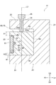
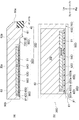
- It is a perspective view of the cutting tool shown in FIG. It is sectional drawing in the IV-IV line shown in FIG. It is an enlarged view of the region V shown in FIG. It is sectional drawing in the VI-VI line shown in FIG. It is a block diagram which shows the structure of a data collection system.
- FIG. 8A is a diagram showing a cutting tool according to the second embodiment, and FIG.
- FIG. 8B is an enlarged view of region VIIIb in FIG. 8A.
- 9 (a) is a diagram showing a cutting tool according to a third embodiment
- FIG. 9 (b) is an enlarged view of region IXb in FIG. 9 (a).
- 10 (a) is a view showing a cutting tool according to a fourth embodiment
- FIG. 10 (b) is an enlarged view of a region Xb in FIG. 10 (a).
- 11 (a) is a diagram showing a cutting tool according to a fifth embodiment
- FIG. 11 (b) is an enlarged view of region XIb in FIG. 11 (a).
- front and back is a term for specifying the positional relationship of the cutting tool along the longitudinal direction, and the side where the tip is located in the longitudinal direction is conveniently determined as the front, and the term "front” in the longitudinal direction is used. The other side is conveniently determined to be the rear.
- Left and right is a term for specifying the positional relationship when the end of the cutting tool is viewed from the rear.
- Up and down is a term for specifying the positional relationship when the end of the cutting tool is viewed from the rear as in the case of left and right, and is a term for specifying the positional relationship in the direction orthogonal to the left and right. ..
- Fr is front
- Rr is rear
- Le is left
- Ri right
- Up is up
- Dn is down.
- each of the drawings to be referred to is schematically shown, and details may be omitted.
- the tip is not limited to the front end (front end) and the rear end is not limited to the rear end. That is, the tip can be read as one end (one end), and the rear end can be read as the other end (the other end).
- the data collection system 10 may include a tool post 20, a cutting tool 30 (for example, a turning tool), and an information processing device 12.
- the tool post 20 is one of the parts constituting the machine tool Mt.
- the cutting tool 30 may be fixed to the tool post 20 and may have a function of inputting information to an external information processing device 12.
- the information processing device 12 can collect the information input from the cutting tool 30.
- the machine tool Mt and the tool post 20 will be described, and then the cutting tool 30 and the information processing device 12 will be described.
- the machine tool Mt may be a machine used to cut (process) an object Ob into a desired shape and size.
- the machine tool Mt may have a tool post 20 for holding the cutting tool 30.
- the cutting tool 30 held by the tool post 20 can be moved back and forth, left and right, and up and down by, for example, manual operation or automatic operation of the machine tool Mt.
- the cutting tool 30 is pressed against a rotating object Ob (wood, metal, etc.).
- a work material is usually, the object Ob to be cut.
- the tool post 20 has, for example, a side contact portion 21, a first protruding portion 22, a second protruding portion 23, a screw hole 24, and a plurality of urging portions 25 (three in the drawing). You can do it.
- the side surface of the cutting tool 30 may come into contact with the side surface contact portion 21.
- the first projecting portion 22 may project laterally (to the right) from the side surface of the side surface contact portion 21.
- the second projecting portion 23 may project laterally (to the right) from the side surface of the side surface contact portion 21, and may face the first projecting portion 22.
- the combination of the side contact portion 21, the first protruding portion 22, and the second protruding portion 23 may be grasped as the tool post main body.
- the entire tool post may be integrally formed of, for example, an appropriate material such as metal.
- the tool post body may be configured such that a plurality of members are fixed to each other. The specific material and dimensions of the tool post body are arbitrary.
- the screw hole 24 is a female screw and has a thread groove on the inner peripheral surface of the hole.
- the screw hole 24 may penetrate the second protruding portion 23 up and down.
- the plurality of urging portions 25 may be members that are screwed into the screw holes 24 and urge the cutting tool 30 toward the first protruding portion 22.
- the urging portion 25 may be composed of, for example, a general screw (male screw, bolt).
- the screw may have a shaft-shaped male screw portion having a thread groove formed on the outer peripheral surface, and a screw head located at the rear end of the male screw portion and having a diameter larger than the diameter of the male screw portion.
- the shape of the screw head may be of various known shapes.
- the screw head may have a polygonal shape (for example, a hexagonal shape) when viewed in the axial direction, and a-shaped groove, a + -shaped groove, or a polygonal shape (for example, six) on the end face opposite to the male screw portion. It may be a polygonal one in which a concave portion is formed (the shape of the outer peripheral surface does not matter).
- the material and dimensions of the urging portion 25 are arbitrary.
- the material of the urging portion 25 may be, for example, metal.
- the first protruding portion 22 may have a mounting surface 22a located on the upper surface thereof.
- the cutting tool 30 may be mounted on the mounting surface 22a.
- the second protruding portion 23 may have an facing surface 23a facing the mounting surface 22a.
- the urging portion 25 may have a contact surface 25a that abuts on the shank portion 70 of the cutting tool 30, which will be described later.
- the contact surface 25a may come into contact with the shank portion 70, and the cutting tool 30 may be urged toward the mounting surface 22a.
- the cutting tool 30 may be fixed to the tool post 20.
- the number of urging portions 25 included in the tool post 20 can be arbitrarily set. That is, the number of the urging portions 25 may be one, two, or four or more.
- the number of urging portions 25 may be plural, there may also be a plurality of contact surfaces 25a.
- the mounting surface 22a and the facing surface 23a may be parallel to each other.
- the shape of the tool post 20 is not limited to the shape shown in FIG. The specific configuration of the tool post 20 capable of holding the cutting tool 30 may be appropriate.
- the tool post 20 in which the cutting tool 30 is held (positioned) is called a cutting structure 11. That is, it can be said that the cutting structure 11 is a structure including the cutting tool 30 and the tool post 20.
- the cutting tool 30 is detachably attached to the machine tool Mt (cutting tool base 20).
- the cutting tool 30 includes an outer diameter cutting tool that cuts the outer diameter of the object Ob, an inner diameter cutting tool that cuts the inner diameter of the object Ob, a grooving tool that makes a groove or the like on the object Ob, a thread cutting tool, a parting tool, and the like. Can be mentioned.
- the cutting tool 30 can also be called a cutting tool.
- the cutting tool 30 has, for example, a holder 50, a tip 40 fixed to the tip 50a (hereinafter, also referred to as a first end 50a) side of the holder 50, and a clamp 31 for fixing the tip 40. You can.
- the insert 40 may be, for example, a replaceable insert called a throw-away insert.
- the tip 40 may be located in the notch 66a lacking the side of the first end 50a of the holder 50 and may be fixed by the clamp 31.
- the shape of the chip 40 can be set arbitrarily.
- the shape of the chip 40 may be changed according to the material and shape of the object Ob (see FIG. 1). As shown in the example shown in FIG. 3, the chip 40 may have a square plate shape. In other embodiments, the chip 40 may have a triangular or pentagonal shape.
- the size of the chip 40 can be set arbitrarily.
- the thickness (length in the vertical direction) of the chip 40 may be, for example, 5 mm or more, or 20 mm or less.
- the width (length in the left-right direction) of the chip 40 may be, for example, 10 mm or more, or 20 mm or less.
- the size of the chip 40 may be changed depending on the material of the object Ob.
- the material of the chip 40 can be set arbitrarily.
- the material of the chip 40 may be cemented carbide, cermet, or the like.
- the composition of the cemented carbide may be, for example, WC-Co, WC-TiC-Co or WC-TiC-TaC-Co.
- WC, TiC and TaC are hard particles.
- Co is a binding phase.
- Cermet is a sintered composite material in which a metal is compounded with a ceramic component.
- Specific examples of the cermet include, for example, a titanium compound containing TiC and / or TiN as a main component.
- the surface of the chip 40 can be coated with, for example, a film coated by a chemical vapor deposition method, a physical vapor deposition method, or the like.
- the coating film may contain, for example, TiC, TiN, TiCN, Al 2 O 3, and the like as components.
- the tip 40 may have a blade portion 41 capable of cutting an object Ob at least in part.
- the blade portion 41 may face the outside of the holder 50 from the first end 50a side.
- the blade portion 41 may have a rake surface 41a, a flank surface 41b, and a cutting blade 41c.
- the rake face 41a may form the upper surface of the blade portion 41.
- the flank surface 41b may intersect the rake surface 41a to form a side surface of the blade portion 41.
- the cutting edge 41c may be located at the boundary between the rake face 41a and the flank face 41b.
- the rake face 41a may be a portion through which chips flow when cutting the object Ob.
- the rake face 41a can have grooves and / or protrusions and the like.
- the chips of the cut object Ob are likely to be divided into predetermined lengths.
- the chips generated from the object Ob are less likely to become long.
- chips are less likely to get entangled with the cutting tool 30 or the object Ob.
- the angle of the flank surface 41b with the rake face 41a may be appropriately set so that the tip 40 does not come into contact with the object Ob more than necessary.
- the cutting edge 41c may be located at the ridge line forming the boundary between the rake face 41a and the flank surface 41b, and may be connected to the rake face 41a and the flank surface 41b.
- the cutting edge 41c may be a portion that bites into the object Ob when cutting the object Ob and directly contributes to the cutting of the object Ob.
- the cutting edge 41c may or may not include a curved surface microscopically.
- the chip 40 may have, for example, through holes 42 that open on the upper surface and the lower surface of the chip 40.
- the tip portion of the clamp 31 may be inserted into the through hole 42 from above to below.
- the clamp 31 may urge the tip 40 fitted in the notch 66a downward.
- the chip 40 may be sandwiched between the bottom surface of the notch 66a and the clamp 31 and fixed to the holder 50 (fixing portion 66 described later).
- the clamp 31 may be fixed, for example, by a screw 32 screwed into the holder 50.
- the holder 50 may have, for example, a length extending from the front end 50a (first end 50a) to the rear end 50b (hereinafter, also referred to as the second end 50b).
- the holder 50 may have a rod shape, for example.
- the length of the holder 50 can be set arbitrarily.
- the length of the holder 50 may be set in the range of 50 mm to 200 mm.
- the size of the holder 50 can be set arbitrarily.
- the width (horizontal length) and thickness (vertical length) of the holder 50 may be 10 mm or more, 19 mm or more, 25 mm or more, or 50 mm or more.
- the width and thickness of the holders 50 may be the same or different from each other.
- the thickness of the holder 50 may be constant regardless of the position in the length direction, or may increase toward the tip 50a.
- the holder 50 may have, for example, a base 60 that occupies most of the holder 50, a sensor 51 housed inside the base 60, and a wiring 54 that is electrically connected to the sensor 51.
- the base 60 may be a member in which the sensor 51 and the wiring 54 are removed from the holder 50.
- the material of the substrate 60 can be arbitrarily set.
- the material of the substrate 60 can be steel, cast iron, or the like. From the viewpoint of increasing the toughness of the substrate 60, the material of the substrate 60 may be cast iron.
- the description of the size and shape of the substrate 60 will be omitted because there are many parts that overlap with the description of the size and shape of the holder 50.
- the tip (front end) of the substrate 60 may constitute the first end 50a.
- the rear end (rear end) of the substrate 60 may constitute the second end 50b.
- the substrate 60 may have, for example, a first lateral side surface 61, a second lateral side surface 62, a first reference surface 63, and a second reference surface 64.
- the first lateral side surface 61 may face the side facing the flank 41b of the chip 40.
- the second lateral side surface 62 may be located on the opposite side of the first lateral side surface 61.
- the first reference surface 63 may connect the first lateral side surface 61 and the second lateral side surface 62 and face the side facing the rake surface 41a of the chip 40.
- the second reference plane 64 may be located on the opposite side of the first reference plane 63.
- the substrate 60 may further have a first end surface (front end surface) and a second end surface (rear end surface).
- the first end face may be located at the first end (tip) 50a of the substrate 60.
- the first end face may be indicated by reference numeral 50a.
- the second end face may be located at the second end (tip) 50b of the substrate 60.
- the second end face may be indicated by reference numeral 50b.
- the first lateral side surface 61, the second lateral side surface 62, the first reference surface 63, and the second reference surface 64 may extend from the first end 50a toward the second end 50b, respectively.
- the first lateral side surface 61, the second lateral side surface 62, the first reference surface 63, and the second reference surface 64 may be connected to the first end surface 50a and the second end surface 50b, respectively.
- first lateral side surface 61, the second lateral side surface 62, the first end surface 50a and the second end surface 50b are located between the first reference surface 63 and the second reference surface 64, respectively, these surfaces are used as the first reference. It may be regarded as a side surface with respect to the surface 63 and the second reference surface 64. That is, the substrate 60 may be regarded as having a first lateral side surface 61, a second lateral side surface 62, a first end surface 50a, and a second end surface 50b as side surfaces.
- the first lateral side surface 61 may form the right side surface of the substrate 60.
- the first lateral side surface 61 may face the side facing the escape surface 41b.
- the direction in which the first lateral side surface 61 faces does not have to coincide with the direction in which the flank surface 41b faces, and if it faces the direction closest to the direction in which the flank surface 41b faces among the side surfaces constituting the substrate 60. Good.
- the second lateral side surface 62 may form the left side surface of the substrate 60.
- the second lateral side surface 62 may face the side surface contact portion 21 of the tool post 20.
- the second lateral side surface 62 may be separated from the side surface contact portion 21 or may be in contact with the side surface contact portion 21.
- the first reference surface 63 may form the upper surface of the substrate 60.
- the first reference surface 63 may face the side facing the rake surface 41a. At this time, the direction in which the first reference surface 63 faces does not have to coincide with the direction in which the rake face 41a faces, and if it faces the direction closest to the direction in which the rake face 41a faces the most of the surfaces constituting the substrate 60. Good.
- the first reference surface 63 may face the second protrusion 23 of the tool post 20. Further, the first reference surface 63 may have a first region 63a that can come into contact with the tool post 20. In the example shown in FIG. 6, the urging portion 25 included in the tool post 20 comes into contact with the first region 63a.
- the contact surface 25a of the urging portion 25 abuts on the substrate 60, and a force for urging the cutting tool 30 toward the first protrusion 22 is applied from the contact surface 25a to the first region 63a. Thereby, the base 60 can be held on the tool post 20.
- the second reference surface 64 may form the lower surface of the substrate 60 as in the example shown in FIG.
- the second reference surface 64 may face the first protrusion 22 of the tool post 20 and come into contact with the mounting surface 22a of the first protrusion 22. At this time, the entire second reference surface 64 may come into contact with the mounting surface 22a, or a part of the second reference surface 64 may come into contact with the mounting surface 22a.
- the substrate 60 may be composed of, for example, a shank portion 70 and a fixing portion 66.
- the shank portion 70 may be urged by the tool post 20 (see FIG. 1).
- the fixing portion 66 may be located at the tip end (front end portion) of the shank portion 70.
- the shank portion 70 and the fixing portion 66 may be formed separately from each other, or may be continuous with each other and integrally formed with each other.
- the shank portion 70 may have a rectangular shape in a cross section perpendicular to a straight line L1 (see FIG. 4) extending in the front-rear direction. In another aspect, the shank portion 70 may have a trapezoidal shape in the cross section or a circular shape in the cross section.
- the shank portion 70 includes, for example, a recess 80 that opens to the outer surface (side surface) of the shank portion 70 and accommodates the sensor 51 inside, and a passage 72 that opens to the bottom surface of the recess 80 and faces the rear end of the substrate 60. May have.
- the recess 80 may be opened on the first reference surface 63 or the second reference surface 64 of the substrate 60 (shank portion 70), or may be opened on the side surface.
- the recess 80 opens on the side surface of the base 60, the base 60 can be stably held by the tool post 20. This is because the surface of the first reference surface 63 or the second reference surface 64 that comes into contact with the tool post 20 is easily secured widely.
- the recess 80 opens on the side surface of the substrate 60, the recess 80 may be separated from the first reference surface 63 and the second reference surface 64. In this case, a wide surface of the first reference surface 63 or the second reference surface 64 that comes into contact with the tool post 20 can be secured.
- the recess 80 may, for example, open to the first lateral side surface 61 and have a certain depth toward the second lateral side surface 62.
- the recess 80 may be opened from the first lateral side surface 61 toward the second lateral side surface 62.
- the depth of the recess 80 is, for example, 1/2 or less of the thickness of the shank portion 70 from the first lateral side surface 61 to the second lateral side surface 62 (the thickness of the shank portion 70 in the depth direction of the recess 80). , 1/3 or less, 1/4 or less, or 1/5 or less.
- the recess 80 may have a rectangular shape when viewed laterally from the side of the first lateral side surface 61.
- the recess 80 may have an elliptical shape, a circular shape, or a trapezoidal shape when viewed laterally from the side of the first lateral side surface 61. ..
- the central portion of the recess 80 (the central portion in the front-rear direction or the geometric center of the recess 80) is located on the tip side (chip 40 side) of the shank portion 70, for example, from the intermediate position between the rear end 50b and the tip of the shank portion 70. May be located. That is, the recess 80 may be closer to the tip side between the rear end 50b and the tip of the shank portion 70.
- the tip of the shank portion 70 the boundary between the shank portion 70 and the fixed portion 66
- the rear portion of the tip 40 may be referred to as the tip of the shank portion 70. All of the recesses 80 may be located on the tip side of the shank portion 70 from the intermediate positions of the rear end 50b and the tip of the shank portion 70, or only a part of the recesses 80 may be located on the tip end side.
- FIG. 6 shows the cutting tool 30 held by the tool post 20.
- the central portion of the recess 80 (the central portion in the vertical direction or the geometric center of the recess 80) is located, for example, closer to the second reference surface 64 than the intermediate position between the first reference surface 63 and the second reference surface 64. (It does not have to be located). That is, the recess 80 may be closer to the second reference surface 64 between the first reference surface 63 and the second reference surface 64. From another point of view, when the distance from the first reference surface 63 to the recess 80 is A1 and the distance from the second reference surface 64 to the recess 80 is A2, the relationship A1> A2 may be established. .. That is, the distance A1 from the recess 80 to the first reference surface 63 may be longer than the distance A2 from the recess 80 to the second reference surface 64.
- the shape of the recess 80 opened in the shank portion 70 may be various.
- the recess 80 may or may not have a staircase shape toward the bottom of the recess 80.
- the recess 80 has an inner wall 82 extending from the first lateral side surface 61 toward the second lateral side surface 62, and a bottom portion 83 connected to the inner wall 82 and forming the bottom of the recess 80. You can do it.
- the inner wall 82 may be a surface perpendicular to the first lateral side surface 61. In other embodiments, the angle between the first lateral side surface 61 and the inner wall 82 may be 90 degrees or less.
- the bottom portion 83 may be a plane parallel to the first lateral side surface 61. In other embodiments, the bottom 83 may be tilted by a predetermined angle with respect to the first lateral side surface 61.
- the boundary between the recess 80 and the bottom 83 may be curved (may not be curved), for example. That is, in the recess 80, the boundary between the inner wall 82 and the bottom 83 may be a curved surface.
- the depth of the recess 80 is larger than the thickness of the sensor 51. That is, the thickness of the sensor 51 is smaller than the length of the inner wall 82 in the depth direction of the recess 80.
- the passage 72 may be a through hole that opens into each of the bottom portion 83 of the recess 80 and the rear end 50b (rear end surface) of the shank portion 70. See also FIG.
- the passage 72 may have, for example, a circular shape, an elliptical shape, or a rectangular shape in the cross section of the cutting tool 30 perpendicular to the direction in which the passage 72 extends.
- a wiring 54 that connects the sensor 51 and an external device so as to be energized may pass through the passage 72.
- the external device mentioned above may be, for example, an information processing device 12, or may be a device that inputs information including a physical quantity detected by the sensor 51 to the information processing device 12. Further, the external device may be merely an extension of the wiring 54.
- the enlarged shank portion shown in FIG. 5 is indicated by solid line hatching on the inside in a region extending from the opening of the recess along the depth direction of the recess, and dashed hatching on the outside of this region.
- the region Te (hereinafter, simply referred to as region Te) extending from the opening 81 of the recess 80 along the depth direction of the recess 80 has a length in the left-right direction from the first lateral side surface 61 to the shank portion 70. 2 It may be the same as the thickness up to the lateral side surface 62.
- the length of the region Te in the front-rear direction may be the same as the width of the recess 80 in the front-rear direction. See also FIG.
- the region Te may have a length in the vertical direction equal to the size of the width of the recess 80 in the vertical direction.
- the recess 80 is located inside the region Te, and a part of the passage 72 may pass through.
- the portion inside the region Te except for the recess 80 and a part of the passage 72 may be filled with the material (steel, cast iron, etc. described above) constituting the shank portion 70 (base 60). That is, the portion of the region Te other than the recess 80 and a part of the passage 72 may be solid.
- the volume of the solid portion of the shank portion 70 may be larger (or not necessarily larger) than the volume of the recess 80, for example.
- the relationship V1> V2 may be established.
- the volume of the solid portion of the shank portion 70 is, for example, 1.1 times or more, 1.5 times or more, 2 times or more, 4 times or more, or 8 times or more the volume of the concave portion 80. It's okay.
- the volume of the solid portion of the shank portion 70 in the region Te may be larger than the sum of the volume of the recess 80 and the volume in the region Te of the passage 72.
- the volume of the solid portion of the shank portion 70 in the region Te is, for example, 1.1 times or more, as described above, with respect to the sum of the volume of the recess 80 and the volume of the passage 72 in the region Te.
- the size may be 1.5 times or more, 2 times or more, 4 times or more, or 8 times or more.
- the volume of the recess 80 mentioned above refers to, for example, even when a member of the sensor 51 or the like (including a joining material, other resin material, etc.) is located in the recess 80, paying attention only to the recess 80. It refers to the volume of the recess 80 as seen by eliminating the members such as the sensor 51. That is, the size of the volume of the recess 80 does not change depending on the member such as the sensor 51 arranged in the recess 80.
- the inside of the shank portion 70 may be filled (or may not be filled) with, for example, a material constituting the shank portion 70.
- the recess 80 may be located avoiding the straight line L2 extending in the vertical direction (biasing direction) through the center of the region of the shank portion 70 urged by the urging portion 25. See also FIG. 2 (b).
- the recess 80 is, for example, a straight line L2, L2, L2 extending from the plurality of urging portions 25, 25, 25 (in FIG. 6). Only one straight line L2 is shown).
- the contact surface 25a or the first region 63a may be separated from the recess 80 when the first reference surface 63 is viewed in a plane from the second reference surface 64.
- the inside of the shank portion 70 is filled with the material constituting the shank portion 70. Therefore, even if a force for urging the cutting tool 30 toward the first protrusion 22 is applied from the contact surface 25a to the first region 63a, the portion where the urging force is filled with the material of the shank portion 70. Easy to be perceived by. Therefore, the durability of the substrate 60 is high.
- Whether or not at least a part of the contact surface 25a or the first region 63a is separated from the recess 80 when viewed in a plane from the first reference surface 63 to the second reference surface 64 is determined in the cross section of the shank portion 70. It can be evaluated. For example, as shown in FIG. 6, in a cross section orthogonal to the longitudinal direction of the shank portion 70, the contact surface 25a and the first region 63a are directed from the first reference surface 63 to the second reference surface 64 (upper in FIG. 6). It may be stretched (downward from) and evaluated by whether or not it intersects the recess 80. Further, for example, as shown in FIG. 4, the evaluation may be performed on a cross section of the shank portion 70 along the longitudinal direction.
- the durability of the substrate 60 is improved if a part of the contact surfaces 25a is separated from the recess 80 at least one of the plurality of contact surfaces 25a.
- the durability of the substrate 60 is further improved if a part of each of the plurality of contact surfaces 25a is separated from the recess 80.
- the entire contact surface 25a or the first region 63a may be separated from the recess 80.
- this urging force is unlikely to be transmitted to the recess 80.
- the above-mentioned urging force is easily received by the portion of the shank portion 70 filled with the material constituting the shank portion 70. Therefore, the durability of the substrate 60 is even higher.
- the sensor 51 is, for example, a device capable of detecting the state of the cutting tool 30 at the time of cutting.
- Examples of the state of the cutting tool 30 detected by the sensor 51 include physical quantities such as temperature, acceleration, vibration, strain, and internal stress in the cutting tool 30 during cutting, and physical quantities such as wear in the cutting tool 30. .. Detecting the state means detecting at least one or more of the physical quantities in the cutting tool 30.
- the target of detection is not limited to the physical quantity in a static state in which the state does not change relatively, but also includes, for example, a dynamic physical quantity in which the state changes.
- the static state and the dynamic state will be described in more detail.
- the temperature of the cutting tool 30 (base 60), for example, by cutting the object Ob (see FIG. 1)
- the temperature of the base 60 was 20 ° C. before cutting. Rise to 80 ° C during cutting.
- the temperature of the substrate 60 of 20 ° C. before cutting corresponds to a static physical quantity
- the amount of change in temperature of the substrate 60 changed from 20 ° C. to 80 ° C. by cutting corresponds to a dynamic physical quantity.
- the sensor 51 may detect these static physical quantities and dynamic physical quantities, for example.
- the information about the cutting tool 30 detected by the sensor 51 is not limited to the above-mentioned temperature, acceleration, vibration, internal stress and wear.
- the sensor 51 may include a thermocouple. At this time, the sensor 51 can detect, for example, a physical quantity related to the temperature of the gas. In one embodiment, the sensor 51 may include, for example, a piezoelectric sensor with a piezo element. At this time, the sensor 51 can detect physical quantities related to acceleration, vibration, strain, internal stress, etc. in the substrate 60, for example.
- the sensor 51 referred to in the present disclosure may be, for example, a simple wiring circuit.
- the detection target of the sensor 51 is, for example, the degree of wear of the cutting tool 30. More specifically, by knowing the resistance value that changes according to the degree of wear of the wiring circuit (sensor 51), information on the state of the cutting tool 30 can be obtained.
- the sensor 51 may be any sensor 51 as long as it can detect the physical quantity, and is not limited to the thermocouple, piezoelectric sensor, wiring circuit, and the like described above.
- a MEMS (Micro Electro Mechanical Systems) sensor can be mentioned.
- the sensor 51 may be composed only of a transducer that converts a physical quantity into an electric signal (it may be a sensor in a narrow sense). Further, the sensor 51 may include an amplifier or the like in addition to the transducer.
- the physical quantity detected by the sensor 51 may be input to, for example, an external device (for example, an information processing device 12 or a device capable of inputting information to the information processing device 12) via the wiring 54.
- the shape of the sensor 51 can be set arbitrarily.
- the sensor 51 may have a flat plate shape, for example.
- the sensor 51 having a flat plate shape may have a rectangular shape when viewed laterally from the side of the first lateral side surface 61.
- the sensor 51 having a flat plate shape may have a circular shape, an elliptical shape, or a trapezoidal shape in a lateral view from the side of the first lateral side surface 61, for example.
- the sensor 51 is not limited to a flat plate shape, and may have a rod shape, for example.
- the thickness of the sensor 51 can be set arbitrarily.
- the thickness of the sensor 51 may be, for example, 1 mm or more, or 2 mm or more.
- the central portion (central portion in the front-rear direction) of the sensor 51 may be located on the front side of the intermediate position (intermediate position in the front-rear direction) of the shank portion 70.
- the sensor 51 is more likely to detect the physical quantity related to the state of the cutting tool 30 than the embodiment arranged on the rear side of the shank portion 70 (the embodiment is also included in the technique according to the present disclosure).
- the sensor 51 may be bonded to the substrate 60 by, for example, a bonding material Bo.
- the bonding material Bo may be an adhesive material made of an organic material or an inorganic material.
- the bonding material Bo may or may not have conductivity.
- a part of the wiring 54 may be located in the passage 72 of the shank portion 70, and the rest may be located outside the shank portion 70.
- One end of the wiring 54 located in the passage 72 of the shank portion 70 may be connected to the sensor 51.
- the other end of the wiring 54 may be located outside the passage 72 and may be connected to an external device.
- the information processing device 12 may be installed on the machine tool Mt, in a space around the machine tool Mt, or at a location away from the machine tool Mt, for example.
- the information processing device 12 may include, for example, a computer.
- the computer may include a CPU (Central Processing Unit), a RAM (Random Access Memory), a ROM (Read Only Memory), and an external storage device.
- the information processing unit 12a can exert various functions by executing the program recorded in the ROM and / or the external storage device by the CPU.
- the information processing device 12 may include, for example, an information processing unit 12a, a storage unit 12b, and an adjusting unit 12c.
- the information processing unit 12a may be a portion that processes information on a physical quantity detected by the sensor 51.
- the storage unit 12b may be a portion that stores information processed by the information processing unit 12a.
- the adjusting unit 12c may be a portion that adjusts the control of the machine tool Mt based on the information processed by the information processing unit 12a.
- the information processing unit 12a may perform a process of accumulating the physical quantity information detected by the sensor 51 in the storage unit 12b, for example.
- the information accumulated by the information processing unit 12a may be the information of the physical quantity as it is detected by the sensor 51, or the information different from the information of the physical quantity detected by the sensor 51 (for example, the information of the physical quantity detected by the sensor 51).
- the program is executed based on the information, and the information obtained by executing this program) may be used.
- the adjusting unit 12c may adjust the value of the parameter of the program in the machine tool Mt, for example, based on the information stored in the storage unit 12b. In one embodiment, the adjusting unit 12c may change the rotational speed of the object Ob (see FIG. 1) by adjusting the values of the parameters in the program. In one embodiment, the adjusting unit 12c may change the moving speed of the cutting tool 30 that moves in the front-back, left-right, and up-down directions by adjusting the value of the parameter in the program. Further, the adjusting unit 12c may adjust, for example, the time until the cutting is completed, which is displayed on a display (not shown).
- One information processing device 12 may be connected to a plurality of machine tools Mt.
- one information processing unit 12a may process the physical quantity information detected by the plurality of sensors 51.
- One storage unit 12b may store information on physical quantities detected by a plurality of sensors 51.
- one adjusting unit 12c may adjust the programs in the plurality of machine tools Mt based on the physical quantity information detected by the plurality of sensors 51.
- One information processing device 12 may collect big data obtained from, for example, a plurality of machine tools Mt.
- the volume of the solid portion of the shank portion 70 may be larger than the volume of the recess 80.
- the strength of the shank portion 70 is high. As a result, the durability of the cutting tool 30 is improved.
- the recess 80 may be opened on the side surface of the shank portion 70. Further, the depth of the recess 80 may be 1 ⁇ 2 or less of the thickness of the shank portion 70 in the depth direction of the recess 80. In this case, about half or more of the shank portion 70 is a solid portion with respect to the thickness of the recess 80 in the depth direction around the portion where the recess 80 is opened.
- the machine tool Mt can urge the central portion of the cutting tool 30. That is, since the central position of the cutting tool 30 is solid, the durability of the cutting tool 30 having the recess 80 is further improved.
- the recess 80 may be opened to the first lateral side surface 61 and toward the side of the second lateral side surface 62.
- a recess 80 can be opened in the surface of the shank portion 70 that is not urged by the machine tool Mt. it can.
- the central portion of the recess 80 is located closer to the second reference surface 64 than the intermediate position between the first reference surface 63 and the second reference surface 64. You can.
- the distance A1 from the first reference surface 63 to the recess 80 is longer than the distance A2 from the second reference surface 64 to the recess 80 in the vicinity of the recess 80 being opened. That is, the wall thickness in the vicinity of the portion in contact with the machine tool Mt can be increased. Thereby, the durability of the machine tool Mt against the urging force can be improved.
- the boundary between the recess 80 and the bottom 83 may be curved. In this case, when the cutting tool 30 is held by the machine tool Mt, it is possible to prevent an excessive load from being applied to the boundary between the recess 80 and the bottom 83.
- the central portion of the recess 80 is located closer to the tip of the shank portion 70 than the intermediate position between the rear end 50b and the tip of the shank portion 70. You can. As a result, the sensor 51 can be positioned on the side of the chip 40.
- the recess 80 may be positioned so as to avoid a straight line L2 extending from the center of the portion of the shank portion 70 urged by the urging portion 25 toward the urging direction of the urging portion 25.
- the shank portion 70 urged by the urging portion 25 can have a solid portion extending from the urged portion (front surface) to the back side thereof. As a result, the durability of the cutting structure 11 can be improved.
- the data collection system 10 may include the cutting tool 30 described above and a storage unit 12b that stores information including a physical quantity detected by the sensor 51. In this case, the data collection system 10 can store the physical quantity detected by the sensor 51 in the storage unit 12b.
- FIG. 8A shows a cross-sectional view of the cutting tool 30A according to the second embodiment.
- FIG. 8 (b) shows an enlarged view of region VIIIb shown in FIG. 8 (a).
- 8 (a) corresponds to FIG. 4, and
- FIG. 8 (b) corresponds to FIG.
- the cutting tool 30A in the second embodiment is different from the cutting tool 30 in the first embodiment in the position where the recess 80A can be opened.
- Other basic structures are the same as those of the cutting tool 30 in the first embodiment.
- reference numerals are used and detailed description thereof will be omitted.
- the recess 80A may open to the second lateral side surface 62 and have a certain depth toward the first lateral side surface 61.
- the central portion (central portion in the front-rear direction) of the recess 80A may be located closer to the rear end side of the shank portion 70A (away from the tip 40) than the intermediate position between the rear end 50b and the tip of the shank portion 70A.
- region In FIG. 8B, the shank portion 70A is enlarged and shown, and the inside of the region Te extending from the opening of the recess 80A along the depth direction of the recess 80A is shown by a solid line, and the outside of this region Te is shown. Is indicated by a broken line.
- the solid portion of the shank portion 70A in the region Te may have a volume larger than the volume of the recess 80A in the region Te. That is, when the volume of the solid portion of the shank portion 70A is V3 and the volume of the recess 80A is V4, the relationship V3> V4 may be established. Further description of the region Te will be omitted because there are many points in common with the first embodiment.
- the recess 80A may be opened in the second lateral side surface 62 and may be recessed toward the first lateral side surface 61. As a result, for example, when a machine tool Mt that urges the upper surface 63 of the shank portion 70A to hold the cutting tool 30A is used, the recess 80A is located on the surface of the shank portion 70A that is not urged by the machine tool Mt, so that the shank The durability of part 70A is high.
- the sensor 51 By opening the recess 80A to the second lateral side surface 62, the sensor 51 is located on the machine tool Mt side at the time of cutting. In this case, the sensor 51 is arranged at a position away from the object Ob during cutting. As a result, it is possible to prevent chips and the like generated by cutting from coming into contact with the sensor 51.
- the central portion of the recess 80A is closer to the rear end 50b side of the shank portion 70A than the intermediate position between the rear end 50b and the tip of the shank portion 70A. May be located.
- the sensor 51 can be positioned away from the chip 40.
- FIG. 9A shows a cross-sectional view of the cutting tool 30B according to the third embodiment.
- FIG. 9B shows an enlarged view of the region IXb shown in FIG. 9A.
- 9 (a) corresponds to FIG. 4
- FIG. 9 (b) corresponds to FIG.
- the cutting tool 30B in the third embodiment is different from the cutting tool 30 in the first embodiment in the opened position of the recess 80B.
- the reference numerals are used and detailed description thereof will be omitted.
- the recess 80B may be opened to, for example, the rear end surface (rear end 50b) of the shank portion 70B. In this case, it can be said that the recess 80B is closer to the rear end 50b side of the shank portion 70B between the rear end 50b and the tip of the shank portion 70B. Further, the recess 80B may have a certain depth toward the chip 40 side (first end 50a side). The depth of the recess 80B is, for example, 1/2 or less, 1/3 or less, 1/4 or less, 1/5 or less with respect to the length of the shank portion 70B in the depth direction (front-back direction) of the shank portion 70B. Alternatively, the size may be 1/10 or less.
- the recess 80B may be opened at a position away from the tip 40 (rear end 50b of the shank portion 70B). That is, the sensor 51 may be located away from the object Ob in the state where the cutting tool 30B is attached to the machine tool Mt.
- region In FIG. 9B, the shank portion 70B is enlarged and shown, the inside of the region Te extending from the opening of the recess 80B along the depth direction of the recess 80B is shown by a solid line, and the outside of this region Te is shown by a broken line. Shown.
- the region Te may have a length extending from the rear end 50b of the shank portion 70B to the tip end of the shank portion 70B (the boundary between the shank portion 70B and the fixed portion 66) in the front-rear direction.
- the region Te may have the same length in the left-right direction as the width of the recess 80B in the left-right direction.
- the region Te may have the same length in the vertical direction as the width of the recess 80B in the vertical direction.
- the volume of the solid portion of the shank portion 70B in the region Te may be larger than the volume of the recess 80B in the region Te. That is, when the volume of the solid portion of the shank portion 70B is V5 and the volume of the recess 80B is V6, the relationship of V5> V6 may be established.
- the volume of the solid portion of the shank portion 70B is, for example, 1.1 times or more, 1.5 times or more, 2 times or more, 4 times or more, 8 times or more, or 16 times or more the volume of the recess 80B. It may be the size.
- the recess 80B may be opened to the rear end 50b (rear end surface) of the shank portion 70B. Further, the depth of the recess 80B may be 1 ⁇ 2 or less of the length of the shank portion 70B in the depth direction of the recess 80B. In this case, for example, when the machine tool Mt that urges the upper surface 63 of the shank portion 70B to hold the cutting tool 30B is used, the recess 80B is located on the surface of the shank portion 70B that is not urged by the machine tool Mt. The durability of the shank portion 70B is high.
- the recess 80B may be opened to the rear end 50b of the shank portion 70B.
- the sensor 51 located in the recess 80B is arranged at a position away from the object Ob. As a result, it is possible to reduce the contact of chips and the like generated by cutting with the sensor 51.
- FIG. 10A shows a cross-sectional view of the cutting tool 30C according to the fourth embodiment.
- FIG. 10 (b) shows an enlarged view of the region Xb shown in FIG. 10 (a).
- FIG. 10 (a) corresponds to FIG. 4
- FIG. 10 (b) corresponds to FIG.
- the cutting tool 30C of the fourth embodiment has a point where the wireless communication unit 52C connected to the sensor 51 is located in the recess 80C, and the resin portion 55C is inside the recess 80C.
- the reference numerals are used and detailed description thereof will be omitted.
- the holder 50C may include, for example, a base 60C having a recess 80C, a sensor 51, a wireless communication unit 52C, a wiring 54C, and a resin unit 55C.
- the wireless communication unit 52C may be housed in the recess 80C of the base 60C together with the sensor 51.
- the wiring 54C may connect the sensor 51 and the wireless communication unit 52C so as to be energized.
- the resin portion 55C may seal the sensor 51, the wireless communication portion 52C, and the wiring 54C.
- the recess 80C may be opened, for example, at a portion of half or more of the first lateral side surface 61. However, in another aspect, the portion of the first lateral side surface 61 where the recess 80C opens may be less than half of the whole.
- the size of the recess 80C can be appropriately set according to the size of the sensor 51 and the wireless communication unit 52C housed therein.
- the recess 80C may be entirely filled with the resin portion 55C (it may not be filled).
- the wireless communication unit 52C may be, for example, a device capable of inputting (transmitting) information including a physical quantity measured by the sensor 51 to an external device (for example, an information processing device 12). Information including the physical quantity measured by the sensor 51 may be input to the wireless communication unit 52C via the wiring 54, and may be input to the information processing device 12 from the wireless communication unit 52C. Since the wireless communication unit 52C is not an essential component of the cutting tool 30C, it may be abolished if necessary. When the wireless communication unit 52C is abolished, the sensor 51 may be connected to an external device by the wiring 54C.
- the wiring 54C may be located in the recess 80C together with the sensor 51 and the wireless communication unit 52C, and may be sealed by the resin unit 55C, for example.
- the material of the resin portion 55C may be, for example, an acrylic resin. As in the example shown in FIG. 10A, all of the resin portion 55C may be located in the recess 80C. In other words, the resin portion 55C does not have to have a portion located outside the first lateral side surface 61. In the embodiment shown in FIG. 10A, when all of the resin portion 55C is located in the recess 80C, the resin portion 55C becomes an object Ob more than necessary when cutting the object Ob (see FIG. 1). It is possible to suppress the approach. However, in another aspect, a part of the resin portion 55C may be located outside the recess 80C.
- the shank portion 70C is enlarged and shown in FIG. 10B, and the inside of the region Te extending from the opening of the recess 80C along the depth direction of the recess 80C is shown by a solid line. The outside of this region Te is indicated by a broken line.
- the volume of the solid portion of the shank portion 70C in the region Te may be larger than the volume of the recess 80C in the region Te. That is, when the volume of the solid portion of the shank portion 70 is V7 and the volume of the recess 80C is V8, the relationship of V7> V8 may be established.
- the volume of the recess 80C refers to the volume focusing only on the recess 80C, which is seen by eliminating the sensor 51, the wireless communication unit 52C, the wiring 54C, and the resin unit 55C.
- the description of the region Te will be omitted because there are many points in common with the embodiments described so far.
- the inside of the recess 80C may be filled with a resin portion that seals the sensor 51.
- the exposure of the sensor 51 to the outside of the substrate 60C is suppressed.
- the durability of the cutting tool 30C can be further improved.
- FIG. 11A shows a cross-sectional view of the cutting tool 30D according to the fifth embodiment.
- FIG. 11 (b) shows an enlarged view of the region XIb shown in FIG. 11 (a).
- 11 (a) corresponds to FIG. 4, and
- FIG. 11 (b) corresponds to FIG.
- the cutting tool 30D of the fifth embodiment has a point where the wireless communication unit 52D connected to the sensor 51 is located in the recess 80D, and the recess 80D is covered with the cover 56D. The main difference is that it is done.
- the reference numerals are used and detailed description thereof will be omitted.
- the holder 50D may have, for example, a base 60D having a recess 80D, a sensor 51, a wireless communication unit 52D, a wiring 54D, and a cover 56D.
- the wireless communication unit 52D may be housed in the recess 80D of the substrate 60D together with the sensor 51.
- the wiring 54D may connect the sensor 51 and the wireless communication unit 52D so as to be energized.
- the cover 56D may cover the sensor 51 and the wireless communication unit 52D by covering the recess 80D.
- the recess 80D may have, for example, a first recess 82D and a second recess 83D.
- the first recess 82D may be opened in the first lateral side surface 61 and opened toward the second lateral side surface 62 and have a bottom.
- the second recess 83D may be opened at the bottom of the first recess 82D and opened toward the second lateral side surface 62, and may include the bottom 83Db of the recess 80D.
- the first recess 82D and the second recess 83D may be located in this order in the direction from the first lateral side surface 61 to the second lateral side surface 62.
- the cover 56D may be located in the first recess 82D.
- the cover 56D may seal the sensor 51, the wireless communication unit 52D, and the wiring 54D.
- the sensor 51, the wireless communication unit 52D, and the wiring 54D may be located in the second recess 83D.
- the first recess 82D has a first inner wall 82Da from the first lateral side surface 61 to the second lateral side surface 62, and a first bottom portion 82Db connected to the first inner wall 82Da to form the bottom of the first recess 82D. You can do it.
- the second recess 83D has a second inner wall 83Da from the first bottom 82Db toward the second lateral side surface 62, and a second bottom 83Db connected to the second inner wall 83D to form the bottom of the second recess 83D. You can.
- the first bottom portion 82Db and the second inner wall 83Da may be continuously connected.
- the length of the first inner wall 82Da in the depth direction of the recess 80D may be longer than the thickness of the cover 56D.
- the length of the first inner wall 82Da (in the depth direction of the recess 80D) is longer than the thickness of the cover 56D, the cover 56D becomes an object Ob more than necessary when cutting the object Ob (see FIG. 1). It is possible to suppress the approach.
- the length of the first inner wall 82Da may be shorter than the thickness of the cover 56D. That is, a part of the cover 56D may be exposed to the outside of the recess 80D.
- the wireless communication unit 52D may be, for example, a device capable of inputting (transmitting) physical quantity information measured by the sensor 51 to an external device (for example, the information processing device 12).
- the physical quantity information measured by the sensor 51 may be input to the wireless communication unit 52D via the wiring 54 and input to the information processing device 12 via the wireless communication unit 52D.
- the wireless communication unit 52D may be fixed to the substrate 60D by a bonding material together with the sensor 51. Since the wireless communication unit 52D is not an essential component of the cutting tool 30D, it may be abolished if necessary. When the wireless communication unit 52D is abolished, the sensor 51 may be connected to an external device by the wiring 54D.
- the shape of the cover 56D can be appropriately set according to the shape of the recess 80D in the lateral view.
- the cover 56D may be a flat plate having a rectangular shape, an elliptical shape, or a trapezoidal shape.
- the cover 56D may be fixed to the substrate 60D by a bonding material.
- the joining material for joining the cover 56D may be the same as or different from the joining material for joining the sensor 51 and the wireless communication unit 52D.
- the material of the cover 56D is arbitrary.
- the material of the cover 56D may be an organic material such as resin, an inorganic material such as glass, or a metal such as steel, cast iron, or stainless steel.
- the material of the cover 56D may be the same as or different from the material of the substrate 60.
- the recess 80D may be closed by the cover 56D. In this case, the exposure of the sensor 51 to the outside of the substrate 60D is suppressed. As a result, it is possible to prevent the sensor 51 from being exposed to chips generated during cutting, oil used during cutting, and the like. Thereby, the durability of the cutting tool 30D can be further improved.
- the shank portion 70D is enlarged and shown in FIG. 11B, and the inside of the region Te extending from the opening of the recess 80D along the depth direction of the recess 80D is shown by a solid line. The outside of this region Te is indicated by a broken line.
- the volume of the solid portion of the shank portion 70D in the region Te may be larger than the volume of the recess 80D in the region Te. That is, when the volume of the solid portion of the shank portion 70 is V9 and the volume of the recess 80D is V10, the relationship of V9> V10 may be established.
- the volume of the recess 80D refers to the volume focusing only on the recess 80D, which is viewed without the sensor 51, the wireless communication unit 52D, the wiring 54D, and the cover 56D. Further description of the region Te will be omitted because there are many points in common with the embodiments described so far.
- the cutting tool, cutting structure, information processing device, and holder in the present disclosure are not limited to the above-described embodiments and modifications, and may be implemented in various forms. Below, we introduce some examples in which the forms of cutting tools, cutting structures, information processing devices, and holders are deformed.
- a cutting tool related to a replaceable insert called a throw-away insert has been described.
- the cutting tool in the present disclosure may be, for example, a clamp type cutting tool, and a cutting tool (non-replaceable type cutting tool) such as a blade type or a brazing type in which a tip is joined to a substrate (holder). ) May be.
- the attachment / detachment of the replaceable tip is not limited to the clamp, and the screw may be inserted into the tip.
- the illustrated cutting tool is left-handed.
- the cutting tool in the present disclosure is not limited to left-handed. That is, the cutting tool of the present disclosure can be applied to right-handed cutting tools, and can be applied to both right-handed and left-handed cutting tools.
- the recess in which the wireless communication unit shown in the fourth embodiment and the fifth embodiment is housed is not limited to the recess in which the sensor is housed.
- the recess in which the wireless communication unit is housed may be a second recess other than the recess in which the sensor is housed. In this case, the position where the second recess can be opened is arbitrary.
- the position where the recess is opened in the first to fifth embodiments can be appropriately set. That is, the recess opened on the first lateral side surface shown in the first embodiment may be located on the rear end side of the shank portion in the front-rear direction. Further, the recess opened on the second lateral side surface shown in the second embodiment may be located on the tip end side of the shank portion in the front-rear direction. Further, the resin portion shown in the fourth embodiment and the cover shown in the fifth embodiment may be applied to the first to third embodiments, respectively.
- First reference surface 63a First area 64 ... Second reference surface 66 ... Fixed portion 70, 70A, 70B, 70C, 70D ... Shank part 80, 80A, 80B, 80C, 80D ... Recessed 81 ... Opening L1 ... Straight line L2 ... Straight line Mt ... Machine tool Ob ... Object Te ... Area
Landscapes
- Engineering & Computer Science (AREA)
- Mechanical Engineering (AREA)
- Cutting Tools, Boring Holders, And Turrets (AREA)
- Machine Tool Sensing Apparatuses (AREA)
Priority Applications (1)
| Application Number | Priority Date | Filing Date | Title |
|---|---|---|---|
| JP2021545505A JP7361783B2 (ja) | 2019-09-10 | 2020-09-04 | 切削構造体及びデータ収集システム |
Applications Claiming Priority (2)
| Application Number | Priority Date | Filing Date | Title |
|---|---|---|---|
| JP2019164340 | 2019-09-10 | ||
| JP2019-164340 | 2019-09-10 |
Publications (1)
| Publication Number | Publication Date |
|---|---|
| WO2021049429A1 true WO2021049429A1 (ja) | 2021-03-18 |
Family
ID=74866973
Family Applications (1)
| Application Number | Title | Priority Date | Filing Date |
|---|---|---|---|
| PCT/JP2020/033565 Ceased WO2021049429A1 (ja) | 2019-09-10 | 2020-09-04 | 切削構造体、データ収集システム及び切削工具 |
Country Status (2)
| Country | Link |
|---|---|
| JP (1) | JP7361783B2 (https=) |
| WO (1) | WO2021049429A1 (https=) |
Citations (7)
| Publication number | Priority date | Publication date | Assignee | Title |
|---|---|---|---|---|
| JPS50128281A (https=) * | 1974-03-26 | 1975-10-09 | ||
| JPS58160045A (ja) * | 1982-03-17 | 1983-09-22 | Toshiba Corp | バイトの異常検出装置 |
| JP2003200333A (ja) * | 2001-12-28 | 2003-07-15 | Kenji Shiba | 切削工具の摩耗検出装置 |
| JP2004515371A (ja) * | 2000-12-08 | 2004-05-27 | サンドビック アクティエボラーグ | 切削工具における振動減衰用装置と方法 |
| WO2015011489A1 (en) * | 2013-07-25 | 2015-01-29 | Brunel University | Cutting tool with surface acoustic wave sensor |
| CN106363461A (zh) * | 2016-11-11 | 2017-02-01 | 沈阳建筑大学 | 一种车削力测量装置及方法 |
| WO2019121189A1 (fr) * | 2017-12-19 | 2019-06-27 | Centre Technique Des Industries Mecaniques Et Du Decolletage | Module de mesure d'efforts, porte-plaquette et extrémité de bras de robot pourvus d'un tel module de mesure d'efforts |
-
2020
- 2020-09-04 WO PCT/JP2020/033565 patent/WO2021049429A1/ja not_active Ceased
- 2020-09-04 JP JP2021545505A patent/JP7361783B2/ja active Active
Patent Citations (7)
| Publication number | Priority date | Publication date | Assignee | Title |
|---|---|---|---|---|
| JPS50128281A (https=) * | 1974-03-26 | 1975-10-09 | ||
| JPS58160045A (ja) * | 1982-03-17 | 1983-09-22 | Toshiba Corp | バイトの異常検出装置 |
| JP2004515371A (ja) * | 2000-12-08 | 2004-05-27 | サンドビック アクティエボラーグ | 切削工具における振動減衰用装置と方法 |
| JP2003200333A (ja) * | 2001-12-28 | 2003-07-15 | Kenji Shiba | 切削工具の摩耗検出装置 |
| WO2015011489A1 (en) * | 2013-07-25 | 2015-01-29 | Brunel University | Cutting tool with surface acoustic wave sensor |
| CN106363461A (zh) * | 2016-11-11 | 2017-02-01 | 沈阳建筑大学 | 一种车削力测量装置及方法 |
| WO2019121189A1 (fr) * | 2017-12-19 | 2019-06-27 | Centre Technique Des Industries Mecaniques Et Du Decolletage | Module de mesure d'efforts, porte-plaquette et extrémité de bras de robot pourvus d'un tel module de mesure d'efforts |
Also Published As
| Publication number | Publication date |
|---|---|
| JP7361783B2 (ja) | 2023-10-16 |
| JPWO2021049429A1 (https=) | 2021-03-18 |
Similar Documents
| Publication | Publication Date | Title |
|---|---|---|
| JP7299985B2 (ja) | 切削工具、データ収集システム及び切削工具用ホルダ | |
| CN113453827B (zh) | 刀柄、切削刀具、切削加工物的制造方法以及数据的收集方法 | |
| JP7299988B2 (ja) | 切削工具、切削構造体、データ収集システム及び切削工具用ホルダ | |
| JP2020062746A (ja) | ホルダ、切削工具及び切削加工物の製造方法 | |
| CN102596458B (zh) | 切削工具及其所用的切削刀片 | |
| JP7304989B2 (ja) | 切削インサート、切削工具及び切削加工物の製造方法 | |
| JP7199506B2 (ja) | ホルダ、切削工具、切削加工物の製造方法及びデータの収集方法 | |
| JP6685531B2 (ja) | 切削インサート、切削工具及び切削加工物の製造方法 | |
| WO2015178488A1 (ja) | 切削インサート、切削工具及び切削加工物の製造方法 | |
| JP7204896B2 (ja) | 旋削工具本体、旋削工具及びデータ収集システム | |
| WO2015146956A1 (ja) | 切削インサート、切削工具及び切削加工物の製造方法 | |
| JP7361783B2 (ja) | 切削構造体及びデータ収集システム | |
| JP7368064B2 (ja) | 工作機械及び切削加工物の製造方法 | |
| CN114945437B (zh) | 切削刀具以及被切削件切削方法 | |
| JP6882473B2 (ja) | 切削インサート、切削工具及び切削加工物の製造方法 | |
| WO2019022016A1 (ja) | 切削インサート、切削工具及び切削加工物の製造方法 | |
| JP6418765B2 (ja) | 切削インサート、切削工具および切削加工物の製造方法 | |
| WO2017170407A1 (ja) | チップ、ドリル | |
| JP5526743B2 (ja) | インサート着脱式切削工具のヘッド部材およびインサート着脱式切削工具 | |
| WO2024024549A1 (ja) | 切削工具、及び切削加工物の製造方法 | |
| JP2025062462A (ja) | ホルダ、切削工具及び切削加工物の製造方法 |
Legal Events
| Date | Code | Title | Description |
|---|---|---|---|
| 121 | Ep: the epo has been informed by wipo that ep was designated in this application |
Ref document number: 20862048 Country of ref document: EP Kind code of ref document: A1 |
|
| ENP | Entry into the national phase |
Ref document number: 2021545505 Country of ref document: JP Kind code of ref document: A |
|
| NENP | Non-entry into the national phase |
Ref country code: DE |
|
| 122 | Ep: pct application non-entry in european phase |
Ref document number: 20862048 Country of ref document: EP Kind code of ref document: A1 |