WO2021049217A1 - 偏光子 - Google Patents
偏光子 Download PDFInfo
- Publication number
- WO2021049217A1 WO2021049217A1 PCT/JP2020/030139 JP2020030139W WO2021049217A1 WO 2021049217 A1 WO2021049217 A1 WO 2021049217A1 JP 2020030139 W JP2020030139 W JP 2020030139W WO 2021049217 A1 WO2021049217 A1 WO 2021049217A1
- Authority
- WO
- WIPO (PCT)
- Prior art keywords
- polarizer
- boric acid
- polarizing plate
- iodine
- low concentration
- Prior art date
- Legal status (The legal status is an assumption and is not a legal conclusion. Google has not performed a legal analysis and makes no representation as to the accuracy of the status listed.)
- Ceased
Links
Images


Classifications
-
- G—PHYSICS
- G02—OPTICS
- G02B—OPTICAL ELEMENTS, SYSTEMS OR APPARATUS
- G02B5/00—Optical elements other than lenses
- G02B5/30—Polarising elements
- G02B5/3025—Polarisers, i.e. arrangements capable of producing a definite output polarisation state from an unpolarised input state
-
- G—PHYSICS
- G02—OPTICS
- G02B—OPTICAL ELEMENTS, SYSTEMS OR APPARATUS
- G02B5/00—Optical elements other than lenses
- G02B5/30—Polarising elements
-
- G—PHYSICS
- G02—OPTICS
- G02F—OPTICAL DEVICES OR ARRANGEMENTS FOR THE CONTROL OF LIGHT BY MODIFICATION OF THE OPTICAL PROPERTIES OF THE MEDIA OF THE ELEMENTS INVOLVED THEREIN; NON-LINEAR OPTICS; FREQUENCY-CHANGING OF LIGHT; OPTICAL LOGIC ELEMENTS; OPTICAL ANALOGUE/DIGITAL CONVERTERS
- G02F1/00—Devices or arrangements for the control of the intensity, colour, phase, polarisation or direction of light arriving from an independent light source, e.g. switching, gating or modulating; Non-linear optics
- G02F1/01—Devices or arrangements for the control of the intensity, colour, phase, polarisation or direction of light arriving from an independent light source, e.g. switching, gating or modulating; Non-linear optics for the control of the intensity, phase, polarisation or colour
- G02F1/13—Devices or arrangements for the control of the intensity, colour, phase, polarisation or direction of light arriving from an independent light source, e.g. switching, gating or modulating; Non-linear optics for the control of the intensity, phase, polarisation or colour based on liquid crystals, e.g. single liquid crystal display cells
- G02F1/133—Constructional arrangements; Operation of liquid crystal cells; Circuit arrangements
- G02F1/1333—Constructional arrangements; Manufacturing methods
- G02F1/1335—Structural association of cells with optical devices, e.g. polarisers or reflectors
- G02F1/133528—Polarisers
-
- H—ELECTRICITY
- H05—ELECTRIC TECHNIQUES NOT OTHERWISE PROVIDED FOR
- H05B—ELECTRIC HEATING; ELECTRIC LIGHT SOURCES NOT OTHERWISE PROVIDED FOR; CIRCUIT ARRANGEMENTS FOR ELECTRIC LIGHT SOURCES, IN GENERAL
- H05B33/00—Electroluminescent light sources
- H05B33/02—Details
-
- H—ELECTRICITY
- H10—SEMICONDUCTOR DEVICES; ELECTRIC SOLID-STATE DEVICES NOT OTHERWISE PROVIDED FOR
- H10K—ORGANIC ELECTRIC SOLID-STATE DEVICES
- H10K59/00—Integrated devices, or assemblies of multiple devices, comprising at least one organic light-emitting element covered by group H10K50/00
- H10K59/80—Constructional details
- H10K59/8791—Arrangements for improving contrast, e.g. preventing reflection of ambient light
-
- H—ELECTRICITY
- H10—SEMICONDUCTOR DEVICES; ELECTRIC SOLID-STATE DEVICES NOT OTHERWISE PROVIDED FOR
- H10K—ORGANIC ELECTRIC SOLID-STATE DEVICES
- H10K59/00—Integrated devices, or assemblies of multiple devices, comprising at least one organic light-emitting element covered by group H10K50/00
- H10K59/80—Constructional details
- H10K59/8793—Arrangements for polarized light emission
Definitions
- the present invention relates to a polarizer, a polarizing plate provided with the polarizing element, a method for manufacturing the same, and an image display device.
- Patent Document 1 proposes a polarizer in which a portion having a boric acid content lower than that of other portions is formed at the end.
- An object of the present invention is a dew condensation heat shock test in which an operation of exposing to a low temperature (-40 ° C) drying condition for cooling, then exposing to an outside air of 25 ° C to form a dew condensation state, and then exposing to a high temperature (85 ° C) drying condition is repeated. It is an object of the present invention to provide a polarizer in which the occurrence of cracks is suppressed and the portion where iodine is missing in the end region is inconspicuous, a polarizing plate provided with the polarizer, and a method for producing them.
- a polarizer which is a resin film containing boric acid and iodine.
- a boric acid low concentration portion having a boric acid concentration lower than the boric acid concentration in the inner region 500 ⁇ m or more inside from the end portion is formed.
- an iodine low concentration portion having an iodine concentration lower than the iodine concentration in the inner region is formed.
- a polarizer having a length from the end of the iodine low concentration portion of 19 ⁇ m or more and 100 ⁇ m or less.
- the polarizer has a deformed portion in a plan view, and the boric acid low concentration portion and the iodine low concentration portion are formed in the end region included in the deformed portion, [1] to The polarizer according to any one of [4].
- the polarizer according to [6] The polarizer according to [5], wherein the deformed portion is a concave portion provided on a peripheral edge portion or a through hole provided in a polarizer surface.
- a polarizing plate having a polarizing element according to any one of [1] to [6] and an optical film arranged on one side or both sides of the polarizing element.
- An image display device provided with the polarizing plate according to [7].
- a method for producing a polarizing plate having a polarizing element which is a resin film containing boric acid and iodine, and an optical film arranged on one side or both sides of the polarizing element.
- a method for producing a polarizing plate which comprises a base treatment step of contacting an end portion of a resin film containing boric acid and iodine with a basic solution having a temperature of 50 ° C. or lower within a time of 6 minutes or less.
- the method for producing a polarizing plate according to [10] wherein the basic solution contains water.
- a dew condensation heat shock test (condensation heat shock test) in which the operation of exposing to a low temperature (-40 ° C) drying condition for cooling, then exposing to an outside air of 25 ° C to form a dew condensation state, and then exposing to a high temperature (85 ° C) drying condition is repeated.
- a dew condensation heat shock test in which the operation of exposing to a low temperature (-40 ° C) drying condition for cooling, then exposing to an outside air of 25 ° C to form a dew condensation state, and then exposing to a high temperature (85 ° C) drying condition is repeated.
- a manufacturing method can be provided.
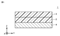
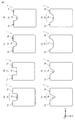
- FIG. 1 It is a schematic cross-sectional view which shows the polarizing plate by one Embodiment of this invention. It is the schematic which shows an example of the 1st laminated body. It is the schematic which shows an example of a 2nd laminated body and an end mill. It is the schematic which shows an example of a cutting process. It is the schematic for demonstrating the measurement sample in an Example. It is the schematic sectional drawing which shows the 1st laminated body in an Example. It is a schematic top view which shows the polarizing plate in an Example.
- the TOF-SIMS analysis result and the edge observation result of Example 1 are shown.
- the TOF-SIMS analysis result and the edge observation result of Comparative Example 1 are shown.
- the TOF-SIMS analysis result and the edge observation result of Comparative Example 2 are shown.
- the polarizer is a resin film containing boric acid and iodine.
- the resin film containing boric acid and iodine may be, for example, a resin film in which iodine is adsorbed and oriented on a uniaxially stretched polyvinyl alcohol-based resin film, and polyvinyl alcohol molecular chains are crosslinked with boric acid.
- the polarizer is an absorption type polarizer having a property of absorbing linearly polarized light having a vibration plane parallel to the absorption axis and transmitting linearly polarized light having a vibration plane orthogonal to the absorption axis (parallel to the transmission axis). be able to.
- the polarizer can be used as a polarizing plate by adhering an optical film on one side or both sides with an adhesive, an adhesive, or the like.
- the polarizing element 2 can form the polarizing plate 1 by being arranged between the first optical film 3 and the second optical film 4.
- the first optical film and the second optical film may be collectively referred to as an optical film.
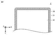
- the polarizer has a boric acid low concentration portion having a boric acid concentration lower than the boric acid concentration in the inner region (hereinafter, also referred to as the inner region) 500 ⁇ m or more inside from the end portion. It is formed. In the inner region, both the concentration of boric acid and the concentration of iodine can be substantially uniform. As shown in FIG. 2, the polarizer 2 can have a boric acid low concentration portion 30 in a region including an end portion in a plan view, and can have an inner region 32 inside 500 ⁇ m or more from the end portion.
- the inner region 32 can include an region for displaying an image when incorporated in a liquid crystal display device.
- the boric acid concentration in the intermediate region 31 between the boric acid low concentration portion 30 and the inner region 32 is usually substantially the same as the boric acid concentration in the inner region 32.
- the plan view means the view from the thickness direction of the polarizer.
- the concentration of boric acid is the concentration of boric acid per unit area including the thickness direction of the polarizer.
- TOF-SIMS time-of-flight secondary ion mass spectrometry method
- boric acid includes, for example, a boric acid molecule (H 3 BO 3 ) and a borate ion (BO 3 3- ).
- Polarizers tend to be more likely to suppress the occurrence of cracks in the dew condensation heat shock test due to the formation of low boric acid concentration sites.
- the condensation heat shock test can be performed according to the method described in the column of Examples described later.
- the concentration of boric acid in the boric acid low concentration site is preferably close to the end in the direction from the inside to the end in the plan view of the polarizer from the viewpoint of suppressing cracks and making color loss less noticeable in the appearance of the polarizer. It is so low.
- the ends of the polarizer preferably do not contain boric acid.
- the length from the end of the boric acid low concentration site may be, for example, 15 ⁇ m or more, preferably 15 ⁇ m or more and less than 200 ⁇ m, more preferably 15 ⁇ m or more and less than 150 ⁇ m, and further preferably 15 ⁇ m or more and less than 100 ⁇ m from the viewpoint of crack suppression. Particularly preferably, it may be 15 ⁇ m or more and less than 50 ⁇ m.
- the boundary between the region where the low boric acid concentration site is formed and the other region is from the end obtained by the time-of-flight secondary ion mass spectrometry (TOF-SIMS) described in the column of Examples described later. It can be obtained from the boric acid concentration profile with respect to the distance. For example, when a region where the borate ionic strength is constant can be read in the boric acid concentration profile, the average value of the borate ionic strength in that region is obtained, and the position where the borate ionic strength becomes the above average value from the end. Can be a boric acid low concentration site.
- the average borate ionic strength in the range of 30 ⁇ m inward from the point where the borate ionic strength is maximized in the borate concentration profile can be obtained, and the boric acid low concentration portion can be set from the end portion to the position where the borate ionic strength becomes the above average value.
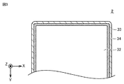
- an iodine low concentration portion having an iodine concentration lower than the iodine concentration in the inner region 500 ⁇ m or more inside from the end portion is formed in the region including the end portion.
- the length from the end of the iodine low concentration portion is 19 ⁇ m or more and 100 ⁇ m or less.
- the polarizer 2 has an iodine low concentration portion 33 in a region including an end portion in a plan view.
- the iodine concentration in the intermediate region 34 between the iodine low concentration portion 33 and the inner region 32 is usually substantially the same as the iodine concentration in the inner region 32.
- the iodine low concentration region is a region formed in a region through which light is transmitted in a plan view observation of a polarizer using an optical microscope.
- the iodine for example, molecular iodine (I 2), polyiodine complex (I 3 -, I 5 - ) - contains iodine ions (I).
- the low iodine concentration part When the length from the end of the low iodine concentration part is 100 ⁇ m or less, the low iodine concentration part tends to be inconspicuous in the appearance of the polarizer. Further, when the length from the end of the iodine low concentration portion is 19 ⁇ m or more, cracks tend to be easily suppressed.
- the length from the end of the iodine low concentration portion is preferably 19 ⁇ m or more and 50 ⁇ m or less from the viewpoint of making iodine loss less noticeable.
- the iodine low concentration site and the iodine high concentration site are discriminated according to the method described in the column of Examples described later.
- the brightness of the iodine low concentration region is usually 180 or more
- the inner region is 100 or more and 140 or less
- the iodine low concentration region and the internal region is usually less than 180.
- the boric acid low concentration site and the iodine low concentration site may be sites that partially overlap each other, or one of them may be a site that completely overlaps the other. From the viewpoint of suppressing cracks and making iodine loss less noticeable, the iodine low concentration site preferably completely contains the boric acid low concentration site.
- a plurality of boric acid low concentration sites and iodine low concentration sites may be formed in a plurality of regions of the polarizer.
- the boric acid low concentration site and the iodine low concentration site are preferably formed along the outer edge of the polarizer from the viewpoint of crack suppression.
- the boric acid low concentration site and the iodine low concentration site may be formed along the entire outer edge portion of the polarizer, or may be formed along a part of the outer edge portion of the polarizer.
- the polarizer may have a deformed portion.
- the deformed portion may be a concave portion formed on the outer edge portion and a through hole formed in the polarizer surface in the plan view of the polarizer.
- the deformed portion may have a shape in which the directions of tangent lines are discontinuous, for example, two straight lines intersect, and the radius of curvature at the intersection may be 0 mm.
- the directions of the tangents are discontinuous or the radius of curvature at the intersection is small (usually 3 mm or less, preferably 2 mm or less, more preferably 1 mm or less), the effect of preventing cracks by the present invention is remarkable.
- the polarizer may have two or more variants in the outer edge and / or in-plane. As specific examples of the shape and the position of the deformed portion, the example of the shape of the deformed portion and the position of the deformed portion in the description of the polarizing plate described later is applied.
- a boric acid low concentration portion and an iodine low concentration portion are preferably formed in the end region contained in the deformed portion from the viewpoint of suppressing cracks and making the iodine low concentration portion less noticeable.
- a polarizer having a deformed portion tends to concentrate stress on the deformed portion and easily cracks. Since the boric acid low concentration portion is formed in the end region included in the deformed portion, the occurrence of cracks tends to be easily suppressed in the dew condensation heat shock test. Further, as shown in FIG.
- the polarizing plate 21 having a polarizing element having a deformed portion includes a camera hole 22, a cover glass 24, an adhesive layer 25, a liquid crystal panel 23, a polarizing plate 26, a camera 27, and a light-shielding tape.
- the image display device 20 having 28 since the circled portion in FIG. 4 is directly visible, the iodine low formed in a wide region at the end included in the deformed portion of the polarizer 21. The concentration site becomes conspicuous, and as a result, the design may be deteriorated.
- the polarizer of the present invention is used in an image display device having a camera hole as described above, the iodine low concentration portion is inconspicuous and tends to be excellent in design.
- the deformed portion is a concave portion
- it is preferably formed so that the depth direction of the concave portion and the absorption axis (stretching direction) are orthogonal to each other, for example, from the viewpoint of crack suppression. Further, it may be formed so as to intersect at an angle of 30 degrees or more and usually 60 degrees or less.
- the polarizer may be in the shape of a long strip or in the shape of a single leaf.
- the overall shape of the polarizing element may be square or rounded in a plan view.
- the rounded square shape means a shape in which one or more of the corners of the square are curved, that is, one or more of the corners of the square is rounded, and the square shape is four. It shall mean a shape in which none of the corners are rounded. Further, in the present specification, the square shape means a rectangular shape or a square shape.
- the polarizing plate has a rounded corner shape, one or more of the four corners of the polarizing plate may have rounded corners.
- the polarizer may have a polygonal, circular, or elliptical overall shape in plan view.
- the overall shape of the polarizer in a plan view the example of the overall shape of the polarizing plate in the description of the polarizing plate described later is applied.
- the thickness of the polarizer may be, for example, 1 ⁇ m or more and 50 ⁇ m or less, and may be 3 ⁇ m or more and 15 ⁇ m or less.
- the thinner the polarizer the easier it is to suppress the contraction or expansion of the polarizer itself due to the temperature change, and the easier it is to suppress the change in the dimensions of the polarizer itself. As a result, stress is less likely to act on the polarizer, and cracks in the polarizer tend to be suppressed more easily.
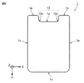
- FIG. 5 shows the overall shape of the polarizer 2 in a plan view.
- the polarizer 2 has a square shape with rounded corners as a whole, and has a concave portion as a deformed portion.
- the concave portion is formed so that the depth direction and the absorption axis (stretching direction) are parallel to each other.
- the region I (11) and the region II (12) are partially formed along a part of the outer circumference including the concave portion, and are formed on the outer edge portion including the concave portion.
- Region I (11) is a region in which both a boric acid low concentration site and an iodine low concentration site are formed.
- Region II (12) can be a region in which either a boric acid low concentration site or an iodine low concentration site is formed.
- the polarizing plate according to another aspect of the present invention is a polarizing plate including the above-mentioned polarizing element and optical films provided on one side or both sides thereof.
- the optical film can be attached to the polarizer via an adhesive or an adhesive layer made of an adhesive.
- the polarizing plate 1 is a film-shaped polarizing element 2 located between at least a pair of optical films (3, 4) and a pair of optical films (3, 4). To be equipped with.
- the polarizing plate 1 composed of the polarizing element 2 and the pair of optical films (3, 4) will be mainly described.
- the number of optical films included in the polarizing plate is not limited to two.
- the optical film means a film-like member (excluding the polarizer 2 itself) that constitutes the polarizing plate 1.
- optical film implies a protective film and a release film.
- Each optical film does not have to have a specific optical function by itself.
- the "film” (optical film) may be paraphrased as the "layer” (optical layer).
- Each pair of optical films (3, 4) contains a resin.
- the composition of each of the optical films (3, 4) is not limited.
- the polarizer 2 directly or indirectly overlaps with the optical films (3, 4), respectively.
- the polarizer 2 may overlap the optical films (3, 4) with the adhesive layer.
- FIG. 6 is a top view showing the surface of the polarizing plate 1 according to the present embodiment.
- the cross section of the polarizing plate 1 shown in FIG. 6 is perpendicular to the surface of the polarizing plate 1. Further, the cross section of the polarizing plate 1 is orthogonal to the outer circumference 1p of the polarizing plate 1 located inside the recess 13 formed in the polarizing plate 1.
- the recess 13 is formed on the outer peripheral 1p of the polarizing plate 1. That is, there is a recess 13 on the outer circumference 1p of the polarizing plate 1.
- the recess 13 may be paraphrased as a recess, a cut or a notch.
- the recess 13 may penetrate the polarizing plate 1 in a direction (Z-axis direction) perpendicular to the surface (light receiving surface) of the polarizing plate 1.
- the outer circumference 1p of the polarizing plate 1 may be rephrased as the outer edge or contour of the polarizing plate 1 (light receiving surface) viewed from a direction (planar viewing direction) perpendicular to the light receiving surface of the polarizing plate 1.
- the inner corner 13c of the recess 13 may be a right angle or a curved line when viewed from above. That is, the end face of the polarizing plate 1 located at the inner corner 13c of the recess 13 may be a curved surface. That is, the inner corner 13c of the recess may be chamfered. Since the inner corner 13c of the recess 13 is curved in a top view, cracks in the inner corner 13c of the recess 13 are more likely to be suppressed as compared with the case where the concave portion 13 is at a right angle. As shown in FIG. 4, the corners located at both ends of the recess 13 and the corners located at the four corners of the polarizing plate 1 may also be chamfered.
- the width of the recess 13 (the width of the recess 13 in the X-axis direction) is not particularly limited, but may be, for example, 3 mm or more and 160 mm or less.
- the depth of the recess 13 (width of the recess 13 in the Y-axis direction) is not particularly limited, but may be, for example, 0.5 mm or more and 160 mm or less.
- the length of the side (short side) of the polarizing plate 1 on which the recess 13 is formed is not particularly limited, but may be, for example, 30 mm or more and 90 mm or less.
- the length of the side (long side) of the polarizing plate 1 in which the recess 13 is not formed is not particularly limited, but may be, for example, 30 mm or more and 170 mm or less.
- the thickness of the entire polarizing plate 1 is not particularly limited, but may be, for example, 30 ⁇ m or more and 300 ⁇ m or less.
- the recess 13 shown in FIG. 6 has a rectangular shape (rectangular shape) with rounded corners.
- the shape of the recess 13 is not limited.
- the recess 13 may be square.
- the recess 13 may be a polygon other than a quadrangle and a triangle.
- the shape of the concave portion 13 is a rectangular shape with rounded corners, a rectangular shape, a semicircular shape, a V shape, a shape in which a straight line and a curved line are combined, and a curved shape. It may be.
- the shapes of the polarizing plates 1 shown in FIGS. 7A to 7 have symmetry, but the shape of the polarizing plate 1 may be asymmetrical.
- a plurality of recesses 13 may be formed on the outer circumference 1p of the polarizing plate 1.
- a plurality of recesses 13 may be formed on one side constituting the outer peripheral 1p of the polarizing plate 1.
- the recess 13 may be formed by cutting out at least one of the four corners of the rectangular polarizing plate 1.
- the overall shape of the polarizing plate 1 excluding the recess 13 is substantially quadrangular (rectangular).
- the shape of the polarizing plate 1 is not limited.
- the shape of the polarizing plate 1 may be square.
- the shape of the polarizing plate 1 may be a polygon other than a quadrangle, a circle, or an ellipse.
- the overall shapes of the polarizer 2 and the optical films (3, 4) may be substantially the same as the shape of the polarizing plate 1.
- the recess 13 is formed on the short side of the polarizing plate 1, but the recess 13 may be formed on the long side of the polarizing plate 1.
- the polarizer 1 may have a through hole in the plane in a plan view.
- the diameter of the through hole may be, for example, 0.5 mm or more and 30 mm or less, preferably 1 mm or more and 10 mm or less.
- the polarizing plate may further include another optical film containing a resin in addition to the pair of optical films composed of the first optical film and the second optical film. That is, the polarizing plate may include three or more optical films.
- the polarizing plate has a polarizing element 2 located between the first optical film 3 and the second optical film 4, the first optical film 3 and the second optical film 4, and a first.
- a third optical film 15 that overlaps the optical film 3 may be provided.
- the third optical film 15 may be superposed on the first optical film 3 via the adhesive layer described above.
- the resin contained in the third optical film 15 may be at least one of the above-mentioned resins listed as the resin contained in each of the first optical film 3 and the second optical film 4.
- the composition of the third optical film 15 may be the same as the composition of the first optical film 3.
- the composition of the third optical film 15 may be different from the composition of the first optical film 3.
- the composition of the third optical film 15 may be the same as the composition of the second optical film 4.
- the composition of the third optical film 15 may be different from the composition of the second optical film 4.
- the thickness of the third optical film 15 may be, for example, 5 ⁇ m or more and 200 ⁇ m or less.
- the third optical film 15 may be peeled off and removed from the polarizing plate in the manufacturing process of the image display device. That is, the third optical film 15 may be a temporary optical film.
- the polarizing plate may further include an adhesive layer that overlaps one of the pair of optical films and a release film that overlaps the adhesive layer.
- the polarizing plate shown in FIG. 9 may further include an adhesive layer that overlaps the second optical film 4 and a release film that overlaps the adhesive layer.
- the adhesive layer may contain, for example, a pressure-sensitive adhesive such as an acrylic pressure-sensitive adhesive, a rubber-based pressure-sensitive adhesive, a silicone-based pressure-sensitive adhesive, or a urethane-based pressure-sensitive adhesive.
- the thickness of the adhesive layer may be, for example, 2 ⁇ m or more and 100 ⁇ m or less.
- the resin contained in the release film may be at least one of the above-mentioned resins listed as the resin contained in each of the first optical film 3 and the second optical film 4.
- the composition of the release film may be the same as the composition of the first optical film 3.
- the composition of the release film may be different from the composition of the first optical film 3.
- the composition of the release film may be the same as the composition of the second optical film 4.
- the composition of the release film may be different from the composition of the second optical film 4.
- the thickness of the release film may be, for example, 10 ⁇ m or more and 100 ⁇ m or less.
- the release film may be peeled off and removed from the polarizing plate in the manufacturing process of the image display device.
- the release film may be arranged on both sides of the polarizing plate via the adhesive layer.
- the polarizing plate may be a reflective polarizing film, a film with an antiglare function, a film with a surface antireflection function, a reflection film, a transflective reflective film, a viewing angle compensation film, a window film, an antistatic layer, or a hard coat. It may further include at least one selected from the group consisting of a layer, an optical compensation layer, a touch sensor layer, and an antifouling layer.
- the polarizing plate can have a deformed portion in a plan view. Further, the polarizing plate may be square or rounded in a plan view.
- the optical film may be a translucent thermoplastic resin.
- the optical film may be an optically transparent thermoplastic resin.
- the resin constituting the optical film is, for example, a chain polyolefin resin, a cyclic olefin polymer resin (COP resin), a cellulose ester resin, a polyester resin, a polycarbonate resin, a (meth) acrylic resin, or a polystyrene resin. , Or a mixture or copolymer thereof.
- the composition of the first optical film may be exactly the same as the composition of the second optical film.
- both the first optical film and the second optical film may contain a cyclic olefin polymer-based resin (COP-based resin).
- COP-based resin cyclic olefin polymer-based resin
- the composition of the first optical film may be different from the composition of the second optical film.
- the glass transition temperature of the first optical film and the second optical film is preferably 100 ° C. or higher and 200 ° C. or lower, or 120 ° C. or higher and 150 ° C. or lower.
- the glass transition temperature of each of the first optical film and the second optical film is in the above range, the first optical film and the second optical film are fused to each other by the heat generated by polishing the edge of each optical film. easy.
- the chain polyolefin resin may be, for example, a homopolymer of a chain olefin such as a polyethylene resin or a polypropylene resin.
- the chain polyolefin resin may be a copolymer composed of two or more kinds of chain olefins.
- the cyclic olefin polymer resin may be, for example, a ring-opening (co) polymer of cyclic olefin or an addition polymer of cyclic olefin.
- the cyclic olefin polymer-based resin may be, for example, a copolymer of a cyclic olefin and a chain olefin (for example, a random copolymer).
- the chain olefin constituting the copolymer may be, for example, ethylene or propylene.
- the cyclic olefin polymer resin may be a graft polymer obtained by modifying the above polymer with an unsaturated carboxylic acid or a derivative thereof, or a hydride thereof.
- the cyclic olefin polymer-based resin may be, for example, a norbornene-based resin using a norbornene-based monomer such as norbornene or a polycyclic norbornene-based monomer.
- the cellulosic ester resin may be, for example, cellulose triacetate (triacetyl cellulose (TAC)), cellulose diacetate, cellulose tripropionate or cellulose dipropionate. These copolymers may be used. A cellulosic ester resin in which a part of the hydroxyl group is modified with another substituent may be used.
- TAC triacetyl cellulose
- a cellulosic ester resin in which a part of the hydroxyl group is modified with another substituent may be used.
- a polyester resin other than the cellulose ester resin may be used.
- the polyester resin may be, for example, a polycondensate of a polyvalent carboxylic acid or a derivative thereof and a polyhydric alcohol.
- the polyvalent carboxylic acid or a derivative thereof may be a dicarboxylic acid or a derivative thereof.
- the polyvalent carboxylic acid or a derivative thereof may be, for example, terephthalic acid, isophthalic acid, dimethyl terephthalate, or dimethyl naphthalenedicarboxylic acid.
- the polyhydric alcohol may be, for example, a diol.
- the polyhydric alcohol may be, for example, ethylene glycol, propanediol, butanediol, neopentyl glycol, or cyclohexanedimethanol.
- the polyester resin may be, for example, polyethylene terephthalate, polybutylene terephthalate, polyethylene naphthalate, polybutylene naphthalate, polytrimethylene terephthalate, polytrimethylene naphthalate, polycyclohexanedimethylterephthalate, or polycyclohexanedimethylnaphthalate. ..
- Polycarbonate-based resin is a polymer in which polymerization units (monomers) are bonded via carbonate groups.
- the polycarbonate-based resin may be a modified polycarbonate having a modified polymer skeleton, or may be a copolymerized polycarbonate.
- the (meth) acrylic resin is, for example, a poly (meth) acrylic acid ester (for example, polymethyl methacrylate (PMMA)); a methyl methacrylate- (meth) acrylic acid copolymer; a methyl methacrylate- (meth) acrylic.
- a poly (meth) acrylic acid ester for example, polymethyl methacrylate (PMMA)
- PMMA polymethyl methacrylate
- a methyl methacrylate- (meth) acrylic acid copolymer for example, a methyl methacrylate- (meth) acrylic.
- Acid ester copolymer Methyl methacrylate-acrylic acid ester- (meth) acrylic acid copolymer; (meth) methyl acrylate-styrene copolymer (for example, MS resin); methyl methacrylate and alicyclic hydrocarbon It may be a copolymer with a compound having a group (for example, methyl methacrylate-cyclohexyl methacrylate copolymer, methyl methacrylate- (meth) acrylate norbornyl copolymer, etc.).
- the first optical film or the second optical film is at least one selected from the group consisting of lubricants, plasticizers, dispersants, heat stabilizers, ultraviolet absorbers, infrared absorbers, antistatic agents, and antioxidants. Additives may be included.
- the thickness of the first optical film may be, for example, 5 ⁇ m or more and 90 ⁇ m or less, or 10 ⁇ m or more and 60 ⁇ m or less.
- the thickness of the second optical film may also be, for example, 5 ⁇ m or more and 90 ⁇ m or less, or 10 ⁇ m or more and 60 ⁇ m or less.
- At least one of the first optical film and the second optical film may be a film having an optical function.
- the film having an optical function may be, for example, a retardation film or a brightness improving film. For example, by stretching a film made of the above-mentioned thermoplastic resin or forming a liquid crystal layer or the like on the film, a retardation film to which an arbitrary retardation value is given can be obtained.
- the first optical film may be superposed on the polarizer via an adhesive layer.
- the second optical film may also be overlaid on the polarizer via an adhesive layer.
- the adhesive layer may contain an aqueous adhesive such as polyvinyl alcohol.
- the adhesive layer may contain an active energy ray-curable resin described later.
- the active energy ray-curable resin is a resin that cures when irradiated with active energy rays.
- the active energy ray may be, for example, ultraviolet light, visible light, electron beam, or X-ray.
- the active energy ray-curable resin may be an ultraviolet curable resin.
- the active energy ray-curable resin may be a kind of resin and may contain a plurality of kinds of resins.
- the active energy ray-curable resin may contain a cationically polymerizable curable compound or a radically polymerizable curable compound.
- the active energy ray-curable resin may contain a cationic polymerization initiator or a radical polymerization initiator for initiating the curing reaction of the curable compound.
- the cationically polymerizable curable compound may be, for example, an epoxy compound (a compound having at least one epoxy group in the molecule) or an oxetane compound (a compound having at least one oxetane ring in the molecule).
- the radically polymerizable curable compound may be, for example, a (meth) acrylic compound (a compound having at least one (meth) acryloyloxy group in the molecule).
- the radically polymerizable curable compound may be a vinyl compound having a radically polymerizable double bond.
- the active energy ray-curable resin can be used as a cationic polymerization accelerator, an ion trapping agent, an antioxidant, a chain transfer agent, a tackifier, a thermoplastic resin, a filler, a flow conditioner, a plasticizer, and a defoaming agent, if necessary. It may contain agents, antistatic agents, leveling agents, solvents and the like.
- the binder and / or the bonding surface of the optical film is subjected to corona treatment, flame treatment, plasma treatment, and ultraviolet rays.
- Surface treatment such as irradiation treatment, primer coating treatment, and saponification treatment may be performed.
- the polarizing plate is formed by laminating a front plate, a retardation film (for example, a layer giving a retardation of ⁇ / 2, a layer giving a retardation of ⁇ / 4, a positive C layer, and a combination of at least two layers selected from these.
- a retardation film for example, a layer giving a retardation of ⁇ / 2, a layer giving a retardation of ⁇ / 4, a positive C layer, and a combination of at least two layers selected from these.
- the layer obtained by the above) a protective film, a touch sensor panel, an adhesive layer and the like may be further provided.
- the polarizing plate can also be used as a circular polarizing plate by laminating layers that give a phase difference of ⁇ / 4.
- the polarizing plate may be a polarizing plate with an adhesive layer.
- the method for producing a polarizing plate is a method for producing a polarizing plate having a polarizing element, which is a resin film containing boric acid and iodine, and an optical film arranged on one side or both sides of the polarizing element.
- This is a production method including a base treatment step in which a basic solution having a temperature of 50 ° C. or lower is brought into contact with the edge of a resin film containing polarized light and iodine within 6 minutes.
- a polarizer manufacturing step (manufacturing step of a resin film containing boric acid and iodine), a lamination step, a molding step, and a cutting step, which will be described later, are further performed in this order.
- a resin film containing boric acid and iodine (hereinafter, also referred to as an unbasic-treated polarizer) can be produced, for example, by subjecting a polyvinyl alcohol-based resin film (PVA film) to a stretching treatment, a dyeing treatment, and a cross-linking treatment. it can.
- the stretching treatment, the dyeing treatment and the cross-linking treatment can be carried out by known methods.
- the PVA film is stretched in the uniaxial direction or the biaxial direction.
- the bicolor ratio of the uniaxially stretched polarizer tends to be high.
- the PVA film is dyed with iodine, a dichroic dye (polyiodine) or an organic dye using a dye solution.
- the staining solution may contain boric acid, zinc sulfate, or zinc chloride.
- the PVA film may be washed with water before dyeing. Washing with water removes stains and anti-blocking agents from the surface of the PVA film. Further, as a result of the PVA film swelling due to washing with water, dyeing spots (non-uniform dyeing) are likely to be suppressed.
- the dyed PVA film is treated with a solution of a cross-linking agent containing boric acid (eg, an aqueous solution of boric acid) for cross-linking. After treatment with a cross-linking agent, the PVA film is washed with water and then dried. Through the above procedure, a resin film containing boric acid and iodine can be obtained.
- the polyvinyl alcohol (PVA) -based resin is obtained by saponifying a polyvinyl acetate-based resin.
- the polyvinyl acetate-based resin may be, for example, polyvinyl acetate, which is a homopolymer of vinyl acetate, or a copolymer of vinyl acetate and another monomer (for example, an ethylene-vinyl acetate copolymer). ..
- Other monomers copolymerizing with vinyl acetate may be unsaturated carboxylic acids, olefins, vinyl ethers, unsaturated sulfonic acids, or acrylamides having an ammonium group, in addition to ethylene.
- the polyvinyl alcohol-based resin may be modified with aldehydes.
- the modified polyvinyl alcohol-based resin may be, for example, partially formalized polyvinyl alcohol, polyvinyl acetal, or polyvinyl butyral.
- the polyvinyl alcohol-based resin may be a polyene-based oriented film such as a dehydrated product of polyvinyl alcohol or a dehydrochlorinated product of polyvinyl chloride. Staining may be performed before stretching, or stretching may be performed in a dyeing solution.
- the length of the stretched resin film may be, for example, 3 to 7 times the length before stretching.
- the polyvinyl alcohol-based resin film may be in the shape of a long strip or in the shape of a single leaf.
- the unbase-treated polarizer and the optical film are laminated and bonded to each other to prepare a first laminated body.
- the unbase-treated polarizer and the optical film may be in the shape of a long strip.
- the unbase-treated polarizers are stacked so as to be arranged between the pair of optical films, as shown in FIG. 10, in the first laminated body 10, the unbase-treated polarizer 7 is a pair of optical films (5). , 9).
- the optical film can be attached to the polarizer via an adhesive layer.
- an adhesive layer can be formed on the outermost surface of any one of the first laminated bodies 10.
- a pressure-sensitive adhesive is applied to the surface of one of the pair of optical films (5, 9) opposite to the unbase-treated polarizing element 7, to form a pressure-sensitive adhesive layer, and the pressure-sensitive adhesive layer is adhered onto the pressure-sensitive adhesive layer. It can be formed by laminating a separate film that can be peeled off from the agent layer. Further, in the laminating step, a protective film that can be peeled off from the optical film can be bonded to the outermost surface of any one of the first laminated bodies 10.
- the size of the first laminated body 10 may be adjusted to a size that is easy to process. Further, a deformed portion may be formed on the outer edge portion of the first laminated body 10 by punching or cutting.
- the cutting and / or punching process can be performed by using a cutting blade, using a punching blade, or irradiating with a laser beam.
- the laser light may be a CO 2 laser.
- the long first laminated body can be made into a single-wafered first laminated body in the molding step. In the molding step, the first laminated body can be cut or punched alone or in a state where a plurality of laminated bodies are stacked.
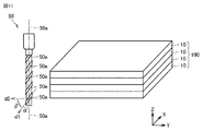
- the method for manufacturing a polarizing plate can further include a cutting step in which the end mill is brought into contact with the outer periphery of the first laminated body or the second laminated body described later, and the end mill is moved along the outer periphery of the laminated body.
- the positions of the ends of the unbase-treated polarizing element 7 and the optical films (5, 9) may be aligned with each other over the entire outer circumference of the first laminated body 10 before the cutting step.
- the end mill 50 used in the cutting process has a blade (edge) 50e protruding on a side surface substantially parallel to the rotation axis 50a.
- the side surface of the end mill 50 is brought into contact with the outer circumference (end face) of the first laminated body 10, and the rotating end mill 50 is moved along the outer circumference of the first laminated body 10.
- the rotating end mill 50 may be moved along the path indicated by the arrow in FIG.
- the outer circumference (end face) of the first laminated body 10 is cut or polished by the blade 50e, the outer circumference (end face) of the first laminated body 10 becomes smooth, the concave portion 13 is formed, and the inside of the concave portion 13 is formed.
- the corners are chamfered.
- the side surface of the end mill 50 is brought into contact with the outer periphery (end face) of the second laminated body 100 and rotated.
- the end mill 50 may be moved along the outer circumference of the second laminated body 100. That is, in the cutting step, the outer circumferences of the plurality of first laminated bodies 10 constituting the second laminated body 100 may be collectively cut or polished by the end mill 50.
- the corners located at both ends of the concave portion 13 and the corners located at the four corners of the first laminated body 10 may be chamfered.
- the cutting amount of the end mill in the cutting step may be, for example, 10 ⁇ m or more and 500 ⁇ m or less, preferably 50 ⁇ m or more and 150 ⁇ m or less.
- the cutting process may be repeated three or more times.
- chips generated in the second cutting step may be removed from the end face of the first laminated body 10 with almost no cutting of the first laminated body 10.
- a plurality of end mills may be used in each cutting process.
- the feed rate of the end mill in the cutting process may be 100 mm / min or more and less than 3000 mm / min.
- the rotation speed of the end mill in the cutting step may be, for example, 500 rpm or more and 60,000 rpm or less, preferably 10,000 rpm or more and 60,000 rpm or less.
- the cutting angle in the cutting step may be, for example, 30 ° or more and 70 ° or less, preferably 45 ° or more and 65 ° or less.
- the cutting angle ⁇ is defined as 90 ° ⁇ . As shown in FIG.
- the twist angle ⁇ of the end mill 50 is an angle formed by the direction d1 in which the blade 50e extends on the side surface of the end mill 50 and the rotation axis 50a of the end mill 50.
- the cutting angle ⁇ may be rephrased as the angle formed by the direction d1 in which the blade 50e extends and the direction d2 perpendicular to the rotation axis 50a.
- the diameter ⁇ (thickness) of the end mill 50 used in the cutting step may be, for example, 3.0 mm or more and 6.0 mm or less.
- the base treatment can be carried out by bringing a basic solution into contact with the edge of the resin film containing boric acid and iodine contained in the first laminate.
- a boric acid low concentration portion and an iodine low concentration portion can be formed.
- the base treatment can be applied to a second laminated body in which the first laminated body is laminated, for example, 5 or more and 3000 or less.
- the number of the first laminated bodies to be stacked is preferably 7 or more, for example, 2000 or 1000.
- the basic solution used for the base treatment preferably contains water.
- the basic solution may be, for example, a solution in which a strongly basic compound is dissolved in a solvent, and is preferably an aqueous solution of the strongly basic compound.
- Strongly basic compounds preferably include sodium hydroxide and / or potassium hydroxide.
- the temperature of the basic solution that comes into contact with the edge of the resin film containing boric acid and iodine may be 50 ° C. or lower, and the optical performance deteriorates due to the disordered orientation of the polarizer in the polarizing plate (polarization degree).
- the temperature is preferably 45 ° C. or lower, more preferably 40 ° C. or lower, and usually room temperature or higher.
- the time for contacting the end of the resin film containing boric acid and iodine with the basic solution may be within 6 minutes, and the optical performance deteriorates due to the disorder of the orientation of the polarizer in the polarizing plate (polarization degree). From the viewpoint of suppressing the decrease (decrease, change in hue, etc.) and reducing the boric acid concentration, the time may be preferably 5 minutes or less, and usually more than 1 minute.
- the concentration of the basic compound in the basic solution may be, for example, 0.1 mol / liter or more and 4 mol / liter or less, preferably 1 mol / liter or more and 3 mol / liter or less, and more preferably 1.5 mol / liter or less. More than mol / liter and less than 2.5 mol / liter.
- the resin film containing boric acid and iodine can be washed with water. It is preferable to wash with water twice or more.
- the washing with water can be performed by, for example, a method of immersing the first laminate or the second laminate in a tank containing water, and / or a method of spraying water on the first laminate or the second laminate.
- the polarizing plate according to the present embodiment can be obtained.
- the above-mentioned polarizing plate can be used in an image display device.
- the image display device include a liquid crystal display device, an organic EL display device, and the like.
- the polarizing plate may be used for a polarizing plate arranged on the viewing side of the image display device, may be used for a polarizing plate arranged on the backlight side of the image display device, and may be used for the viewing side and the backlight. It may be used for both polarizing plates on the side. Since the color loss portion of the polarizing plate of the present embodiment is inconspicuous, the design is not easily impaired even when it is used on the visual side of the image display device. Therefore, the image display device is suitable as an image display device having a camera hole, for example, a mobile device such as a smartphone or a mobile phone, a personal computer, or the like.
- the polarizing plate was held at ⁇ 40 ° C. for 30 minutes to cool. Then, it was exposed to the outside air at 25 ° C. for 5 minutes. Then, it was heated to 85 ° C. and kept under 85 ° C. drying conditions for 30 minutes. Then, the mixture was cooled to 25 ° C., held for 5 minutes, and then cooled to ⁇ 40 ° C. When exposed to the outside air at 25 ° C. for 5 minutes, the surface of the polarizing plate was dew-condensed, and then heated to 85 ° C. in the dew-condensed state. The dew condensation state of the polarizing plate after holding under the drying condition of 85 ° C. was eliminated.
- the measurement sample 200 includes an optical film 201 (thickness 52 ⁇ m), an adhesive layer 202 (thickness 1 ⁇ m), a polarizer 203 (thickness 8 ⁇ m), an adhesive layer 204 (thickness 1 ⁇ m), an optical film 205 (thickness 21 ⁇ m), and an adhesive layer 206 (thickness 21 ⁇ m).
- the thickness was 20 ⁇ m) in this order.
- the ion beam is irradiated while scanning the measurement region 207 on the side surface of the measurement sample 200 in the length direction (1000 ⁇ m) to obtain a two-dimensional distribution of the signal intensity of borate ions on this side surface, and from the obtained two-dimensional distribution.
- a portion corresponding to the side surface of the polarizer was cut out, and the integrated value of the signal intensity was plotted against the length direction of the measurement sample 200 to obtain a profile of the boric acid concentration with respect to the length direction.
- the conditions for time-of-flight secondary ion mass spectrometry (TOF-SIMS) are shown below.
- TOF-SIMS time-of-flight secondary ion mass spectrometry
- the production of the first laminated body 10 will be described with reference to FIG.
- the first laminated body 10 was formed by laminating the pair of optical films 5 and 9 to the polarizer 7 via the adhesive layers 6 and 8.
- the first laminated body 10 had a rectangular shape.
- the polarizer 7 is arranged between the pair of optical films 5 and 9.
- Each of the pair of optical films 5 and 9 was composed of a cyclic olefin polymer-based resin.
- the polarizer 7 was a stretched and dyed film-like polyvinyl alcohol.
- An adhesive was applied to the optical film 9 side of the first laminated body 10 to form an adhesive layer 41, and a separate film 42 was bonded onto the adhesive layer 41. This separate film was removable from the pressure-sensitive adhesive layer.
- a protective film 43 was attached to the optical film 5 side of the first laminated body 10. The protective film 43 could be peeled off from the optical film 5.
- the thickness of the optical film 5 bonded to one surface of the polarizer was 52 ⁇ m.
- the thickness of the optical film 9 bonded to the other surface of the polarizer was 21 ⁇ m.
- the thickness of the polarizer 7 was 8 ⁇ m.
- the total thickness of the first laminated body 10 was 103 ⁇ m.
- the adhesive layer 6 interposed between the optical film 5 having a thickness of 52 ⁇ m and the polarizer 7 was a polyvinyl alcohol-based resin (water glue).
- the adhesive layer 8 interposed between the optical film 9 having a thickness of 21 ⁇ m and the polarizer 7 was a UV-curable epoxy resin.
- the rotating end mill is moved to the outer circumference (recess) of the second laminate while the second laminate is fixed with a clamp and the side surface of the end mill is in contact with the outer circumference (end face) of the second laminate. It was moved along the outer circumference including. That is, the entire outer circumference of each of the 47 first laminated bodies was cut together with an end mill.
- the end mill used in each cutting process was DXL-4 manufactured by NS TOOL Co., Ltd.
- the cutting angle ⁇ was a value shown in Table 1 below.
- the diameter ⁇ of the end mill was 4 mm.
- the amount of shaving in the first cutting process was the value shown in Table 1 below.
- the rotation speed (R) of the end mill in the first cutting step was 30,000 rpm.
- the feed rate (V) of the end mill in the first cutting step was 1000 mm / min.
- the amount of shaving in the second cutting process was the value shown in Table 1 below.
- the rotation speed (R) of the end mill in the second cutting step was 30,000 rpm.
- the feed rate (V) of the end mill in the second cutting step was 1000 mm / min.
- the amount of shaving in the third cutting process was the value shown in Table 1 below.
- the rotation speed (R) of the end mill in the third cutting step was 30,000 rpm.
- the feed rate (V) of the end mill in the third cutting step was 1000 mm / min.
- FIG. 15 shows the shape of the obtained polarizing plate 110 in a plan view.
- the polarizing plate 110 had a rectangular concave portion 113 formed on the short side.
- the length of the short side of the polarizing plate 110 was 70 mm.
- the length of the long side of the polarizing plate 110 was 140 mm.
- the width 111 of the concave portion 113 was 30 mm.
- the depth 112 of the concave portion 113 was 5 mm. Further, the depth direction of the concave portion 113 was parallel to the absorption axis (stretching direction).
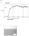
- Example 1 The polarizing plate of Example 1 was obtained by laminating 10 polarizing plates processed into the above shape and performing end base treatment under the following conditions and procedures. (1) It was immersed in an aqueous NaOH solution at a concentration of 2 mol / liter and 40 ° C. for 5 minutes. (2) Next, the laminated polarizing plates were washed in the order of water washing tank 1 (20 ° C.) and water washing tank 2 (20 ° C.) for 1 minute each. After the above-mentioned end base treatment, boric acid concentration was measured and a dew condensation heat shock test was performed on three polarizing plates. The results are shown in Table 1. In addition, FIG.
- FIG. 16 shows the TOF-SIMS analysis result (a) and the optical microscope observation image (b) of the end region.
- a boric acid low concentration portion was formed in a region including the end portion with a width of 20 ⁇ m from the end portion.
- a low iodine concentration portion was also formed in a region including the end portion with a width of 50 ⁇ m from the end portion.
- FIG. 17 shows the TOF-SIMS analysis result (a) and the optical microscope observation image (b) of the end region.
- a boric acid low concentration portion was formed in a region including the end portion with a width of 12 ⁇ m from the end portion. Further, in this polarizing plate, a low iodine concentration site was not formed in the region including the end portion.
- FIG. 18 shows the TOF-SIMS analysis result (a) and the optical microscope observation image (b) of the end region.
- a boric acid low concentration portion was formed in a region including the end portion with a width of 14 ⁇ m from the end portion.
- a low iodine concentration portion was also formed in a region including the end portion with a width of 18 ⁇ m from the end portion.
- Example 1 the number of cracks was small, the average crack length and the maximum crack length were short, and the region where the low iodine concentration site was formed was very small.
- Comparative Example 1 the number of cracks was large, the average crack length and the maximum crack length were long, and the occurrence of cracks was not suppressed.
- Comparative Example 2 although the number of cracks was reduced, the average crack length and the maximum crack length were long, and the cracks were not sufficiently suppressed. According to the present invention, it can be seen that in the above-mentioned dew condensation heat shock test, a polarizer in which the generation of cracks is suppressed and iodine loss is inconspicuous can be obtained.
Landscapes
- Physics & Mathematics (AREA)
- General Physics & Mathematics (AREA)
- Optics & Photonics (AREA)
- Nonlinear Science (AREA)
- Mathematical Physics (AREA)
- Chemical & Material Sciences (AREA)
- Crystallography & Structural Chemistry (AREA)
- Polarising Elements (AREA)
- Liquid Crystal (AREA)
Priority Applications (2)
| Application Number | Priority Date | Filing Date | Title |
|---|---|---|---|
| KR1020227008162A KR20220059947A (ko) | 2019-09-12 | 2020-08-06 | 편광자 |
| CN202080059828.8A CN114286956B (zh) | 2019-09-12 | 2020-08-06 | 偏振片 |
Applications Claiming Priority (2)
| Application Number | Priority Date | Filing Date | Title |
|---|---|---|---|
| JP2019-166290 | 2019-09-12 | ||
| JP2019166290A JP7610920B2 (ja) | 2019-09-12 | 2019-09-12 | 偏光子 |
Publications (1)
| Publication Number | Publication Date |
|---|---|
| WO2021049217A1 true WO2021049217A1 (ja) | 2021-03-18 |
Family
ID=74863989
Family Applications (1)
| Application Number | Title | Priority Date | Filing Date |
|---|---|---|---|
| PCT/JP2020/030139 Ceased WO2021049217A1 (ja) | 2019-09-12 | 2020-08-06 | 偏光子 |
Country Status (5)
| Country | Link |
|---|---|
| JP (2) | JP7610920B2 (https=) |
| KR (1) | KR20220059947A (https=) |
| CN (1) | CN114286956B (https=) |
| TW (1) | TWI881996B (https=) |
| WO (1) | WO2021049217A1 (https=) |
Cited By (1)
| Publication number | Priority date | Publication date | Assignee | Title |
|---|---|---|---|---|
| JP2023038613A (ja) * | 2021-09-07 | 2023-03-17 | 住友化学株式会社 | 偏光板、及び偏光板の製造方法 |
Families Citing this family (1)
| Publication number | Priority date | Publication date | Assignee | Title |
|---|---|---|---|---|
| WO2022191246A1 (ja) * | 2021-03-11 | 2022-09-15 | 住友化学株式会社 | 偏光板およびその製造方法 |
Citations (8)
| Publication number | Priority date | Publication date | Assignee | Title |
|---|---|---|---|---|
| JP2015094906A (ja) * | 2013-11-14 | 2015-05-18 | 日東電工株式会社 | 偏光膜および偏光膜の製造方法 |
| JP2016151603A (ja) * | 2015-02-16 | 2016-08-22 | 日東電工株式会社 | 偏光子、偏光板および画像表示装置 |
| JP2016206641A (ja) * | 2015-04-17 | 2016-12-08 | 日東電工株式会社 | 偏光子、偏光板および偏光子の製造方法 |
| JP2017058519A (ja) * | 2015-09-16 | 2017-03-23 | 日東電工株式会社 | 粘着剤層付偏光フィルム、光学部材、及び画像表示装置 |
| JP2018025798A (ja) * | 2016-08-08 | 2018-02-15 | 東友ファインケム株式会社Dongwoo Fine−Chem Co., Ltd. | 偏光板及びその製造方法 |
| WO2018139358A1 (ja) * | 2017-01-27 | 2018-08-02 | 住友化学株式会社 | 偏光板及び画像表示装置 |
| WO2018159376A1 (ja) * | 2017-02-28 | 2018-09-07 | 日東電工株式会社 | 偏光板および偏光板の製造方法 |
| JP2019148744A (ja) * | 2018-02-28 | 2019-09-05 | 日東電工株式会社 | 偏光板およびその製造方法 |
Family Cites Families (11)
| Publication number | Priority date | Publication date | Assignee | Title |
|---|---|---|---|---|
| JP4483329B2 (ja) * | 2004-02-16 | 2010-06-16 | 住友化学株式会社 | 偏光フィルムの製造方法 |
| JP5257645B2 (ja) * | 2007-10-25 | 2013-08-07 | 住友化学株式会社 | 偏光フィルムの製造方法および偏光板の製造方法 |
| JP5382843B2 (ja) * | 2007-10-31 | 2014-01-08 | 住友化学株式会社 | 偏光板の製造方法 |
| JP2009237096A (ja) * | 2008-03-26 | 2009-10-15 | Sumitomo Chemical Co Ltd | 偏光フィルムの製造方法、並びに偏光板および光学積層体 |
| JP5548444B2 (ja) * | 2009-12-29 | 2014-07-16 | 住友化学株式会社 | 偏光板の製造方法 |
| JP5555601B2 (ja) * | 2010-10-20 | 2014-07-23 | 日東電工株式会社 | 光学フィルムの製造方法、光学フィルムおよび光学フィルムの製造装置 |
| JP6181111B2 (ja) * | 2014-06-27 | 2017-08-16 | 日東電工株式会社 | 長尺状の粘着フィルムの製造方法 |
| WO2017047510A1 (ja) * | 2015-09-16 | 2017-03-23 | シャープ株式会社 | 異形状偏光板の製造方法 |
| CN108919544A (zh) | 2018-06-26 | 2018-11-30 | Oppo广东移动通信有限公司 | 显示屏组件、电子设备及电子设备的制作方法 |
| CN108900672B (zh) | 2018-07-06 | 2021-05-04 | Oppo广东移动通信有限公司 | 电子设备及电子设备的制作方法 |
| WO2020137839A1 (ja) * | 2018-12-25 | 2020-07-02 | 日東電工株式会社 | 偏光子、および、その製造方法 |
-
2019
- 2019-09-12 JP JP2019166290A patent/JP7610920B2/ja active Active
-
2020
- 2020-08-06 KR KR1020227008162A patent/KR20220059947A/ko not_active Ceased
- 2020-08-06 CN CN202080059828.8A patent/CN114286956B/zh active Active
- 2020-08-06 WO PCT/JP2020/030139 patent/WO2021049217A1/ja not_active Ceased
- 2020-08-13 TW TW109127554A patent/TWI881996B/zh active
-
2023
- 2023-11-29 JP JP2023201324A patent/JP7654054B2/ja active Active
Patent Citations (8)
| Publication number | Priority date | Publication date | Assignee | Title |
|---|---|---|---|---|
| JP2015094906A (ja) * | 2013-11-14 | 2015-05-18 | 日東電工株式会社 | 偏光膜および偏光膜の製造方法 |
| JP2016151603A (ja) * | 2015-02-16 | 2016-08-22 | 日東電工株式会社 | 偏光子、偏光板および画像表示装置 |
| JP2016206641A (ja) * | 2015-04-17 | 2016-12-08 | 日東電工株式会社 | 偏光子、偏光板および偏光子の製造方法 |
| JP2017058519A (ja) * | 2015-09-16 | 2017-03-23 | 日東電工株式会社 | 粘着剤層付偏光フィルム、光学部材、及び画像表示装置 |
| JP2018025798A (ja) * | 2016-08-08 | 2018-02-15 | 東友ファインケム株式会社Dongwoo Fine−Chem Co., Ltd. | 偏光板及びその製造方法 |
| WO2018139358A1 (ja) * | 2017-01-27 | 2018-08-02 | 住友化学株式会社 | 偏光板及び画像表示装置 |
| WO2018159376A1 (ja) * | 2017-02-28 | 2018-09-07 | 日東電工株式会社 | 偏光板および偏光板の製造方法 |
| JP2019148744A (ja) * | 2018-02-28 | 2019-09-05 | 日東電工株式会社 | 偏光板およびその製造方法 |
Cited By (2)
| Publication number | Priority date | Publication date | Assignee | Title |
|---|---|---|---|---|
| JP2023038613A (ja) * | 2021-09-07 | 2023-03-17 | 住友化学株式会社 | 偏光板、及び偏光板の製造方法 |
| JP7751419B2 (ja) | 2021-09-07 | 2025-10-08 | 住友化学株式会社 | 偏光板、及び偏光板の製造方法 |
Also Published As
| Publication number | Publication date |
|---|---|
| TWI881996B (zh) | 2025-05-01 |
| KR20220059947A (ko) | 2022-05-10 |
| JP2021043370A (ja) | 2021-03-18 |
| JP2024009307A (ja) | 2024-01-19 |
| CN114286956A (zh) | 2022-04-05 |
| TW202116886A (zh) | 2021-05-01 |
| JP7610920B2 (ja) | 2025-01-09 |
| JP7654054B2 (ja) | 2025-03-31 |
| CN114286956B (zh) | 2024-12-13 |
Similar Documents
| Publication | Publication Date | Title |
|---|---|---|
| KR101949112B1 (ko) | 편광판 | |
| JP7702993B2 (ja) | 偏光板 | |
| KR102901203B1 (ko) | 편광판 및 화상 표시 장치 | |
| JP7654054B2 (ja) | 偏光子 | |
| CN111465657A (zh) | 固化性组合物、光学层叠体及图像显示装置 | |
| JP7512236B2 (ja) | 偏光板 | |
| JP2018005252A (ja) | 偏光板及び画像表示装置 | |
| WO2021029172A1 (ja) | 偏光板 | |
| KR102836265B1 (ko) | 편광판 | |
| JP7256149B2 (ja) | 偏光板、画像表示装置及び偏光板の製造方法 | |
| TWI920034B (zh) | 偏光板、圖像顯示裝置及偏光板之製造方法 | |
| KR20230156723A (ko) | 편광판 및 그의 제조 방법 |
Legal Events
| Date | Code | Title | Description |
|---|---|---|---|
| 121 | Ep: the epo has been informed by wipo that ep was designated in this application |
Ref document number: 20862252 Country of ref document: EP Kind code of ref document: A1 |
|
| ENP | Entry into the national phase |
Ref document number: 20227008162 Country of ref document: KR Kind code of ref document: A |
|
| NENP | Non-entry into the national phase |
Ref country code: DE |
|
| 122 | Ep: pct application non-entry in european phase |
Ref document number: 20862252 Country of ref document: EP Kind code of ref document: A1 |