WO2021048898A1 - 室外ユニットおよび冷凍サイクル装置 - Google Patents
室外ユニットおよび冷凍サイクル装置 Download PDFInfo
- Publication number
- WO2021048898A1 WO2021048898A1 PCT/JP2019/035370 JP2019035370W WO2021048898A1 WO 2021048898 A1 WO2021048898 A1 WO 2021048898A1 JP 2019035370 W JP2019035370 W JP 2019035370W WO 2021048898 A1 WO2021048898 A1 WO 2021048898A1
- Authority
- WO
- WIPO (PCT)
- Prior art keywords
- refrigerant
- flow path
- passage
- valve
- compressor
- Prior art date
- Legal status (The legal status is an assumption and is not a legal conclusion. Google has not performed a legal analysis and makes no representation as to the accuracy of the status listed.)
- Ceased
Links
Images


Classifications
-
- F—MECHANICAL ENGINEERING; LIGHTING; HEATING; WEAPONS; BLASTING
- F25—REFRIGERATION OR COOLING; COMBINED HEATING AND REFRIGERATION SYSTEMS; HEAT PUMP SYSTEMS; MANUFACTURE OR STORAGE OF ICE; LIQUEFACTION SOLIDIFICATION OF GASES
- F25B—REFRIGERATION MACHINES, PLANTS OR SYSTEMS; COMBINED HEATING AND REFRIGERATION SYSTEMS; HEAT PUMP SYSTEMS
- F25B1/00—Compression machines, plants or systems with non-reversible cycle
-
- F—MECHANICAL ENGINEERING; LIGHTING; HEATING; WEAPONS; BLASTING
- F25—REFRIGERATION OR COOLING; COMBINED HEATING AND REFRIGERATION SYSTEMS; HEAT PUMP SYSTEMS; MANUFACTURE OR STORAGE OF ICE; LIQUEFACTION SOLIDIFICATION OF GASES
- F25B—REFRIGERATION MACHINES, PLANTS OR SYSTEMS; COMBINED HEATING AND REFRIGERATION SYSTEMS; HEAT PUMP SYSTEMS
- F25B40/00—Subcoolers, desuperheaters or superheaters
- F25B40/02—Subcoolers
-
- F—MECHANICAL ENGINEERING; LIGHTING; HEATING; WEAPONS; BLASTING
- F25—REFRIGERATION OR COOLING; COMBINED HEATING AND REFRIGERATION SYSTEMS; HEAT PUMP SYSTEMS; MANUFACTURE OR STORAGE OF ICE; LIQUEFACTION SOLIDIFICATION OF GASES
- F25B—REFRIGERATION MACHINES, PLANTS OR SYSTEMS; COMBINED HEATING AND REFRIGERATION SYSTEMS; HEAT PUMP SYSTEMS
- F25B41/00—Fluid-circulation arrangements
- F25B41/30—Expansion means; Dispositions thereof
- F25B41/39—Dispositions with two or more expansion means arranged in series, i.e. multi-stage expansion, on a refrigerant line leading to the same evaporator
-
- F—MECHANICAL ENGINEERING; LIGHTING; HEATING; WEAPONS; BLASTING
- F25—REFRIGERATION OR COOLING; COMBINED HEATING AND REFRIGERATION SYSTEMS; HEAT PUMP SYSTEMS; MANUFACTURE OR STORAGE OF ICE; LIQUEFACTION SOLIDIFICATION OF GASES
- F25B—REFRIGERATION MACHINES, PLANTS OR SYSTEMS; COMBINED HEATING AND REFRIGERATION SYSTEMS; HEAT PUMP SYSTEMS
- F25B2400/00—Component parts or details not otherwise provided for in this subclass
- F25B2400/13—Economisers
-
- F—MECHANICAL ENGINEERING; LIGHTING; HEATING; WEAPONS; BLASTING
- F25—REFRIGERATION OR COOLING; COMBINED HEATING AND REFRIGERATION SYSTEMS; HEAT PUMP SYSTEMS; MANUFACTURE OR STORAGE OF ICE; LIQUEFACTION SOLIDIFICATION OF GASES
- F25B—REFRIGERATION MACHINES, PLANTS OR SYSTEMS; COMBINED HEATING AND REFRIGERATION SYSTEMS; HEAT PUMP SYSTEMS
- F25B2700/00—Sensing or detecting of parameters; Sensors therefor
- F25B2700/19—Pressures
- F25B2700/193—Pressures of the compressor
- F25B2700/1931—Discharge pressures
-
- F—MECHANICAL ENGINEERING; LIGHTING; HEATING; WEAPONS; BLASTING
- F25—REFRIGERATION OR COOLING; COMBINED HEATING AND REFRIGERATION SYSTEMS; HEAT PUMP SYSTEMS; MANUFACTURE OR STORAGE OF ICE; LIQUEFACTION SOLIDIFICATION OF GASES
- F25B—REFRIGERATION MACHINES, PLANTS OR SYSTEMS; COMBINED HEATING AND REFRIGERATION SYSTEMS; HEAT PUMP SYSTEMS
- F25B2700/00—Sensing or detecting of parameters; Sensors therefor
- F25B2700/19—Pressures
- F25B2700/193—Pressures of the compressor
- F25B2700/1933—Suction pressures
-
- F—MECHANICAL ENGINEERING; LIGHTING; HEATING; WEAPONS; BLASTING
- F25—REFRIGERATION OR COOLING; COMBINED HEATING AND REFRIGERATION SYSTEMS; HEAT PUMP SYSTEMS; MANUFACTURE OR STORAGE OF ICE; LIQUEFACTION SOLIDIFICATION OF GASES
- F25B—REFRIGERATION MACHINES, PLANTS OR SYSTEMS; COMBINED HEATING AND REFRIGERATION SYSTEMS; HEAT PUMP SYSTEMS
- F25B2700/00—Sensing or detecting of parameters; Sensors therefor
- F25B2700/21—Temperatures
- F25B2700/2103—Temperatures near a heat exchanger
-
- F—MECHANICAL ENGINEERING; LIGHTING; HEATING; WEAPONS; BLASTING
- F25—REFRIGERATION OR COOLING; COMBINED HEATING AND REFRIGERATION SYSTEMS; HEAT PUMP SYSTEMS; MANUFACTURE OR STORAGE OF ICE; LIQUEFACTION SOLIDIFICATION OF GASES
- F25B—REFRIGERATION MACHINES, PLANTS OR SYSTEMS; COMBINED HEATING AND REFRIGERATION SYSTEMS; HEAT PUMP SYSTEMS
- F25B2700/00—Sensing or detecting of parameters; Sensors therefor
- F25B2700/21—Temperatures
- F25B2700/2115—Temperatures of a compressor or the drive means therefor
- F25B2700/21151—Temperatures of a compressor or the drive means therefor at the suction side of the compressor
-
- F—MECHANICAL ENGINEERING; LIGHTING; HEATING; WEAPONS; BLASTING
- F25—REFRIGERATION OR COOLING; COMBINED HEATING AND REFRIGERATION SYSTEMS; HEAT PUMP SYSTEMS; MANUFACTURE OR STORAGE OF ICE; LIQUEFACTION SOLIDIFICATION OF GASES
- F25B—REFRIGERATION MACHINES, PLANTS OR SYSTEMS; COMBINED HEATING AND REFRIGERATION SYSTEMS; HEAT PUMP SYSTEMS
- F25B2700/00—Sensing or detecting of parameters; Sensors therefor
- F25B2700/21—Temperatures
- F25B2700/2115—Temperatures of a compressor or the drive means therefor
- F25B2700/21152—Temperatures of a compressor or the drive means therefor at the discharge side of the compressor
-
- F—MECHANICAL ENGINEERING; LIGHTING; HEATING; WEAPONS; BLASTING
- F25—REFRIGERATION OR COOLING; COMBINED HEATING AND REFRIGERATION SYSTEMS; HEAT PUMP SYSTEMS; MANUFACTURE OR STORAGE OF ICE; LIQUEFACTION SOLIDIFICATION OF GASES
- F25B—REFRIGERATION MACHINES, PLANTS OR SYSTEMS; COMBINED HEATING AND REFRIGERATION SYSTEMS; HEAT PUMP SYSTEMS
- F25B2700/00—Sensing or detecting of parameters; Sensors therefor
- F25B2700/21—Temperatures
- F25B2700/2116—Temperatures of a condenser
- F25B2700/21163—Temperatures of a condenser of the refrigerant at the outlet of the condenser
Definitions
- the present invention relates to an outdoor unit and a refrigeration cycle device.
- Patent Document 1 discloses a refrigerating apparatus having an intermediate injection flow path and a suction injection flow path.
- a part of the refrigerant flowing from the condenser to the evaporator can be merged with the intermediate pressure refrigerant of the compressor using the intermediate injection flow path, or the suction flow path can be used by using the suction injection flow path. It is also possible to join the low-pressure refrigerant sucked into the compressor in. Therefore, when the operation efficiency is deteriorated by using the intermediate injection flow path, the discharge temperature of the compressor can be lowered by using the suction injection flow path.
- Patent Document 1 The refrigerating apparatus described in Japanese Patent Application Laid-Open No. 2014-01917 (Patent Document 1) switches the intermediate injection flow path to the suction injection flow path when it is necessary to lower the discharge temperature of the compressor. At this time, if the flow path is switched by the on-off valve during the operation of the compressor, the pressure fluctuation causes the compressor to vibrate. Therefore, in order to suppress vibration, it is necessary to switch the flow path after stopping the compressor. For this reason, it takes time to stop and restart the compressor, and it is a factor that deteriorates the operating efficiency.
- An object of the present invention is to provide an outdoor unit and a refrigeration cycle device with improved operating efficiency.
- the outdoor unit is configured to be connected to a load device including a first expansion valve and an evaporator.
- the outdoor unit has a compressor having a suction port, a discharge port, and an intermediate pressure port, a condenser, and a first passage and a second passage, and is between a refrigerant flowing through the first passage and a refrigerant flowing through the second passage.
- a heat exchanger configured to exchange heat with the second expansion valve and a second expansion valve are provided.
- the flow path from the compressor to the condenser, the first passage of the heat exchanger, and the second expansion valve forms a circulation flow path through which the refrigerant circulates together with the load device.
- the outdoor unit is arranged in the first refrigerant flow path and the first refrigerant flow path, in which the refrigerant flows from the portion between the outlet of the first passage and the second expansion valve of the circulation flow path to the inlet of the second passage.
- a flow path switching unit capable of selecting either a suction port or an intermediate pressure port as the destination.
- the flow path switching unit includes a first on-off valve provided between the outlet of the second passage and the intermediate pressure port, and a decompression device and a second pressure reducing device arranged in series between the outlet of the second passage and the suction port. Including on-off valve.
- the outdoor unit of the present disclosure and the refrigerating cycle device and the refrigerating machine provided with the outdoor unit, it is possible to switch the injection flow path without stopping the compressor, so that the operating efficiency of the refrigerating cycle can be improved. it can.
- FIG. 5 is an overall configuration diagram of a refrigeration cycle device according to the first embodiment. It is a figure which showed the various sensors and the control device arranged in the refrigeration cycle apparatus 1 shown in FIG. It is a flowchart for demonstrating the control of the flow path switching part 74. It is a flowchart for demonstrating control at the time of a pump down operation. It is a flowchart for demonstrating control at the time of oil recovery operation. It is a figure which shows the structure of the refrigeration cycle apparatus of Embodiment 2. It is a flowchart for demonstrating the control of the flow path switching part 74A. It is a figure which shows the structure of the refrigerating cycle apparatus 201 of the modification 1. It is a figure which shows the structure of the refrigerating cycle apparatus 201A of the modification 2. It is a figure which shows the structure of the refrigerating cycle apparatus 201B of the modification 3.
- FIG. 1 is an overall configuration diagram of a refrigeration cycle device according to the first embodiment. Note that FIG. 1 functionally shows the connection relationship and the arrangement configuration of each device in the refrigeration cycle apparatus, and does not necessarily show the arrangement in the physical space.
- the refrigeration cycle device 1 includes an outdoor unit 2, a load device 3, and extension pipes 84 and 88.
- the outdoor unit 2 is an outdoor unit of the refrigeration cycle device 1 configured to be connected to the load device 3.
- the outdoor unit 2 includes a compressor 10 having a suction port G1, a discharge port G2, and an intermediate pressure port G3, a condenser 20, a fan 22, a heat exchanger 30, a second expansion valve 40, and pipes 80 to 83. , 89 and.
- the heat exchanger 30 has a first passage H1 and a second passage H2, and is configured to exchange heat between the refrigerant flowing through the first passage H1 and the refrigerant flowing through the second passage H2.
- the load device 3 includes a first expansion valve 50, an evaporator 60, and pipes 85, 86, 87.
- the evaporator 60 exchanges heat between air and the refrigerant.
- the evaporator 60 evaporates the refrigerant by endothermic heat from the air in the cooling target space.
- the first expansion valve 50 is an electronic expansion valve capable of reducing the pressure of the refrigerant.
- the first expansion valve 50 may be, for example, a temperature expansion valve that is controlled independently of the outdoor unit 2.
- the compressor 10 compresses the refrigerant sucked from the pipes 89 and 97 and discharges it to the pipe 80.
- the drive frequency of the compressor 10 can be arbitrarily changed by inverter control.
- the compressor 10 is provided with an intermediate pressure port G3, so that the refrigerant from the intermediate pressure port G3 can flow into a portion in the middle of the compression process.
- the compressor 10 is configured to adjust the rotation speed according to a control signal from the control device 100. By adjusting the rotation speed of the compressor 10, the circulation amount of the refrigerant is adjusted, and the capacity of the refrigeration cycle device 1 can be adjusted.
- Various types of compressors 10 can be adopted, and for example, scroll type, rotary type, screw type and the like can be adopted.
- the condenser 20 is configured such that a high-temperature and high-pressure gas refrigerant discharged from the compressor 10 exchanges heat (heat dissipation) with the outside air. By this heat exchange, the refrigerant is condensed and changed to a liquid phase.
- the refrigerant discharged from the compressor 10 to the pipe 80 is condensed and liquefied in the condenser 20 and flows out to the pipe 81.
- a fan 22 for sending outside air is attached to the condenser 20 in order to improve the efficiency of heat exchange. The fan 22 supplies the condenser 20 with outside air through which the refrigerant exchanges heat in the condenser 20.
- the second expansion valve 40 is an electronic expansion valve capable of reducing the pressure of the refrigerant discharged from the condenser 20.
- the refrigerant used in the refrigerant circuit of the refrigeration cycle device 1 is CO 2 , but if a state in which it is difficult to secure the degree of supercooling occurs, another refrigerant may be used.
- the case of cooling a refrigerant such as CO 2 in a supercritical state is also referred to as a condenser 20.
- the amount of decrease of the refrigerant in the supercritical state from the reference temperature is also referred to as the degree of supercooling.
- the flow path from the compressor 10 to the condenser 20, the first passage H1 of the heat exchanger 30, and the second expansion valve 40 is together with the flow path in which the first expansion valve 50 and the evaporator 60 of the load device 3 are arranged. , Form a circulation flow path through which the refrigerant circulates.
- this circulation flow path is also referred to as a "main refrigerant circuit" of the refrigeration cycle.
- the outdoor unit 2 includes a first refrigerant flow path (91 to 94) for flowing a refrigerant from a portion between the outlet of the first passage H1 and the second expansion valve 40 of the circulation flow path to the inlet of the second passage H2.
- a flow path switching unit 74 capable of selecting either the suction port G1 or the intermediate pressure port G3 as the destination of the refrigerant flowing out from the refrigerant is further provided.
- this flow path that branches from the main refrigerant circuit and sends the refrigerant to the compressor 10 via the second passage H2 is referred to as an “injection flow path” 101.
- the outdoor unit 2 is further arranged in the first refrigerant flow path and includes a liquid receiver (receiver) 73 for storing the refrigerant.
- the third expansion valve 71 is arranged between the portion between the outlet of the first passage H1 of the circulation flow path and the second expansion valve 40 and the pipes 91 and 92 between the inlet of the liquid receiver 73.
- the outdoor unit 2 further includes a flow rate adjusting valve 72 arranged between the outlet pipe 93 of the receiver 73 and the pipe 94 leading to the second passage H2, and the gas discharge port and the second passage of the receiver 73. It is provided with a gas vent passage 95 that connects to H2 and discharges the refrigerant gas in the receiver 73.
- the pipe 91 is a pipe that branches from the main refrigerant circuit and allows the refrigerant to flow into the liquid receiver 73.
- the third expansion valve 71 is an electronic expansion valve capable of reducing the refrigerant in the high pressure portion of the main refrigerant circuit to an intermediate pressure.
- the liquid receiver 73 is a container capable of separating gas and liquid in the container from the decompressed and two-phase refrigerant, storing the refrigerant, and adjusting the amount of the refrigerant in the main refrigerant circuit.
- the gas vent passage 95 connected to the upper part of the receiver 73 and the pipe 93 connected to the lower part of the receiver 73 are in a state where the refrigerant separated into the gas refrigerant and the liquid refrigerant is separated in the receiver 73. It is a pipe for taking out.
- the flow rate adjusting valve 72 can adjust the amount of refrigerant in the liquid receiver 73 by adjusting the amount of circulating liquid refrigerant discharged from the pipe 93.
- the liquid receiver 73 By providing the liquid receiver 73 in the injection flow path in this way, it becomes easy to secure the degree of supercooling in the pipes 82 and 83 which are the liquid pipes. This is because the receiver 73 generally has a gas refrigerant, so that the refrigerant temperature becomes the saturation temperature. Therefore, if the receiver 73 is arranged in the pipe 82, the degree of supercooling cannot be ensured.
- the heat exchanger 30 exchanges heat between the refrigerant flowing through the first passage H1 which is a part of the main refrigerant circuit and the refrigerant flowing through the second passage H2 which is a part of the injection flow path 101.
- the intermediate pressure liquid refrigerant can be stored inside the receiver 73 even when the pressure in the high pressure portion of the main refrigerant circuit is high and the refrigerant is in a supercritical state. It will be possible. Therefore, the design pressure of the container of the receiver 73 can be made lower than that of the high-pressure portion, and the cost can be reduced by thinning the container.
- FIG. 2 is a diagram showing various sensors and control devices arranged in the refrigeration cycle device 1 shown in FIG. With reference to FIG. 2, the outdoor unit 2 further includes pressure sensors 110 to 113, temperature sensors 120 to 125, and a control device 100 that controls the flow path switching unit 74.
- the pressure sensor 110 detects the pressure PL of the suction port portion of the compressor 10 and outputs the detected value to the control device 100.
- the pressure sensor 111 detects the discharge pressure PH of the compressor 10 and outputs the detected value to the control device 100.
- the pressure sensor 112 detects the pressure P1 of the pipe 83 at the outlet of the second expansion valve 40, and outputs the detected value to the control device 100. Further, the pressure sensor 113 detects the intermediate pressure PM of the pipe 92 after the third expansion valve 71, and outputs the detected value to the control device 100.
- the outdoor unit 2 can reduce the refrigerant pressure to or less than the design pressure (for example, 4 MPa) of the load device 3 and then deliver the refrigerant to the load device 3.
- the design pressure for example, 4 MPa
- a general-purpose product having the same design pressure as the conventional one can be used as the load device 3.
- the temperature sensor 120 detects the discharge temperature TH of the compressor 10 and outputs the detected value to the control device 100.
- the temperature sensor 121 detects the refrigerant temperature T1 of the pipe 81 at the outlet of the condenser 20, and outputs the detected value to the control device 100.
- the temperature sensor 122 detects the refrigerant temperature T2 at the outlet of the first passage H1 on the cooled side of the heat exchanger 30 and outputs the detected value to the control device 100.
- the temperature sensor 123 detects the ambient temperature TA of the outdoor unit 2 and outputs the detected value to the control device 100.
- the temperature sensor 125 detects the temperature at the outlet of the second passage H2 of the heat exchanger 30 and outputs the detected value to the control device 100.
- the temperature sensor 124 detects the temperature TL of the suction pipe of the compressor 10 and outputs the detected value to the control device 100.
- the second refrigerant flow path includes a pipe 96 that connects the outlet of the second passage H2 of the heat exchanger 30 and the flow path switching portion 74, and the flow path switching portion 74.
- the flow path switching unit 74 includes pipes 97 and 98 in which the pipe 96 is branched into two, a pressure reducing device 77 arranged between the pipes 97 and 98, and on-off valves 75 and 76 arranged in the pipes 97 and 98, respectively. Including.
- the on-off valve 75 is provided between the outlet of the second passage H2 and the intermediate pressure port G3.
- the pressure reducing device 77 and the on-off valve 76 are arranged in series between the outlet of the second passage H2 and the suction port G1.
- the pipe 97 is connected between the pipe 96 and the intermediate pressure port G3.
- the on-off valve 75 and the on-off valve 76 can switch whether the injection destination of the refrigerant is the intermediate pressure port G3 of the compressor 10 or the suction port G1.
- the injection flow path 101 controls the discharge temperature TH of the compressor 10 by inflowing the two-phase refrigerant that has been decompressed into the compressor 10.
- the amount of refrigerant in the main refrigerant circuit can be adjusted by the receiver 73 installed on the injection flow path 101.
- the injection flow path 101 is also responsible for ensuring supercooling of the refrigerant in the main refrigerant circuit by heat exchange by the heat exchanger 30.
- the control device 100 switches the injection by the on-off valve 75 and the on-off valve 76 so that each purpose can be carried out under each operating condition.
- the control device 100 includes a CPU (Central Processing Unit) 102, a memory 104 (ROM (Read Only Memory) and RAM (Random Access Memory)), an input / output buffer (not shown) for inputting / outputting various signals, and the like. Consists of including.
- the CPU 102 expands the program stored in the ROM into a RAM or the like and executes the program.
- the program stored in the ROM is a program in which the processing procedure of the control device 100 is described.
- the control device 100 executes control of each device in the outdoor unit 2 according to these programs. This control is not limited to software processing, but can also be processed by dedicated hardware (electronic circuit).
- the control device 100 feedback-controls the third expansion valve 71 so that the discharge temperature TH of the compressor 10 matches the target temperature. Specifically, the control device 100 increases the opening degree of the third expansion valve 71 when the discharge temperature TH of the compressor 10 is higher than the target temperature. As a result, the amount of refrigerant flowing into the intermediate pressure port G3 or the suction port G1 via the liquid receiver 73 increases, so that the discharge temperature TH decreases.
- the control device 100 reduces the opening degree of the third expansion valve 71. As a result, the amount of refrigerant flowing into the intermediate pressure port G3 or the suction port G1 via the liquid receiver 73 is reduced, so that the discharge temperature TH rises.
- the control device 100 maintains the opening degree of the third expansion valve 71 in the current state.
- control device 100 controls the opening degree of the third expansion valve 71 so that the discharge temperature TH of the compressor 10 approaches the target temperature.
- control device 100 feedback-controls the flow rate adjusting valve 72 so that the refrigerant temperature T1 at the outlet of the condenser 20 matches the target temperature in order to secure the supercooling degree SC of the refrigerant at the outlet of the condenser 20. Specifically, when the supercooling degree SC determined by the refrigerant temperature T1 at the outlet of the condenser 20 and the pressure of the condenser 20 (approximate by PH) is larger than the target value, the control device 100 controls the flow rate adjusting valve 72. Reduce the opening.
- the supercooling degree SC is reduced.
- the control device 100 adjusts the opening degree of the flow rate adjusting valve 72. increase.
- the amount of gas refrigerant in the receiver 73 increases and the amount of liquid refrigerant decreases, so that the amount of refrigerant circulating in the main refrigerant circuit increases, the refrigerant temperature T1 decreases, and the supercooling degree SC increases.
- control device 100 maintains the opening degree of the flow rate adjusting valve 72 in the current state.
- control device 100 controls the opening degree of the flow rate adjusting valve 72 so that the refrigerant temperature T1 at the outlet of the condenser 20 approaches the target temperature.
- the control device 100 controls the compressor 10 and the second expansion valve 40 so as to use the supercritical region of the refrigerant. For example, when the outside air temperature is higher than the supercritical temperature of the refrigerant, such as in summer, the control device 100 increases the rotation speed of the compressor 10 to be higher than in spring or autumn to increase the pressure in the high pressure portion. In this case, the pressure in the high pressure portion of the main refrigerant circuit becomes high. The pressure is reduced by the second expansion valve 40 so that the load device 3 can be shared with the device normally used as a refrigerant. At this time, the second expansion valve 40 is controlled as follows.
- the control device 100 feedback-controls the second expansion valve 40 so that the pressure P1 matches the target pressure. Specifically, when the pressure P1 is higher than the target pressure, the control device 100 reduces the opening degree of the second expansion valve 40. As a result, the amount of decompression by the second expansion valve 40 increases, so that the pressure P1 decreases.
- the control device 100 increases the opening degree of the second expansion valve 40. As a result, the amount of decompression by the second expansion valve 40 is reduced, so that the pressure P1 rises.
- the control device 100 maintains the opening degree of the second expansion valve 40 in the current state.
- the pressure in the load device 3 can be set to be equal to or lower than the design pressure of the device normally used as the refrigerant, and is shared with the load device of the conventional machine using a refrigerant such as R410A. Can be used.
- the control device 100 opens the on-off valve 75 and closes the on-off valve 76 to increase the injection amount to the compressor 10 and discharge the compressor 10. Prevent further temperature rise.
- the control device 100 monitors the refrigerant temperature T2 with the temperature sensor 122 while the on-off valve 75 is open, and closes the on-off valve 75 when it detects that the degree of supercooling of the refrigerant cannot be secured. , Open the on-off valve 76. As a result, the refrigerant on the low pressure side and the refrigerant in the injection flow path 101 are merged, the intermediate pressure PM is lowered, and the temperature difference in the heat exchanger 30 can be secured.
- each device such as the receiver 73 arranged in the injection flow path 101 is depressurized by the third expansion valve 71 with respect to the main refrigerant circuit, the design pressure can be lowered, so that the manufacturing cost can be reduced. Even when the design pressure is lowered, when the pressure sensor 113 detects an increase in the intermediate pressure PM during operation due to overfilling of the refrigerant or an increase in the outside air temperature, it is safe to release the pressure to the low pressure side by opening the on-off valve 76. Measures can be taken.
- FIG. 3 is a flowchart for explaining the control of the flow path switching unit 74.
- the control device 100 determines in step S1 whether the on-off valve 75 is in the open state and the on-off valve 76 is in the closed state. If the on-off valve 75 is in the open state and the on-off valve 76 is in the closed state (YES in S1), the intermediate pressure port G3 is selected as the destination of the refrigerant flowing through the injection flow path 101. On the contrary, when the suction port G1 is selected as the destination of the refrigerant flowing through the injection flow path, the on-off valve 75 is in the closed state and the on-off valve 76 is in the open state.
- step S2 the control device 100 determines whether or not the refrigerant temperature T2 at the outlet of the first passage H1 of the heat exchanger 30 is equal to or higher than the first temperature Tth1. To judge. Thereby, it is determined whether or not the degree of supercooling of the refrigerant passing through the pipe 82 is secured.
- the control device 100 sets the intake refrigerant temperature TL to the threshold value TLth1 in step S3. Determine if it is higher than.
- the liquid refrigerant of the receiver 73 may be in a liquid back state in which the refrigerant flows into the compressor 10.
- step S3 in such a case, switching the flow path to the on-off valve 76 is stopped to prevent the liquid refrigerant from flowing into the compressor 10.
- the liquid refrigerant may be sucked into the compressor 10.
- the on-off valve 76 is controlled to remain closed when the suction of the liquid refrigerant is detected.
- the on-off valve 75 may also be closed when suction of the liquid refrigerant occurs. Whether or not the compressor 10 sucks the liquid refrigerant is determined by eliminating the degree of superheat, which is the difference between the saturation temperature in the pressure PL detected by the pressure sensor 110 and the temperature TL detected by the temperature sensor 124. it can.
- the on-off valve 76 is closed and the liquid refrigerant is sent to the compressor 10. It may be prevented from being inhaled.
- the control device 100 sequentially executes the processes of steps S4 to S5 to determine the destination of the refrigerant at the suction port.
- the flow path switching unit 74 is controlled so as to be G1.
- the control device 100 closes the on-off valve 75 in step S4, opens the on-off valve 76 in step S5, and then returns the process to the main routine in step S10.
- the pressure reducing device 77 is provided between the on-off valve 75 and the on-off valve 76, the pressure fluctuation when switching the flow path in the flow path switching unit 74 is relaxed and transmitted to the compressor 10. Therefore, since the vibration at the time of switching the flow path is reduced, the on-off valves 75 and 76 can be opened and closed without stopping the operation of the compressor 10. Therefore, the flow path can be switched in a short time, and energy loss due to stopping and restarting the compressor 10 can be avoided.
- the control device 100 When the refrigerant temperature T2 is lower than the first temperature Tth1 (NO in S2), the degree of supercooling can be secured, and when the suction refrigerant temperature TL of the compressor 10 is lower than the threshold value TLth1 (in S3). In NO), since the liquid refrigerant may be sucked into the compressor 10, the control device 100 returns the process to the main routine in step S10 without switching the flow path switching unit 74 in steps S4 to S5. ..
- the control device 100 performs steps S8 to S9 when the intake refrigerant temperature TL of the compressor 10 is lower than the threshold value TLth2 (NO in S6).
- the flow path switching unit 74 is controlled so that the treatments are sequentially executed and the destination of the refrigerant is the intermediate pressure port G3.
- the intake refrigerant temperature TL of the compressor 10 is equal to or higher than the threshold value TLth2 (YES in S6), in the control device 100, the refrigerant temperature T2 at the outlet of the first passage H1 of the heat exchanger 30 is the second temperature Tth2.
- the degree of supercooling of the refrigerant in the pipe 82 is determined based on whether or not the above is the case.
- step S7 when the refrigerant temperature T2 is lower than the second temperature Tth2 (NO in S7), the supercooling degree is secured and the on-off valve 76 is closed in step S8 in order to return to the normal injection flow path state. After the on-off valve 75 is opened in step S9, the process proceeds to step S10.
- the control device 100 controls the flow path switching unit 74 so as to increase the pressure difference, and the refrigerant is transferred from the intermediate pressure port G3 to the suction port G1. Switch the destination of. Therefore, since the amount of decompression in the third expansion valve 71 can be secured, the amount of temperature decrease in the third expansion valve 71 increases. Thereby, the temperature difference between the refrigerant temperature of the first passage H1 and the refrigerant temperature of the second passage H2 of the heat exchanger 30 can be secured. Therefore, the amount of heat exchanged by the heat exchanger 30 increases, and the refrigerant temperature T2 can be lowered.
- the pressure reducing device 77 is arranged between the on-off valve 75 and the on-off valve 76, the behavior of the compressor 10 is stable even if the flow path is switched without stopping the compressor 10, so that the switching can be performed. High speed can be achieved.
- An on-off valve 28 or the like is installed in the pipe 84 or 85 through which the liquid refrigerant flows in the main refrigerant circuit, and the compressor 10 is operated with the pipe 83 shut off to move the refrigerant from the load device 3 to the outdoor unit 2. Storage is called pump-down operation.
- the pump-down operation is performed, for example, by operating the compressor 10 after closing the second expansion valve 40 or closing the on-off valve 28 before the operation is stopped or at the time of relocation.
- the control device 100 is configured to control the compressor 10, the on-off valve 75, and the on-off valve 76.
- the control device 100 is configured to close the on-off valve 76 while operating the compressor 10 when executing a pump-down operation for collecting the refrigerant in the liquid receiver 73.
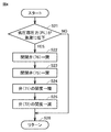
- FIG. 4 is a flowchart for explaining control during pump down operation.
- the control device 100 stops the compressor 10 to stop the pump down. ing. Since the compressor 10 is configured so that the refrigerant does not pass through in the stopped state, the refrigerant does not flow back into the load device 3. However, under certain conditions, if supercooling is prioritized, the pump down will be performed with the on-off valve 76 open, and the pressure PL may not drop completely and the outdoor unit may not stop, or the pressure after the pump down stops. The PL rises quickly, and the compressor 10 may repeatedly start and stop in a short time.
- control device 100 detects in step S21 that the pressure PL of the low pressure portion suddenly drops below the set value, the control device 100 executes the processes of steps S22 to S25, and the on-off valve at the time of pump down in the injection flow path 101. By closing 76, the bypass to high pressure or intermediate pressure can be cut off and pump down can be performed stably.
- step S22 the control device 100 closes the on-off valve 76 to block the bypass path between the load device 3 and the high-pressure unit.
- control device 100 opens the on-off valve 75 in step S23, increases the opening degree of the third expansion valve 71 in step S24, and further, in step S25, the control device 100 increases the opening degree of the flow rate adjusting valve 72. By reducing the amount of refrigerant, the amount of refrigerant stored in the receiver 73 is increased.
- the on-off valve 75 is opened during the pump-down operation, but the on-off valve 75 may be closed.
- the on-off valve 76 is closed during the pump-down operation, but when the pressure sensor 111 or 113 detects an excessive increase in pressure due to overfilling of the refrigerant or the like, the on-off valve 76 is temporarily opened. As a result, the pressure of the liquid reservoir 73 may be temporarily released to the intake side of the compressor. As a result, the compressor 10 can be stopped after recovering as much refrigerant as possible in the receiver 73 in the pump down operation.
- the outdoor unit 2 has a gas vent passage 95 provided between the outlet of the receiver 73 and the receiver 73 for discharging the refrigerant gas in the receiver 73, and the liquid in the receiver 73.
- a flow rate adjusting valve 72 arranged at the refrigerant outlet is provided.
- the outdoor unit 2 includes a control device 100 configured to control the compressor 10 and the flow rate adjusting valve 72.
- the control device 100 is configured to increase the opening degree of the third expansion valve 71 and decrease the opening degree of the flow rate adjusting valve 72 when the oil recovery condition for reducing the refrigerating machine oil in the compressor 10 is satisfied.
- FIG. 5 is a flowchart for explaining control during the oil recovery operation.
- the control device 100 determines whether or not the oil recovery condition is satisfied.
- the oil recovery condition is satisfied, for example, when the operation time elapses for a certain period of time, or when the low-speed operation of the compressor 10 continues for a certain period of time or more.
- control device 100 If the oil recovery condition is not satisfied (NO in S31), the control device 100 returns the process to the main routine once in step S35, and monitors whether the oil recovery condition is satisfied again in step S31.
- the control device 100 closes the on-off valve 76 in step S32, opens the on-off valve 75 in step S33, and opens the flow rate adjusting valve 72 in step S34. Reduce. As a result, the amount of refrigerant flowing out from the liquid refrigerant outlet from the liquid receiver 73 decreases, the amount of liquid refrigerant stored in the liquid receiver 73 increases, and the liquid refrigerant is separately stored on the liquid refrigerant from the gas vent passage 95. Refrigerant oil will flow out.
- the amount of refrigerant in the receiver 73 is increased by the pump down operation to raise the liquid level, thereby causing the liquid level side.
- the refrigerating machine oil located in can be recovered from the degassing passage 95 to the compressor 10.
- Embodiment 2 when an accumulator is installed in the main refrigerant circuit, a refrigeration cycle device that switches the circuit depending on the conditions will be described.
- FIG. 6 is a diagram showing the configuration of the refrigeration cycle device of the second embodiment.
- the refrigeration cycle device 1A shown in FIG. 6 includes an outdoor unit 2A instead of the outdoor unit 2 in the configuration of the refrigeration cycle device 1 shown in FIGS. 1 and 2. Since the load device 3 has the same configuration, the description will not be repeated. Further, since the arrangement of the pressure sensor and the temperature sensor is the same as that in FIG. 2, the description will not be repeated.
- the outdoor unit 2A includes a flow path switching unit 74A instead of the flow path switching unit 74, and further includes an accumulator 89B.
- the accumulator 89B is configured to temporarily store the refrigerant from the load device 3 toward the suction port G1 of the compressor 10 in the circulation flow path.
- the flow path switching unit 74A is an on-off valve that opens and closes the flow path connecting the outlet of the second passage H2 and the refrigerant inlet of the accumulator 89B with the pressure reducing device 77 interposed therebetween. 78 is further included.
- connection destination of the injection flow path 101 has three patterns of the intermediate pressure port G3 of the compressor 10, the suction port G1, and the pipe 89A upstream of the accumulator 89B.
- FIG. 7 is a flowchart for explaining the control of the flow path switching unit 74A.
- the control device 100 determines in step S31 whether or not the on-off valve 75 is in the open state and the on-off valves 76 and 78 are in the closed state. If the on-off valve 75 is in the open state and the on-off valves 76 and 78 are in the closed state (YES in S31), the intermediate pressure port G3 is selected as the destination of the refrigerant flowing through the injection flow path 101.
- step S32 the control device 100 determines whether or not the refrigerant temperature T2 at the outlet of the first passage H1 of the heat exchanger 30 is equal to or higher than the first temperature Tth1. To judge. Thereby, it is determined whether or not the degree of supercooling of the refrigerant passing through the pipe 82 is secured.
- the control device 100 sets the intake refrigerant temperature TL to the threshold value TLth1 in step S33. Determine if it is higher than.
- the control device 100 determines in step S34 whether the discharge temperature TH is equal to or higher than the target temperature THth1.
- the control device 100 sequentially executes the processes of steps S35 to S36 so that the destination of the refrigerant is the suction port G1. To control.
- the control device 100 closes the on-off valves 75 and 78 in step S35, opens the on-off valve 76 in step S36, and then returns the process to the main routine in step S48.
- the control device 100 sequentially executes the processes of steps S37 to S38 to switch the flow path so that the destination of the refrigerant is the pipe 89A at the inlet of the accumulator 89B.
- the unit 74A is controlled.
- the control device 100 closes the on-off valves 75 and 76 in step S37, opens the on-off valve 78 in step S38, and then returns the process to the main routine in step S48.
- the pressure reducing device 77 is provided between the on-off valve 75 and the on-off valve 76, the pressure fluctuation when switching the flow path in the flow path switching unit 74 is relaxed and transmitted to the compressor 10. Therefore, since the vibration at the time of switching the flow path is reduced, the on-off valves 75, 76, and 78 can be opened and closed without stopping the operation of the compressor 10. Therefore, the flow path can be switched in a short time, and energy loss due to stopping and restarting the compressor 10 can be avoided.
- the control device 100 When the refrigerant temperature T2 is lower than the first temperature Tth1 (NO in S32), the degree of supercooling can be secured, and when the suction refrigerant temperature TL of the compressor 10 is lower than the threshold value TLth1 (in S33). In NO), since the liquid refrigerant may be sucked into the compressor 10, the control device 100 returns the process to the main routine in step S10 without switching the flow path switching unit 74 in steps S34 to S38. ..
- the control device 100 performs steps S46 to S47 when the intake refrigerant temperature TL of the compressor 10 is lower than the threshold value TLth2 (NO in S39).
- the flow path switching unit 74 is controlled so that the processes are sequentially executed and the destination of the refrigerant is the intermediate pressure port G3.
- the control device 100 sets the refrigerant temperature T2 at the outlet of the first passage H1 of the heat exchanger 30 in step S40.
- the degree of supercooling of the refrigerant in the pipe 82 is determined based on whether or not the second temperature is Tth2 or higher. In addition, Tth1> Tth2.
- step S41 the control device 100 determines whether or not the discharge temperature TH is equal to or higher than the target temperature THth2 in step S41. In addition, THth1 ⁇ THth2.
- the control device 100 sequentially executes the processes of steps S42 to S43 so that the destination of the refrigerant is the suction port G1. To control.
- the control device 100 closes the on-off valve 78 in step S42, opens the on-off valve 76 in step S43, and then returns the process to the main routine in step S48.
- the control device 100 sequentially executes the processes of steps S44 to S45 and switches the flow path so that the destination of the refrigerant is the pipe 89A at the inlet of the accumulator 89B.
- the unit 74A is controlled.
- the control device 100 closes the on-off valve 76 in step S44, opens the on-off valve 78 in step S45, and then returns the process to the main routine in step S48.
- step S46 when the refrigerant temperature T2 is lower than the second temperature Tth2 (NO in S40), the degree of supercooling is secured, so that the on-off valves 76 and 78 are set in step S46 in order to return to the normal injection flow path state. After the on-off valve 75 is opened in the closed state and step S47, the process proceeds to step S48.
- connection destination of the injection flow path 101 is set to the accumulator 89B.
- the discharge temperature TH can be suppressed by connecting the injection flow path 101 to the suction port G1 after the accumulator 89B in a state where the degree of supercooling cannot be secured and directly feeding the cooled refrigerant.
- FIG. 8 is a diagram showing the configuration of the refrigeration cycle device 201 of the first modification.
- the refrigeration cycle device 201 has a configuration in which the connection destination of the injection flow path is only the suction port G1 alone.
- FIG. 9 is a diagram showing the configuration of the refrigeration cycle device 201A of the second modification.
- the refrigeration cycle device 201A has a configuration in which the connection destination of the injection flow path is only the pipe 89A at the inlet of the accumulator 89B.
- FIG. 10 is a diagram showing the configuration of the refrigeration cycle device 201B of the modified example 3.
- the refrigeration cycle device 201B has a configuration in which the injection flow path is connected only to the intermediate pressure port G3 alone.
- each connection destination can be configured as a single unit depending on the usage conditions of the refrigeration cycle device.
- the intermediate pressure can be sufficiently lowered. Therefore, if the degree of supercooling can always be ensured, a compressor is used as shown in FIG. It is also possible to connect only the intermediate pressure port G3 to 10. Similarly, when the use is limited to the condition that the discharge temperature does not rise, the configuration can be configured only by connecting to the pipe 89A as shown in FIG.
- the refrigeration cycle device 1 may be used as an air conditioner or the like.
- 1,1A, 201,201A, 201B Refrigeration cycle device 2,2A outdoor unit, 3 load device, 10 compressor, 20 condenser, 22 fan, 28,75,76,78 on-off valve, 30 heat exchanger, 40 2nd expansion valve, 50 1st expansion valve, 60 evaporator, 71 3rd expansion valve, 72 flow control valve, 73 receiver, 74,74A flow path switching unit, 80-85, 89, 89A, 91-94 , 96-98 piping, 77 decompression device, 84,88 extension piping, 89B accumulator, 95 degassing passage, 100 control device, 101 injection flow path, 102 CPU, 104 memory, 110-113 pressure sensor, 120-125 temperature sensor , G1 suction port, G2 discharge port, G3 intermediate pressure port, H1 first passage, H2 second passage.
Landscapes
- Engineering & Computer Science (AREA)
- Physics & Mathematics (AREA)
- Mechanical Engineering (AREA)
- Thermal Sciences (AREA)
- General Engineering & Computer Science (AREA)
- Air Conditioning Control Device (AREA)
- Compression-Type Refrigeration Machines With Reversible Cycles (AREA)
Priority Applications (4)
| Application Number | Priority Date | Filing Date | Title |
|---|---|---|---|
| JP2021544987A JP7155440B2 (ja) | 2019-09-09 | 2019-09-09 | 室外ユニットおよび冷凍サイクル装置 |
| GB2201367.6A GB2602893B (en) | 2019-09-09 | 2019-09-09 | Outdoor unit and refrigeration cycle apparatus |
| PCT/JP2019/035370 WO2021048898A1 (ja) | 2019-09-09 | 2019-09-09 | 室外ユニットおよび冷凍サイクル装置 |
| JP2022160266A JP7378561B2 (ja) | 2019-09-09 | 2022-10-04 | 室外ユニットおよび冷凍サイクル装置 |
Applications Claiming Priority (1)
| Application Number | Priority Date | Filing Date | Title |
|---|---|---|---|
| PCT/JP2019/035370 WO2021048898A1 (ja) | 2019-09-09 | 2019-09-09 | 室外ユニットおよび冷凍サイクル装置 |
Publications (1)
| Publication Number | Publication Date |
|---|---|
| WO2021048898A1 true WO2021048898A1 (ja) | 2021-03-18 |
Family
ID=74866212
Family Applications (1)
| Application Number | Title | Priority Date | Filing Date |
|---|---|---|---|
| PCT/JP2019/035370 Ceased WO2021048898A1 (ja) | 2019-09-09 | 2019-09-09 | 室外ユニットおよび冷凍サイクル装置 |
Country Status (3)
| Country | Link |
|---|---|
| JP (2) | JP7155440B2 (https=) |
| GB (1) | GB2602893B (https=) |
| WO (1) | WO2021048898A1 (https=) |
Cited By (1)
| Publication number | Priority date | Publication date | Assignee | Title |
|---|---|---|---|---|
| WO2023233452A1 (ja) * | 2022-05-30 | 2023-12-07 | 三菱電機株式会社 | 室外ユニットおよび冷凍サイクル装置 |
Families Citing this family (2)
| Publication number | Priority date | Publication date | Assignee | Title |
|---|---|---|---|---|
| JPWO2025126455A1 (https=) * | 2023-12-15 | 2025-06-19 | ||
| JP7844608B1 (ja) * | 2024-12-16 | 2026-04-13 | 日本キヤリア株式会社 | 冷凍装置、および冷凍ユニット |
Citations (7)
| Publication number | Priority date | Publication date | Assignee | Title |
|---|---|---|---|---|
| JPH04110567A (ja) * | 1990-08-31 | 1992-04-13 | Hitachi Ltd | 冷凍装置 |
| JPH10318614A (ja) * | 1997-05-16 | 1998-12-04 | Matsushita Electric Ind Co Ltd | 空気調和機 |
| JP2007263443A (ja) * | 2006-03-28 | 2007-10-11 | Mitsubishi Electric Corp | 空気調和装置 |
| JP2008039233A (ja) * | 2006-08-03 | 2008-02-21 | Daikin Ind Ltd | 冷凍装置 |
| US20110094248A1 (en) * | 2007-12-20 | 2011-04-28 | Carrier Corporation | Refrigerant System and Method of Operating the Same |
| WO2013160966A1 (ja) * | 2012-04-27 | 2013-10-31 | 三菱電機株式会社 | 空気調和装置 |
| JP2014119221A (ja) * | 2012-12-18 | 2014-06-30 | Daikin Ind Ltd | 冷凍装置 |
Family Cites Families (1)
| Publication number | Priority date | Publication date | Assignee | Title |
|---|---|---|---|---|
| JPH10104567A (ja) * | 1996-10-01 | 1998-04-24 | Seiko Instr Inc | カラー液晶表示装置 |
-
2019
- 2019-09-09 WO PCT/JP2019/035370 patent/WO2021048898A1/ja not_active Ceased
- 2019-09-09 GB GB2201367.6A patent/GB2602893B/en active Active
- 2019-09-09 JP JP2021544987A patent/JP7155440B2/ja active Active
-
2022
- 2022-10-04 JP JP2022160266A patent/JP7378561B2/ja active Active
Patent Citations (7)
| Publication number | Priority date | Publication date | Assignee | Title |
|---|---|---|---|---|
| JPH04110567A (ja) * | 1990-08-31 | 1992-04-13 | Hitachi Ltd | 冷凍装置 |
| JPH10318614A (ja) * | 1997-05-16 | 1998-12-04 | Matsushita Electric Ind Co Ltd | 空気調和機 |
| JP2007263443A (ja) * | 2006-03-28 | 2007-10-11 | Mitsubishi Electric Corp | 空気調和装置 |
| JP2008039233A (ja) * | 2006-08-03 | 2008-02-21 | Daikin Ind Ltd | 冷凍装置 |
| US20110094248A1 (en) * | 2007-12-20 | 2011-04-28 | Carrier Corporation | Refrigerant System and Method of Operating the Same |
| WO2013160966A1 (ja) * | 2012-04-27 | 2013-10-31 | 三菱電機株式会社 | 空気調和装置 |
| JP2014119221A (ja) * | 2012-12-18 | 2014-06-30 | Daikin Ind Ltd | 冷凍装置 |
Cited By (1)
| Publication number | Priority date | Publication date | Assignee | Title |
|---|---|---|---|---|
| WO2023233452A1 (ja) * | 2022-05-30 | 2023-12-07 | 三菱電機株式会社 | 室外ユニットおよび冷凍サイクル装置 |
Also Published As
| Publication number | Publication date |
|---|---|
| JP7155440B2 (ja) | 2022-10-18 |
| JPWO2021048898A1 (https=) | 2021-03-18 |
| GB2602893A (en) | 2022-07-20 |
| JP7378561B2 (ja) | 2023-11-13 |
| JP2022177312A (ja) | 2022-11-30 |
| GB2602893B (en) | 2023-05-17 |
Similar Documents
| Publication | Publication Date | Title |
|---|---|---|
| US9651288B2 (en) | Refrigeration apparatus and refrigeration cycle apparatus | |
| JP7378561B2 (ja) | 室外ユニットおよび冷凍サイクル装置 | |
| JP7150148B2 (ja) | 室外ユニット、冷凍サイクル装置および冷凍機 | |
| EP2910871B1 (en) | Refrigeration device | |
| JP2010127531A (ja) | 冷凍空調装置 | |
| WO2021210064A1 (ja) | 熱源ユニット、冷凍サイクル装置および冷凍機 | |
| JP7224480B2 (ja) | 室外ユニットおよび冷凍サイクル装置 | |
| CN114270113B (zh) | 热源机组及制冷装置 | |
| CN114364929B (zh) | 室外单元以及冷冻循环装置 | |
| TW202246713A (zh) | 冷凍裝置、冷凍裝置的控制方法及溫度控制系統 | |
| JP2013164250A (ja) | 冷凍装置 | |
| JP7282258B2 (ja) | 室外ユニットおよび冷凍サイクル装置 | |
| EP4145061B1 (en) | Refrigerating apparatus | |
| JPWO2021048898A5 (https=) | ||
| JP5927553B2 (ja) | 冷凍装置 | |
| WO2021048899A1 (ja) | 室外ユニット及び冷凍サイクル装置 | |
| JP7412639B2 (ja) | 熱源ユニット | |
| US20250369671A1 (en) | Refrigeration cycle device | |
| CN114061162A (zh) | 制冷系统及其控制方法 | |
| JP7571170B2 (ja) | 冷凍サイクル装置 | |
| WO2021048905A1 (ja) | 室外ユニットおよび冷凍サイクル装置 | |
| WO2024023993A1 (ja) | 冷凍サイクル装置 | |
| JP2022070152A (ja) | 空気調和装置 | |
| JP2009270777A (ja) | 冷凍装置 | |
| JP2007155145A (ja) | 冷凍装置 |
Legal Events
| Date | Code | Title | Description |
|---|---|---|---|
| 121 | Ep: the epo has been informed by wipo that ep was designated in this application |
Ref document number: 19945208 Country of ref document: EP Kind code of ref document: A1 |
|
| ENP | Entry into the national phase |
Ref document number: 2021544987 Country of ref document: JP Kind code of ref document: A |
|
| ENP | Entry into the national phase |
Ref document number: 202201367 Country of ref document: GB Kind code of ref document: A Free format text: PCT FILING DATE = 20190909 |
|
| WWE | Wipo information: entry into national phase |
Ref document number: 2201367.6 Country of ref document: GB |
|
| NENP | Non-entry into the national phase |
Ref country code: DE |
|
| 122 | Ep: pct application non-entry in european phase |
Ref document number: 19945208 Country of ref document: EP Kind code of ref document: A1 |
|
| WWG | Wipo information: grant in national office |
Ref document number: 2201367.6 Country of ref document: GB |