EP2910871B1 - Refrigeration device - Google Patents
Refrigeration device Download PDFInfo
- Publication number
- EP2910871B1 EP2910871B1 EP12884974.2A EP12884974A EP2910871B1 EP 2910871 B1 EP2910871 B1 EP 2910871B1 EP 12884974 A EP12884974 A EP 12884974A EP 2910871 B1 EP2910871 B1 EP 2910871B1
- Authority
- EP
- European Patent Office
- Prior art keywords
- refrigerant
- refrigerant circuit
- pressure
- compressor
- tank
- Prior art date
- Legal status (The legal status is an assumption and is not a legal conclusion. Google has not performed a legal analysis and makes no representation as to the accuracy of the status listed.)
- Active
Links
- 238000005057 refrigeration Methods 0.000 title claims description 75
- 239000003507 refrigerant Substances 0.000 claims description 372
- 239000010721 machine oil Substances 0.000 claims description 31
- 239000003921 oil Substances 0.000 claims description 31
- 230000007423 decrease Effects 0.000 claims description 5
- 239000007788 liquid Substances 0.000 description 25
- 230000002159 abnormal effect Effects 0.000 description 7
- 238000010586 diagram Methods 0.000 description 7
- 238000001816 cooling Methods 0.000 description 3
- 230000001747 exhibiting effect Effects 0.000 description 3
- 238000010438 heat treatment Methods 0.000 description 2
- 239000004215 Carbon black (E152) Substances 0.000 description 1
- 230000006835 compression Effects 0.000 description 1
- 238000007906 compression Methods 0.000 description 1
- 230000000694 effects Effects 0.000 description 1
- 229930195733 hydrocarbon Natural products 0.000 description 1
- 150000002430 hydrocarbons Chemical class 0.000 description 1
- 238000011144 upstream manufacturing Methods 0.000 description 1
Images


Classifications
-
- F—MECHANICAL ENGINEERING; LIGHTING; HEATING; WEAPONS; BLASTING
- F25—REFRIGERATION OR COOLING; COMBINED HEATING AND REFRIGERATION SYSTEMS; HEAT PUMP SYSTEMS; MANUFACTURE OR STORAGE OF ICE; LIQUEFACTION SOLIDIFICATION OF GASES
- F25B—REFRIGERATION MACHINES, PLANTS OR SYSTEMS; COMBINED HEATING AND REFRIGERATION SYSTEMS; HEAT PUMP SYSTEMS
- F25B43/00—Arrangements for separating or purifying gases or liquids; Arrangements for vaporising the residuum of liquid refrigerant, e.g. by heat
- F25B43/02—Arrangements for separating or purifying gases or liquids; Arrangements for vaporising the residuum of liquid refrigerant, e.g. by heat for separating lubricants from the refrigerant
-
- F—MECHANICAL ENGINEERING; LIGHTING; HEATING; WEAPONS; BLASTING
- F25—REFRIGERATION OR COOLING; COMBINED HEATING AND REFRIGERATION SYSTEMS; HEAT PUMP SYSTEMS; MANUFACTURE OR STORAGE OF ICE; LIQUEFACTION SOLIDIFICATION OF GASES
- F25B—REFRIGERATION MACHINES, PLANTS OR SYSTEMS; COMBINED HEATING AND REFRIGERATION SYSTEMS; HEAT PUMP SYSTEMS
- F25B31/00—Compressor arrangements
- F25B31/002—Lubrication
- F25B31/004—Lubrication oil recirculating arrangements
-
- F—MECHANICAL ENGINEERING; LIGHTING; HEATING; WEAPONS; BLASTING
- F25—REFRIGERATION OR COOLING; COMBINED HEATING AND REFRIGERATION SYSTEMS; HEAT PUMP SYSTEMS; MANUFACTURE OR STORAGE OF ICE; LIQUEFACTION SOLIDIFICATION OF GASES
- F25B—REFRIGERATION MACHINES, PLANTS OR SYSTEMS; COMBINED HEATING AND REFRIGERATION SYSTEMS; HEAT PUMP SYSTEMS
- F25B7/00—Compression machines, plants or systems, with cascade operation, i.e. with two or more circuits, the heat from the condenser of one circuit being absorbed by the evaporator of the next circuit
-
- F—MECHANICAL ENGINEERING; LIGHTING; HEATING; WEAPONS; BLASTING
- F25—REFRIGERATION OR COOLING; COMBINED HEATING AND REFRIGERATION SYSTEMS; HEAT PUMP SYSTEMS; MANUFACTURE OR STORAGE OF ICE; LIQUEFACTION SOLIDIFICATION OF GASES
- F25B—REFRIGERATION MACHINES, PLANTS OR SYSTEMS; COMBINED HEATING AND REFRIGERATION SYSTEMS; HEAT PUMP SYSTEMS
- F25B2400/00—General features or devices for refrigeration machines, plants or systems, combined heating and refrigeration systems or heat-pump systems, i.e. not limited to a particular subgroup of F25B
- F25B2400/13—Economisers
-
- F—MECHANICAL ENGINEERING; LIGHTING; HEATING; WEAPONS; BLASTING
- F25—REFRIGERATION OR COOLING; COMBINED HEATING AND REFRIGERATION SYSTEMS; HEAT PUMP SYSTEMS; MANUFACTURE OR STORAGE OF ICE; LIQUEFACTION SOLIDIFICATION OF GASES
- F25B—REFRIGERATION MACHINES, PLANTS OR SYSTEMS; COMBINED HEATING AND REFRIGERATION SYSTEMS; HEAT PUMP SYSTEMS
- F25B2400/00—General features or devices for refrigeration machines, plants or systems, combined heating and refrigeration systems or heat-pump systems, i.e. not limited to a particular subgroup of F25B
- F25B2400/16—Receivers
-
- F—MECHANICAL ENGINEERING; LIGHTING; HEATING; WEAPONS; BLASTING
- F25—REFRIGERATION OR COOLING; COMBINED HEATING AND REFRIGERATION SYSTEMS; HEAT PUMP SYSTEMS; MANUFACTURE OR STORAGE OF ICE; LIQUEFACTION SOLIDIFICATION OF GASES
- F25B—REFRIGERATION MACHINES, PLANTS OR SYSTEMS; COMBINED HEATING AND REFRIGERATION SYSTEMS; HEAT PUMP SYSTEMS
- F25B2500/00—Problems to be solved
- F25B2500/27—Problems to be solved characterised by the stop of the refrigeration cycle
-
- F—MECHANICAL ENGINEERING; LIGHTING; HEATING; WEAPONS; BLASTING
- F25—REFRIGERATION OR COOLING; COMBINED HEATING AND REFRIGERATION SYSTEMS; HEAT PUMP SYSTEMS; MANUFACTURE OR STORAGE OF ICE; LIQUEFACTION SOLIDIFICATION OF GASES
- F25B—REFRIGERATION MACHINES, PLANTS OR SYSTEMS; COMBINED HEATING AND REFRIGERATION SYSTEMS; HEAT PUMP SYSTEMS
- F25B2600/00—Control issues
- F25B2600/25—Control of valves
- F25B2600/2509—Economiser valves
-
- F—MECHANICAL ENGINEERING; LIGHTING; HEATING; WEAPONS; BLASTING
- F25—REFRIGERATION OR COOLING; COMBINED HEATING AND REFRIGERATION SYSTEMS; HEAT PUMP SYSTEMS; MANUFACTURE OR STORAGE OF ICE; LIQUEFACTION SOLIDIFICATION OF GASES
- F25B—REFRIGERATION MACHINES, PLANTS OR SYSTEMS; COMBINED HEATING AND REFRIGERATION SYSTEMS; HEAT PUMP SYSTEMS
- F25B2700/00—Sensing or detecting of parameters; Sensors therefor
- F25B2700/03—Oil level
Definitions
- the present invention relates to a refrigeration apparatus and, more particularly, to a binary refrigeration apparatus including a first refrigerant circuit having an evaporator, a second refrigerant circuit having a condenser, and a cascade condenser formed by the evaporator and the condenser.
- WO 2008/150289 A1 discloses a refrigerant system according to the preamble of claim 1, which incorporates at least two circuits arranged in a cascaded relationship.
- the upper circuit utilizes a hydrocarbon refrigerant and preferably the lower circuit utilizes CO2 refrigerant.
- the CO2 cascaded circuit mainly operates in a subcritical region.
- performance enhancement features such as, for example, an economized function provided by a flash tank or economizer heat exchanger. Additional enhancement features can also include a liquid-suction heat exchanger and bypass function.
- a binary refrigeration apparatus As a typical refrigeration apparatus, a binary refrigeration apparatus has conventionally been proposed.
- This refrigeration apparatus includes a first refrigerant circuit having an evaporator, a second refrigerant circuit having a condenser, and a cascade condenser formed by the evaporator and the condenser.
- Another binary refrigeration apparatus of this type has also been proposed in which the second refrigerant circuit is configured so that "an expansion tank 65 is connected to a pipe 20S of the compressor 20 on the suction side via a capillary tube 66, the capillary tube 66 is connected in parallel with a check valve 67, and the direction of the expansion tank 65 is defined as the forward direction of the check valve" (see Patent Literature 1).
- Such a refrigeration apparatus generally quickly collects the refrigerant in the second refrigerant circuit through a check valve during the stop of a compressor of the second refrigerant circuit in order to prevent an increase in pressure of the refrigerant in the second refrigerant circuit.
- the refrigerant gradually returns from the expansion tank to the second refrigerant circuit through a pressure reducing unit after the start of the compressor of the second refrigerant circuit in order to reduce the start load of the compressor of the second refrigerant circuit.
- Patent Literature 1 Japanese Unexamined Patent Application Publication 2007-303792 (Abstract, Fig. 6 )
- a typical binary refrigeration apparatus assume that the ambient temperature of a second refrigerant circuit is higher than the saturation temperature of the refrigerant (the saturation temperature of the refrigerant flowing through a circuit portion of the second refrigerant circuit on the high-pressure side) on the high-pressure side of the second refrigerant circuit during the operation of the refrigeration apparatus.
- the typical binary refrigeration apparatus recovers the refrigerant from the second refrigerant circuit to the expansion tank in order to prevent an increase in pressure of the refrigerant in the second refrigerant circuit, as described above.
- the refrigerant density in a circuit portion on the high-pressure side (a circuit portion from the discharge port of the compressor to the pressure reducing unit) is higher than that in a circuit portion on the low-pressure side (a circuit portion from the pressure reducing unit to the suction port of the compressor).
- the pressure in the circuit portion of the second refrigerant circuit on the high-pressure side is higher than that in the circuit portion of the second refrigerant circuit on the low-pressure side.
- the expansion tank is connected to a pipe on the suction side of the compressor of the second refrigerant circuit, that is, the circuit portion of the second refrigerant circuit on the low-pressure side. Accordingly, the typical binary refrigeration apparatus has a problem that an abnormal increase in pressure cannot be avoided in the circuit portion of the second refrigerant circuit on the high-pressure side when the compressor of the second refrigerant circuit stops.
- an on-off valve (an on-off valve that blocks traffic between the circuit portion of the second refrigerant circuit on the high-pressure side and the circuit portion of the second refrigerant circuit on the low-pressure side) for preventing the refrigerant from flowing into the evaporator at the stop of the compressor of the second refrigerant circuit is provided upstream of the evaporator of the second refrigerant circuit.
- Such an on-off valve further reduces the area of the passage through which the refrigerant flows from the circuit portion of the second refrigerant circuit on the high-pressure side into the circuit portion of the second refrigerant circuit on the low-pressure side. This often makes it impossible to avoid an abnormal increase in pressure of the refrigerant in the circuit portion of the second refrigerant circuit on the high-pressure side, so the above-described problem becomes more serious.
- the binary refrigeration apparatus even when the compressor of the second refrigerant circuit stops, operating the first refrigerant circuit to cool the second refrigerant circuit makes it possible to avoid an abnormal increase in pressure of the refrigerant in the second refrigerant circuit.
- the function of the expansion tank is disabled except for the case where the first refrigerant circuit cannot operate because of, for example, power failures.
- the typical binary refrigeration apparatus includes the expansion tank which may not be used, the cost of the binary refrigeration apparatus increases disadvantageously.
- the present invention has been made to solve at least one of the above-described problems, and has as its object to provide a refrigeration apparatus that can prevent an abnormal increase in pressure of a refrigerant in a circuit portion of a second refrigerant circuit on the high-pressure side when a compressor of the second refrigerant circuit stops.
- a refrigeration apparatus includes a first refrigerant circuit, a second refrigerant circuit, a cascade condenser, a receiver, a tank, a bypass, and a first on-off valve.
- the first refrigerant circuit includes a first compressor, a first condenser, a first pressure reducing unit, and a first evaporator that are sequentially connected to each other by pipes.
- the second refrigerant circuit includes a second compressor, a second condenser, a second pressure reducing unit, and a second evaporator that are sequentially connected to each other by pipes.
- the cascade condenser is formed by the first evaporator of the first refrigerant circuit and the second condenser of the second refrigerant circuit.
- the receiver is connected between the second condenser and the second pressure reducing unit of the second refrigerant circuit and stores an excess refrigerant.
- the tank is connected to the second compressor of the second refrigerant circuit and stores excess refrigerating machine oil in the second compressor so as to adjust an amount of refrigerating machine oil in the second compressor.
- the bypass connects the receiver and the tank to each other.
- the first on-off valve is disposed in the bypass, opens the bypass when a high-side pressure in the second refrigerant circuit increases to not less than a predetermined pressure, and closes the bypass when the high-side pressure in the second refrigerant circuit decreases to not more than the predetermined pressure.
- the refrigerant in the second refrigerant circuit flows from the receiver disposed in the circuit portion of the second refrigerant circuit on the high-pressure side through the bypass and the first on-off valve and is stored in the tank.
- the second compressor of the second refrigerant circuit stops so that the high-side pressure in the second refrigerant circuit increases to the predetermined pressure or more
- the refrigerant in the second refrigerant circuit flows from the receiver disposed in the circuit portion of the second refrigerant circuit on the high-pressure side through the bypass and the first on-off valve and is stored in the tank.
- the tank serving as an expansion tank of a typical refrigeration apparatus also serves as an oil tank of the second compressor during the operation of the second refrigerant circuit.
- the refrigeration apparatus can prevent failure of the second compressor caused by shortage of refrigerating machine oil.
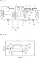
- Fig. 1 illustrates an exemplary configuration of a refrigerant circuit in a refrigeration apparatus according to Embodiment 1 of the present invention.
- a refrigeration apparatus 100 of Embodiment 1 is implemented in a binary refrigeration apparatus and includes a first refrigerant circuit 50 and a second refrigerant circuit 60.
- the first refrigerant circuit 50 serves as a refrigerant circuit in which a first refrigerant circulates, and includes a first compressor 1, a first condenser 2, a first expansion valve 3, and a first evaporator 4 that are sequentially connected to each other by pipes.
- the first compressor 1 draws by suction a low-pressure gas first refrigerant, and compresses the first refrigerant into a high-pressure gas refrigerant.
- the first condenser 2 exchanges heat between the first refrigerant compressed into a high-pressure gas refrigerant by the first compressor 1 and a heat exchange object such as air, and compresses the first refrigerant into a high-pressure liquid refrigerant.
- the first expansion valve 3 expands the first refrigerant condensed into a high-pressure liquid refrigerant in the first condenser 2 and reduces its pressure to obtain a low-pressure, two-phase gas-liquid refrigerant.
- the first evaporator 4 exchanges heat between the first refrigerant expanded and reduced in pressure into a low-pressure, two-phase gas-liquid refrigerant in the first expansion valve 3, and a second refrigerant flowing through the second condenser 7 of the second refrigerant circuit 60, and evaporates the first refrigerant into a low-pressure gas refrigerant. That is, in the refrigeration apparatus 100 of Embodiment 1, the first evaporator 4 of the first refrigerant circuit 50 and the second condenser 7 of the second refrigerant circuit 60 constitute a cascade condenser 15.
- the first expansion valve 3 corresponds to a first pressure reducing unit of the present invention.
- the first pressure reducing unit may be implemented using, for example, a capillary tube.
- the "high pressure” and “low pressure” used for the first refrigerant circuit 50 in the above description, and the “high pressure” and “low pressure” to be used for the first refrigerant circuit 50 in the following description refer to relative pressures of the first refrigerant in the first refrigerant circuit 50, and do not refer to absolute pressures of the first refrigerant.
- the second refrigerant circuit 60 serves as a refrigerant circuit in which a second refrigerant circulates, and includes a second compressor 5, a second condenser 7, a second expansion valve 10, and a second evaporator 11 that are sequentially connected to each other by pipes.
- the second compressor 5 draws by suction a low-pressure gas second refrigerant, and compresses the second refrigerant into a high-pressure gas refrigerant.
- the second condenser 7 exchanges heat between the second refrigerant compressed into a high-pressure gas refrigerant in the second compressor 5, and the first refrigerant flowing through the first evaporator 4 of the first refrigerant circuit 50, and condenses the second refrigerant into a high-pressure liquid refrigerant or a high-pressure, two-phase gas-liquid refrigerant.
- the second expansion valve 10 expands the second refrigerant condensed into a high-pressure liquid refrigerant or a high-pressure, two-phase gas-liquid refrigerant in the second condenser 7, and reduces its pressure to obtain a low-pressure, two-phase gas-liquid refrigerant.
- the second evaporator 11 exchanges heat between the second refrigerant expanded and reduced in pressure into a low-pressure, two-phase gas-liquid refrigerant in the second expansion valve 10, and a heat exchange object such as air, and evaporates the second refrigerant into a low-pressure gas refrigerant.
- the second expansion valve 10 corresponds to a second pressure reducing unit of the present invention.
- the second pressure reducing unit may be implemented using, for example, a capillary tube.
- the "high pressure” and “low pressure” used for the second refrigerant circuit 60 in the above description, and the “high pressure” and “low pressure” to be used for the second refrigerant circuit 60 in the following description refer to relative pressures of a second refrigerant in the second refrigerant circuit 60, and do not refer to absolute pressures of the second refrigerant.
- the second refrigerant circuit 60 of Embodiment 1 also includes an oil separator 6, a receiver 8, an on-off valve 9, an accumulator 12, a bypass 13, a bypass valve 13a, and a tank 14.
- the oil separator 6 is disposed between the second compressor 5 and the second condenser 7, and separates refrigerating machine oil from the second refrigerant discharged from the second compressor 5.
- the oil separator 6 includes an oil return pipe 6a.
- the oil return pipe 6a is connected to the suction port of the second compressor 5, and the refrigerating machine oil separated by the oil separator 6 returns to the suction side of the second compressor 5.
- the receiver 8 is disposed between the second condenser 7 and the second expansion valve 10, and stores an excess second refrigerant. When the two-phase gas-liquid second refrigerant flows out of the second condenser 7, the receiver 8 separates the second refrigerant into gas and liquid second refrigerants, and supplies the liquid second refrigerant to the second expansion valve 10.
- the on-off valve 9 is disposed between the receiver 8 and the second expansion valve 10, and opens and closes a circuit portion between the receiver 8 and the second expansion valve 10. That is, the on-off valve 9 prevents the second refrigerant from flowing into the second evaporator 11. More specifically, the on-off valve 9 blocks traffic between a circuit portion (a circuit portion from the discharge port of the second compressor 5 to the second expansion valve 10) of the second refrigerant circuit 60 on the high-pressure side, and a circuit portion (a circuit portion from the second expansion valve 10 to the suction port of the second compressor 5) of the second refrigerant circuit 60 on the low-pressure side.
- the on-off valve 9 corresponds to a second on-off valve of the present invention.
- the accumulator 12 is disposed between the second evaporator 11 and the second compressor 5.
- the accumulator 12 separates the second refrigerant that has flowed out of the second evaporator 11 into gas and liquid second refrigerants, and draws the gas second refrigerant by suction into the second compressor 5, thereby preventing liquid back in the second compressor 5.
- the accumulator 12 stores an excess second refrigerant.
- the second refrigerant circuit 60 of Embodiment 1 also includes the receiver 8 to store the excess second refrigerant. Thus, if there is no possibility of occurrence of liquid back in the second compressor 5, the accumulator 12 need not be provided.
- the tank 14 has the same function as that of an expansion tank of a typical refrigeration apparatus (more specifically a binary refrigeration apparatus).
- the tank 14 is connected to the receiver 8 by the bypass 13. More specifically, in the refrigeration apparatus 100 of Embodiment 1, the circuit portion of the second refrigerant circuit 60 on the high-pressure side is connected to the tank 14 serving as an expansion tank.
- the bypass 13 includes the bypass valve 13a that opens and closes the bypass 13.
- the bypass valve 13a is kept closed (the bypass 13 is kept closed) during normal operation.
- the bypass valve 13a is opened (the bypass 13 is opened).
- the bypass valve 13a corresponds to a first on-off valve of the present invention.
- the predetermined pressure refers to a pressure higher than a high-side pressure (the pressure of the refrigerant in the circuit portion of the second refrigerant circuit 60 on the high-pressure side) expected in normal operation, and a pressure lower than an allowable pressure set to prevent a failure of the second refrigerant circuit 60.
- the high-side pressure of the refrigerant in the second refrigerant circuit 60 is detected by, for example, a pressure sensor (not shown) provided in the circuit portion of the second refrigerant circuit 60 on the high-pressure side.
- the refrigeration apparatus 100 with the aforementioned configuration operates in the following manner.
- Fig. 2 is a Mollier chart showing the operating state of a refrigeration apparatus according to Embodiment 1 of the present invention.
- a low-pressure gas first refrigerant (point A) in the first refrigerant circuit 50 is drawn by suction into and compressed in the first compressor 1, transforms into a high-pressure gas refrigerant (point B) in the first refrigerant circuit 50, and is discharged from the first compressor 1.
- the first refrigerant (point B) discharged from the first compressor 1 flows into the first condenser 2, is cooled and condensed by heat exchange with an object such as air (by heating the heat exchange object such as air), and transforms into a high-pressure liquid first refrigerant (point C) in the first refrigerant circuit 50.
- the first refrigerant circuit 50 repeats the above-mentioned series of operations.
- a low-pressure gas second refrigerant (point E) in the second refrigerant circuit 60 is drawn by suction into and compressed in the second compressor 5, transforms into a high-pressure gas refrigerant (point F) in the second refrigerant circuit 60, and is discharged from the second compressor 5.
- Refrigerating machine oil is separated by the oil separator 6 from the second refrigerant (point F) discharged from the second compressor 5, and the resulting second refrigerant flows into the second condenser 7 (the cascade condenser 15), is cooled and condensed by the first refrigerant flowing through the first evaporator 4 of the first refrigerant circuit 50 (by heating the first refrigerant flowing through the first evaporator 4 of the first refrigerant circuit 50) and transforms into a high-pressure liquid second refrigerant (point G) in the second refrigerant circuit 60.
- the second refrigerant Upon flowing out of the second condenser 7, the second refrigerant flows into the second expansion valve 10 through the receiver 8 and the on-off valve 9, is expanded and reduced in pressure, and transforms into a low-pressure, two-phase gas-liquid refrigerant (point H) in the second refrigerant circuit 60. Then, the second refrigerant that has flowed out of the second expansion valve 10 is heated and evaporated by a heat exchange object such as air (by cooling the heat exchange object such as air) and transforms into a low-pressure gas first refrigerant (point E) in the second refrigerant circuit 60. Thereafter, the second refrigerant passes through the accumulator 12, and is drawn by suction into the second compressor 5 again. The second refrigerant circuit 60 repeats the above-mentioned series of operations.
- a heat exchange object such as air
- the refrigeration apparatus 100 that performs the foregoing operation uses the second evaporator 11 of the second refrigerant circuit 60 as a use-side heat exchanger, that is, the second evaporator 11 cools air in a storage space where an object to be cooled is stored, the capacity of the second evaporator 11 is the product of the enthalpy difference between points H and E and the amount of second refrigerant flowing through the second evaporator 11.
- the on-off valve 9 is opened so that the second refrigerant flows into the second evaporator 11 and the second compressor 5 is operated.
- the first refrigerant circuit is operated.
- the on-off valve 9 is closed so that the flow of second refrigerant stops, the second compressor 5 is stopped, and the first refrigerant circuit is also stopped.
- the ambient temperature of the second refrigerant circuit 60 is higher than the saturation temperature of the refrigerant (the saturation temperature of the second refrigerant flowing through the circuit portion of the second refrigerant circuit 60 on the high-pressure side) on the high-pressure side of the second refrigerant circuit 60 during operation, when the second compressor 5 of the second refrigerant circuit 60 stops, the pressure in the second refrigerant circuit 60 increases to a pressure corresponding to the ambient temperature.
- the refrigeration apparatus 100 of Embodiment 1 is assumed to use, for example, a CO 2 refrigerant as the second refrigerant. It is also assumed that the saturation temperature of the refrigerant on the high-pressure side during the operation of the second refrigerant circuit 60 is lower than a critical temperature (31.1 [degrees C]) of the CO 2 refrigerant. In such a case, the pressure of the refrigerant in the second refrigerant circuit 60 in an OFF state is illustrated in Fig. 3 .
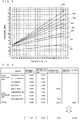
- Fig. 3 illustrates the relationship among the refrigerant density, the refrigerant temperature, and the refrigerant pressure of the second refrigerant of Embodiment 1 of the present invention.
- the abscissa indicates the temperature of the second refrigerant
- the ordinate indicates the pressure of the second refrigerant.
- the refrigerant temperature and the pressure when the refrigerant density (amount of refrigerant [kg]/volume [m 3 ]) of the second refrigerant is 150 [kg/m 3 ], 230 [kg/m 3 ], 260 [kg/m 3 ], 350 [kg/m 3 ], 400 [kg/m 3 ], 450 [kg/m 3 ], 500 [kg/m 3 ], and 550 [kg/m 3 ], respectively.
- the pressure of the second refrigerant also increases. As the refrigerant density of the second refrigerant increases, the pressure of the second refrigerant also increases. If, for example, the refrigerant density of the second refrigerant is about 350 [kg/m 3 ] and its temperature is 60 [degrees C], the pressure of the second refrigerant is 10.894 [MPa].
- the internal volume of the tank 14 is determined such that the pressure of the refrigerant in the second refrigerant circuit 60 falls within an allowable range even when the second refrigerant circuit 60 stops so that the ambient temperature of the second refrigerant circuit 60 increases and the pressure of the refrigerant in the second refrigerant circuit 60 increases.
- Fig. 4 illustrates the relationship among the internal volume of each component of the second refrigeration circuit, the amount of refrigerant (the amount of second refrigerant) stored in the component, the refrigerant density in the second refrigerant circuit, and the refrigerant pressure in the refrigeration apparatus of Embodiment 1 of the present invention.
- the amount of refrigerant stored in the component of the second refrigerant circuit 60 shown in Fig. 4 refers to the amount of refrigerant stored in the component during the operation of a second refrigerant circuit 60 exhibiting 10 horsepower.
- the "discharge pipe” illustrated in Fig. 4 refers to a pipe extending from the discharge port of the second compressor 5 to the second condenser.
- the "liquid pipe” refers to a pipe extending from the second condenser 7 to the second expansion valve 10.
- the "suction pipe” refers to a pipe extending from the second evaporator 11 to the suction port of the second compressor 5.
- the pipe extending from the second expansion valve 10 to the second evaporator 11 is short and has an internal volume and a refrigerant storage capacity, which are small and ignored in Fig. 4 .
- the total internal volume of the second refrigerant circuit 60 is 0.084 [m 3 ] and the amount of refrigerant is 19.36 [kg], and thus the refrigerant density is 230.6 [kg/m 3 ].
- the pressure of the refrigerant in the second refrigerant circuit 60 is about 7.696 [MPa], as illustrated in Fig. 2 .
- the internal volume of the expansion tank of the typical refrigeration apparatus is similarly determined.
- the refrigerant density in a circuit portion on the high-pressure side is higher than that in a circuit portion on the low-pressure side.
- the second compressor 5 of the second refrigerant circuit 60 stops so that the second refrigerant in the second refrigerant circuit 60 increases to almost the ambient temperature
- the pressure of the refrigerant in the circuit portion of the second refrigerant circuit 60 on the high-pressure side becomes higher than that in the circuit portion of the second refrigerant circuit 60 on the low-pressure side.
- the pressure of the refrigerant in the circuit portion of the second refrigerant circuit 60 on the high-pressure side is often higher than the allowable pressure of the refrigerant in the second refrigerant circuit.
- the on-off valve 9 for opening and closing a circuit portion between the receiver 8 and the second expansion valve 10 is provided, the aforementioned problem is more serious.
- the area of the passage through which the second refrigerant flows from the circuit portion of the second refrigerant circuit 60 on the high-pressure side to the circuit portion of the second refrigerant circuit 60 on the low-pressure side further decreases. This often makes it impossible to avoid an abnormal increase in pressure of the refrigerant in the circuit portion of the second refrigerant circuit 60 on the high-pressure side.
- the second refrigerant circuit 60 of Embodiment 1 has a configuration in which the tank 14 serving as an expansion tank is connected through the bypass 13 and the bypass valve 13a to the receiver 8 disposed in the circuit portion of the second refrigerant circuit 60 on the high-pressure side.
- the bypass valve 13a opens, and the second refrigerant on the high-pressure side flows into the tank 14 on the low-pressure side so that the pressure of the refrigerant on the high-pressure side decreases.
- the pressure of the refrigerant on the high-pressure side can be reduced by opening the on-off valve 9 so that the refrigerant on the high-pressure side flows to the low-pressure side and the pressure of the refrigerant on the high-pressure side is reduced, or the refrigerant on the high-pressure side of the second refrigerant circuit 60 can be cooled so that the pressure of the refrigerant is reduced by operating the first refrigerant circuit 50.
- the bypass valve 13a is preferably operable even in a situation, including a power failure, where the on-off valve 9 and the first refrigerant circuit 50 cannot operate.
- the bypass valve 13a is preferably implemented using an on-off valve that mechanically opens and closes in accordance with the high-side pressure of the refrigerant in the second refrigerant circuit 60.
- the tank 14 serves as an expansion tank. That is, the tank 14 is used to keep as low as an allowable pressure or less the pressure of the refrigerant in the second refrigerant circuit 60 when the operation of the second refrigerant circuit 60 stops. However, the tank 14 is rarely used to reduce the pressure of the refrigerant in the refrigerant circuit when the second refrigerant circuit 60 stops because of, for example, a power failure.
- the tank 14 serving as an expansion tank is used as an oil tank in normal operation.
- Fig. 5 is a refrigerant circuit diagram showing a portion near the tank of the second refrigerant circuit of Embodiment 1 of the present invention.
- the second compressor 5 and the tank 14 are disposed on, for example, the same bottom surface, the bottoms of the second compressor 5 and the tank 14 are flush with each other.
- the tank 14 stores refrigerating machine oil 18.
- the second compressor 5 and the tank 14 are connected to each other by two pipes 17. More specifically, one pipe 17 is set closer to the bottom surface shared between the second compressor 5 and the tank 14, and connects the second compressor 5 to the tank 14 at the position where the refrigerating machine oil 18 is present (e.g., at the position near their bottom surface).
- the other pipe 17 connects the second compressor 5 to the tank 14 at the position where the refrigerating machine oil 18 is absent (e.g., at the position, including the upper part of the tank 14, where a gas second refrigerant fills a vacant space).
- the tank 14 is also connected to the oil return pipe 6a of the oil separator 6, and the refrigerating machine oil 18 separated in the oil separator 6 returns into the tank 14.
- the oil surface (the upper surface of the refrigerating machine oil 18) in the second compressor 5 can be made equal in level to the oil surface in the tank 14.
- the refrigerating machine oil in the second compressor 5 decreases, the refrigerating machine oil is supplied from the tank 14, whereas when the amount of refrigerating machine oil 18 in the second compressor 5 increases (when excess refrigerating machine oil 18 is generated), the refrigerating machine oil 18 is discharged to the tank 14 so that variations in amount of refrigerating machine oil 18 can be adjusted. Accordingly, oil shortage and oil compression due to an increase in amount of oil in the second compressor 5 can be avoided.
- the maximum amount of refrigerating machine oil 18 stored in components other than the second compressor 5, that is, the maximum amount of refrigerating machine oil 18 stored in pipes (e.g., the discharge pipe, the liquid pipe, and the suction pipe), the oil separator 6, the second condenser 7, the receiver 8, the second evaporator 11, and the accumulator 12 may be approximately equal to the amount of refrigerating machine oil that can be stored in the second compressor 5 during the operation of the second refrigerant circuit 60.
- a second refrigerant circuit 60 exhibiting 10 horsepower ([Hp] ⁇ 745.7 [W]) shown in Fig.
- the amount of refrigerating machine oil that can be stored in the second compressor 5 is about 3 [L].
- the maximum amount of refrigerating machine oil 18 stored in components other than the second compressor 5 may be about 3 [L].
- the amount of refrigerating machine oil 18 that can be stored in the tank 14 is preferably two or more times that of refrigerating machine oil 18 that can be stored in the second compressor 5.
- Fig. 1 illustrates a circuit that returns to the tank 14 the refrigerating machine oil separated by the oil separator 6 of the second refrigerant circuit 60
- the destination to which the oil return pipe 6a of the oil separator 6 is connected is not limited to the tank 14 as long as the oil return pipe 6a is connected to a member on the suction side of the second compressor 5.
- the second compressor 5 of the second refrigerant circuit 60 stops so that the high-side pressure of the refrigerant in the second refrigerant circuit 60 increases to a predetermined pressure or more
- the second refrigerant in the second refrigerant circuit 60 flows from the receiver 8 in the circuit portion of the second refrigerant circuit 60 on the high-pressure side through the bypass 13 and the bypass valve 13a and is stored in the tank 14.
- an abnormal increase in pressure can be prevented in the circuit portion of the second refrigerant circuit 60 on the high-pressure side.
- the tank 14 serving as an expansion tank of a typical refrigeration apparatus also serves as an oil tank of the second compressor 5 during the operation of the second refrigerant circuit 60.
- a failure of the second compressor 5 due, for example, to shortage of refrigerating machine oil 18 can be prevented.
- Embodiment 1 assumes a refrigeration apparatus 100 in which the second refrigerant circuit 60 includes only one second compressor 5.
- the second refrigerant circuit 60 may include a plurality of second compressors 5.
- the tank 14 may have the following configuration to suppress an increase in cost of the refrigeration apparatus 100. Details which are not particularly referred to in Embodiment 2 are the same as in Embodiment 1, and the same reference numerals denote components having the same functions and configurations.
- Fig. 6 is a refrigerant circuit diagram illustrating an exemplary configuration of a refrigeration apparatus according to Embodiment 2 of the present invention.
- a refrigeration apparatus 100 of Embodiment 2 includes a second refrigerant circuit 60 including two second compressors 5.
- the two second compressors 5 are connected to a tank 14 through pipes 17.
- the configuration of the refrigeration apparatus 100 of Embodiment 2 has the same advantages as those of Embodiment 1.
- the configuration of the refrigeration apparatus 100 of Embodiment 2 implements a refrigeration apparatus equipped with tanks 14 fewer than the number of second compressors 5. Thus, an increase in cost of the refrigeration apparatus 100 can be suppressed.
- the refrigeration apparatus 100 includes the two second compressors 5.
- the refrigeration apparatus 100 may include three or more second compressors 5, as a matter of course.
- all the second compressors 5 may be connected to one tank 14, or a plurality of tanks 14 may be provided and connected to the respective second compressors 5.
- some of them may be connected to one second compressor 5, as a matter of course.
- the tank 14 as described in Embodiments 1 and 2 may be replaced with a tank 16, which will be described below. Details which are not particularly referred to in Embodiment 3 are the same as in Embodiment 1 or 2, and the same reference numerals denote components having the same functions and configurations.
- Fig. 7 is a refrigerant circuit diagram illustrating an exemplary configuration of a refrigeration apparatus according to Embodiment 3 of the present invention.
- a tank 16 of Embodiment 3 is connected to a second compressor 5 through pipes 17, and is connected to a receiver 8 through a bypass 13 and a bypass valve 13a.
- the tank 16 of Embodiment 3 is also connected to a second evaporator 11 and the suction port of the second compressor 5 through refrigerant pipes. With this arrangement, the tank 16 of Embodiment 3 separates a second refrigerant, upon flowing out of the second evaporator 11, into gas and liquid second refrigerants, and draws the gas second refrigerant by suction into the second compressor 5, thereby preventing liquid back in the second compressor 5.
- the tank 16 of Embodiment 3 implements the functions of both the accumulator 12 as described in Embodiments 1 and 2 and the tank 14 as described in Embodiments 1 and 2.
- the configuration of the refrigeration apparatus 100 of Embodiment 3 can have the same advantages as those of Embodiments 1 and 2.
- the configuration of the refrigeration apparatus 100 of Embodiment 3 allows the tank 16 to serve as an accumulator. This obviates the need to separately provide an accumulator to suppress an increase in cost of the refrigeration apparatus 100.
Description
- The present invention relates to a refrigeration apparatus and, more particularly, to a binary refrigeration apparatus including a first refrigerant circuit having an evaporator, a second refrigerant circuit having a condenser, and a cascade condenser formed by the evaporator and the condenser.
-
WO 2008/150289 A1 discloses a refrigerant system according to the preamble of claim 1, which incorporates at least two circuits arranged in a cascaded relationship. Preferably, the upper circuit utilizes a hydrocarbon refrigerant and preferably the lower circuit utilizes CO2 refrigerant. Preferably, the CO2 cascaded circuit mainly operates in a subcritical region. To improve the efficiency and capacity control of the cascaded refrigerant system, at least one of the circuits is equipped with performance enhancement features such as, for example, an economized function provided by a flash tank or economizer heat exchanger. Additional enhancement features can also include a liquid-suction heat exchanger and bypass function. - As a typical refrigeration apparatus, a binary refrigeration apparatus has conventionally been proposed. This refrigeration apparatus includes a first refrigerant circuit having an evaporator, a second refrigerant circuit having a condenser, and a cascade condenser formed by the evaporator and the condenser. Another binary refrigeration apparatus of this type has also been proposed in which the second refrigerant circuit is configured so that "an expansion tank 65 is connected to a pipe 20S of the compressor 20 on the suction side via a
capillary tube 66, thecapillary tube 66 is connected in parallel with a check valve 67, and the direction of the expansion tank 65 is defined as the forward direction of the check valve" (see Patent Literature 1). - Such a refrigeration apparatus generally quickly collects the refrigerant in the second refrigerant circuit through a check valve during the stop of a compressor of the second refrigerant circuit in order to prevent an increase in pressure of the refrigerant in the second refrigerant circuit. In addition, in the refrigeration apparatus, the refrigerant gradually returns from the expansion tank to the second refrigerant circuit through a pressure reducing unit after the start of the compressor of the second refrigerant circuit in order to reduce the start load of the compressor of the second refrigerant circuit.
- Patent Literature 1: Japanese Unexamined Patent Application Publication
2007-303792 Fig. 6 ) - In a typical binary refrigeration apparatus, assume that the ambient temperature of a second refrigerant circuit is higher than the saturation temperature of the refrigerant (the saturation temperature of the refrigerant flowing through a circuit portion of the second refrigerant circuit on the high-pressure side) on the high-pressure side of the second refrigerant circuit during the operation of the refrigeration apparatus. In this case, when a compressor of the second refrigerant circuit stops, the pressure in the second refrigerant circuit increases to a pressure corresponding to the ambient temperature. Then, the typical binary refrigeration apparatus recovers the refrigerant from the second refrigerant circuit to the expansion tank in order to prevent an increase in pressure of the refrigerant in the second refrigerant circuit, as described above.
- In the second refrigerant circuit of the binary refrigeration apparatus during operation, the refrigerant density in a circuit portion on the high-pressure side (a circuit portion from the discharge port of the compressor to the pressure reducing unit) is higher than that in a circuit portion on the low-pressure side (a circuit portion from the pressure reducing unit to the suction port of the compressor). Thus, when the compressor of the second refrigerant circuit stops, the pressure in the circuit portion of the second refrigerant circuit on the high-pressure side is higher than that in the circuit portion of the second refrigerant circuit on the low-pressure side. However, in the typical binary refrigeration apparatus, the expansion tank is connected to a pipe on the suction side of the compressor of the second refrigerant circuit, that is, the circuit portion of the second refrigerant circuit on the low-pressure side. Accordingly, the typical binary refrigeration apparatus has a problem that an abnormal increase in pressure cannot be avoided in the circuit portion of the second refrigerant circuit on the high-pressure side when the compressor of the second refrigerant circuit stops.
- In some cases, an on-off valve (an on-off valve that blocks traffic between the circuit portion of the second refrigerant circuit on the high-pressure side and the circuit portion of the second refrigerant circuit on the low-pressure side) for preventing the refrigerant from flowing into the evaporator at the stop of the compressor of the second refrigerant circuit is provided upstream of the evaporator of the second refrigerant circuit. Such an on-off valve further reduces the area of the passage through which the refrigerant flows from the circuit portion of the second refrigerant circuit on the high-pressure side into the circuit portion of the second refrigerant circuit on the low-pressure side. This often makes it impossible to avoid an abnormal increase in pressure of the refrigerant in the circuit portion of the second refrigerant circuit on the high-pressure side, so the above-described problem becomes more serious.
- In addition, in the binary refrigeration apparatus, even when the compressor of the second refrigerant circuit stops, operating the first refrigerant circuit to cool the second refrigerant circuit makes it possible to avoid an abnormal increase in pressure of the refrigerant in the second refrigerant circuit. Thus, the function of the expansion tank is disabled except for the case where the first refrigerant circuit cannot operate because of, for example, power failures. Thus, since the typical binary refrigeration apparatus includes the expansion tank which may not be used, the cost of the binary refrigeration apparatus increases disadvantageously.
- The present invention has been made to solve at least one of the above-described problems, and has as its object to provide a refrigeration apparatus that can prevent an abnormal increase in pressure of a refrigerant in a circuit portion of a second refrigerant circuit on the high-pressure side when a compressor of the second refrigerant circuit stops.
- A refrigeration apparatus according to the present invention includes a first refrigerant circuit, a second refrigerant circuit, a cascade condenser, a receiver, a tank, a bypass, and a first on-off valve. The first refrigerant circuit includes a first compressor, a first condenser, a first pressure reducing unit, and a first evaporator that are sequentially connected to each other by pipes. The second refrigerant circuit includes a second compressor, a second condenser, a second pressure reducing unit, and a second evaporator that are sequentially connected to each other by pipes. The cascade condenser is formed by the first evaporator of the first refrigerant circuit and the second condenser of the second refrigerant circuit. The receiver is connected between the second condenser and the second pressure reducing unit of the second refrigerant circuit and stores an excess refrigerant. The tank is connected to the second compressor of the second refrigerant circuit and stores excess refrigerating machine oil in the second compressor so as to adjust an amount of refrigerating machine oil in the second compressor. The bypass connects the receiver and the tank to each other. The first on-off valve is disposed in the bypass, opens the bypass when a high-side pressure in the second refrigerant circuit increases to not less than a predetermined pressure, and closes the bypass when the high-side pressure in the second refrigerant circuit decreases to not more than the predetermined pressure.
- In the refrigeration apparatus of the present invention, when the second compressor of the second refrigerant circuit stops so that the high-side pressure in the second refrigerant circuit increases to the predetermined pressure or more, the refrigerant in the second refrigerant circuit flows from the receiver disposed in the circuit portion of the second refrigerant circuit on the high-pressure side through the bypass and the first on-off valve and is stored in the tank. Thus, in the refrigeration apparatus of the present invention, when the second compressor of the second refrigerant circuit stops, an abnormal increase in pressure can be avoided in the circuit portion of the second refrigerant circuit on the high-pressure side.
- In addition, in the refrigeration apparatus of the present invention, the tank serving as an expansion tank of a typical refrigeration apparatus also serves as an oil tank of the second compressor during the operation of the second refrigerant circuit. Thus, the refrigeration apparatus can prevent failure of the second compressor caused by shortage of refrigerating machine oil.
-
- [
Fig. 1] Fig. 1 is a refrigerant circuit diagram illustrating an exemplary configuration of a refrigeration apparatus according to Embodiment 1 of the present invention. - [
Fig. 2] Fig. 2 is a Mollier chart showing the operating state of the refrigeration apparatus of Embodiment 1 of the present invention. - [
Fig. 3] Fig. 3 is a graph showing the relationship among the refrigerant density, the refrigerant temperature, and the refrigerant pressure of a second refrigerant of Embodiment 1 of the present invention. - [
Fig. 4] Fig. 4 is a graph showing the relationship among the internal volume of each component of a second refrigerant circuit, the amount of refrigerant (the amount of second refrigerant) stored in the component, the refrigerant density in the second refrigerant circuit, and the refrigerant pressure, in the refrigeration apparatus of Embodiment 1 of the present invention. - [
Fig. 5] Fig. 5 is a refrigerant circuit diagram showing a portion near the tank of the second refrigerant circuit of Embodiment 1 of the present invention. - [
Fig. 6] Fig. 6 is a refrigerant circuit diagram illustrating an exemplary configuration of a refrigeration apparatus according toEmbodiment 2 of the present invention. - [
Fig. 7] Fig. 7 is a refrigerant circuit diagram illustrating an exemplary configuration of a refrigeration apparatus according toEmbodiment 3 of the present invention. -
Fig. 1 illustrates an exemplary configuration of a refrigerant circuit in a refrigeration apparatus according to Embodiment 1 of the present invention. - As illustrated in
Fig. 1 , arefrigeration apparatus 100 of Embodiment 1 is implemented in a binary refrigeration apparatus and includes afirst refrigerant circuit 50 and asecond refrigerant circuit 60. - The
first refrigerant circuit 50 serves as a refrigerant circuit in which a first refrigerant circulates, and includes a first compressor 1, afirst condenser 2, afirst expansion valve 3, and afirst evaporator 4 that are sequentially connected to each other by pipes. The first compressor 1 draws by suction a low-pressure gas first refrigerant, and compresses the first refrigerant into a high-pressure gas refrigerant. Thefirst condenser 2 exchanges heat between the first refrigerant compressed into a high-pressure gas refrigerant by the first compressor 1 and a heat exchange object such as air, and compresses the first refrigerant into a high-pressure liquid refrigerant. Thefirst expansion valve 3 expands the first refrigerant condensed into a high-pressure liquid refrigerant in thefirst condenser 2 and reduces its pressure to obtain a low-pressure, two-phase gas-liquid refrigerant. Thefirst evaporator 4 exchanges heat between the first refrigerant expanded and reduced in pressure into a low-pressure, two-phase gas-liquid refrigerant in thefirst expansion valve 3, and a second refrigerant flowing through thesecond condenser 7 of thesecond refrigerant circuit 60, and evaporates the first refrigerant into a low-pressure gas refrigerant. That is, in therefrigeration apparatus 100 of Embodiment 1, thefirst evaporator 4 of thefirst refrigerant circuit 50 and thesecond condenser 7 of thesecond refrigerant circuit 60 constitute acascade condenser 15. - The
first expansion valve 3 corresponds to a first pressure reducing unit of the present invention. The first pressure reducing unit may be implemented using, for example, a capillary tube. The "high pressure" and "low pressure" used for thefirst refrigerant circuit 50 in the above description, and the "high pressure" and "low pressure" to be used for thefirst refrigerant circuit 50 in the following description refer to relative pressures of the first refrigerant in thefirst refrigerant circuit 50, and do not refer to absolute pressures of the first refrigerant. - The
second refrigerant circuit 60 serves as a refrigerant circuit in which a second refrigerant circulates, and includes asecond compressor 5, asecond condenser 7, asecond expansion valve 10, and asecond evaporator 11 that are sequentially connected to each other by pipes. Thesecond compressor 5 draws by suction a low-pressure gas second refrigerant, and compresses the second refrigerant into a high-pressure gas refrigerant. Thesecond condenser 7 exchanges heat between the second refrigerant compressed into a high-pressure gas refrigerant in thesecond compressor 5, and the first refrigerant flowing through thefirst evaporator 4 of the firstrefrigerant circuit 50, and condenses the second refrigerant into a high-pressure liquid refrigerant or a high-pressure, two-phase gas-liquid refrigerant. Thesecond expansion valve 10 expands the second refrigerant condensed into a high-pressure liquid refrigerant or a high-pressure, two-phase gas-liquid refrigerant in thesecond condenser 7, and reduces its pressure to obtain a low-pressure, two-phase gas-liquid refrigerant. Thesecond evaporator 11 exchanges heat between the second refrigerant expanded and reduced in pressure into a low-pressure, two-phase gas-liquid refrigerant in thesecond expansion valve 10, and a heat exchange object such as air, and evaporates the second refrigerant into a low-pressure gas refrigerant. - The
second expansion valve 10 corresponds to a second pressure reducing unit of the present invention. The second pressure reducing unit may be implemented using, for example, a capillary tube. The "high pressure" and "low pressure" used for the secondrefrigerant circuit 60 in the above description, and the "high pressure" and "low pressure" to be used for the secondrefrigerant circuit 60 in the following description refer to relative pressures of a second refrigerant in the secondrefrigerant circuit 60, and do not refer to absolute pressures of the second refrigerant. - The second
refrigerant circuit 60 of Embodiment 1 also includes anoil separator 6, areceiver 8, an on-offvalve 9, anaccumulator 12, abypass 13, abypass valve 13a, and atank 14. - The
oil separator 6 is disposed between thesecond compressor 5 and thesecond condenser 7, and separates refrigerating machine oil from the second refrigerant discharged from thesecond compressor 5. Theoil separator 6 includes anoil return pipe 6a. Theoil return pipe 6a is connected to the suction port of thesecond compressor 5, and the refrigerating machine oil separated by theoil separator 6 returns to the suction side of thesecond compressor 5. Thereceiver 8 is disposed between thesecond condenser 7 and thesecond expansion valve 10, and stores an excess second refrigerant. When the two-phase gas-liquid second refrigerant flows out of thesecond condenser 7, thereceiver 8 separates the second refrigerant into gas and liquid second refrigerants, and supplies the liquid second refrigerant to thesecond expansion valve 10. - The on-off
valve 9 is disposed between thereceiver 8 and thesecond expansion valve 10, and opens and closes a circuit portion between thereceiver 8 and thesecond expansion valve 10. That is, the on-offvalve 9 prevents the second refrigerant from flowing into thesecond evaporator 11. More specifically, the on-offvalve 9 blocks traffic between a circuit portion (a circuit portion from the discharge port of thesecond compressor 5 to the second expansion valve 10) of the secondrefrigerant circuit 60 on the high-pressure side, and a circuit portion (a circuit portion from thesecond expansion valve 10 to the suction port of the second compressor 5) of the secondrefrigerant circuit 60 on the low-pressure side. - The on-off
valve 9 corresponds to a second on-off valve of the present invention. - The
accumulator 12 is disposed between thesecond evaporator 11 and thesecond compressor 5. Theaccumulator 12 separates the second refrigerant that has flowed out of thesecond evaporator 11 into gas and liquid second refrigerants, and draws the gas second refrigerant by suction into thesecond compressor 5, thereby preventing liquid back in thesecond compressor 5. Theaccumulator 12 stores an excess second refrigerant. The secondrefrigerant circuit 60 of Embodiment 1 also includes thereceiver 8 to store the excess second refrigerant. Thus, if there is no possibility of occurrence of liquid back in thesecond compressor 5, theaccumulator 12 need not be provided. - The
tank 14 has the same function as that of an expansion tank of a typical refrigeration apparatus (more specifically a binary refrigeration apparatus). Thetank 14 is connected to thereceiver 8 by thebypass 13. More specifically, in therefrigeration apparatus 100 of Embodiment 1, the circuit portion of the secondrefrigerant circuit 60 on the high-pressure side is connected to thetank 14 serving as an expansion tank. Thebypass 13 includes thebypass valve 13a that opens and closes thebypass 13. Thebypass valve 13a is kept closed (thebypass 13 is kept closed) during normal operation. When thesecond compressor 5 stops and the pressure of the refrigerant on the high-pressure side of the secondrefrigerant circuit 60 reaches a predetermined pressure or more, thebypass valve 13a is opened (thebypass 13 is opened). That is, in therefrigeration apparatus 100 of Embodiment 1, when the pressure of the refrigerant on the high-pressure side of the secondrefrigerant circuit 60 reaches the predetermined pressure or more, the second refrigerant in the secondrefrigerant circuit 60 is stored in thetank 14. - The
bypass valve 13a corresponds to a first on-off valve of the present invention. - The predetermined pressure refers to a pressure higher than a high-side pressure (the pressure of the refrigerant in the circuit portion of the second
refrigerant circuit 60 on the high-pressure side) expected in normal operation, and a pressure lower than an allowable pressure set to prevent a failure of the secondrefrigerant circuit 60. The high-side pressure of the refrigerant in the secondrefrigerant circuit 60 is detected by, for example, a pressure sensor (not shown) provided in the circuit portion of the secondrefrigerant circuit 60 on the high-pressure side. - The
refrigeration apparatus 100 with the aforementioned configuration operates in the following manner. -
Fig. 2 is a Mollier chart showing the operating state of a refrigeration apparatus according to Embodiment 1 of the present invention. - The operation of the first
refrigerant circuit 50 will be described first. A low-pressure gas first refrigerant (point A) in the firstrefrigerant circuit 50 is drawn by suction into and compressed in the first compressor 1, transforms into a high-pressure gas refrigerant (point B) in the firstrefrigerant circuit 50, and is discharged from the first compressor 1. The first refrigerant (point B) discharged from the first compressor 1 flows into thefirst condenser 2, is cooled and condensed by heat exchange with an object such as air (by heating the heat exchange object such as air), and transforms into a high-pressure liquid first refrigerant (point C) in the firstrefrigerant circuit 50. The first refrigerant flows out of thefirst condenser 2 flows into thefirst expansion valve 3, and is expanded and reduced in pressure into a low-pressure, two-phase gas-liquid refrigerant (point D) in the firstrefrigerant circuit 50. The first refrigerant that has flowed out of thefirst expansion valve 3 flows into the first evaporator 4 (the cascade condenser 15), is heated and evaporated by the second refrigerant flowing through thesecond condenser 7 of the second refrigerant circuit 60 (by cooling the second refrigerant flowing through thesecond condenser 7 of the second refrigerant circuit 60), and transforms into a low-pressure gas first refrigerant (point A) in the firstrefrigerant circuit 50. Then, the first refrigerant is drawn by suction into the first compressor 1 again. The firstrefrigerant circuit 50 repeats the above-mentioned series of operations. - The operation of the second
refrigerant circuit 60 will be described next. A low-pressure gas second refrigerant (point E) in the secondrefrigerant circuit 60 is drawn by suction into and compressed in thesecond compressor 5, transforms into a high-pressure gas refrigerant (point F) in the secondrefrigerant circuit 60, and is discharged from thesecond compressor 5. Refrigerating machine oil is separated by theoil separator 6 from the second refrigerant (point F) discharged from thesecond compressor 5, and the resulting second refrigerant flows into the second condenser 7 (the cascade condenser 15), is cooled and condensed by the first refrigerant flowing through thefirst evaporator 4 of the first refrigerant circuit 50 (by heating the first refrigerant flowing through thefirst evaporator 4 of the first refrigerant circuit 50) and transforms into a high-pressure liquid second refrigerant (point G) in the secondrefrigerant circuit 60. Upon flowing out of thesecond condenser 7, the second refrigerant flows into thesecond expansion valve 10 through thereceiver 8 and the on-offvalve 9, is expanded and reduced in pressure, and transforms into a low-pressure, two-phase gas-liquid refrigerant (point H) in the secondrefrigerant circuit 60. Then, the second refrigerant that has flowed out of thesecond expansion valve 10 is heated and evaporated by a heat exchange object such as air (by cooling the heat exchange object such as air) and transforms into a low-pressure gas first refrigerant (point E) in the secondrefrigerant circuit 60. Thereafter, the second refrigerant passes through theaccumulator 12, and is drawn by suction into thesecond compressor 5 again. The secondrefrigerant circuit 60 repeats the above-mentioned series of operations. - When the
refrigeration apparatus 100 that performs the foregoing operation uses thesecond evaporator 11 of the secondrefrigerant circuit 60 as a use-side heat exchanger, that is, thesecond evaporator 11 cools air in a storage space where an object to be cooled is stored, the capacity of thesecond evaporator 11 is the product of the enthalpy difference between points H and E and the amount of second refrigerant flowing through thesecond evaporator 11. When therefrigeration apparatus 100 of Embodiment 1 needs to cool thesecond evaporator 11, the on-offvalve 9 is opened so that the second refrigerant flows into thesecond evaporator 11 and thesecond compressor 5 is operated. Similarly, the first refrigerant circuit is operated. When cooling of thesecond evaporator 11 becomes unnecessary, the on-offvalve 9 is closed so that the flow of second refrigerant stops, thesecond compressor 5 is stopped, and the first refrigerant circuit is also stopped. - If the ambient temperature of the second
refrigerant circuit 60 is higher than the saturation temperature of the refrigerant (the saturation temperature of the second refrigerant flowing through the circuit portion of the secondrefrigerant circuit 60 on the high-pressure side) on the high-pressure side of the secondrefrigerant circuit 60 during operation, when thesecond compressor 5 of the secondrefrigerant circuit 60 stops, the pressure in the secondrefrigerant circuit 60 increases to a pressure corresponding to the ambient temperature. - The
refrigeration apparatus 100 of Embodiment 1 is assumed to use, for example, a CO2 refrigerant as the second refrigerant. It is also assumed that the saturation temperature of the refrigerant on the high-pressure side during the operation of the secondrefrigerant circuit 60 is lower than a critical temperature (31.1 [degrees C]) of the CO2 refrigerant. In such a case, the pressure of the refrigerant in the secondrefrigerant circuit 60 in an OFF state is illustrated inFig. 3 . -
Fig. 3 illustrates the relationship among the refrigerant density, the refrigerant temperature, and the refrigerant pressure of the second refrigerant of Embodiment 1 of the present invention. Referring toFig. 3 , the abscissa indicates the temperature of the second refrigerant, and the ordinate indicates the pressure of the second refrigerant. The lines marked with "150", "230", "260", "350", "400", "450", "500", and "550" inFig. 3 represent the relationships between the refrigerant temperature and the pressure when the refrigerant density (amount of refrigerant [kg]/volume [m3]) of the second refrigerant is 150 [kg/m3], 230 [kg/m3], 260 [kg/m3], 350 [kg/m3], 400 [kg/m3], 450 [kg/m3], 500 [kg/m3], and 550 [kg/m3], respectively. - As illustrated in
Fig. 3 , as the temperature of the second refrigerant increases, the pressure of the second refrigerant also increases. As the refrigerant density of the second refrigerant increases, the pressure of the second refrigerant also increases. If, for example, the refrigerant density of the second refrigerant is about 350 [kg/m3] and its temperature is 60 [degrees C], the pressure of the second refrigerant is 10.894 [MPa]. - Thus, in Embodiment 1, the internal volume of the
tank 14 is determined such that the pressure of the refrigerant in the secondrefrigerant circuit 60 falls within an allowable range even when the secondrefrigerant circuit 60 stops so that the ambient temperature of the secondrefrigerant circuit 60 increases and the pressure of the refrigerant in the secondrefrigerant circuit 60 increases. -
Fig. 4 illustrates the relationship among the internal volume of each component of the second refrigeration circuit, the amount of refrigerant (the amount of second refrigerant) stored in the component, the refrigerant density in the second refrigerant circuit, and the refrigerant pressure in the refrigeration apparatus of Embodiment 1 of the present invention. The internal volume of each component of the secondrefrigerant circuit 60 illustrated inFig. 4 is determined assuming a secondrefrigerant circuit 60 exhibiting 10 horsepower ([Hp] = ×745.7 [W]). The amount of refrigerant stored in the component of the secondrefrigerant circuit 60 shown inFig. 4 refers to the amount of refrigerant stored in the component during the operation of a secondrefrigerant circuit 60 exhibiting 10 horsepower. The "discharge pipe" illustrated inFig. 4 refers to a pipe extending from the discharge port of thesecond compressor 5 to the second condenser. The "liquid pipe" refers to a pipe extending from thesecond condenser 7 to thesecond expansion valve 10. The "suction pipe" refers to a pipe extending from thesecond evaporator 11 to the suction port of thesecond compressor 5. The pipe extending from thesecond expansion valve 10 to thesecond evaporator 11 is short and has an internal volume and a refrigerant storage capacity, which are small and ignored inFig. 4 . - In the second
refrigerant circuit 60 shown inFig. 4 , the total internal volume of the secondrefrigerant circuit 60 is 0.084 [m3] and the amount of refrigerant is 19.36 [kg], and thus the refrigerant density is 230.6 [kg/m3]. At this refrigerant density, when the ambient temperature is 43 [degrees C], the pressure of the refrigerant in the secondrefrigerant circuit 60 is about 7.696 [MPa], as illustrated inFig. 2 . In this case, to reduce the pressure of the refrigerant in the secondrefrigerant circuit 60 to a refrigerant pressure of 6.2 [MPa] or less, which is lower than the allowable pressure (6.2 + α [MPa]), the refrigerant density in the secondrefrigerant circuit 60 needs to be 150 [kg/m3] or lower. More specifically, when the amount of second refrigerant remains the same in the second refrigerant circuit 60 (when the amount of second refrigerant is kept constant at 19.36 [kg]), the necessary internal volume of the secondrefrigerant circuit 60 is 0.1291 [m3]. That is, thetank 14 needs to have an internal volume of 0.0451 [m3] (= 0.1291 - 0.084). - The internal volume of the expansion tank of the typical refrigeration apparatus (binary refrigeration apparatus) is similarly determined.
- As illustrated in
Fig. 4 , in the secondrefrigerant circuit 60 during operation, the refrigerant density in a circuit portion on the high-pressure side is higher than that in a circuit portion on the low-pressure side. Thus, when thesecond compressor 5 of the secondrefrigerant circuit 60 stops so that the second refrigerant in the secondrefrigerant circuit 60 increases to almost the ambient temperature, the pressure of the refrigerant in the circuit portion of the secondrefrigerant circuit 60 on the high-pressure side becomes higher than that in the circuit portion of the secondrefrigerant circuit 60 on the low-pressure side. This is because in the interval from the outlet of the second condenser 7 (cascade condenser 15) on the high-pressure side to thesecond expansion valve 10, a liquid second refrigerant flows in large amounts and this results in a high refrigerant density, while in the interval from the outlet of thesecond evaporator 11 on the low-pressure side to thesecond compressor 5, a gas second refrigerant flows in large amounts and this results in a low refrigerant density. Thus, in a typical refrigeration apparatus in which a refrigerant is guided from the circuit portion of the secondrefrigerant circuit 60 on the low-pressure side to the expansion tank, the pressure of the refrigerant in the circuit portion of the secondrefrigerant circuit 60 on the high-pressure side is often higher than the allowable pressure of the refrigerant in the second refrigerant circuit. In particular, when, as in Embodiment 1, the on-offvalve 9 for opening and closing a circuit portion between thereceiver 8 and thesecond expansion valve 10 is provided, the aforementioned problem is more serious. That is, in this case, when thesecond compressor 5 stops with the on-offvalve 9 being closed, the area of the passage through which the second refrigerant flows from the circuit portion of the secondrefrigerant circuit 60 on the high-pressure side to the circuit portion of the secondrefrigerant circuit 60 on the low-pressure side further decreases. This often makes it impossible to avoid an abnormal increase in pressure of the refrigerant in the circuit portion of the secondrefrigerant circuit 60 on the high-pressure side. - To solve this problem, the second
refrigerant circuit 60 of Embodiment 1 has a configuration in which thetank 14 serving as an expansion tank is connected through thebypass 13 and thebypass valve 13a to thereceiver 8 disposed in the circuit portion of the secondrefrigerant circuit 60 on the high-pressure side. When the pressure of the refrigerant in the high-pressure portion of the secondrefrigerant circuit 60 increases to a predetermined pressure or more, thebypass valve 13a opens, and the second refrigerant on the high-pressure side flows into thetank 14 on the low-pressure side so that the pressure of the refrigerant on the high-pressure side decreases. - If the
second compressor 5 to which electric power is supplied is stopped in normal operation, the pressure of the refrigerant on the high-pressure side can be reduced by opening the on-offvalve 9 so that the refrigerant on the high-pressure side flows to the low-pressure side and the pressure of the refrigerant on the high-pressure side is reduced, or the refrigerant on the high-pressure side of the secondrefrigerant circuit 60 can be cooled so that the pressure of the refrigerant is reduced by operating the firstrefrigerant circuit 50. Thus, thebypass valve 13a is preferably operable even in a situation, including a power failure, where the on-offvalve 9 and the firstrefrigerant circuit 50 cannot operate. For this reason, thebypass valve 13a is preferably implemented using an on-off valve that mechanically opens and closes in accordance with the high-side pressure of the refrigerant in the secondrefrigerant circuit 60. - In this manner, the
tank 14 serves as an expansion tank. That is, thetank 14 is used to keep as low as an allowable pressure or less the pressure of the refrigerant in the secondrefrigerant circuit 60 when the operation of the secondrefrigerant circuit 60 stops. However, thetank 14 is rarely used to reduce the pressure of the refrigerant in the refrigerant circuit when the secondrefrigerant circuit 60 stops because of, for example, a power failure. - In view of this, in Embodiment 1, the
tank 14 serving as an expansion tank is used as an oil tank in normal operation. -
Fig. 5 is a refrigerant circuit diagram showing a portion near the tank of the second refrigerant circuit of Embodiment 1 of the present invention. - As illustrated in
Fig. 5 , since thesecond compressor 5 and thetank 14 are disposed on, for example, the same bottom surface, the bottoms of thesecond compressor 5 and thetank 14 are flush with each other. Thetank 14 stores refrigeratingmachine oil 18. Thesecond compressor 5 and thetank 14 are connected to each other by twopipes 17. More specifically, onepipe 17 is set closer to the bottom surface shared between thesecond compressor 5 and thetank 14, and connects thesecond compressor 5 to thetank 14 at the position where the refrigeratingmachine oil 18 is present (e.g., at the position near their bottom surface). Theother pipe 17 connects thesecond compressor 5 to thetank 14 at the position where the refrigeratingmachine oil 18 is absent (e.g., at the position, including the upper part of thetank 14, where a gas second refrigerant fills a vacant space). - As illustrated in
Fig. 1 , thetank 14 is also connected to theoil return pipe 6a of theoil separator 6, and the refrigeratingmachine oil 18 separated in theoil separator 6 returns into thetank 14. - In this manner, by connecting the
second compressor 5 and thetank 14 to each other, the oil surface (the upper surface of the refrigerating machine oil 18) in thesecond compressor 5 can be made equal in level to the oil surface in thetank 14. Thus, when the amount of refrigerating machine oil in thesecond compressor 5 decreases, the refrigerating machine oil is supplied from thetank 14, whereas when the amount of refrigeratingmachine oil 18 in thesecond compressor 5 increases (when excess refrigeratingmachine oil 18 is generated), the refrigeratingmachine oil 18 is discharged to thetank 14 so that variations in amount of refrigeratingmachine oil 18 can be adjusted. Accordingly, oil shortage and oil compression due to an increase in amount of oil in thesecond compressor 5 can be avoided. - Depending, for example, on the operating conditions and configuration of the second
refrigerant circuit 60, the maximum amount of refrigeratingmachine oil 18 stored in components other than thesecond compressor 5, that is, the maximum amount of refrigeratingmachine oil 18 stored in pipes (e.g., the discharge pipe, the liquid pipe, and the suction pipe), theoil separator 6, thesecond condenser 7, thereceiver 8, thesecond evaporator 11, and theaccumulator 12 may be approximately equal to the amount of refrigerating machine oil that can be stored in thesecond compressor 5 during the operation of the secondrefrigerant circuit 60. For example, in a secondrefrigerant circuit 60 exhibiting 10 horsepower ([Hp] = ×745.7 [W]) shown inFig. 4 , the amount of refrigerating machine oil that can be stored in thesecond compressor 5 is about 3 [L]. In this case, depending, for example, on the operating conditions of the secondrefrigerant circuit 60, the maximum amount of refrigeratingmachine oil 18 stored in components other than thesecond compressor 5 may be about 3 [L]. In view of this, to reliably prevent oil shortage in thesecond compressor 5, the amount of refrigeratingmachine oil 18 that can be stored in thetank 14 is preferably two or more times that of refrigeratingmachine oil 18 that can be stored in thesecond compressor 5. The bottom surfaces of thesecond compressor 5 and thetank 14 need not always be flush with each other, and the bottom surface of thetank 14 may be set at a level corresponding to the volume, shape, and oil storage capacity of thetank 14 so as to obtain a target amount of oil stored in thesecond compressor 5 during the operation of thesecond compressor 5. AlthoughFig. 1 illustrates a circuit that returns to thetank 14 the refrigerating machine oil separated by theoil separator 6 of the secondrefrigerant circuit 60, the destination to which theoil return pipe 6a of theoil separator 6 is connected is not limited to thetank 14 as long as theoil return pipe 6a is connected to a member on the suction side of thesecond compressor 5. - In the
refrigeration apparatus 100 configured as described above in Embodiment 1, when thesecond compressor 5 of the secondrefrigerant circuit 60 stops so that the high-side pressure of the refrigerant in the secondrefrigerant circuit 60 increases to a predetermined pressure or more, the second refrigerant in the secondrefrigerant circuit 60 flows from thereceiver 8 in the circuit portion of the secondrefrigerant circuit 60 on the high-pressure side through thebypass 13 and thebypass valve 13a and is stored in thetank 14. Thus, in therefrigeration apparatus 100 configured as described above in Embodiment 1, when thesecond compressor 5 of the secondrefrigerant circuit 60 stops, an abnormal increase in pressure can be prevented in the circuit portion of the secondrefrigerant circuit 60 on the high-pressure side. - In the
refrigeration apparatus 100 configured as described above in Embodiment 1 as well, thetank 14 serving as an expansion tank of a typical refrigeration apparatus also serves as an oil tank of thesecond compressor 5 during the operation of the secondrefrigerant circuit 60. Thus, in therefrigeration apparatus 100 configured as described in Embodiment 1, a failure of thesecond compressor 5 due, for example, to shortage of refrigeratingmachine oil 18 can be prevented. - Embodiment 1 assumes a
refrigeration apparatus 100 in which the secondrefrigerant circuit 60 includes only onesecond compressor 5. Alternatively, the secondrefrigerant circuit 60 may include a plurality ofsecond compressors 5. In such a case, thetank 14 may have the following configuration to suppress an increase in cost of therefrigeration apparatus 100. Details which are not particularly referred to inEmbodiment 2 are the same as in Embodiment 1, and the same reference numerals denote components having the same functions and configurations. -
Fig. 6 is a refrigerant circuit diagram illustrating an exemplary configuration of a refrigeration apparatus according toEmbodiment 2 of the present invention. - Unlike Embodiment 1, a
refrigeration apparatus 100 ofEmbodiment 2 includes a secondrefrigerant circuit 60 including twosecond compressors 5. The twosecond compressors 5 are connected to atank 14 throughpipes 17. - The configuration of the
refrigeration apparatus 100 ofEmbodiment 2 has the same advantages as those of Embodiment 1. - Also, the configuration of the
refrigeration apparatus 100 ofEmbodiment 2 implements a refrigeration apparatus equipped withtanks 14 fewer than the number ofsecond compressors 5. Thus, an increase in cost of therefrigeration apparatus 100 can be suppressed. - In
Embodiment 2, therefrigeration apparatus 100 includes the twosecond compressors 5. Alternatively, therefrigeration apparatus 100 may include three or moresecond compressors 5, as a matter of course. In this case, all thesecond compressors 5 may be connected to onetank 14, or a plurality oftanks 14 may be provided and connected to the respectivesecond compressors 5. In providing a plurality oftanks 14, some of them may be connected to onesecond compressor 5, as a matter of course. - When the second
refrigerant circuit 60 also serves as an accumulator, thetank 14 as described inEmbodiments 1 and 2 may be replaced with atank 16, which will be described below. Details which are not particularly referred to inEmbodiment 3 are the same as inEmbodiment 1 or 2, and the same reference numerals denote components having the same functions and configurations. -
Fig. 7 is a refrigerant circuit diagram illustrating an exemplary configuration of a refrigeration apparatus according toEmbodiment 3 of the present invention. - As in
Embodiments 1 and 2, atank 16 ofEmbodiment 3 is connected to asecond compressor 5 throughpipes 17, and is connected to areceiver 8 through abypass 13 and abypass valve 13a. - The
tank 16 ofEmbodiment 3 is also connected to asecond evaporator 11 and the suction port of thesecond compressor 5 through refrigerant pipes. With this arrangement, thetank 16 ofEmbodiment 3 separates a second refrigerant, upon flowing out of thesecond evaporator 11, into gas and liquid second refrigerants, and draws the gas second refrigerant by suction into thesecond compressor 5, thereby preventing liquid back in thesecond compressor 5. - That is, the
tank 16 ofEmbodiment 3 implements the functions of both theaccumulator 12 as described inEmbodiments 1 and 2 and thetank 14 as described inEmbodiments 1 and 2. - The configuration of the
refrigeration apparatus 100 ofEmbodiment 3 can have the same advantages as those ofEmbodiments 1 and 2. - The configuration of the
refrigeration apparatus 100 ofEmbodiment 3 allows thetank 16 to serve as an accumulator. This obviates the need to separately provide an accumulator to suppress an increase in cost of therefrigeration apparatus 100. - 1 first compressor, 2 first condenser, 3 first expansion valve, 4 first evaporator, 5 second compressor, 6 oil separator, 6a oil return pipe, 7 second condenser, 8 receiver, 9 on-off valve, 10 second expansion valve, 11 second evaporator, 12 accumulator, 13 bypass, 13a bypass valve, 14 tank, 15 cascade condenser, 16 tank, 17 pipe, 18 refrigerating machine oil, 50 first refrigerant circuit, 60 second refrigerant circuit, 100 refrigeration apparatus
Claims (6)
- A refrigeration apparatus (100) comprising:a first refrigerant circuit (50) including a first compressor (1), a first condenser (2), a first pressure reducing unit (3), and a first evaporator (4) that are sequentially connected to each other by pipes;a second refrigerant circuit (60) including a second compressor (5), a second condenser (7), a second pressure reducing unit (10), and a second evaporator (11) that are sequentially connected to each other by pipes;a cascade condenser (15) formed by the first evaporator (4) of the first refrigerant circuit (50) and the second condenser (7) of the second refrigerant circuit (60); anda receiver (8) that is connected between the second condenser (7) and the second pressure reducing unit (10) of the second refrigerant circuit (60) and stores an excess refrigerant;characterized in thatthe refrigeration apparatus (100) further comprises:a tank (14, 16) that is connected to the second compressor (5) of the second refrigerant circuit (60) and stores excess refrigerating machine oil (18) in the second compressor (5) so as to adjust an amount of refrigerating machine oil (18) in the second compressor (5);a bypass (13) connecting the receiver (8) and the tank (14, 16) to each other; anda first on-off valve (13a) that is disposed in the bypass (13) and that is configured to open the bypass (13) when a high-side pressure in the second refrigerant circuit (60) increases to not less than a predetermined pressure, and to close the bypass (13) when the high-side pressure in the second refrigerant circuit (60) decreases to not more than the predetermined pressure.
- The refrigeration apparatus (100) of claim 1, wherein
the second compressor (5) comprises a plurality of second compressors (5), and
the tank (14, 16) is connected to at least two second compressors (5) of the plurality of second compressors (5) and is used to adjust an amount of refrigerating machine oil (18) in the at least two second compressors (5) of the plurality of second compressors (5). - The refrigeration apparatus (100) of claim 1 or 2, wherein
an outlet of the second evaporator (11) is connected to the tank (16),
a portion of the tank (16) located above the refrigerating machine oil (18) is connected to a suction port of the second compressor (5), and
the tank (16) also serves as an accumulator. - The refrigeration apparatus (100) of any one of claims 1 to 3, further comprising:an oil separator (6) disposed between the second compressor (5) and the second condenser (7); andan oil return pipe (6a) which is connected to the oil separator (6) and a pipe extending from one of the tank (14, 16) and a suction port of the second compressor (5).
- The refrigeration apparatus (100) of any one of claims 1 to 4, wherein
the first on-off valve (13a) includes an on-off valve that mechanically opens and closes in accordance with the high-side pressure in the second refrigerant circuit (60). - The refrigeration apparatus (100) of any one of claims 1 to 5, further comprising:
a second on-off valve (9) that is disposed between the receiver (8) and the second pressure reducing unit (10), and that is configured to open and close a circuit portion between the receiver (8) and the second pressure reducing unit (10).
Applications Claiming Priority (1)
| Application Number | Priority Date | Filing Date | Title |
|---|---|---|---|
| PCT/JP2012/074197 WO2014045394A1 (en) | 2012-09-21 | 2012-09-21 | Refrigeration device |
Publications (3)
| Publication Number | Publication Date |
|---|---|
| EP2910871A1 EP2910871A1 (en) | 2015-08-26 |
| EP2910871A4 EP2910871A4 (en) | 2017-04-19 |
| EP2910871B1 true EP2910871B1 (en) | 2019-12-04 |
Family
ID=50340747
Family Applications (1)
| Application Number | Title | Priority Date | Filing Date |
|---|---|---|---|
| EP12884974.2A Active EP2910871B1 (en) | 2012-09-21 | 2012-09-21 | Refrigeration device |
Country Status (3)
| Country | Link |
|---|---|
| EP (1) | EP2910871B1 (en) |
| JP (1) | JP5819000B2 (en) |
| WO (1) | WO2014045394A1 (en) |
Families Citing this family (10)
| Publication number | Priority date | Publication date | Assignee | Title |
|---|---|---|---|---|
| JPWO2017175299A1 (en) * | 2016-04-05 | 2018-10-25 | 三菱電機株式会社 | Refrigeration cycle equipment |
| US11268740B2 (en) * | 2016-09-30 | 2022-03-08 | Daikin Industries, Ltd. | Refrigeration apparatus |
| JP6758485B2 (en) * | 2017-04-17 | 2020-09-23 | 三菱電機株式会社 | Refrigeration cycle equipment |
| GB2581720C (en) * | 2017-11-29 | 2021-10-20 | Mitsubishi Electric Corp | Refrigeration Apparatus and Outdoor unit |
| GB2585594B (en) * | 2018-03-26 | 2021-11-24 | Mitsubishi Electric Corp | Refrigeration device |
| JP6813786B2 (en) * | 2019-09-13 | 2021-01-13 | 三菱重工冷熱株式会社 | Refrigerant leak detection method and refrigerant leak detection means |
| JP2022019393A (en) * | 2020-07-17 | 2022-01-27 | Smc株式会社 | Chiller |
| WO2023223559A1 (en) * | 2022-05-20 | 2023-11-23 | 三菱電機株式会社 | Outdoor unit of dual refrigeration device and dual refrigeration device |
| WO2023223558A1 (en) * | 2022-05-20 | 2023-11-23 | 三菱電機株式会社 | Dual refrigeration device |
| CN117469822B (en) * | 2023-12-27 | 2024-03-19 | 珠海格力电器股份有限公司 | Air conditioning unit, control method and storage medium |
Family Cites Families (9)
| Publication number | Priority date | Publication date | Assignee | Title |
|---|---|---|---|---|
| JPH0439574A (en) * | 1990-06-05 | 1992-02-10 | Mitsubishi Heavy Ind Ltd | Refrigerating device |
| JP3166334B2 (en) * | 1992-07-15 | 2001-05-14 | ダイキン工業株式会社 | Binary refrigerator |
| JPH0814673A (en) * | 1994-07-01 | 1996-01-19 | Daikin Ind Ltd | Freezer |
| EP2397793B1 (en) * | 2003-02-27 | 2013-05-01 | Toshiba Carrier Corporation | Refrigerating cycle apparatus |
| JP2004301461A (en) * | 2003-04-01 | 2004-10-28 | Hitachi Ltd | Air conditioner |
| JP4422570B2 (en) * | 2004-07-23 | 2010-02-24 | 中部電力株式会社 | Air conditioner |
| JP4537242B2 (en) * | 2005-03-30 | 2010-09-01 | 三菱電機株式会社 | Refrigeration equipment |
| JP2007303792A (en) | 2006-05-15 | 2007-11-22 | Sanyo Electric Co Ltd | Refrigerating device |
| EP2162686A4 (en) * | 2007-06-04 | 2013-05-22 | Carrier Corp | Refrigerant system with cascaded circuits and performance enhancement features |
-
2012
- 2012-09-21 WO PCT/JP2012/074197 patent/WO2014045394A1/en active Application Filing
- 2012-09-21 JP JP2014536495A patent/JP5819000B2/en active Active
- 2012-09-21 EP EP12884974.2A patent/EP2910871B1/en active Active
Non-Patent Citations (1)
| Title |
|---|
| None * |
Also Published As
| Publication number | Publication date |
|---|---|
| WO2014045394A1 (en) | 2014-03-27 |
| EP2910871A4 (en) | 2017-04-19 |
| EP2910871A1 (en) | 2015-08-26 |
| JPWO2014045394A1 (en) | 2016-08-18 |
| JP5819000B2 (en) | 2015-11-18 |
Similar Documents
| Publication | Publication Date | Title |
|---|---|---|
| EP2910871B1 (en) | Refrigeration device | |
| AU2005278347B2 (en) | Refrigeration system | |
| KR101214310B1 (en) | Refrigeration device | |
| EP1862749A2 (en) | Vapor Compression Refrigeration Cycle | |
| EP2995885A1 (en) | Binary refrigeration device | |
| EP1788325A1 (en) | Freezing apparatus | |
| KR101179981B1 (en) | Refrigeration device | |
| US20100024470A1 (en) | Refrigerant injection above critical point in a transcritical refrigerant system | |
| KR20100135923A (en) | Refrigeration device | |
| KR20100121672A (en) | Refrigeration device | |
| JP5323023B2 (en) | Refrigeration equipment | |
| JP5186949B2 (en) | Refrigeration equipment | |
| EP3106779A1 (en) | Refrigeration device | |
| CN108139123B (en) | Method for switching capacity of compressor | |
| JP2010112579A (en) | Refrigerating device | |
| WO2009107617A1 (en) | Refrigeration device | |
| EP2896911B1 (en) | Air conditioning apparatus | |
| JP2007263390A (en) | Refrigerating cycle device | |
| EP2565562B1 (en) | Refrigerant circuit system | |
| JP7378561B2 (en) | Outdoor unit and refrigeration cycle equipment | |
| JP2009250495A (en) | Air conditioner | |
| CN114364929B (en) | Outdoor unit and refrigeration cycle device | |
| EP2525168B1 (en) | Supercritical steam compression heat pump and hot-water supply unit | |
| WO2013073070A1 (en) | Refrigeration cycle device | |
| US20240133592A1 (en) | Refrigeration cycle apparatus |
Legal Events
| Date | Code | Title | Description |
|---|---|---|---|
| PUAI | Public reference made under article 153(3) epc to a published international application that has entered the european phase |
Free format text: ORIGINAL CODE: 0009012 |
|
| 17P | Request for examination filed |
Effective date: 20150203 |
|
| AK | Designated contracting states |
Kind code of ref document: A1 Designated state(s): AL AT BE BG CH CY CZ DE DK EE ES FI FR GB GR HR HU IE IS IT LI LT LU LV MC MK MT NL NO PL PT RO RS SE SI SK SM TR |
|
| AX | Request for extension of the european patent |
Extension state: BA ME |
|
| DAX | Request for extension of the european patent (deleted) | ||
| RA4 | Supplementary search report drawn up and despatched (corrected) |
Effective date: 20170317 |
|
| RIC1 | Information provided on ipc code assigned before grant |
Ipc: F25B 1/00 20060101ALI20170313BHEP Ipc: F25B 7/00 20060101AFI20170313BHEP |
|
| GRAP | Despatch of communication of intention to grant a patent |
Free format text: ORIGINAL CODE: EPIDOSNIGR1 |
|
| STAA | Information on the status of an ep patent application or granted ep patent |
Free format text: STATUS: GRANT OF PATENT IS INTENDED |
|
| INTG | Intention to grant announced |
Effective date: 20190621 |
|
| GRAS | Grant fee paid |
Free format text: ORIGINAL CODE: EPIDOSNIGR3 |
|
| GRAA | (expected) grant |
Free format text: ORIGINAL CODE: 0009210 |
|
| STAA | Information on the status of an ep patent application or granted ep patent |
Free format text: STATUS: THE PATENT HAS BEEN GRANTED |
|
| AK | Designated contracting states |
Kind code of ref document: B1 Designated state(s): AL AT BE BG CH CY CZ DE DK EE ES FI FR GB GR HR HU IE IS IT LI LT LU LV MC MK MT NL NO PL PT RO RS SE SI SK SM TR |
|
| REG | Reference to a national code |
Ref country code: GB Ref legal event code: FG4D |
|
| REG | Reference to a national code |
Ref country code: CH Ref legal event code: EP |
|
| REG | Reference to a national code |
Ref country code: AT Ref legal event code: REF Ref document number: 1209901 Country of ref document: AT Kind code of ref document: T Effective date: 20191215 |
|
| REG | Reference to a national code |
Ref country code: DE Ref legal event code: R096 Ref document number: 602012066304 Country of ref document: DE |
|
| REG | Reference to a national code |
Ref country code: IE Ref legal event code: FG4D |
|
| REG | Reference to a national code |
Ref country code: NL Ref legal event code: MP Effective date: 20191204 |
|
| REG | Reference to a national code |
Ref country code: LT Ref legal event code: MG4D |
|
| PG25 | Lapsed in a contracting state [announced via postgrant information from national office to epo] |
Ref country code: LV Free format text: LAPSE BECAUSE OF FAILURE TO SUBMIT A TRANSLATION OF THE DESCRIPTION OR TO PAY THE FEE WITHIN THE PRESCRIBED TIME-LIMIT Effective date: 20191204 Ref country code: SE Free format text: LAPSE BECAUSE OF FAILURE TO SUBMIT A TRANSLATION OF THE DESCRIPTION OR TO PAY THE FEE WITHIN THE PRESCRIBED TIME-LIMIT Effective date: 20191204 Ref country code: FI Free format text: LAPSE BECAUSE OF FAILURE TO SUBMIT A TRANSLATION OF THE DESCRIPTION OR TO PAY THE FEE WITHIN THE PRESCRIBED TIME-LIMIT Effective date: 20191204 Ref country code: BG Free format text: LAPSE BECAUSE OF FAILURE TO SUBMIT A TRANSLATION OF THE DESCRIPTION OR TO PAY THE FEE WITHIN THE PRESCRIBED TIME-LIMIT Effective date: 20200304 Ref country code: LT Free format text: LAPSE BECAUSE OF FAILURE TO SUBMIT A TRANSLATION OF THE DESCRIPTION OR TO PAY THE FEE WITHIN THE PRESCRIBED TIME-LIMIT Effective date: 20191204 Ref country code: NO Free format text: LAPSE BECAUSE OF FAILURE TO SUBMIT A TRANSLATION OF THE DESCRIPTION OR TO PAY THE FEE WITHIN THE PRESCRIBED TIME-LIMIT Effective date: 20200304 Ref country code: GR Free format text: LAPSE BECAUSE OF FAILURE TO SUBMIT A TRANSLATION OF THE DESCRIPTION OR TO PAY THE FEE WITHIN THE PRESCRIBED TIME-LIMIT Effective date: 20200305 |
|
| PG25 | Lapsed in a contracting state [announced via postgrant information from national office to epo] |
Ref country code: RS Free format text: LAPSE BECAUSE OF FAILURE TO SUBMIT A TRANSLATION OF THE DESCRIPTION OR TO PAY THE FEE WITHIN THE PRESCRIBED TIME-LIMIT Effective date: 20191204 Ref country code: HR Free format text: LAPSE BECAUSE OF FAILURE TO SUBMIT A TRANSLATION OF THE DESCRIPTION OR TO PAY THE FEE WITHIN THE PRESCRIBED TIME-LIMIT Effective date: 20191204 |
|
| PG25 | Lapsed in a contracting state [announced via postgrant information from national office to epo] |
Ref country code: AL Free format text: LAPSE BECAUSE OF FAILURE TO SUBMIT A TRANSLATION OF THE DESCRIPTION OR TO PAY THE FEE WITHIN THE PRESCRIBED TIME-LIMIT Effective date: 20191204 |
|
| PG25 | Lapsed in a contracting state [announced via postgrant information from national office to epo] |
Ref country code: RO Free format text: LAPSE BECAUSE OF FAILURE TO SUBMIT A TRANSLATION OF THE DESCRIPTION OR TO PAY THE FEE WITHIN THE PRESCRIBED TIME-LIMIT Effective date: 20191204 Ref country code: NL Free format text: LAPSE BECAUSE OF FAILURE TO SUBMIT A TRANSLATION OF THE DESCRIPTION OR TO PAY THE FEE WITHIN THE PRESCRIBED TIME-LIMIT Effective date: 20191204 Ref country code: CZ Free format text: LAPSE BECAUSE OF FAILURE TO SUBMIT A TRANSLATION OF THE DESCRIPTION OR TO PAY THE FEE WITHIN THE PRESCRIBED TIME-LIMIT Effective date: 20191204 Ref country code: ES Free format text: LAPSE BECAUSE OF FAILURE TO SUBMIT A TRANSLATION OF THE DESCRIPTION OR TO PAY THE FEE WITHIN THE PRESCRIBED TIME-LIMIT Effective date: 20191204 Ref country code: EE Free format text: LAPSE BECAUSE OF FAILURE TO SUBMIT A TRANSLATION OF THE DESCRIPTION OR TO PAY THE FEE WITHIN THE PRESCRIBED TIME-LIMIT Effective date: 20191204 Ref country code: PT Free format text: LAPSE BECAUSE OF FAILURE TO SUBMIT A TRANSLATION OF THE DESCRIPTION OR TO PAY THE FEE WITHIN THE PRESCRIBED TIME-LIMIT Effective date: 20200429 |
|
| PG25 | Lapsed in a contracting state [announced via postgrant information from national office to epo] |
Ref country code: SM Free format text: LAPSE BECAUSE OF FAILURE TO SUBMIT A TRANSLATION OF THE DESCRIPTION OR TO PAY THE FEE WITHIN THE PRESCRIBED TIME-LIMIT Effective date: 20191204 Ref country code: IS Free format text: LAPSE BECAUSE OF FAILURE TO SUBMIT A TRANSLATION OF THE DESCRIPTION OR TO PAY THE FEE WITHIN THE PRESCRIBED TIME-LIMIT Effective date: 20200404 Ref country code: SK Free format text: LAPSE BECAUSE OF FAILURE TO SUBMIT A TRANSLATION OF THE DESCRIPTION OR TO PAY THE FEE WITHIN THE PRESCRIBED TIME-LIMIT Effective date: 20191204 |
|
| REG | Reference to a national code |
Ref country code: DE Ref legal event code: R097 Ref document number: 602012066304 Country of ref document: DE |
|
| REG | Reference to a national code |
Ref country code: AT Ref legal event code: MK05 Ref document number: 1209901 Country of ref document: AT Kind code of ref document: T Effective date: 20191204 |
|
| PLBE | No opposition filed within time limit |
Free format text: ORIGINAL CODE: 0009261 |
|
| STAA | Information on the status of an ep patent application or granted ep patent |
Free format text: STATUS: NO OPPOSITION FILED WITHIN TIME LIMIT |
|
| PG25 | Lapsed in a contracting state [announced via postgrant information from national office to epo] |
Ref country code: DK Free format text: LAPSE BECAUSE OF FAILURE TO SUBMIT A TRANSLATION OF THE DESCRIPTION OR TO PAY THE FEE WITHIN THE PRESCRIBED TIME-LIMIT Effective date: 20191204 |
|
| 26N | No opposition filed |
Effective date: 20200907 |
|
| PG25 | Lapsed in a contracting state [announced via postgrant information from national office to epo] |
Ref country code: SI Free format text: LAPSE BECAUSE OF FAILURE TO SUBMIT A TRANSLATION OF THE DESCRIPTION OR TO PAY THE FEE WITHIN THE PRESCRIBED TIME-LIMIT Effective date: 20191204 Ref country code: AT Free format text: LAPSE BECAUSE OF FAILURE TO SUBMIT A TRANSLATION OF THE DESCRIPTION OR TO PAY THE FEE WITHIN THE PRESCRIBED TIME-LIMIT Effective date: 20191204 Ref country code: PL Free format text: LAPSE BECAUSE OF FAILURE TO SUBMIT A TRANSLATION OF THE DESCRIPTION OR TO PAY THE FEE WITHIN THE PRESCRIBED TIME-LIMIT Effective date: 20191204 |
|
| PG25 | Lapsed in a contracting state [announced via postgrant information from national office to epo] |
Ref country code: IT Free format text: LAPSE BECAUSE OF FAILURE TO SUBMIT A TRANSLATION OF THE DESCRIPTION OR TO PAY THE FEE WITHIN THE PRESCRIBED TIME-LIMIT Effective date: 20191204 |
|
| PG25 | Lapsed in a contracting state [announced via postgrant information from national office to epo] |
Ref country code: MC Free format text: LAPSE BECAUSE OF FAILURE TO SUBMIT A TRANSLATION OF THE DESCRIPTION OR TO PAY THE FEE WITHIN THE PRESCRIBED TIME-LIMIT Effective date: 20191204 |
|
| REG | Reference to a national code |
Ref country code: CH Ref legal event code: PL |
|
| REG | Reference to a national code |
Ref country code: BE Ref legal event code: MM Effective date: 20200930 |
|
| PG25 | Lapsed in a contracting state [announced via postgrant information from national office to epo] |
Ref country code: LU Free format text: LAPSE BECAUSE OF NON-PAYMENT OF DUE FEES Effective date: 20200921 |
|
| PG25 | Lapsed in a contracting state [announced via postgrant information from national office to epo] |
Ref country code: FR Free format text: LAPSE BECAUSE OF NON-PAYMENT OF DUE FEES Effective date: 20200930 |
|
| PG25 | Lapsed in a contracting state [announced via postgrant information from national office to epo] |
Ref country code: CH Free format text: LAPSE BECAUSE OF NON-PAYMENT OF DUE FEES Effective date: 20200930 Ref country code: BE Free format text: LAPSE BECAUSE OF NON-PAYMENT OF DUE FEES Effective date: 20200930 Ref country code: IE Free format text: LAPSE BECAUSE OF NON-PAYMENT OF DUE FEES Effective date: 20200921 Ref country code: LI Free format text: LAPSE BECAUSE OF NON-PAYMENT OF DUE FEES Effective date: 20200930 |
|
| PG25 | Lapsed in a contracting state [announced via postgrant information from national office to epo] |
Ref country code: TR Free format text: LAPSE BECAUSE OF FAILURE TO SUBMIT A TRANSLATION OF THE DESCRIPTION OR TO PAY THE FEE WITHIN THE PRESCRIBED TIME-LIMIT Effective date: 20191204 Ref country code: MT Free format text: LAPSE BECAUSE OF FAILURE TO SUBMIT A TRANSLATION OF THE DESCRIPTION OR TO PAY THE FEE WITHIN THE PRESCRIBED TIME-LIMIT Effective date: 20191204 Ref country code: CY Free format text: LAPSE BECAUSE OF FAILURE TO SUBMIT A TRANSLATION OF THE DESCRIPTION OR TO PAY THE FEE WITHIN THE PRESCRIBED TIME-LIMIT Effective date: 20191204 |
|
| PG25 | Lapsed in a contracting state [announced via postgrant information from national office to epo] |
Ref country code: MK Free format text: LAPSE BECAUSE OF FAILURE TO SUBMIT A TRANSLATION OF THE DESCRIPTION OR TO PAY THE FEE WITHIN THE PRESCRIBED TIME-LIMIT Effective date: 20191204 |
|
| REG | Reference to a national code |
Ref country code: DE Ref legal event code: R084 Ref document number: 602012066304 Country of ref document: DE |
|
| P01 | Opt-out of the competence of the unified patent court (upc) registered |
Effective date: 20230512 |
|
| PGFP | Annual fee paid to national office [announced via postgrant information from national office to epo] |
Ref country code: GB Payment date: 20230803 Year of fee payment: 12 |
|
| PGFP | Annual fee paid to national office [announced via postgrant information from national office to epo] |
Ref country code: DE Payment date: 20230802 Year of fee payment: 12 |