WO2021045043A1 - ピペット - Google Patents
ピペット Download PDFInfo
- Publication number
- WO2021045043A1 WO2021045043A1 PCT/JP2020/033054 JP2020033054W WO2021045043A1 WO 2021045043 A1 WO2021045043 A1 WO 2021045043A1 JP 2020033054 W JP2020033054 W JP 2020033054W WO 2021045043 A1 WO2021045043 A1 WO 2021045043A1
- Authority
- WO
- WIPO (PCT)
- Prior art keywords
- liquid
- pressure chamber
- signal
- volume
- capillary
- Prior art date
- Legal status (The legal status is an assumption and is not a legal conclusion. Google has not performed a legal analysis and makes no representation as to the accuracy of the status listed.)
- Ceased
Links
Images




Classifications
-
- G—PHYSICS
- G01—MEASURING; TESTING
- G01N—INVESTIGATING OR ANALYSING MATERIALS BY DETERMINING THEIR CHEMICAL OR PHYSICAL PROPERTIES
- G01N35/00—Automatic analysis not limited to methods or materials provided for in any single one of groups G01N1/00 - G01N33/00; Handling materials therefor
- G01N35/10—Devices for transferring samples or any liquids to, in, or from, the analysis apparatus, e.g. suction devices, injection devices
-
- B—PERFORMING OPERATIONS; TRANSPORTING
- B01—PHYSICAL OR CHEMICAL PROCESSES OR APPARATUS IN GENERAL
- B01L—CHEMICAL OR PHYSICAL LABORATORY APPARATUS FOR GENERAL USE
- B01L3/00—Containers or dishes for laboratory use, e.g. laboratory glassware; Droppers
- B01L3/02—Burettes; Pipettes
- B01L3/021—Pipettes, i.e. with only one conduit for withdrawing and redistributing liquids
-
- B—PERFORMING OPERATIONS; TRANSPORTING
- B01—PHYSICAL OR CHEMICAL PROCESSES OR APPARATUS IN GENERAL
- B01L—CHEMICAL OR PHYSICAL LABORATORY APPARATUS FOR GENERAL USE
- B01L3/00—Containers or dishes for laboratory use, e.g. laboratory glassware; Droppers
- B01L3/02—Burettes; Pipettes
- B01L3/021—Pipettes, i.e. with only one conduit for withdrawing and redistributing liquids
- B01L3/0217—Pipettes, i.e. with only one conduit for withdrawing and redistributing liquids of the plunger pump type
- B01L3/022—Capillary pipettes, i.e. having very small bore
-
- B—PERFORMING OPERATIONS; TRANSPORTING
- B01—PHYSICAL OR CHEMICAL PROCESSES OR APPARATUS IN GENERAL
- B01L—CHEMICAL OR PHYSICAL LABORATORY APPARATUS FOR GENERAL USE
- B01L3/00—Containers or dishes for laboratory use, e.g. laboratory glassware; Droppers
- B01L3/02—Burettes; Pipettes
- B01L3/021—Pipettes, i.e. with only one conduit for withdrawing and redistributing liquids
- B01L3/0217—Pipettes, i.e. with only one conduit for withdrawing and redistributing liquids of the plunger pump type
- B01L3/0227—Details of motor drive means
-
- G—PHYSICS
- G01—MEASURING; TESTING
- G01N—INVESTIGATING OR ANALYSING MATERIALS BY DETERMINING THEIR CHEMICAL OR PHYSICAL PROPERTIES
- G01N35/00—Automatic analysis not limited to methods or materials provided for in any single one of groups G01N1/00 - G01N33/00; Handling materials therefor
- G01N35/10—Devices for transferring samples or any liquids to, in, or from, the analysis apparatus, e.g. suction devices, injection devices
- G01N35/1009—Characterised by arrangements for controlling the aspiration or dispense of liquids
-
- B—PERFORMING OPERATIONS; TRANSPORTING
- B01—PHYSICAL OR CHEMICAL PROCESSES OR APPARATUS IN GENERAL
- B01L—CHEMICAL OR PHYSICAL LABORATORY APPARATUS FOR GENERAL USE
- B01L2200/00—Solutions for specific problems relating to chemical or physical laboratory apparatus
- B01L2200/02—Adapting objects or devices to another
- B01L2200/026—Fluid interfacing between devices or objects, e.g. connectors, inlet details
-
- B—PERFORMING OPERATIONS; TRANSPORTING
- B01—PHYSICAL OR CHEMICAL PROCESSES OR APPARATUS IN GENERAL
- B01L—CHEMICAL OR PHYSICAL LABORATORY APPARATUS FOR GENERAL USE
- B01L2200/00—Solutions for specific problems relating to chemical or physical laboratory apparatus
- B01L2200/06—Fluid handling related problems
- B01L2200/0605—Metering of fluids
-
- B—PERFORMING OPERATIONS; TRANSPORTING
- B01—PHYSICAL OR CHEMICAL PROCESSES OR APPARATUS IN GENERAL
- B01L—CHEMICAL OR PHYSICAL LABORATORY APPARATUS FOR GENERAL USE
- B01L2300/00—Additional constructional details
- B01L2300/08—Geometry, shape and general structure
- B01L2300/0832—Geometry, shape and general structure cylindrical, tube shaped
- B01L2300/0838—Capillaries
-
- B—PERFORMING OPERATIONS; TRANSPORTING
- B01—PHYSICAL OR CHEMICAL PROCESSES OR APPARATUS IN GENERAL
- B01L—CHEMICAL OR PHYSICAL LABORATORY APPARATUS FOR GENERAL USE
- B01L2300/00—Additional constructional details
- B01L2300/14—Means for pressure control
-
- B—PERFORMING OPERATIONS; TRANSPORTING
- B01—PHYSICAL OR CHEMICAL PROCESSES OR APPARATUS IN GENERAL
- B01L—CHEMICAL OR PHYSICAL LABORATORY APPARATUS FOR GENERAL USE
- B01L2300/00—Additional constructional details
- B01L2300/16—Surface properties and coatings
- B01L2300/161—Control and use of surface tension forces, e.g. hydrophobic, hydrophilic
-
- B—PERFORMING OPERATIONS; TRANSPORTING
- B01—PHYSICAL OR CHEMICAL PROCESSES OR APPARATUS IN GENERAL
- B01L—CHEMICAL OR PHYSICAL LABORATORY APPARATUS FOR GENERAL USE
- B01L2400/00—Moving or stopping fluids
- B01L2400/04—Moving fluids with specific forces or mechanical means
- B01L2400/0403—Moving fluids with specific forces or mechanical means specific forces
- B01L2400/0433—Moving fluids with specific forces or mechanical means specific forces vibrational forces
- B01L2400/0439—Moving fluids with specific forces or mechanical means specific forces vibrational forces ultrasonic vibrations, vibrating piezo elements
-
- B—PERFORMING OPERATIONS; TRANSPORTING
- B01—PHYSICAL OR CHEMICAL PROCESSES OR APPARATUS IN GENERAL
- B01L—CHEMICAL OR PHYSICAL LABORATORY APPARATUS FOR GENERAL USE
- B01L2400/00—Moving or stopping fluids
- B01L2400/04—Moving fluids with specific forces or mechanical means
- B01L2400/0475—Moving fluids with specific forces or mechanical means specific mechanical means and fluid pressure
- B01L2400/0487—Moving fluids with specific forces or mechanical means specific mechanical means and fluid pressure fluid pressure, pneumatics
-
- B—PERFORMING OPERATIONS; TRANSPORTING
- B01—PHYSICAL OR CHEMICAL PROCESSES OR APPARATUS IN GENERAL
- B01L—CHEMICAL OR PHYSICAL LABORATORY APPARATUS FOR GENERAL USE
- B01L2400/00—Moving or stopping fluids
- B01L2400/04—Moving fluids with specific forces or mechanical means
- B01L2400/0475—Moving fluids with specific forces or mechanical means specific mechanical means and fluid pressure
- B01L2400/0487—Moving fluids with specific forces or mechanical means specific mechanical means and fluid pressure fluid pressure, pneumatics
- B01L2400/049—Moving fluids with specific forces or mechanical means specific mechanical means and fluid pressure fluid pressure, pneumatics vacuum
-
- B—PERFORMING OPERATIONS; TRANSPORTING
- B01—PHYSICAL OR CHEMICAL PROCESSES OR APPARATUS IN GENERAL
- B01L—CHEMICAL OR PHYSICAL LABORATORY APPARATUS FOR GENERAL USE
- B01L2400/00—Moving or stopping fluids
- B01L2400/06—Valves, specific forms thereof
- B01L2400/0633—Valves, specific forms thereof with moving parts
- B01L2400/0666—Solenoid valves
-
- G—PHYSICS
- G01—MEASURING; TESTING
- G01N—INVESTIGATING OR ANALYSING MATERIALS BY DETERMINING THEIR CHEMICAL OR PHYSICAL PROPERTIES
- G01N35/00—Automatic analysis not limited to methods or materials provided for in any single one of groups G01N1/00 - G01N33/00; Handling materials therefor
- G01N35/10—Devices for transferring samples or any liquids to, in, or from, the analysis apparatus, e.g. suction devices, injection devices
- G01N2035/1027—General features of the devices
-
- G—PHYSICS
- G01—MEASURING; TESTING
- G01N—INVESTIGATING OR ANALYSING MATERIALS BY DETERMINING THEIR CHEMICAL OR PHYSICAL PROPERTIES
- G01N35/00—Automatic analysis not limited to methods or materials provided for in any single one of groups G01N1/00 - G01N33/00; Handling materials therefor
- G01N35/10—Devices for transferring samples or any liquids to, in, or from, the analysis apparatus, e.g. suction devices, injection devices
- G01N2035/1027—General features of the devices
- G01N2035/1048—General features of the devices using the transfer device for another function
- G01N2035/1058—General features of the devices using the transfer device for another function for mixing
-
- G—PHYSICS
- G01—MEASURING; TESTING
- G01N—INVESTIGATING OR ANALYSING MATERIALS BY DETERMINING THEIR CHEMICAL OR PHYSICAL PROPERTIES
- G01N35/00—Automatic analysis not limited to methods or materials provided for in any single one of groups G01N1/00 - G01N33/00; Handling materials therefor
- G01N35/10—Devices for transferring samples or any liquids to, in, or from, the analysis apparatus, e.g. suction devices, injection devices
- G01N2035/1027—General features of the devices
- G01N2035/1048—General features of the devices using the transfer device for another function
- G01N2035/1062—General features of the devices using the transfer device for another function for testing the liquid while it is in the transfer device
Definitions
- This disclosure relates to pipettes.
- Patent Documents 1 and 2 disclose an operation of agitating and mixing liquids by reciprocating the liquids inside the capillaries in the length direction of the capillaries after sucking a plurality of types of liquids.
- the pipette has a capillary, a pressure chamber, a drive unit, and a control unit.
- the capillary is open at both ends in the length direction, the first end and the second end.
- the pressure chamber leads to the inside of the capillary through the second end.
- the drive unit changes the volume of the pressure chamber.
- the control unit controls the drive unit.
- the control unit sends a first movement signal that drives the drive unit so that the liquid moves from a predetermined first position in the capillary to a second position located closer to the second end side than the first position.
- the first movement signal has a waveform that drives the drive unit so that the volume of the pressure chamber alternately increases and decreases.
- water repellency or “hydrophilicity” may be used for both absolute and relative evaluation of properties.
- “having water repellency” means that the contact angle of the liquid to be sucked by the pipette is 90 ° or more (absolute evaluation). Further, for example, “having hydrophilicity” means that the contact angle of the liquid to be sucked by the pipette is less than 90 °. When the liquid to be sucked by the pipette is not specified, the presence or absence of water repellency or hydrophilicity may be determined using the contact angle of water.
- “high water repellency”, “low water repellency”, or “different water repellency” means that two members that come into contact with the liquid to be sucked by the pipette (which may be water as described above) are used.
- the contact angles of the liquids are compared, it means that one contact angle is larger, smaller, or different (relative evaluation) than the other contact angle. Therefore, for example, when the water repellency of the first member is higher than the water repellency of the second member, both the first member and the second member, or the second member need not have the water repellency. It may have hydrophilicity.
- FIG. 1 is a cross-sectional view schematically showing the configuration of the pipette 1 according to the embodiment of the present disclosure.
- a fixed Cartesian coordinate system xy is attached to the pipette 1 for convenience.
- the + x side (below the paper surface) is the side that is considered to be downward when the liquid is sucked by the pipette 1.
- the pipette 1 has, for example, a capillary 10, a pipette body 20 that changes the air pressure in the capillary 10, and a control unit 24 that controls the operation of the pipette body 20.
- a capillary 10 and the pipette body 20 are shown by schematic cross-sectional views.
- the control unit 24 of the pipette body 20 is shown by a block diagram.
- the inside of the capillary 10 is exhausted from the rear end (second end 12) of the capillary 10 by the pipette body 20 in a state where the tip (first end 11) on the + x side of the capillary 10 is in contact with the liquid.
- the liquid is sucked into the capillary 10 from the first end 11.
- the liquid moves from the first end 11 side to the second end 12 side.
- the pipette body 20 supplies air from the second end 12 into the capillary 10, so that the liquid moves from the second end side to the first end 11 side.
- the capillary 10 has a tubular shape in which the first end 11 and the second end 12 which are both ends in the length direction (x direction) are open.
- the "cylindrical shape” means, for example, a shape that is long in one direction (the length in one direction is longer than the length in the other direction), is hollow, and has both ends open. It does not mean only a cylindrical shape.
- the approximate shape of the capillary 10 may be various.
- the shape of the inner edge (inner surface of the capillary 10) and / or the outer edge (outer surface of the capillary 10) is circular, elliptical, or egg. It may be a shape, a polygon, or the like.
- the shape and / or size of the cross section (inner edge and / or outer edge) may be constant over the entire length of the capillary 10, or in at least a part of the total length of the capillary 10 in the length direction. It may be different depending on the position.
- the inner edge and the outer edge may or may not have similar figures to each other.
- the center line of the internal space (flow path) of the capillary 10 may extend linearly from the first end 11 to the second end 12, may be warped or bent at least in part. You may.
- the cross section (inner edge and outer edge) of the capillary 10 is assumed to be circular at any position in the length direction.
- the shape of the cross section of the hole of the capillary 10 is the same or similar (including congruence) at different positions in the length direction of the capillary 10.
- the cross-sectional shapes of the holes are similar to each other and dissimilar to each other. It may be understood as meaning that the areas are different from each other.
- the dimensions of the capillary 10 may be appropriately set according to various circumstances such as the amount of liquid to be collected and / or the method of attaching to the pipette body 20.
- the inner diameter of the capillary 10 may be 0.06 mm or more and 0.3 mm or less.
- the outer diameter of the capillary 10 may be 0.12 mm or more and 1.2 mm or less.
- the length of the capillary 10 may be 20 mm or more and 100 mm or less.
- the material of the capillary 10 may be various.
- examples of the material include glass, resin, ceramics and metal.
- examples of the resin include polypropylene, polyethylene and polytetrafluoroethylene.
- a part in the longitudinal direction and the other part may be made of different materials, and / or a part in the radial direction and the other part are made of different materials. You may be.
- the capillary 10 may be integrally formed of substantially the same material as a whole.
- the capillary 10 may be formed by forming a film made of another material on at least a part of the surface of a member made of one material.
- at least a part (that is, a part or all) of the capillary 10 may be made of a translucent material (for example, resin or glass).
- At least a part (that is, a part or all) of the surface of the capillary 10 may have water repellency.
- the water-repellent region on the surface of the capillary 10 may be appropriately set.
- the water-repellent region includes the end surface of the first end 11 (the surface facing the + x direction), a part of the inner surface of the capillary 10 on the + x side, and a part of the outer surface of the capillary 10 on the + x side. I'm out.
- the water repellent region includes a region in contact with the liquid. The water repellency of the area in contact with the liquid reduces, for example, the likelihood of unintended attachment and / or movement of the liquid to that area and improves the accuracy of the liquid collection.
- the capillary 10 may have water repellency on its surface, for example, by being made of a material having water repellency. Further, for example, the capillary 10 (part or all) may have water repellency on the surface by forming a water repellent film on the surface of a member made of a material having no water repellency.
- water-repellent film various ones may be used, and examples thereof include a water-repellent film formed by a silane coupling agent, a metal alkoxide-containing water-repellent film, a silicone-containing water-repellent film, and a fluorine-containing water-repellent film. Can be done.
- a method for forming the water-repellent film on the surface of the capillary 10 various methods may be used, for example, a dry process method or a wet process method may be used. Examples of the dry process method include a physical vapor deposition method and a chemical vapor deposition method. Examples of the former include a physical vapor deposition method and a sputtering method. Examples of the latter include a chemical vapor deposition (CVD) method and an atomic layer deposition (ALD) method. Examples of the wet process method include a sol-gel method, a dip coating method, and a coating method.
- CVD chemical vapor deposition
- ALD atomic layer deposition
- the capillary 10 is, for example, disposable and can be attached to and detached from the pipette body 20.
- the attachment / detachment method may be an appropriate method.
- the capillary 10 may be fixed by being press-fitted into the hole of the pipette body 20, or may be fixed by tightening or locking by a mechanism (not shown) provided in the pipette body 20.
- the capillary 10 may be used repeatedly, or may be non-detachably fixed (for example, adhered) to the pipette body 20.
- the pipette body 20 has a pressure chamber 21 (cavity) leading to the inside of the capillary 10. Then, the pipette body 20 decompresses (exhausts) the inside of the capillary 10 by increasing the volume of the pressure chamber 21, and increases the pressure (air supply) in the capillary 10 by decreasing the volume of the pressure chamber 21. Do. Thereby, for example, suction and discharge of the liquid by the capillary 10 are realized.
- the configuration of the pipette body 20 that realizes such an operation may be appropriate. An example is shown below.
- the pipette body 20 includes, for example, a flow path member 35 constituting a flow path (including a pressure chamber 21) leading to the inside of the capillary 10, an actuator 40 for changing the volume of the pressure chamber 21, and a flow path member. It has a valve 23 that allows and prohibits the inflow and outflow of gas between the inside (flow path) of the 35 and the outside.
- the approximate outer shape and size of the flow path member 35 may be an appropriate shape.
- the approximate outer shape of the flow path member 35 is an axial shape (a shape in which the length in the x direction is longer than the length in the other direction) in series with the capillary 10.
- the size is set to be, for example, a size that can be picked or grasped by the user (for example, the maximum outer diameter is 50 mm or less).
- the internal space of the flow path member 35 includes, for example, the above-mentioned pressure chamber 21, the communication flow path 27 connecting the capillary 10 and the pressure chamber 21, the communication flow path 27 (the pressure chamber 21 from another viewpoint), and the outside. It has an open flow path 28 for connecting.
- the shape, position, size, etc. of the pressure chamber 21 may be appropriately set.
- the pressure chamber 21 is located on the side surface of the flow path member 35.
- the approximate shape of the pressure chamber 21 is a thin shape having a substantially constant thickness, with the direction of overlapping with the actuator 40 (y direction) as the thickness direction.
- the thin shape here is a shape in which the length in the y direction is shorter than the maximum length in each direction orthogonal to the y direction.
- the planar shape (shape seen in the y direction) of the pressure chamber 21 may be an appropriate shape such as a circular shape, an elliptical shape, a rectangular shape, or a rhombus shape.
- the thickness (y direction) of the pressure chamber 21 is, for example, 50 ⁇ m or more and 5 mm or less.
- the diameter of the pressure chamber 21 (maximum length in each direction orthogonal to the y direction) is, for example, 2 mm or more and 50 mm or less.
- the shape, position, size, etc. of the communication flow path 27 and the open flow path 28 may be appropriately set.
- the flow path member 35 extends from the capillary 10 in the length direction (x direction) of the capillary 10, and the flow path member 35 intersects the first flow path 22 from the middle of the first flow path 22. It has a second flow path 26 that extends to reach the pressure chamber 21.
- the communication flow path 27 is formed by the portion of the first flow path 22 on the capillary 10 side from the connection position with the second flow path 26 and the second flow path 26.
- first flow path 22 leads to the outside of the flow path member 35 on the opposite side of the capillary 10, for example.
- the open flow path 28 is formed by a portion of the first flow path 22 opposite to the capillary 10 from the connection position with the second flow path 26. Therefore, the flow path for allowing the liquid to escape so as not to enter the pressure chamber 21 is also used as the open flow path 28 for opening the pressure chamber 21 to the outside, and the space efficiency is improved.
- the shape and dimensions of the cross sections of the first flow path 22 and the second flow path 26 may be appropriately set.
- the cross section of the first flow path 22 and the second flow path 26 is a circle having a diameter of 0.1 mm or more and 1 mm or less.
- the inner diameters of the first flow path 22 and the second flow path 26 may be the same as each other or may be different from each other.
- the shape and size of the cross section of the first flow path 22 and / or the second flow path 26 may be constant or variable in the length direction.
- the flow path member 35 may be formed by combining members having an appropriate shape made of an appropriate material.
- the flow path member 35 has a first part 30 and a second part 60 joined to each other.
- the first part 30 has a through hole that serves as a pressure chamber 21.
- the second part 60 has a first flow path 22 and a second flow path 26.
- the pressure chamber 21 is composed of a space surrounded by a first part 30, a second part 60, and an actuator 40.
- the first part 30 and the second part 60 may also be composed of a combination of a plurality of members.
- the materials of the first part 30 and the second part 60 may be, for example, metal, ceramics, resin, or a combination thereof.
- the actuator 40 constitutes, for example, one of the inner surfaces of the pressure chamber 21.
- the actuator 40 has a substantially plate shape, and is joined to the first part 30 so as to close the through hole of the first part 30 from the side opposite to the second part 60, and the communication flow path is formed. It constitutes an inner surface opposite to the inner surface through which 27 opens. Then, the actuator 40 reduces the volume of the pressure chamber 21 by bending toward the pressure chamber 21 (in other words, by displacing the inner surface of the pressure chamber 21 inward). Conversely, the actuator 40 increases the volume of the pressure chamber 21 by bending away from the pressure chamber 21 (in other words, by displacing the inner surface of the pressure chamber 21 outward).
- the actuator 40 is composed of a unimorph type piezoelectric element. More specifically, for example, the actuator 40 has two laminated piezoelectric ceramic layers 40a and 40b. Further, the actuator 40 has an internal electrode 42 and a surface electrode 44 facing each other with the piezoelectric ceramic layer 40a interposed therebetween. The piezoelectric ceramic layer 40a is polarized in the thickness direction.
- the piezoelectric ceramic layer 40a contracts in the plane direction.
- the piezoelectric ceramic layer 40b does not cause such shrinkage.
- the piezoelectric ceramic layer 40a bends toward the piezoelectric ceramic layer 40b. That is, the actuator 40 bends toward the pressure chamber 21.
- the actuator 40 bends to the side opposite to the pressure chamber 21.
- the shape and size of the actuator 40 may be set as appropriate.
- the actuator 40 has a flat plate shape having an appropriate planar shape.
- the planar shape may or may not be similar to the planar shape of the pressure chamber 21.
- the maximum length in each direction in a plan view (viewed in the y direction) is, for example, 3 mm or more and 100 mm or less.
- the thickness (y direction) of the actuator 40 is, for example, 20 ⁇ m or more and 2 mm or less.
- the materials, dimensions, shapes, conduction methods, and the like of various members constituting the actuator 40 may be appropriately set. An example is shown below.
- the thickness of the piezoelectric ceramic layers 40a and 40b may be, for example, 10 ⁇ m or more and 30 ⁇ m or less.
- the material of the piezoelectric ceramic layers 40a and 40b may be, for example, a ceramic material having ferroelectricity. Such ceramic materials include lead zirconate titanate (PZT), NaNbO 3 system, KNaNbO 3 system, BaTiO 3 system and (BiNa) NbO 3 system, those BiNaNb 5 O 15 system.
- the piezoelectric ceramic layer 40b may be made of a material other than the piezoelectric material.
- the internal electrode 42 is located between, for example, the piezoelectric ceramic layer 40a and the piezoelectric ceramic layer 40b, and has substantially the same size as the actuator 40.
- the thickness of the internal electrode 42 may be, for example, 1 ⁇ m or more and 3 ⁇ m or less.
- the internal electrode 42 is made conductive from the outside by, for example, a through electrode 48 penetrating the piezoelectric ceramic layer 40a and a connecting electrode 46 located on the surface of the actuator 40 and connected to the through electrode 48.
- the surface electrode 44 is located, for example, on the side of the piezoelectric ceramic layer 40a opposite to the piezoelectric ceramic layer 40b (outside the pressure chamber 21), and has a surface electrode main body 44a and an extraction electrode 44b.
- the surface electrode body 44a has, for example, a planar shape substantially equal to that of the pressure chamber 21, and is provided so as to overlap the pressure chamber 21 in the thickness direction.
- the extraction electrode 44b is formed so as to be extracted from the surface electrode body 44a.
- the thickness of the surface electrode 44 may be, for example, 0.1 ⁇ m or more and 1 ⁇ m or less.
- the material of the internal electrode 42, the surface electrode 44, the connection electrode 46, and the through electrode 48 may be, for example, a metal material. More specifically, for example, the material of the internal electrode 42 and the through electrode 48 may be silver palladium (Ag-Pd). The material of the surface electrode 44 and the connection electrode 46 may be, for example, gold (Au).
- the actuator 40 or a part of the actuator 40 may be referred to as a drive unit 50.
- the actuator 40 is not limited to the unimorph type piezoelectric element.
- the actuator 40 may be a bimorph type piezoelectric element or an electrostatic actuator.
- valve 23 is provided, for example, at a position where the open flow path 28 leads to the outside. By opening and closing the valve 23, ventilation between the inside and the outside of the flow path member 35 is permitted or prohibited. In the state where ventilation is prohibited, the pressure in the capillary 10 is reduced and increased by changing the volume of the pressure chamber 21. On the other hand, in a state where ventilation is permitted, even if the volume of the pressure chamber 21 is changed, the depressurization and the pressure increase in the capillary 10 are not performed. An example of using this action in which depressurization or pressure increase is not performed will be described later.
- the valve 23 opens and closes in response to a signal input from the outside, for example.
- various valves such as an electromagnetic valve and a piezoelectric valve can be used.
- the valve 23 may be closed by not inputting a signal and opened by inputting a signal, or may be opened by not inputting a signal, and may be opened by inputting a signal. It may be in a closed state, or a signal for closing and a signal for opening may be input respectively.
- Control unit 24 is electrically connected to the actuator 40, and changes the volume of the pressure chamber 21 by giving an electric signal to the actuator 40 to deform the actuator 40. As a result, the liquid can be sucked into the capillary 10 and the liquid can be discharged from the capillary 10. By driving the actuator 40 so that the volume of the pressure chamber 21 increases and decreases periodically, the liquid sucked into the capillary 10 can be vibrated.
- control unit 24 is electrically connected to the valve 23, and opens and closes the valve 23 by giving an electric signal to the valve 23.
- the liquid can be discharged from the valve 23 to the outside by opening the valve 23.
- the valve 23 is opened, the deformation of the actuator 40 is restored in that state, and the actuator 40 is deformed again after the valve 23 is closed. Can inhale the liquid.
- the control unit 24 includes, for example, a CPU (Central Processing Unit), a ROM (read-only memory), a RAM (random-access memory), and an external storage device (from another viewpoint, at least a part thereof), although not particularly shown. It is configured to include an integrated circuit element) and the like. A functional unit that performs various operations is constructed by the CPU executing a program stored in a ROM and / or an external storage device.
- the control unit 24 may be composed of, for example, one or more ICs (Integrated Circuits).
- the control unit 24 may be fixedly provided on the pipette body 20, may be provided so as to be movable relative to the pipette body 20, and a part (for example, a driver) may be fixed to the pipette body 20. Other parts (for example, a part that outputs a command to the driver) may be provided so as to be relatively movable with respect to the pipette body 20.
- FIG. 2 is an enlarged cross-sectional view of the capillary 10.
- the capillary 10 has a first pipe portion 17 located on the first end 11 side and a second pipe portion 18 located on the second end 12 side.
- the first pipe portion 17 has a first hole 10a penetrating in the length direction
- the second pipe portion 18 has a second hole 10b penetrating in the length direction.
- the second hole 10b is connected to the second end 12 side of the first hole 10a.
- the first pipe portion 17 is a portion of the capillary 10 having a first hole 10a
- the second pipe portion 18 is a portion of the capillary 10 having a second hole 10b.
- the first pipe portion 17 and the second pipe portion 18 may be two parts in one integrally formed member (that is, they do not have to be separate members), or are two members fixed to each other. You may.
- the water repellency of the inner surface of the first hole 10a and the water repellency of the inner surface of the second hole 10b are different from each other, for example. That is, the capillary 10 has a first hole 10a and a second hole 10b having different water repellency on the inner surface. As a result, for example, when the liquid flows through the boundary 14 between the two, the flow of the liquid tends to be disturbed due to the difference in water repellency. As a result, it is easy to stir the liquid. However, the water repellency of both may be the same as each other. The water repellency of the first hole 10a and the second hole 10b may be higher than that of the other.
- the case where the water repellency of the first hole 10a is higher than the water repellency of the second hole 10b is taken as an example. That is, in the present embodiment, the contact angle of water in the first hole 10a is larger than the contact angle of water in the second hole 10b.
- both the first hole 10a and the second hole 10b may have water repellency (water contact angle is 90).
- the first hole 10a may have water repellency and the second hole 10b may have hydrophilicity, and both the first hole 10a and the second hole 10b may be hydrophilic. May have.
- one of the two preceding embodiments at least the embodiment in which the first hole 10a has water repellency) out of the three embodiments is taken as an example.
- the water repellency may be uniform or may change in the longitudinal direction and / or the axial direction of the capillary 10.
- a uniform case is taken as an example.
- the change may be continuous or discontinuous (gradual).
- the change in water repellency between the first hole 10a and the second hole 10b is, for example, discontinuous.
- the specific size of the contact angle of water in the first hole 10a and the second hole 10b may be appropriately set.
- the contact angle when the first hole 10a has water repellency (when the contact angle of water is 90 ° or more), the contact angle is 90 ° or more and 95 ° or less (that is, a value close to 90 °). It may be 95 ° or more and 150 ° or less, or it may be more than 150 °. In addition, more than 150 ° is a size that can be said to have so-called superhydrophobicity.
- the contact angle of water in the second hole 10b when the second hole 10b has water repellency, the contact angle of water in the second hole 10b is 90 ° or more and 95 ° or less, 95 as long as it is smaller than the contact angle of water in the first hole 10a.
- the second hole 10b has hydrophilicity (when the contact angle of water is less than 90 °), the contact angle of water in the second hole 10b is 85 ° or more (that is, a value close to 90 °). ), 10 ° or more and 85 ° or less, or less than 10 °.
- the size of less than 10 ° is a size that can be said to have so-called superhydrophilicity.
- the difference between the contact angle of water in the first hole 10a and the contact angle of water in the second hole 10b may be appropriately set.
- the difference between the two may be 5 ° or more, 10 ° or more, 30 ° or more, 90 ° or more, or 140 ° or more.
- the difference between the two may be less than 180 °, 140 ° or less, 90 ° or less, 30 ° or less, or 10 ° or less (may be combined with any of the above lower limits. ).
- the difference between the two may be 30 ° or more and 140 ° or less, or 30 ° or more and 90 ° or less.
- the larger the upper limit of the range of the difference between the two the more difficult it is to select the material, for example. Within the above range, for example, the selection of the material is facilitated while obtaining the action of causing turbulence in the flow.
- the shapes and dimensions of the first hole 10a and the second hole 10b, the materials constituting these holes, and the like may be appropriately set. An example is shown below.
- the first hole 10a extends from the first end 11 to the boundary 14, for example.
- the second hole 10b extends from, for example, the boundary 14 to the second end 12.
- the position of the boundary 14 may be an appropriate position between the first end 11 and the second end 12.
- the boundary 14 is located on the first end 11 side with respect to the center in the length direction of the capillary 10.
- the length of the first hole 10a is about 5% to 30% of the total length of the capillary 10.
- the shape and / or size of the cross section of the first hole 10a and the shape and / or size of the cross section of the second hole 10b may be the same or different from each other. When both sizes are different, whichever is larger may be used. Further, in each of the first hole 10a and the second hole 10b, the shape and / or size of the cross section may or may not be constant in the length direction of the capillary 10.
- the cross section (inner diameter) of the first hole 10a is larger toward the second hole 10b side. That is, the inner surface of the capillary 10 has at least a part thereof having a tapered surface (inner surface of the first hole 10a) whose diameter becomes smaller toward the first end 11 side.
- the cross section (inner diameter) of the second hole 10b is constant in the length direction of the capillary 10. Then, at the boundary 14, the inner diameter of the first hole 10a is larger than the inner diameter of the second hole 10b. That is, a step 10c is formed at the boundary 14.
- the specific size of the difference between the inner diameter of the first hole 10a and the inner diameter of the second hole 10b may be appropriately set.
- the inner diameter of the first hole 10a is 1.1 times or more, 1.5 times or more or 2 times or more, and 5 times or less and 3 times or less the inner diameter of the second hole 10b. Or it is twice or less (the former lower limit example and the latter upper limit example may be combined as long as there is no contradiction).
- the difference between the inner diameter of the first hole 10a and the inner diameter of the second hole 10b is 2/5 or more of the thickness of the second member 16 (the length in the radial direction from the inner surface to the outer surface) described later.
- the inclination angle of the inner surface of the first hole 10a with respect to the center line of the first hole 10a is 1 ° or more, 2 ° or more or 3 ° or more, and 15 ° or less, 10 ° or less or 7 ° or less ( Either the former lower limit value example and the latter upper limit value example may be combined).
- the inner diameter of the first end 11 of the first hole 10a may be smaller than the inner diameter of the second hole 10b, may be the same (including the case where there is a difference due to processing error), or may be larger. Good.
- the inner diameter of the first end 11 of the first hole 10a is 1 ⁇ 2 or more, 2/3 or more or 4/5 or more of the inner diameter of the second hole 10b, and is twice or less, 1.5 times or less, or It is 1.2 times or less (the former lower limit example and the latter upper limit example may be combined).
- the capillary 10 has a first member 15 forming the first hole 10a and a second member 16 forming the second hole 10b.
- the first member 15 and the second member 16 may be made of various materials already mentioned as materials for the capillary 10.
- the first member 15 is integrally formed of resin as a whole.
- the second member 16 is integrally formed of glass as a whole.
- the water repellency of the resin constituting the first member 15 is higher than the water repellency of the glass constituting the second member 16.
- the material of the second member 16 may be a material having translucency
- the material of the first member 15 may be a material having or not having translucency.
- the translucency of the second member 16 may be higher than the translucency of the first member 15.
- a material having high water repellency can be selected as the material of the first member 15.
- a material suitable for irradiating the liquid with light for analysis of the liquid can be selected.
- the first member 15 and the second member 16 may be fixed by an appropriate method.
- the fixing method include fitting (press-fitting) one member to the other member, locking with a claw or the like, bonding with an adhesive, and welding by melting and solidifying at least one member. it can. Two or more of these methods may be combined. Further, one member may be formed first, and the mold in which the one member is arranged may be filled with a material to be the other member to form both. Further, a packing made of a material having a lower rigidity than these may be arranged between the first member 15 and the second member 16.
- the second member 16 is press-fitted into the first member 15 to fix both.
- the first member 15 has a third hole 15a extending from the first hole 10a to the side opposite to the first end 11.
- the inner diameter of the third hole 15a is larger than that of the first hole 10a.
- the outer diameter of the second member 16 is equal to or slightly larger than the inner diameter of the third hole 15a.
- the second member 16 is inserted into the third hole 15a from the side opposite to the first hole 10a.
- the tip of the second member 16 is abutted against a step (reference numeral omitted) at the boundary between the first hole 10a and the third hole 15a.
- the removal of the second member 16 from the first member 15 is prevented by the frictional force generated by the direct contact between the two members 16.
- the second member 16 is inserted into the first member 15 in this way, both may be joined.
- an adhesive may be arranged between the inner surface of the third hole 15a and the outer surface of the second member 16.
- the outer diameter of the second member 16 may be slightly smaller, equal to, or slightly larger than the inner diameter of the third hole 15a.
- first member 15 and the second member 16 may be appropriate.
- first member 15 has a first portion 15e having a first end 11 and a second portion 12 located on the second end 12 side with respect to the first portion 15e in its appearance. It has 15f.
- the first portion 15e has, for example, a part (most in the illustrated example) on the first end 11 side of the first hole 10a. Further, for example, the thickness (the length from the inner surface to the outer surface) of the first portion 15e is set to be substantially constant over the entire length of the capillary 10 in the length direction. The outer shape of the first portion 15e is also tapered corresponding to the taper of the first hole 10a. The thickness of the first portion 15e is relatively thin, for example, thinner than the thickness of the second member 16.
- the second portion 15f has, for example, a part of the first hole 10a on the opposite side of the first end 11 and a third hole 15a.
- the second portion 15f has a larger outer diameter than, for example, the first portion 15e.
- the thickness of the second portion 15f is relatively thick, and is made thicker than, for example, the thickness of the first portion 15e and the thickness of the second member 16.
- the shape of the outer surface of the second portion 15f is, for example, constant in the length direction of the capillary 10.
- the thickness (length from the inner surface to the outer surface) of the second member 16 is substantially constant over the entire length of the capillary 10 in the length direction.
- the outer shape of the second member 16 also has a shape extending with a constant diameter corresponding to the extension of the second hole 10b with a constant diameter.
- FIG. 3 is a graph schematically showing an example of the waveform of the drive signal output by the control unit 24.
- the waveform of the drive signal is, in other words, a change over time in the signal level (for example, voltage) of the drive signal.
- the horizontal axis t indicates time.
- the vertical axis V indicates the voltage as the signal level.
- the line in the figure shows the waveform of the first drive signal SgA output by the control unit 24 to the actuator 40 and the waveform of the second drive signal SgB output by the control unit 24 to the valve 23.
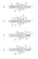
- 4 (a) to 4 (d) are schematic views showing the state of the capillary 10 at any time shown on the horizontal axis of FIG.
- the signal level of the first drive signal SgA output from the control unit 24 to the actuator 40 is a voltage (or a physical quantity correlated with the voltage).
- the actuator 40 bends by a deformation amount corresponding to the applied voltage.
- the correspondence referred to here is, for example, a one-to-one correspondence, in other words, a relation in which the amount of deformation is uniquely defined with respect to the voltage (excluding the state where the deformation is saturated). Therefore, in the actuator 40 to which the first drive signal SgA is input, the waveform of the first drive signal SgA (change with respect to the passage of voltage) so that the volume of the pressure chamber 21 becomes the volume corresponding to the voltage of the first drive signal SgA. ) Is followed by changing the volume of the pressure chamber 21.
- the relationship between the amount of change in the voltage of the first drive signal SgA and the amount of change in the volume of the pressure chamber 21 is not necessarily a proportional relationship. However, for convenience, the description will be made assuming a proportional or near-proportional relationship. Therefore, it may be considered that FIG. 3 shows not only the time-dependent change in the voltage of the first drive signal SgA but also the time-dependent change in the volume of the pressure chamber 21.
- a reference potential is applied to one of the internal electrode 42 and the surface electrode 44, and the first drive signal SgA is input to the other.
- the voltage in FIG. 3 indicates the potential difference between the reference potential and the first drive signal SgA.
- the first drive signal SgA is an unbalanced signal.
- the first drive signal SgA may be a balanced signal in which the potentials of both the internal electrode 42 and the surface electrode 44 are changed and the potential difference is the voltage shown in FIG.
- the case where the first drive signal SgA is an unbalanced signal is taken as an example. Therefore, in the following, the voltage of FIG. 3 may be described as the potential of the first drive signal SgA.
- the increase in the voltage of the first drive signal SgA may correspond to the increase in the volume of the pressure chamber 21, or may correspond to the decrease in the volume of the pressure chamber 21. ..
- the direction from the electrode to which the first drive signal SgA is applied to the electrode to which the reference potential is applied among the internal electrode 42 and the surface electrode 44 is opposite to the polarization direction of the piezoelectric ceramic layer 40a. It may be in the same orientation.
- the increase in the voltage of the first drive signal SgA corresponds to the increase in the volume of the pressure chamber 21 (that is, the suction of the liquid).
- the signal level (for example, voltage) of the second drive signal SgB output from the control unit 24 to the valve 23 is, for example, one of two types of voltages Vb0 and Vb1 corresponding to the open state and the closed state of the valve 23. Either of the two types of voltages may correspond to the open state or the closed state, but in the following description, the case where the voltage Vb0 is the closed state and the voltage Vb1 is the open state will be taken as an example.
- the second drive signal SgB may be a balanced signal or an unbalanced signal. In the following, for convenience, the voltage of FIG. 3 is used as the second drive signal. It may be described as the potential of SgB.
- One of the potentials Vb0 and Vb1 may be a reference potential.
- the voltage of the second drive signal SgB may be a voltage between the voltages Vb0 and Vb1 so as to appropriately adjust the opening degree of the valve 23, unlike the illustrated example.
- the relative relationship between the potential of the first drive signal SgA and the potential of the second drive signal SgB may be appropriately set.
- the potential Va0 at the time point t0 of the first drive signal SgA and the above-mentioned potential Vb0 of the second drive signal SgB are shown as the same value. In reality, the two can be different.
- the difference between the other potential of the first drive signal SgA and the above-mentioned potential Vb1 the actual difference between the two is not shown.
- the predetermined potential may be a reference potential.
- the control unit 24 may operate without outputting the first drive signal SgA.
- the first drive signal SgA is output at the predetermined potential even when the first drive signal SgA is not output. The same shall apply to the second drive signal SgB.
- the pipette 1 not only the operation of the pipette 1 itself, but also the operation performed by the user of the pipette 1 or the device using (or including) the pipette 1 will be described.
- a mode in which the user operates the pipette 1 will be described as an example.
- the user's operation on the pipette 1 may be appropriately read as the operation on the pipette 1 of the device.
- the movement of the pipette 1 by the user may be the movement of the pipette 1 by the device, and the operation of the pipette 1 by the user on a switch (not shown) may be the output of a command signal to the pipette 1 by the device.
- the device may perform the same operation on the pipette as the user by, for example, sequence control.
- the control unit 24 Before the time point t1, the control unit 24 outputs the initial signal SgA0 to the actuator 40 in response to the user's operation on a switch (not shown) (time points t0 to t1).
- the initial signal SgA0 is a signal having a constant potential (here, potential Va0). As a result, the volume of the pressure chamber 21 is maintained at a predetermined initial volume.
- the potential Va0 may be a reference potential or may be different from the reference potential.
- the valve 23 is closed at least after time point t1 unless otherwise specified. Further, at time points t0 to t1, the valve 23 may be closed or open. For example, when the initial signal SgA0 does not generate a driving force in the actuator 40, the valve 23 may be closed or open. Further, for example, when the initial signal SgA0 drives the actuator 40 to make the volume of the pressure chamber 21 smaller than the volume of the pressure chamber 21 before the time point t0, the valve 23 may be opened.
- the user brings the first end 11 of the capillary 10 into contact with the first liquid L1 before the time point t1 (performs a liquid contact step). Then, the user instructs the pipette 1 to suck the first liquid L1 by operating the switch (not shown) included in the pipette 1.
- the time point of this instruction corresponds to the time point t1 in FIG.
- the first suction signal SgA1 is, for example, a signal that rises from the potential Va0 of the initial signal SgA0 to a predetermined potential Va1, then falls to a predetermined potential Va2, and maintains the potential Va2.
- the first liquid L1 is sucked into the capillary 10 and held in the vicinity of the first end 11 of the capillary 10.
- the first suction signal SgA1 may be a signal that realizes such a change in the volume of the pressure chamber 21. That is, the first suction signal SgA1 may be a signal that rises from the potential Va0 to a predetermined potential and maintains the predetermined potential. In this case, the potential difference between the potential Va0 and the predetermined potential is set according to the suction amount of the first liquid L1.
- the accuracy of measuring the liquid can be improved. Specifically, it is as follows.
- a phenomenon may occur in which the suction of the liquid is continued even if the increase in the volume is stopped.
- Such a phenomenon is caused by, for example, an inertial force acting on a liquid. And it may be difficult to ignore such a phenomenon. For example, when a small amount of liquid is sucked, the variation in the suction amount caused by the above phenomenon tends to be relatively large, and it becomes difficult to suck the liquid with the intended accuracy.
- the volume of the pressure chamber 21 (increasing the pressure in the capillary 10) due to the decrease from the potential Va1 to the potential Va2, a braking force against the inertial force is applied to the liquid, and it is probable that the above phenomenon occurs. Can be reduced.
- the first suction signal SgA1 having such a waveform for example, the potential difference between the potentials Va0 and Va1, the potential difference between the potentials Va1 and Va2, and the time (pulse) from the potential Va0 to the potential Va2 via the potential Va1.
- the width) and the like can be adjusted to realize an arbitrary suction amount.
- the pulse width is relatively short, and the waveform from the potential Va0 to the potential Va2 via the potential Va1 is drawn in an impulse shape.
- the user pulls up the capillary 10 from the rest of the first liquid L1 (performs a liquid removal step).
- the user brings the first end 11 of the capillary 10 into contact with the second liquid L2 (performs a liquid contact step).
- the user instructs the pipette 1 to suck the second liquid L2 by operating the switch (not shown) included in the pipette 1.
- the time point of this instruction corresponds to the time point t2 in FIG.
- the second suction signal SgA2 is, for example, a signal that rises from the potential Va2 at the end of the first suction signal SgA1 to a predetermined potential Va3, then falls to a predetermined potential Va4, and maintains the potential Va4.
- the second liquid L2 is sucked into the capillary 10 and held near the first end 11 of the capillary 10.
- the action of the second suction signal SgA2 having a waveform in which the potential rises and then falls is the same as that of the first suction signal SgA1.
- the suction amount of the second liquid L2 is, for example, the potential difference between the potentials Va2 and Va3, the potential difference between the potentials Va3 and Va4, and the time (pulse width) from the potential Va2 to the potential Va4 via the potential Va3. Specified by adjusting.
- the pulse width is relatively short, and the waveform from the potential Va2 to the potential Va4 via the potential Va3 is drawn in an impulse shape.
- the second suction signal SgA2 may be a signal that rises from the potential Va2 to a predetermined potential and maintains the predetermined potential, unlike the illustrated example.
- the control unit 24 When a part of the second liquid L2 is sucked into the capillary 10, the user pulls up the capillary 10 from the rest of the second liquid L2 (performs a liquid removal step). Then, the user instructs the pipette 1 to perform the subsequent processing by operating the switch (not shown) possessed by the pipette 1.
- the time point of this instruction corresponds to the time point t3 in FIG.
- the control unit 24 outputs various signals in a preset order and timing, for example, from the time point t3 to the time point t12. However, the control unit 24 may start outputting at least one of the various signals when the operation on the pipette 1 is performed.
- time points t3 to t5 Restoration of pressure chamber, etc.
- the control unit 24 reduces the volume of the pressure chamber 21 to an appropriate volume (the initial volume at the time point t0 in the illustrated example) while holding the liquid near the first end 11.
- an appropriate volume the initial volume at the time point t0 in the illustrated example
- the amount that can be increased can be increased. Specifically, it is as follows.
- the control unit 24 starts the control to open the valve 23 at the time point t3. That is, the control unit 24 starts outputting the signal of the potential Vb1, which is a part of the second drive signal SgB, to the valve 23.
- Vb1 which is a part of the second drive signal SgB
- the restoration signal SgA3 is, for example, a signal that drops from the potential Va4 of the second suction signal SgA2 to a predetermined potential (for example, the potential Va0 at the time point t0) and maintains the predetermined potential Va0.
- the volume of the pressure chamber 21 is reduced by the restoration signal SgA3.
- the valve 23 is opened as described above, the pressure of the portion of the capillary 10 on the second end 12 side of the liquids (L1 and L2) is not increased. As a result, the position of the liquid does not change.
- the time length from the time point t3 to the time point t4 may be appropriately set, and may be, for example, a sufficient time to open the valve 23.
- the potential when the restoration signal SgA3 drops from the potential Va4 may be higher or lower than the initial potential Va0 (and / or the reference potential), unlike the illustrated example.
- the control unit 24 determines that a predetermined time has elapsed from the time point t4 (time point t5), the control unit 24 starts the control to close the valve 23. That is, the control unit 24 starts outputting the signal of the potential Vb0, which is a part of the second drive signal SgB, to the valve 23.
- the time length from the time point t4 to the time point t5 may be appropriately set, and is set to be sufficient time for the actuator 40 to have a displacement corresponding to the potential after the drop of the restoration signal SgA3 (here, Va0). It's okay.
- the initial position P0 and the completion position P2 may be defined as, for example, positions where a certain part of the liquid L3 should reach.
- the fixed portion may be any portion such as the lower surface, the upper surface, and the center of the liquid L3. The same applies to other positions (midway position P1, etc.) described later.
- the completion position P2 may be an arbitrary position on the second end 12 side of the initial position P0. In another aspect, the completion position P2 may be any position where all of the liquid L3 is away from the first end 11. In the illustrated example, the completion position P2 is a position where all of the liquid L3 is located in the second hole 10b. In other words, the completion position P2 is a position where the entire liquid L3 exceeds the boundary 14 between the first hole 10a and the second hole 10b (in another viewpoint, the step 10c) toward the second end 12 side. More specifically, the completion position P2 is a position where the entire liquid L3 is located in a portion of the second member 16 that is exposed to the outside (a portion that is not covered by the first member 15 in the illustrated example). ing.
- the time length from the time point t5 to the time point t6 may be appropriately set, and may be, for example, a sufficient time for the valve 23 to close.
- the waveform of the mobile signal SgA4 will be described later.
- time point t8 to t9 mixing, etc.
- the control unit 24 determines that a predetermined time has elapsed after the completion of pulling up the liquid L3 (time point t8)
- the control unit 24 outputs a mixed signal SgA5 that drives the drive unit 50 so that the volume of the pressure chamber 21 repeatedly increases and decreases.
- the liquid L3 alternately repeats the movement toward the second end 12 side and the movement toward the first end 11 side in the second hole 10b.
- the liquid L3 reciprocates between the position shown in FIG. 4 (c) and the position shown in FIG. 4 (d).
- the liquid L3 is agitated, and the mixing of the first liquid L1 and the second liquid L2 proceeds.
- the mixed signal SgA5 has a waveform in which the potential repeats rising and falling.
- the number of repetitions may be set as appropriate. Since it is repeated, for example, the potential may be raised twice or more, and the potential may be lowered twice or more.
- the waveform may be a curved line (for example, a sine wave) as in the illustrated example, or may be a square wave, a triangular wave, or a sawtooth wave unlike the illustrated example.
- the amplitude of the waveform may be constant or may change.
- the plurality of maximum values Va5 of the potential may be the same as each other or may be different from each other.
- the plurality of minimum values Va6 of the potential may be the same as each other or may be different from each other.
- the plurality of maximum values Va5 are the same as each other, and the plurality of minimum values Va6 are the same as each other.
- the initial fluctuation of the potential in the mixed signal SgA5 may be an increase in the potential or a decrease in the potential.
- the final fluctuation of the potential in the mixed signal SgA5 may be an increase in the potential or a decrease in the potential.
- the minimum value of the mixed signal SgA5 is slightly higher than the potential at the start of output of the mixed signal SgA5 (time point t8).
- the amount of increase in the first potential is higher than the amount of increase in the potential after the second time.
- the reason is as follows, for example. Before the start of the initial increase in potential, the gas on the first end 11 side of the liquid L3 is considered to be equivalent to the pressure outside the pipette 1. On the other hand, before the start of the increase in the potential after the second time, the gas on the first end 11 side of the liquid L3 is slightly compressed by the decrease in the potential immediately before (the flow of the liquid L3 to the first end 11 side). The pressure of the gas is slightly higher than the pressure outside the pipette 1. This is due to the resistance of the gas as it is expelled from the first end 11. Then, in consideration of this pressure difference, the amount of increase in the initial potential is slightly increased.
- the potential drops from the maximum value Va5 to the minimum value Va6, and then rises slightly to reach the potential Va7.
- This slight increase in potential contributes to exerting a braking force on the liquid L3 against the inertial force acting on the liquid L3, for example, as mentioned in the description of the first suction signal SgA1.
- the position of the liquid L3 at the completion of mixing can be easily brought closer to the position of the liquid L3 at the start of mixing (time point t8).
- time points t9 to t12 Liquid retention, etc.
- the control unit 24 determines that a predetermined time has elapsed after the completion of mixing the liquid L3 (time point t10), the control unit 24 holds the position of the liquid L3. This operation may merely maintain the potential Va7. However, in the illustrated example, processing is performed to reduce the load on the actuator 40. Specifically, it is as follows.
- the control unit 24 from the time point t10 to the time point t12 is the same as that of the time point t3 to t5 except for the specific potential value and the rate of change. That is, the input of the first drive signal SgA to the actuator 40 is stopped while the valve 23 is open (time points t10 to t11). As a result, the volume of the pressure chamber 21 is reduced by the restoring force. Since the valve 23 is open, the pressure on the second end 12 side of the liquid L3 in the capillary 10 does not change, and the position of the liquid L3 is maintained. After that, the valve 23 is closed (time point t12), and the movement of the liquid L3 is restricted.
- the liquid L3 is irradiated with light from the side of the capillary 10 while being held in the capillary 10 (for example, in the second member 16), and its properties are examined. For example, fluorescence measurement, scattering measurement, absorption measurement and / or spectroscopic measurement are performed. Prior to the measurement, the liquid may be moved from the position immediately after mixing to a position suitable for the measurement.
- FIG. 5 is a diagram showing a part of FIG. 3 (generally in the range of time points t6 to t7) with different ratios of the vertical axis and the horizontal axis.
- the waveform of the movement signal SgA4 for pulling up the liquid is shown.
- 6 (a) to 6 (d) are schematic views showing the state of the capillary 10 at any time shown on the horizontal axis of FIG.
- the movement signal SgA4 includes, for example, the initial movement signal SgA41 output at the time point t6 and the vibration movement signal SgA42 output thereafter.
- the initial movement signal SgA41 contributes to, for example, moving the liquid from the initial position P0 shown in FIG. 4 (b) to the intermediate position P1 shown in FIG. 6 (a).
- the vibration movement signal SgA42 contributes to moving the liquid from, for example, the intermediate position P1 to the completion position P2 shown in FIG. 4 (c).
- the movement signal SgA4 does not have the initial movement signal SgA41, and may be configured to move the liquid from the initial position P0 to the completion position P2 by the vibration movement signal SgA42.
- the midway position P1 may be any position on the second end 12 side of the initial position P0 and on the first end 11 side of the completed position P2.
- the intermediate position P1 is a position where the entire liquid L3 is contained in the first hole 10a.
- the entire liquid L3 does not reach the boundary 14 between the first hole 10a and the second hole 10b (step 10c from another viewpoint), or the upper surface of the liquid L3 touches the step 10c. It is said to be in the position of the degree.
- the initial movement signal SgA41 has, for example, a waveform in which the potential rises in a relatively short time (pulse width) and then falls. That is, the initial movement signal SgA41 has a pulse-like (further, impulse-like) waveform.
- the pulse width the period T1 from the start of the increase in the potential to the completion of the decrease in the potential
- the actuator 40 has a length of time that can be displaced according to the change in the potential. Have. Therefore, the actuator 40 increases and decreases the volume of the pressure chamber 21 as the potential of the initial movement signal SgA41 rises and falls.
- the initial movement signal SgA41 including the rise and fall of the electric potential has the same effect as the first suction signal SgA1. That is, as the volume of the pressure chamber 21 increases, the pressure on the second end 12 side of the liquid L3 in the capillary 10 is reduced, and the liquid L3 flows from the initial position P0 to the intermediate position P1. Due to the subsequent decrease in the volume of the pressure chamber 21, the pressure on the second end 12 side of the liquid L3 in the capillary 10 is increased, and the braking force against the inertial force on the second end 12 side acting on the liquid L3 is the liquid L3. Acts on. The action of the braking force improves the accuracy of the stop position of the liquid L3.
- the potential Va2 after the descent is higher than the potential Va0 before the rise.
- the initial movement signal SgA41 the potential after the fall is equivalent to the potential Va0 before the rise.
- the initial movement signal SgA41 moves the liquid L3 by a voltage Va11 higher than the voltage Va1 of the first suction signal SgA1.
- the initial movement signal SgA41 is set so that the potential drops to Va0, unlike the first suction signal SgA1.
- the amount of movement of the liquid L3 can be defined by adjusting, for example, the potential difference between the potentials Va0 and Va11, the length of the period T1, and the like as parameters.
- the period T1 may be set as appropriate and may be relatively short as described above. The length of the period T1 and the like will be described later in comparison with the time length of the vibration transfer signal SgA42.
- the initial movement signal SgA41 has a waveform in which the potential does not drop to the potential Va0 before the potential rises (the same waveform as the first suction signal SgA1). May be good.
- the moving amount of the liquid L3 may be defined by adjusting the potential difference at the time of rising, the potential difference at the time of falling, the period T1 and the like, similarly to the suction amount of the first liquid L1 by the first suction signal SgA1.
- the vibration transfer signal SgA42 has a waveform in which the potential repeats rising and falling, similarly to the mixed signal SgA5.
- the volume of the pressure chamber 21 repeatedly increases and decreases.
- the liquid L3 gradually moves from the intermediate position P1 to the completed position P2 while repeating the movement from the intermediate position P1 side to the completed position P2 side and the movement to the opposite side.
- FIG. 6 (a) to 6 (d) schematically show a part of the vibrating movement of the liquid L3. That is, the liquid L3 rises from the midway position P1 shown in FIG. 6A to the position P21 shown in FIG. 6B. This position P21 is a position closer to the intermediate position P1 than the completed position P2. Next, the liquid L3 moves from the position P21 to the position P22 shown in FIG. 6 (c). The position P22 is a position closer to the completion position P2 than the intermediate position P1. Next, the liquid L3 moves from the position P22 to the position P23 shown in FIG. 6 (d). The position P23 is a position on the completion position P2 side of the previous position P21 at the time of ascending.
- the liquid L3 is located on the intermediate position P1 side of the position P23 and on the completed position P2 side of the position P21 (the position at the time of the previous descent) in FIG. 6 (b). Move to. While repeating such vibration an appropriate number of times, the liquid L3 moves from the intermediate position P1 to the completed position P2.
- the liquid L3 is gradually completed by repeating the movement from the intermediate position P1 side to the completion position P2 side and the stop of the movement by increasing or decreasing the volume of the pressure chamber 21. You may move to position P2.
- the number of repetitions of the increase and decrease of the electric potential in the vibration movement signal SgA42 may be appropriately set. Since it is repeated, for example, the volume of the pressure chamber 21 may be increased twice or more, and the volume of the pressure chamber 21 may be decreased twice or more.
- the waveform of the vibration transfer signal SgA42 may be a curved line (for example, a sine wave) as shown in the illustrated example, or may be a square wave, a triangular wave, or a sawtooth wave unlike the illustrated example.
- the amplitude of the waveform may be constant or may change.
- the plurality of maximum values Va12 of the potential may be the same as each other or may be different from each other.
- the plurality of minimum values Va13 of the potential may be the same as each other or may be different from each other.
- the plurality of maximum values Va12 are the same as each other, and the plurality of minimum values Va13 are the same as each other.
- the liquid L3 vibrates in the same range and heads toward the completion position P2. Does not seem to move. Further, in the explanation of the mixed signal SgA5, it was explained as such. However, in reality, the liquid L3 moves toward the completion position P2 by the vibration movement signal SgA42.
- the inner surface of the first hole 10a has a tapered surface whose diameter becomes smaller toward the first end 11 side.
- the flow path resistance when the liquid L3 flows toward the first end 11 is larger than the flow path resistance when the liquid L3 flows toward the second end 12.
- the amount of movement of the liquid L3 to the first end 11 side is smaller than the amount of movement of the liquid L3 to the second end 12 side.
- the liquid L3 gradually moves to the completion position P2 while repeating vibration.
- the second hole 10b has a smaller diameter and higher hydrophilicity than the first hole 10a.
- the capillary force that causes the liquid L3 to flow from the first hole 10a to the second hole 10b acts on the liquid L3.
- the liquid L3 gradually moves to the completion position P2 while repeating vibration.
- the liquid L3 In the case where the liquid L3 easily flows in the direction from the first hole 10a to the second hole 10b as described above, if the minimum value Va13 is the same size as each other, each time the potential becomes the minimum value Va13. , The liquid L3 is closer to the completion position P2 than at the previous minimum value Va13. In other words, when each of the second and subsequent volume reductions of the repeated volume reduction of the pressure chamber 21 is completed, the liquid L3 is the position of the liquid L3 when the previous volume reduction is completed. It is located on the side of the completion position P2. Although the minimum value Va13 has been described, the same can be said for the maximum value Va12. That is, when each of the second and subsequent volume increases of the repeated volume increase of the pressure chamber 21 is completed, the liquid L3 is higher than the position of the liquid L3 when the previous volume increase is completed. It is located on the completion position P2 side.
- the position of the liquid L3 when the volume reduction of the pressure chamber 21 is completed is the position of the liquid L3 when the previous volume reduction is completed. It may include a peculiar movement located at the same position as or closer to the first end 11 side than the position. Such peculiar movement contributes, for example, to the promotion of mixing of liquid L3. Further, when the movement of the liquid L3 to the completion position P2 side progresses to some extent, the ease of flow from the first hole 10a to the second hole 10b becomes equivalent to the ease of flow in the opposite direction, which is caused by this.
- the position of the liquid L3 when the potential drop is completed may be the same as the position of the liquid L3 when the previous potential drop is completed.
- the initial fluctuation of the potential in the vibration transfer signal SgA42 may be, for example, an increase in the potential (illustration) or a decrease in the potential.
- the time for moving the liquid L3 to the completion position P2 can be shortened as compared with the latter case.
- the final fluctuation of the potential in the vibration transfer signal SgA42 may be an increase in the potential or a decrease in the potential (illustrated example).
- a braking force can be applied to the liquid L3 by lowering the potential, and the probability that the liquid L3 exceeds the completion position P2 due to an inertial force or the like can be reduced.
- the amplitude of the potential of the vibration transfer signal SgA42 may be set appropriately.
- the amplitude of the vibration transfer signal SgA42 is smaller than the amplitude of the mixed signal SgA5. Therefore, for example, the speed at which the liquid moves according to the vibration movement signal SgA42 is more likely to be suppressed than the speed at which the liquid moves due to the mixing signal SgA5.
- the amount of increase in the vibration transfer signal SgA42 from the minimum value Va13 to the maximum value Va12 is made smaller than the amount of increase in the potential of the initial transfer signal SgA41. There is.
- the maximum value Va12 and the minimum value Va13 of the vibration movement signal SgA42 may also be set as appropriate.
- the maximum value Va12 is made smaller than the maximum potential Va11 of the initial movement signal SgA41.
- the maximum value Va12 is about the same as the maximum value Va5 of the mixed signal SgA5 (for example, the difference between the two is smaller than the difference between the maximum value Va12 and the potential Va11), and the former is larger than the latter. Is also slightly larger.
- the minimum value Va13 is larger than the minimum value Va6 of the mixed signal SgA5 in the illustrated example.
- the minimum value Va13 of the vibration movement signal SgA42 is the potential when the first increase in the potential of the vibration movement signal SgA42 is started (in the illustrated example, the potential Va0 at the time point t21.
- the vibration movement signal It is made larger than the potential at the start of output of SgA42 and / or the reference potential).
- the volume of the pressure chamber 21 when each of the repeated reductions in the volume of the pressure chamber 21 is completed is the pressure chamber 21 when the first increase in the volume of the repeated pressure chamber 21 is started. Is larger than the volume of.
- the amount of increase in volume in the second and subsequent increases is the amount of increase in the first volume. Smaller than As a result, for example, as will be described later, the probability that the speed of the liquid L3 will increase in the second and subsequent increases is reduced.
- the potential drops to the potential Va14, which is lower than the minimum value Va13, at the end of the repeated rise and fall of the potential.
- the inertial force acting on the liquid L3 and / or the braking force against the capillary force can be applied to the liquid L3.
- the accuracy of the stop position of the liquid L3 is improved.
- the length of the period of increase and decrease of the potential of the vibration transfer signal SgA42 may be appropriately set.
- the period T2 may be shorter, equivalent, or longer than the period (signature omitted) of the mixed signal SgA5.
- the equivalent here may be, for example, a state in which the difference between the two is 20% or less or 10% or less, whichever is shorter.
- the period T2 may be, for example, 0.1 seconds or more or 0.5 seconds or more, 10 seconds or less, 5 seconds or less, or 2 seconds or less, and the above lower limit and upper limit are appropriate. May be combined with.
- the waveform of the initial movement signal SgA41 may be in the form of a pulse or an impulse as described above. That is, the waveform of the initial movement signal SgA41 may have a sudden change in potential. Whether or not the potential changes abruptly may be specified, for example, by comparison with the vibration transfer signal SgA42.
- the period T1 is shorter than the period T2 in the vibration movement signal SgA42. More specifically, the period T1 may be 1/2 or less, 1/5 or less, 1/10 or less, or 1/20 or less of the period T2. Further, the period T1 may be, for example, 0.1 seconds or less.
- the amount of increase in the potential of the initial movement signal SgA41 (Va11-Va0) is, for example, the amount of increase in the potential of the vibration movement signal SgA42 once (the first Va12-Va0 and / or the second and subsequent Va12-Va13). Larger than. However, when the distance between the initial position P0 and the intermediate position P1 is relatively short, the former may be equal to or less than the latter, unlike the illustrated example.
- the value obtained by dividing the amount of increase in the potential of the initial movement signal SgA41 (Va11-Va0) by the period T1 ((Va11-Va0) / T1) is, for example, the amount of increase in the potential of the vibration movement signal SgA42 for a period of one time. It is larger than the value divided by T2 ((Va12-Va13) / T2).
- the latter may be defined as Va12-Va13 divided by the period from the time point t21 to the first minimum value Va13.
- the value obtained by dividing the amount of increase in the volume of the pressure chamber 21 by the initial movement signal SgA41 by the period T1 from the start of increase to the completion of decrease of the pressure chamber 21 by the initial movement signal SgA41 is the value obtained by dividing the volume of the pressure chamber 21 by the vibration movement signal SgA42. It is larger than the value obtained by dividing the amount of increase due to one increase in the volume of 21 by the period from the start of the one increase to the completion of the next decrease (for example, period T2).
- the pipette 1 has a capillary 10, a pressure chamber 21, a drive unit 50, and a control unit 24.
- the capillary 10 is open at both ends 11 and 12 at both ends in the length direction.
- the pressure chamber 21 leads to the inside of the capillary 10 via the second end 12.
- the drive unit 50 changes the volume of the pressure chamber 21.
- the control unit 24 controls the drive unit 50.
- the control unit 24 moves the liquid L3 from the first position (intermediate position P1) in the capillary 10 to the second position (completion position P2) located on the second end 12 side of the intermediate position P1.
- the first movement signal (vibration movement signal SgA42) for driving the drive unit 50 is output.
- the vibration movement signal SgA42 has a waveform that drives the drive unit 50 so that the volume of the pressure chamber 21 alternately repeats increasing and decreasing.
- the speed of the liquid L3 can be reduced.
- the speed of the liquid L3 can be reduced by reducing the volume of the pressure chamber 21 and applying the braking force to the liquid L3. For example, it is possible to make the speed of the liquid L3 lower than the speed at which the liquid L3 flows only by the capillary force.
- the mode in which the velocity of the liquid L3 is increased by the capillary force is taken as an example, but the effect of facilitating the decrease in the velocity can be achieved even in the embodiment in which such a capillary force is not generated.
- the velocity of the liquid L3 with respect to the rate of change of the increase in the volume of the pressure chamber 21 is substantially compared with the case where the volume of the pressure chamber 21 is continuously increased. Can be lowered.
- the effect of lowering the speed of the liquid L3 has been focused on, but other effects may be expected in addition to or in place of the effect.
- the vibration of the liquid L3 causes the mixing of the first liquid L1 and the second liquid L2. proceed. Therefore, for example, the liquid can be moved to a position suitable for measurement while mixing the liquid.
- the vibration transfer signal SgA42 is such that the liquid L3 is located closer to the completion position P2 than the intermediate position P1 when the final reduction of the repeated volume reductions of the pressure chamber 21 is completed.
- the vibration transfer signal SgA42 can be clearly distinguished from the mixed signal SgA5 depending on whether or not it has such a waveform.
- the vibration transfer signal SgA42 indicates that the liquid L3 has completed the previous reduction when each of the second and subsequent reductions of the repeated volume reduction of the pressure chamber 21 is completed. It has a waveform that drives the drive unit 50 so as to be located on the completion position P2 side of the position of the liquid L3.
- the liquid L3 moves to the completion position P2 every time the volume of the pressure chamber 21 decreases, and the specific movement of the liquid L3 is not performed. Therefore, the probability that the velocity of the liquid L3 will increase due to the specific movement is reduced. For example, by increasing the amount of decrease (and / or increase) of the volume at one time, the probability that the velocity of the liquid L3 is temporarily increased is reduced.
- the inner surface of the capillary 10 is a tapered surface (first hole 10a) in which the inner diameter of the capillary 10 becomes smaller toward the intermediate position P1 in at least a part of the range from the intermediate position P1 to the completed position P2.
- the inner surface of is a tapered surface (first hole 10a) in which the inner diameter of the capillary 10 becomes smaller toward the intermediate position P1 in at least a part of the range from the intermediate position P1 to the completed position P2.
- the amount of movement of the liquid L3 to the intermediate position P1 side is smaller than the amount of movement of the liquid L3 to the completion position P2 side. Therefore, for example, the liquid L3 can be moved to the completion position P2 side even if the plurality of minimum values Va13 are the same as each other. Therefore, for example, it is easy to set the waveform of the vibration movement signal SgA42. From another point of view, the velocity of the liquid L3 can be defined by the setting of the tapered surface.
- the waveform of the vibration movement signal SgA42 is composed of a curved line.
- the waveform is a sine wave.
- the volume of the pressure chamber 21 is maximized as compared with a mode in which the waveform of the vibration transfer signal SgA42 is a rectangular wave having the same amplitude and period as the sine wave (this mode is also included in the present disclosure).
- This mode is also included in the present disclosure.
- the time to maintain the value is shortened. As a result, it becomes easy to reduce the speed of the liquid L3.
- the vibration transfer signal SgA42 is the amount of increase in volume in the second and subsequent increases in the repeated increase in volume of the pressure chamber 21 (from another viewpoint, the potential from the minimum value Va13 to the maximum value Va12).
- the driving unit 50 is driven so that the amount of increase in volume) is smaller than the amount of increase in initial volume (the amount of increase in potential from potential Va0 at time point t21 to the first maximum value Va12).
- the probability that the speed of pulling up the liquid will increase in the second and subsequent volume increases is reduced.
- it is as follows.
- the pressure of the gas on the first end 11 side of the liquid L3 is equal to the pressure outside the pipette 1.
- the gas on the first end 11 side of the liquid L3 is compressed by the volume decrease immediately before that. This is due to the resistance of the gas as it is expelled from the first end 11. Therefore, the speed at which the liquid is pulled up tends to increase in the second and subsequent volume increases. Therefore, the increase in speed can be suppressed by reducing the amount of increase in volume from the second time onward.
- control unit 24 causes the liquid L3 to move from the third position (initial position P0) on the first end 11 side of the intermediate position P1 to the intermediate position P1 before the vibration movement signal SgA42.
- a second movement signal (initial movement signal SgA41) for driving the drive unit 50 is output.
- the initial movement signal SgA41 has a waveform that drives the drive unit 50 so as to increase and then decrease the volume of the pressure chamber 21.
- the value obtained by dividing the amount of increase in the volume of the pressure chamber 21 by the initial movement signal SgA41 by the period T1 from the start of the increase to the completion of the decrease of the pressure chamber 21 by the initial movement signal SgA41 (from another viewpoint (Va11-Va0) / T1) is ,
- the value obtained by dividing the amount of increase due to one increase in the volume of the pressure chamber 21 by the vibration transfer signal SgA42 by the period T2 from the start of the one increase to the completion of the next decrease (from another viewpoint (from another viewpoint). It is larger than Va12-Va13) / T2).
- the liquid L3 can be quickly moved by the initial movement signal SgA41 from the initial position P0 to the intermediate position P1 (to the position where the movement of the liquid L3 by the vibration movement signal SgA42 starts).
- the initial movement signal SgA41 has a waveform that allows the braking force to act on the liquid L3 by reducing the volume of the pressure chamber 21, the liquid L3 moves at high speed due to the rapid movement by the initial movement signal SgA41. The probability of exceeding the midway position P1 is reduced.
- the inner surface of the capillary 10 has a step 10c between the intermediate position P1 and the completed position P2.
- the liquid L3 moves at a low speed by the vibration movement signal SgA42 and exceeds the step 10c.
- the probability that the liquid L3 will separate is reduced. Specifically, it is as follows.
- 7 (a) to 7 (c) are cross-sectional views for explaining how the liquid L3 is separated, and corresponds to a part of FIG.
- FIG. 7A shows a state in which the liquid L3 is flowing from the first hole 10a to the second hole 10b beyond the step 10c.
- a vortex flow 70 is likely to occur before the step 10c.
- the vortex flow 70 tends to hinder the inflow of the liquid L3 from the first hole 10a to the second hole 10b.
- FIG. 7B the other part of the liquid L3 moves upward from the step 10c with a part of the liquid L3 remaining in front of the step 10c.
- the liquid L3 exceeds the step 10c at a relatively low speed by the vibration movement signal SgA42. Therefore, the magnitude and / or strength of the vortex 70 is reduced. As a result, the liquid L3 is less likely to remain on the step 10c. As a result, the probability that the liquid L3 will separate is reduced.
- the step 10c In order to prevent the liquid L3 from separating at the step 10c, it is conceivable to eliminate the step 10c.
- the step 10c also has the effect of mixing the liquid L3 with the vortex 70. Therefore, the magnitude and / or strength of the vortex 70 is adjusted by reducing the velocity of the liquid L3 instead of eliminating the step 10c, and the effect of mixing the liquid L3 and the probability of separation of the liquid L3 are reduced. It is possible to achieve both the effects of.
- FIG. 8 is a diagram showing the vibration movement signal SgA45 according to the first modification, and corresponds to FIG.
- the minimum value of the potential of the oscillating transfer signal SgA45 is the potential when the potential of the oscillating transfer signal SgA45 starts to rise for the first time (in the illustrated example, the potential Va0 at time point t21, in another viewpoint, the potential is Va0.
- the potential at the start of output of the vibration transfer signal SgA45 and / or the reference potential) may be the same.
- the volume of the pressure chamber 21 when each of the repeated reductions in the volume of the pressure chamber 21 is completed is the pressure chamber 21 when the first increase in the volume of the repeated pressure chamber 21 is started. May be equivalent to the volume of.
- the plurality of maximum values Va12 are the same as each other, from another viewpoint, among the repeated increases in the volume of the pressure chamber 21, the amount of increase in volume in the second and subsequent increases is the amount of increase in the first volume. May be equivalent to.
- the liquid L3 can be moved at a lower speed than in the case where the liquid L3 is moved from the intermediate position P1 to the completed position P2 by a pulse wave such as the initial movement signal SgA41.
- the control unit 24 does not automatically output the mixing signal SgA5 after outputting the vibration movement signal SgA45, but may wait for the user's operation on the operation unit (for example, the switch group) of the pipette body 20. Then, the control unit 24 may output the replenishment signal SgA6 shown on the right side (the side on which the time t has elapsed) from the line Ln1 in FIG. 8 in accordance with a predetermined operation. Further, the control unit 24 may output the mixed signal SgA5 without outputting the replenishment signal SgA6 or after the output of the replenishment signal SgA6 is completed, in accordance with a predetermined operation.
- the replenishment signal SgA6 is a signal for correcting the position of the liquid L3 when the liquid L3 is not positioned at an arbitrary position (here, the completion position P2) by the vibration movement signal SgA45.
- the waveform may be set as appropriate.
- the replenishment signal SgA6 may be combined with the embodiments and modifications described below.
- FIG. 9 is a diagram showing a vibration movement signal SgA47 according to the second modification, and corresponds to a part of FIG.
- the maximum value Va12 and the minimum value Va13 of the vibration movement signal SgA47 may gradually increase.
- the volume of the pressure chamber 21 when each of the repeated volume increases of the pressure chamber 21 is completed may be gradually increased. Further, the volume of the pressure chamber 21 when each of the repeated reductions in the volume of the pressure chamber 21 is completed may be gradually increased.
- the reason why the liquid L3 moves from the first end 11 side to the second end 12 side is illustrated even if the plurality of maximum values Va12 are the same as each other and the plurality of minimum values Va13 are the same as each other. However, even if such a reason does not exist, the vibration movement signal SgA47 can move the liquid L3 from the first end 11 side to the second end 12 side at a low speed. That is, in the present disclosure, the capillary 10 may not have a tapered surface, and may not have a portion having a stronger capillary force than the second end 12 side.
- the intermediate position P1 is an example of the first position.
- the completion position P2 is an example of the second position.
- the vibration movement signal SgA42 is an example of the first movement signal.
- the initial position P0 is an example of the third position.
- the initial movement signal SgA41 is an example of the second movement signal.
- the pipette is not limited to the one that can mix the two liquids.
- the pipette may suck one liquid and pull the one liquid to an appropriate position.
- the first drive signal SgA does not have to include the second suction signal SgA2.
- the pipette may be capable of sucking three or more liquids.
- the first drive signal SgA does not have to include the initial movement signal SgA41. Further, the first drive signal SgA may not include the mixed signal SgA5.
- the first drive signal SgA, which does not include the mixing signal SgA5 may be applied, for example, to pipettes where liquid agitation is not expected. Further, the first drive signal SgA that does not include the mixing signal SgA5 may be applied to a pipette that is expected to agitate the liquid. This is because the vibration transfer signal SgA42 can exert a mixing action.
- the pipette may not have a valve 23. Further, when the pipette has a valve 23, the opening / closing timing of the pipette may be different from that of the embodiment.
Landscapes
- Health & Medical Sciences (AREA)
- Chemical & Material Sciences (AREA)
- Clinical Laboratory Science (AREA)
- Chemical Kinetics & Catalysis (AREA)
- General Health & Medical Sciences (AREA)
- Biochemistry (AREA)
- Physics & Mathematics (AREA)
- General Physics & Mathematics (AREA)
- Immunology (AREA)
- Pathology (AREA)
- Analytical Chemistry (AREA)
- Life Sciences & Earth Sciences (AREA)
- Automatic Analysis And Handling Materials Therefor (AREA)
- Devices For Use In Laboratory Experiments (AREA)
Priority Applications (4)
| Application Number | Priority Date | Filing Date | Title |
|---|---|---|---|
| US17/638,854 US12427512B2 (en) | 2019-09-03 | 2020-09-01 | Pipette |
| EP20861733.2A EP3998119B1 (en) | 2019-09-03 | 2020-09-01 | Pipette |
| CN202080057434.9A CN114222631A (zh) | 2019-09-03 | 2020-09-01 | 移液管 |
| JP2021543776A JP7317126B2 (ja) | 2019-09-03 | 2020-09-01 | ピペット |
Applications Claiming Priority (2)
| Application Number | Priority Date | Filing Date | Title |
|---|---|---|---|
| JP2019160014 | 2019-09-03 | ||
| JP2019-160014 | 2019-09-03 |
Publications (1)
| Publication Number | Publication Date |
|---|---|
| WO2021045043A1 true WO2021045043A1 (ja) | 2021-03-11 |
Family
ID=74852960
Family Applications (1)
| Application Number | Title | Priority Date | Filing Date |
|---|---|---|---|
| PCT/JP2020/033054 Ceased WO2021045043A1 (ja) | 2019-09-03 | 2020-09-01 | ピペット |
Country Status (5)
| Country | Link |
|---|---|
| US (1) | US12427512B2 (https=) |
| EP (1) | EP3998119B1 (https=) |
| JP (1) | JP7317126B2 (https=) |
| CN (1) | CN114222631A (https=) |
| WO (1) | WO2021045043A1 (https=) |
Families Citing this family (1)
| Publication number | Priority date | Publication date | Assignee | Title |
|---|---|---|---|---|
| EP4700391A1 (de) * | 2024-08-22 | 2026-02-25 | Hombrechtikon Systems Engineering AG | Verfahren zum mischen von fluiden, und pipettiervorrichtung |
Citations (9)
| Publication number | Priority date | Publication date | Assignee | Title |
|---|---|---|---|---|
| JPS60189332U (ja) * | 1984-05-28 | 1985-12-14 | 株式会社三鈴エリー | 自動吸入ピペツト |
| JPH05184949A (ja) * | 1992-01-13 | 1993-07-27 | Fuji Photo Film Co Ltd | 微量定容ピペット |
| JPH0616852U (ja) * | 1992-07-31 | 1994-03-04 | 株式会社島津製作所 | 分光光度計用セル |
| JPH1062437A (ja) | 1996-05-02 | 1998-03-06 | Bayer Corp | 試料希釈方法 |
| JP2000304754A (ja) | 1999-02-12 | 2000-11-02 | Ortho Clinical Diagnostics Inc | 液体を混合するための方法及び装置 |
| JP2002018800A (ja) * | 2000-04-28 | 2002-01-22 | Eppendorf Ag | ガスクッション式分配マイクロシステム |
| WO2018181023A1 (ja) * | 2017-03-29 | 2018-10-04 | 京セラ株式会社 | キャピラリーおよびそれを用いたピペット |
| WO2020050235A1 (ja) * | 2018-09-03 | 2020-03-12 | 京セラ株式会社 | ピペット及び液体採取方法 |
| WO2020050234A1 (ja) * | 2018-09-03 | 2020-03-12 | 京セラ株式会社 | キャピラリー及びピペット |
Family Cites Families (15)
| Publication number | Priority date | Publication date | Assignee | Title |
|---|---|---|---|---|
| AU670449B2 (en) | 1992-06-08 | 1996-07-18 | Behring Diagnostics Inc. | Liquid dispensing system |
| US20030215957A1 (en) * | 1998-02-20 | 2003-11-20 | Tony Lemmo | Multi-channel dispensing system |
| US6551557B1 (en) * | 1998-07-07 | 2003-04-22 | Cartesian Technologies, Inc. | Tip design and random access array for microfluidic transfer |
| JP2004202893A (ja) * | 2002-12-25 | 2004-07-22 | Seiko Epson Corp | インクジェットヘッドの駆動制御方法、インクジェットプリンタの駆動制御方法およびインクジェットプリンタ |
| DE102004009012A1 (de) * | 2004-02-25 | 2005-09-15 | Roche Diagnostics Gmbh | Testelement mit einer Kapillare zum Transport einer flüssigen Probe |
| DE102004022419B4 (de) * | 2004-05-06 | 2007-01-25 | Eppendorf Ag | Pipette |
| US7560893B2 (en) * | 2007-06-12 | 2009-07-14 | Xerox Corporation | Dual mode stepper motor |
| EP2633914B2 (de) * | 2012-03-02 | 2020-04-08 | Eppendorf AG | Pipettiervorrichtung und Verfahren zu ihrer Herstellung |
| DE102014013158A1 (de) * | 2014-09-11 | 2016-03-17 | Burkhard Büstgens | Freistrahl-Einrichtung |
| CN105944584B (zh) * | 2016-05-23 | 2018-12-07 | 徐州雷鸣民爆器材有限公司 | 一种用于液-液混合乳化的静态混合器及其工作方法 |
| WO2018091075A1 (en) * | 2016-11-15 | 2018-05-24 | Tecan Schweiz Ag | Pipetting method and pipetting device |
| DE102016225209A1 (de) * | 2016-12-15 | 2018-06-21 | Hamilton Bonaduz Ag | Pipettiervorrichtung zur verbesserten impulsartigen Flüssigkeitspipettierung |
| DE102017201114A1 (de) * | 2017-01-24 | 2018-07-26 | Hamilton Bonaduz Ag | Pipettiervorrichtung zur impulsartigen Pipettierung mit einer basierend auf einer Erfassung des Arbeitsgasdrucks geregelten Pipettierkolbenbewegung |
| US10189018B2 (en) * | 2017-05-31 | 2019-01-29 | Vistalab Technologies, Inc. | Method and apparatus for dispensing precise aliquots of liquid |
| CN107344030B (zh) * | 2017-09-14 | 2020-05-22 | 西南民族大学 | 用于w/o型乳状液的破乳装置以及破乳方法 |
-
2020
- 2020-09-01 WO PCT/JP2020/033054 patent/WO2021045043A1/ja not_active Ceased
- 2020-09-01 US US17/638,854 patent/US12427512B2/en active Active
- 2020-09-01 CN CN202080057434.9A patent/CN114222631A/zh active Pending
- 2020-09-01 EP EP20861733.2A patent/EP3998119B1/en active Active
- 2020-09-01 JP JP2021543776A patent/JP7317126B2/ja active Active
Patent Citations (9)
| Publication number | Priority date | Publication date | Assignee | Title |
|---|---|---|---|---|
| JPS60189332U (ja) * | 1984-05-28 | 1985-12-14 | 株式会社三鈴エリー | 自動吸入ピペツト |
| JPH05184949A (ja) * | 1992-01-13 | 1993-07-27 | Fuji Photo Film Co Ltd | 微量定容ピペット |
| JPH0616852U (ja) * | 1992-07-31 | 1994-03-04 | 株式会社島津製作所 | 分光光度計用セル |
| JPH1062437A (ja) | 1996-05-02 | 1998-03-06 | Bayer Corp | 試料希釈方法 |
| JP2000304754A (ja) | 1999-02-12 | 2000-11-02 | Ortho Clinical Diagnostics Inc | 液体を混合するための方法及び装置 |
| JP2002018800A (ja) * | 2000-04-28 | 2002-01-22 | Eppendorf Ag | ガスクッション式分配マイクロシステム |
| WO2018181023A1 (ja) * | 2017-03-29 | 2018-10-04 | 京セラ株式会社 | キャピラリーおよびそれを用いたピペット |
| WO2020050235A1 (ja) * | 2018-09-03 | 2020-03-12 | 京セラ株式会社 | ピペット及び液体採取方法 |
| WO2020050234A1 (ja) * | 2018-09-03 | 2020-03-12 | 京セラ株式会社 | キャピラリー及びピペット |
Also Published As
| Publication number | Publication date |
|---|---|
| EP3998119A1 (en) | 2022-05-18 |
| CN114222631A (zh) | 2022-03-22 |
| JP7317126B2 (ja) | 2023-07-28 |
| US20220288579A1 (en) | 2022-09-15 |
| EP3998119A4 (en) | 2022-10-26 |
| EP3998119B1 (en) | 2023-11-08 |
| JPWO2021045043A1 (https=) | 2021-03-11 |
| US12427512B2 (en) | 2025-09-30 |
Similar Documents
| Publication | Publication Date | Title |
|---|---|---|
| JPWO2020050234A1 (ja) | キャピラリー及びピペット | |
| Laurell et al. | Design and development of a silicon microfabricated flow-through dispenser for on-line picolitre sample handling | |
| JP3463929B2 (ja) | 体積センサのない微量分注デバイス、分注デバイス配列、および微量分注デバイスの使用用途 | |
| US9387492B2 (en) | Liquid droplet dispenser | |
| JP5504508B2 (ja) | 吐出ヘッドおよび吐出装置 | |
| CN112638536B (zh) | 移液管以及液体提取方法 | |
| JP6426882B1 (ja) | キャピラリーおよびそれを用いたピペット | |
| WO2021045043A1 (ja) | ピペット | |
| JPH08312537A (ja) | 粘性物質用のポンプ | |
| JP7245135B2 (ja) | プレウォッシュ方法、液体吸引装置及びピペット | |
| CN112297630A (zh) | 液体喷射装置 | |
| JP6630028B1 (ja) | ピペット及び液体採取方法 | |
| JPH08219956A (ja) | ピペット及びその使用方法 | |
| JP7261129B2 (ja) | ピペット、液体吸引装置及び液体の吸引方法 | |
| You et al. | Acoustofluidic based wireless micropump for portable drug delivery applications | |
| JP6430782B2 (ja) | マイクロピペットの制御方法 | |
| JP2000310645A (ja) | 液体分注装置 | |
| JP6940449B2 (ja) | ピペットおよびそれを用いた液体採取方法 | |
| JP2007503998A (ja) | 液滴を放出するための装置 | |
| JP6974245B2 (ja) | キャピラリーおよびそれを用いたピペット | |
| JP2003050244A (ja) | 分注機 | |
| JP2004251820A (ja) | 分注方法 | |
| JP2002214242A (ja) | 液体分注装置および液体分注方法 | |
| JP7154192B2 (ja) | ピペット |
Legal Events
| Date | Code | Title | Description |
|---|---|---|---|
| 121 | Ep: the epo has been informed by wipo that ep was designated in this application |
Ref document number: 20861733 Country of ref document: EP Kind code of ref document: A1 |
|
| ENP | Entry into the national phase |
Ref document number: 2021543776 Country of ref document: JP Kind code of ref document: A |
|
| ENP | Entry into the national phase |
Ref document number: 2020861733 Country of ref document: EP Effective date: 20220210 |
|
| NENP | Non-entry into the national phase |
Ref country code: DE |
|
| WWG | Wipo information: grant in national office |
Ref document number: 17638854 Country of ref document: US |