WO2021044809A1 - 電動システム - Google Patents
電動システム Download PDFInfo
- Publication number
- WO2021044809A1 WO2021044809A1 PCT/JP2020/030549 JP2020030549W WO2021044809A1 WO 2021044809 A1 WO2021044809 A1 WO 2021044809A1 JP 2020030549 W JP2020030549 W JP 2020030549W WO 2021044809 A1 WO2021044809 A1 WO 2021044809A1
- Authority
- WO
- WIPO (PCT)
- Prior art keywords
- electric system
- oil
- motor
- gear
- based medium
- Prior art date
- Legal status (The legal status is an assumption and is not a legal conclusion. Google has not performed a legal analysis and makes no representation as to the accuracy of the status listed.)
- Ceased
Links
Images





Classifications
-
- B—PERFORMING OPERATIONS; TRANSPORTING
- B60—VEHICLES IN GENERAL
- B60K—ARRANGEMENT OR MOUNTING OF PROPULSION UNITS OR OF TRANSMISSIONS IN VEHICLES; ARRANGEMENT OR MOUNTING OF PLURAL DIVERSE PRIME-MOVERS IN VEHICLES; AUXILIARY DRIVES FOR VEHICLES; INSTRUMENTATION OR DASHBOARDS FOR VEHICLES; ARRANGEMENTS IN CONNECTION WITH COOLING, AIR INTAKE, GAS EXHAUST OR FUEL SUPPLY OF PROPULSION UNITS IN VEHICLES
- B60K1/00—Arrangement or mounting of electrical propulsion units
-
- F—MECHANICAL ENGINEERING; LIGHTING; HEATING; WEAPONS; BLASTING
- F16—ENGINEERING ELEMENTS AND UNITS; GENERAL MEASURES FOR PRODUCING AND MAINTAINING EFFECTIVE FUNCTIONING OF MACHINES OR INSTALLATIONS; THERMAL INSULATION IN GENERAL
- F16H—GEARING
- F16H57/00—General details of gearing
- F16H57/04—Features relating to lubrication or cooling or heating
-
- H—ELECTRICITY
- H02—GENERATION; CONVERSION OR DISTRIBUTION OF ELECTRIC POWER
- H02K—DYNAMO-ELECTRIC MACHINES
- H02K11/00—Structural association of dynamo-electric machines with electric components or with devices for shielding, monitoring or protection
- H02K11/30—Structural association with control circuits or drive circuits
-
- H—ELECTRICITY
- H02—GENERATION; CONVERSION OR DISTRIBUTION OF ELECTRIC POWER
- H02K—DYNAMO-ELECTRIC MACHINES
- H02K3/00—Details of windings
- H02K3/46—Fastening of windings on the stator or rotor structure
- H02K3/50—Fastening of winding heads, equalising connectors, or connections thereto
-
- H—ELECTRICITY
- H02—GENERATION; CONVERSION OR DISTRIBUTION OF ELECTRIC POWER
- H02K—DYNAMO-ELECTRIC MACHINES
- H02K7/00—Arrangements for handling mechanical energy structurally associated with dynamo-electric machines, e.g. structural association with mechanical driving motors or auxiliary dynamo-electric machines
- H02K7/10—Structural association with clutches, brakes, gears, pulleys or mechanical starters
- H02K7/116—Structural association with clutches, brakes, gears, pulleys or mechanical starters with gears
-
- H—ELECTRICITY
- H02—GENERATION; CONVERSION OR DISTRIBUTION OF ELECTRIC POWER
- H02K—DYNAMO-ELECTRIC MACHINES
- H02K9/00—Arrangements for cooling or ventilating
- H02K9/22—Arrangements for cooling or ventilating by solid heat conducting material embedded in, or arranged in contact with, the stator or rotor, e.g. heat bridges
Definitions
- the present invention relates to an electric system for a vehicle drive device.
- the motor as a vehicle driving device is driven by an inverter and drives the vehicle through gears arranged at the output shaft ends of the motor.
- the gear has a function of decelerating the rotation speed of the motor and transmitting the motor torque to the axle.
- the gears in the gear are lubricated by oil, but in a low temperature environment such as a cold region, the temperature of the lubricating oil is low at the time of starting and the viscosity of the lubricating oil is high.
- the motor needs to generate a large driving torque, so that it is necessary to pass a large current. Therefore, there is a problem that the efficiency of the motor is lowered and the electric cost of the vehicle is lowered.
- the windings wound around the motor and the bus bar connected to the inverter generate heat, so it is necessary to efficiently cool them, unlike at the time of starting.
- Patent Document 1 Japanese Unexamined Patent Publication No. 2014-189036 is provided as a background technology in this technical field for these problems.
- an electric motor housed in a motor case arranged in a wheel and having a rotor interlocking with an axle and a stator fixed to the motor case is electrically connected to the electric motor.
- a vehicle propulsion device including an inverter unit having a power module including a capacitor and a switching element, oil for lubricating and cooling the electric motor is housed in the motor case in an oiltight manner, and the motor is provided.
- a vehicle propulsion device is disclosed, wherein the inverter unit is attached to a side surface of the case opposite to the axle so that the power module is located at a position corresponding to an oil pool in the motor case. (See claim 1).
- the vehicle propulsion device disclosed in Patent Document 1 described above is for arranging the power module of the inverter below the oil level of the oil arranged in the motor case, and is an oil for cooling the motor and lubricating the planetary gear. It cools the power module of the inverter and obtains high cooling performance with a small shape of the in-wheel motor.
- the gear is arranged inside the rotor of the motor and there is a distance from the heat generating part such as the bus bar and the winding between the motor and the inverter, the influence of the decrease in oil viscosity at the time of starting cannot be reduced.
- a typical example of the invention disclosed in the present application is as follows. That is, in an electric system, a motor unit having a stator and a rotor, an inverter unit that supplies electric power to the windings of the stator, a gear unit that reduces rotation output from the rotor, and a flow in the gear unit.
- the immersion portion in which the oil-based medium is retained and an intermediate conductor for transmitting electric power between the winding and the inverter portion are provided, and at least a part of the intermediate conductor is in contact with the oil-based medium in the immersion portion. ing.
- the viscous resistance of the oil-based medium at the time of starting can be reduced, and the cooling performance of the motor during normal operation can be improved. Issues, configurations and effects other than those mentioned above will be clarified by the description of the following examples.
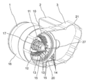
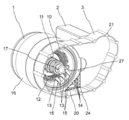
- FIG. 1 shows the configuration of the electric system of the first embodiment
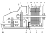
- FIG. 2 shows a cross section of the electric system of the first embodiment in the transverse direction.
- the electric system of this embodiment is composed of a motor 1, an inverter 2 arranged adjacent to the motor 1, and a gear assembly 3 arranged in the output direction of the motor 1.
- a rotor 11 is arranged on the inner peripheral side of the stator 10, and a winding 12 is wound around the stator 10.
- the type of the motor 1 may be a permanent magnet motor having a permanent magnet, a synchronous motor having a field winding, an induction motor having a cage-shaped conductor, a reluctance motor formed only by a rotor core, or the like, and a magnetic field is generated from the rotor.
- the components to be generated and their shapes are not limited.
- the stator 10 is fixed to the inner peripheral side of the frame 16 by shrink fitting or the like.
- the frame 16 is formed by low-pressure casting, die casting, or the like, and its shape and dimensions are not limited, including the bracket that supports the bearing.
- the winding 12 is composed of distributed winding or concentrated winding, and the winding 12 may be composed of either a square wire or a round wire, and the winding method and type of the winding are not limited.
- the switching element of the inverter unit of the inverter 2 may be an IGBT, SiC, or the like, and the type and shape thereof are not limited.
- the motor input terminal 13 drawn out from the winding 12 is connected to an intermediate conductor 15 connected to the inverter output terminal 14, and by applying a current and a voltage from the inverter 2, a current flows through the winding 12 and at the same time. A rotating magnetic field is generated, and the rotor 11 is rotated to generate a torque.
- the gear assembly 3 is connected to the rotor 11 through the shaft 17, and the vehicle is driven by connecting the gear output shaft 23 inside the gear assembly 3 to the axle.
- the shaft 17 is formed of a hollow shaft in FIG. 1, it may be a solid shaft, and its shape and dimensions are not limited.
- the gear assembly 3 is configured by arranging a plurality of gears 22 inside the gearbox 21, and the gear ratio of the gear assembly 3 is configured so as to reduce the rotation speed of the motor 1.
- the gear is composed of parallel shaft spur gears, but the gear may be a planetary gear alone or a combination of planetary gears and spur gears, and the configuration and gear ratio of parallel shafts or uniaxial gears are not limited.
- a differential gear is usually arranged between the gear assembly 3 and the axle.
- an oil-based medium stays in the lower part of the motor 1 and the gear assembly 3, and the oil-based medium can communicate between the motor 1 and the gear assembly 3.
- the immersion portion 20 is provided at a position on the lower side closer to the ground side of the top and bottom than the oil level of the oil-based medium of the motor 1.
- the immersion portion 20 is arranged in the motor 1 on the side closer to the gear assembly 3.
- the dipping portion 20 communicates with the connection hole 27 provided in the frame 16.
- the intermediate conductor 15 is provided so as to connect the motor input terminal 13 and the inverter output terminal 14, and is arranged in the immersion portion 20 through the connection hole 27 provided in the frame 16.
- the immersion portion 20 is arranged at a position on the lower side closer to the ground side of the top and bottom than the oil level of the oil-based medium of the motor 1, but its height and peripheral shape are not limited.
- the intermediate conductor 15 is arranged so as to come into contact with the oil-based medium in the dipping portion 20 (preferably, the intermediate conductor 15 is immersed in the oil-based medium in the dipping portion 20), a part or all of the intermediate conductor 15 is also arranged. It will be placed in an oil-based medium. Further, a part of the gears 22 in the gear assembly 3 is also immersed in the oil-based medium, and the gears 22 are lubricated with each other as they rotate. When the motor 1 is driven, the intermediate conductor 15 is energized by the inverter 2, so Joule heat is generated.
- the oil-based medium is heated by the Joule heat generated in the intermediate conductor 15, and the viscosity of the oil-based medium is lowered. Further, by arranging the intermediate conductor 15 on the side closer to the gear assembly 3 of the motor 1, the distance between the intermediate conductor 15 and the gear 22 of the gear assembly 3 becomes closer than when the intermediate conductor 15 is arranged on the far side, so that the viscosity is increased.
- the reduced oil medium is used to lubricate the gear 22 faster. As a result, the viscous resistance of the oil-based medium at the time of starting is reduced, and the lubrication of the gear 22 of the gear assembly 3 is improved. Therefore, the influence of the efficiency decrease due to the viscous resistance can be reduced, and the electricity cost of the electric system can be improved.
- the intermediate conductor 15 is immersed in an oil-based medium during normal operation, an oil cooling effect can be obtained, and a cooling effect due to heat conduction from the intermediate conductor 15 and the intermediate conductor 15 to the winding 12 can be obtained, and the motor.
- the cooling performance of 1 can be improved.
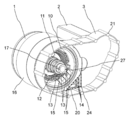
- Fig. 3 shows the configuration of the electric system of Example 2.
- the description of the configuration having the same function as that of the above-described embodiment will be omitted, and different configurations will be mainly described.
- the communication portion 24 that communicates the motor 1 and the gear assembly 3 is provided at a position that overlaps with the immersion portion 20 when viewed from the rotation axis direction of the electric system.
- the motor 1 and the gear assembly 3 are communicated with each other in order to introduce the oil-based medium into the motor 1.
- An oil-based medium is communicated with 3. Therefore, the oil-based medium heated by the intermediate conductor 15 flows from the immersion portion 20 to the gear assembly 3 and the motor 1 through the communication portion 24.
- the communication portion 24 makes the surface of the oil-based medium in the gear assembly 3 equal to the surface of the oil-based medium in the immersion portion 20.
- the gear 22 is arranged.
- the distance between the conductor 15 and the intermediate conductor 15 in the height direction is shortened, and the time until the viscous resistance of the oil-based medium used for lubricating the gear 22 is reduced is shortened, so that the electricity cost can be improved.
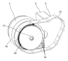
- Fig. 4 shows the configuration of the electric system of Example 3.
- the description of the configuration having the same function as that of the above-described embodiment will be omitted, and different configurations will be mainly described.
- the outer diameter of the first-stage gear 22 is drawn to be slightly smaller than the inner peripheral surface of the gearbox 21, but the size of the gear 22 is the size shown in FIG. 4 if the diameter is applicable. Not limited to. Similarly, the number of teeth of the gear 22 is not limited to the number of teeth shown in FIG. 4 as long as it is an applicable number.
- the oil-based medium that has flowed into the gear assembly 3 from the immersion portion 20 lubricates the gear 22 of the gear assembly 3.
- the gear 22 of the gear assembly 3 since the gear 22 of the gear assembly 3 has an action of lifting the oil-based medium upward, the oil-based medium is diffused to all the gears 22 in the gear assembly 3 that are not immersed in the oil-based medium, and the oil-based medium is diffused to all the gears 22 of the gear assembly 3. All gears 22 can be lubricated. Further, since the pumped oil-based medium diffuses into the motor 1, the oil-based medium cools the winding 12 and the bearing of the motor 1, and the cooling performance of the winding 12 and the bearing can be improved.
- FIG. 5 shows a cross section of the electric system according to the fourth embodiment of the present invention.
- the description of the configuration having the same function as that of the above-described embodiment will be omitted, and different configurations will be mainly described.
- the maximum oil level height of the oil-based medium is set to be equal to or less than the height of the gap surface between the stator 10 and the rotor 11.
- FIG. 6 shows the configuration of the electric system of the fifth embodiment
- FIG. 7 shows a cross section of the electric system of the fifth embodiment in the transverse direction.
- the description of the configuration having the same function as that of the above-described embodiment will be omitted, and different configurations will be mainly described.
- the oil-based medium is scooped up by the gear 22 of the gear assembly 3 inside the gearbox 21, but the oil-based medium is also on the inner peripheral surface 211 of the gearbox. adhere to.
- the inner peripheral surface 211 of the gearbox gradually decreases toward the motor 1, that is, the thickness of the gearbox 21 increases toward the motor 1 side and becomes tapered, and the inner upper surface of the gearbox 21 is on the motor 1 side. Is low.
- the oil-based medium adhering to the inner peripheral surface 211 of the gearbox easily flows to the motor 1 side, the amount of the oil-based medium used for cooling the windings 12 and the bearings increases, and the cooling performance of the windings 12 and the bearings increases. Can be improved.
- the oil-based medium used to cool the windings 12 and bearings returns to the gear assembly 3 side through the immersion portion 20 from the connection hole (not shown) through which the motor input terminal 13 passes, and the oil-based medium circulates in the electric system. It has become.
- FIGS. 8 and 9 show the configuration of the electric system of Example 6, and FIG. 10 shows a cross section of the electric system of Example 6.
- the description of the configuration having the same function as that of the above-described embodiment will be omitted, and different configurations will be mainly described.
- the motor 1 has obtained cooling performance by flowing or immersing an oil-based medium in the coil end 121, and the coil end 121 is also present on the side far from the gear assembly 3.
- the oil-based medium scooped up by the gear 22 inside the gearbox 21 is transferred to the motor 1. It can flow to the gear assembly 3 and the coil end 122 on the far side, and the cooling performance of the winding 12 can be improved.
- the oil-based medium can also be used for cooling the gear assembly 3 and the bearing on the distant side.
- the oil-based medium can be returned to the gear assembly 3 of the motor 1 from the distant side and the entire electric system.
- the oil-based medium can circulate.
- the oil passage a25 is provided between the motor 1 and the inverter 2 in FIG. 8, it may be provided on the top side (upper side) of the top and bottom of the motor 1 or on the opposite side of the motor 1 from the inverter 2. It is not limited to the position described in 8. In FIG. 8, one side wall is removed so that the oil passage a25 can be seen, but the pipeline is actually formed.
- the oil passage b26 shown in FIG. 9 is also provided between the motor 1 and the inverter 2, but may be provided on the opposite side of the motor 1 from the inverter 2, and the position is not limited to the position shown in FIG. In FIG. 9, the lower surface of the oil passage b is shown so as to be visible, and the pipeline is actually formed inside.
- the shapes of the oil passages a25 and the oil passages b26 are not the shapes shown in FIGS. 8 and 9, and may be cylindrical as long as the pipeline is formed, and are not particularly limited.
- FIG. 11 shows the configuration of the electric system of the seventh embodiment.
- the description of the configuration having the same function as that of the above-described embodiment will be omitted, and different configurations will be mainly described.
- a water channel 18 passing through the inside of the frame 16 provided on the outer peripheral side of the motor 1 is provided.
- the water channel 18 is not spiral as shown in FIG. 11, but may have a simple folded shape, and its flow path, shape, and area are not limited.
- FIG. 12 shows the configuration of the electric system of Example 8.
- the description of the configuration having the same function as that of the above-described embodiment will be omitted, and different configurations will be mainly described.
- the intermediate conductor 15 is integrally configured with the inverter output terminal 14.
- FIG. 13 shows the configuration of the electric system of the ninth embodiment.
- the description of the configuration having the same function as that of the above-described embodiment will be omitted, and different configurations will be mainly described.
- the intermediate conductor 15 is integrated with the motor input terminal 13.
- the number of parts connecting the motor 1 and the inverter 2 can be reduced, the man-hours for connection can be reduced, and the manufacturing cost of the electric system can be reduced, as in the case of the eighth embodiment. Can be suppressed.
- FIG. 14 shows the configuration of the electric system of Example 10.
- the description of the configuration having the same function as that of the above-described embodiment will be omitted, and different configurations will be mainly described.
- the motor 1 and the gear assembly 3 communicate with each other via the immersion portion 20 and the communication portion 24.
- the connection hole 27 of the frame 16 in which the motor input terminal 13 and the intermediate conductor 15 are arranged is directly communicated with the gear assembly 3.
- the intermediate conductor 15 can be assembled to the frame 16 in a state of being connected to the motor input terminal 13, and workability at the time of assembling the electric system can be improved.
- the present invention is not limited to the above-described embodiment, and includes various modifications and equivalent configurations within the scope of the attached claims.
- the above-described examples have been described in detail in order to explain the present invention in an easy-to-understand manner, and the present invention is not necessarily limited to those having all the described configurations.
- a part of the configuration of one embodiment may be replaced with the configuration of another embodiment.
- the configuration of another embodiment may be added to the configuration of one embodiment.
- other configurations may be added / deleted / replaced with respect to a part of the configurations of each embodiment.
Landscapes
- Engineering & Computer Science (AREA)
- Power Engineering (AREA)
- General Engineering & Computer Science (AREA)
- Mechanical Engineering (AREA)
- Chemical & Material Sciences (AREA)
- Combustion & Propulsion (AREA)
- Transportation (AREA)
- Motor Or Generator Cooling System (AREA)
- Connection Of Motors, Electrical Generators, Mechanical Devices, And The Like (AREA)
- Arrangement Or Mounting Of Propulsion Units For Vehicles (AREA)
- General Details Of Gearings (AREA)
- Insulation, Fastening Of Motor, Generator Windings (AREA)
Abstract
本発明の課題は、始動時における油性媒体の粘性抵抗を低減でき、通常運転時におけるモータの冷却性能を向上することである。 ステータとロータを有するモータ部と、前記ステータの巻線に電力を供給するインバータ部と、前記ロータから出力される回転を減速するギア部と、前記ギア部内を流動する油性媒体が滞留する浸漬部と、前記巻線と前記インバータ部との間で電力を伝達する中間導体と、を備え、前記中間導体の少なくとも一部は、前記浸漬部において前記油性媒体と接している。
Description
本発明は,車両用駆動装置の電動システムに関する。
近年,車両駆動用装置としてモータの活用が拡大している。車両駆動用装置としてのモータはインバータによって駆動され,モータの出力軸端に配置されたギアを通じて、車両を駆動する。ギアはモータの回転速度を減速して、モータトルクを車軸に伝える機能を有する。ギア内の歯車は油によって潤滑されているが、寒冷地など、低温環境下においては、始動時に潤滑油の温度が低く、潤滑油の粘性が高い。これにより、モータは大きな駆動用トルクの発生が必要となるため、大電流を流す必要がある。従って、モータの効率が低下し、車両の電費が低下する課題がある。また、通常運転時は、モータに巻装されている巻線やインバータと接続しているバスバーなどが発熱するため、始動時とは異なり、これらを効率的に冷却する必要がある。
これらの課題に対する本技術分野の背景技術として、特許文献1(特開2014-189036号公報)がある。特許文献1には、車輪内に配置されるモータケースに収納され、車軸と連動しているロータと前記モータケースに固定されるステータとを有する電気モータと、該電気モータと電気的に連結し、コンデンサとスイッチング素子からなるパワーモジュールとを有するインバータユニットと、を備えてなる車両用推進装置において、前記モータケースに、前記電気モータを潤滑・冷却するオイルが油密状に収納され、前記モータケースの前記車軸と反対側の側面に、前記パワーモジュールが前記モータケース内のオイル溜りに対応する位置になるように前記インバータユニットを取付けてなる、ことを特徴とする車両用推進装置が開示されている(請求項1参照)。
前述した特許文献1に開示された車両用推進装置は、モータケース内に配置されている油の油面以下にインバータのパワーモジュールを配置するものであり、モータ冷却及びプラネタリギヤの潤滑用の油でインバータのパワーモジュールを冷却し、インホイールモータを小さな形状で高い冷却性能を得ている。しかしながら、ギアがモータのロータ内部に配置されており、モータとインバータの間のバスバーや巻線などの発熱部から距離があり、始動時における油の粘性低下の影響を軽減できない。また、モータのロータに接続された油跳ね上げ片によって掻き揚げられたギア潤滑用の油を、モータ巻線の冷却及びギア歯車の潤滑に使用するため、通常運転時は、回転速度に応じて油掻き揚げ時の摩擦損が大きくなり、効率の低下や冷却性能の向上効果が低下する。
本願において開示される発明の代表的な一例を示せば以下の通りである。すなわち、電動システムであって、ステータとロータを有するモータ部と、前記ステータの巻線に電力を供給するインバータ部と、前記ロータから出力される回転を減速するギア部と、前記ギア部内を流動する油性媒体が滞留する浸漬部と、前記巻線と前記インバータ部との間で電力を伝達する中間導体と、を備え、前記中間導体の少なくとも一部は、前記浸漬部において前記油性媒体と接している。
本発明によれば、始動時における油性媒体の粘性抵抗を低減でき、通常運転時におけるモータの冷却性能を向上できる。前述した以外の課題、構成及び効果は、以下の実施例の説明によって明らかにされる。
以下、図面を参照して、本発明の実施例を詳細に説明する。
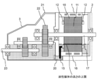
<実施例1> 図1に実施例1の電動システムの構成を示し、図2に実施例1の電動システムの横方向断面を示す。
本実施例の電動システムは、モータ1と、その隣り合う位置に配置されたインバータ2と、モータ1の出力方向に配置されるギアアセンブリ3によって構成される。モータ1はステータ10の内周側にロータ11が配置され、ステータ10には巻線12が巻装される。モータ1の種類は、永久磁石を有する永久磁石電動機、界磁巻線を有する同期電動機、かご形導体を有する誘導電動機、回転子コアだけで形成されるリラクタンスモータなどでもよく、回転子から磁界を発生させるための構成部品やその形状は限定されない。ステータ10はフレーム16の内周側に焼嵌めなどによって固定される。フレーム16は低圧鋳造やダイカストなどで形成され、軸受を支えるブラケットを含め、その形状や寸法は限定されない。巻線12は分布巻や集中巻で構成され、巻線12は角線又は丸線どちらで構成してもよく、巻線の巻き方や種類は限定されない。
インバータ2のインバータユニットのスイッチング素子はIGBTやSiCなどでもよく、その種類や形状は限定されない。巻線12から引き出されたモータ入力端子13は、インバータ出力端子14に接続された中間導体15に接続されており、インバータ2から電流、電圧を印加することによって、巻線12に電流が流れるとともに回転磁界が発生し、ロータ11を回転させてトルクを発生する。ロータ11はシャフト17を通じてギアアセンブリ3が接続されており、このギアアセンブリ3内部のギア出力軸23が車軸と接続されることによって、車両が駆動する。図1ではシャフト17は中空シャフトで形成されているが、中実シャフトでもよく、その形状や寸法は限定されない。
ギアアセンブリ3は、ギアボックス21の内部に複数の歯車22が配置されて構成されており、モータ1の回転速度を減速するようにギアアセンブリ3のギア比が構成されている。図1、図2ではギアは平行軸の平歯車で構成されているが、歯車は遊星歯車単体又は遊星歯車と平歯車の組み合わせでもよく、並行軸か一軸かの構成やギア比は限定されない。また、図中には記載しないが、通常はギアアセンブリ3と車軸との間にデファレンシャルギヤが配置される。
図2に灰色で示すように、モータ1及びギアアセンブリ3内の下部には油性媒体が滞留しており、モータ1とギアアセンブリ3との間で油性媒体が連通可能となっている。図1、図2に示すように、モータ1の油性媒体の油面よりも天地の地側に近い下側の位置には浸漬部20が設けられる。浸漬部20は、モータ1においてギアアセンブリ3に近い側に配置される。浸漬部20は、フレーム16に設けられた接続穴27と連通している。中間導体15は、モータ入力端子13とインバータ出力端子14とを接続するように設けられており、フレーム16に設けられた接続穴27を通過して浸漬部20内に配置される。浸漬部20はモータ1の油性媒体の油面よりも天地の地側に近い下側の位置に配置されるが、その高さや周辺形状は限定されない。
中間導体15は浸漬部20内の油性媒体に触れるように(望ましくは、中間導体15は浸漬部20内の油性媒体に浸漬するように)配置されるため、中間導体15の一部又は全ても油性媒体の中に配置されることとなる。また、ギアアセンブリ3内の歯車22の一部も油性媒体に浸漬され、歯車22は自身の回転に伴って歯車同士の潤滑がなされる。中間導体15は、モータ1が駆動する際、インバータ2によって通電されるためジュール熱が発生する。そのため、特にモータ1の始動時において、中間導体15で発生するジュール熱によって油性媒体が加熱され、油性媒体の粘性が低下する。また、中間導体15をモータ1のギアアセンブリ3に近い側に配置することによって、遠い側に配置した場合に比べて、中間導体15とギアアセンブリ3の歯車22との距離が近くなるため、粘性が低下した油性媒体がより早く歯車22の潤滑に使用される。これにより、始動時の油性媒体の粘性抵抗が低減し、ギアアセンブリ3の歯車22の潤滑が改善される。従って、粘性抵抗に伴う効率低下の影響を低減でき、電動システムの電費が改善できる。
一方、通常運転時には中間導体15が油性媒体に浸漬されるため、油冷の効果を得ることができ、中間導体15及び中間導体15から巻線12への熱伝導による冷却効果が得られ、モータ1の冷却性能を向上できる。
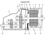
<実施例2> 図3に実施例2の電動システムの構成を示す。実施例2では、前述した実施例と同じ機能を有する構成の説明は省略し、主に異なる構成について説明する。
本実施例の電動システムでは、モータ1とギアアセンブリ3を連通する連通部24が、電動システムの回転軸方向から見た場合に、浸漬部20と重なる位置に設けられる。なお、実施例1でもモータ1に油性媒体を導入するために、モータ1とギアアセンブリ3とは連通しているが、実施例では連通部24を設けて、より広い面積でモータ1とギアアセンブリ3との間で油性媒体を連通させている。このため、中間導体15によって加熱された油性媒体は連通部24を通じて浸漬部20からギアアセンブリ3及びモータ1に流れる。
連通部24によって、ギアアセンブリ3内の油性媒体の表面と浸漬部20内の油性媒体の表面とが等しい高さになる。中間導体15は浸漬部20にの油性媒体に触れるように(例えば、浸漬するように)配置され、ギアアセンブリ3の歯車22の少なくとも下端は油性媒体に浸漬するように配置されるので、歯車22と中間導体15との高さ方向の距離が近くなり、歯車22の潤滑に使用される油性媒体の粘性抵抗が軽減されるまでの時間が短くなり、電費を向上できる。
連通部24によって、ギアアセンブリ3内の油性媒体の表面と浸漬部20内の油性媒体の表面とが等しい高さになる。中間導体15は浸漬部20にの油性媒体に触れるように(例えば、浸漬するように)配置され、ギアアセンブリ3の歯車22の少なくとも下端は油性媒体に浸漬するように配置されるので、歯車22と中間導体15との高さ方向の距離が近くなり、歯車22の潤滑に使用される油性媒体の粘性抵抗が軽減されるまでの時間が短くなり、電費を向上できる。
<実施例3> 図4に実施例3の電動システムの構成を示す。実施例3では、前述した実施例と同じ機能を有する構成の説明は省略し、主に異なる構成について説明する。
図4では一段目の歯車22の外径がギアボックス21の内周面よりわずかに小さい程度で描かれているが、歯車22の大きさは適用可能な径であれば図4に記載の大きさに限定されない。同様に、歯車22の歯数も適用可能な数であれば図4に記載の歯数に限定されない。本実施例の電動システムでは、浸漬部20からギアアセンブリ3に流れこんだ油性媒体はギアアセンブリ3の歯車22を潤滑する。それと同時に、ギアアセンブリ3の歯車22は油性媒体を上方向に掻き揚げる作用を持つため、油性媒体に浸漬されていないギアアセンブリ3内の全ての歯車22に油性媒体を拡散させ、ギアアセンブリ3の全ての歯車22を潤滑できる。また、掻き揚げられた油性媒体がモータ1へ拡散するので、油性媒体がモータ1の巻線12や軸受が冷却され、巻線12や軸受の冷却性能を向上できる。
<実施例4> 図5に本発明の実施例4の電動システムの横方向断面を示す。実施例4では、前述した実施例と同じ機能を有する構成の説明は省略し、主に異なる構成について説明する。
本実施例の電動システムでは、図5に灰色で示すように油性媒体の最大油面高さをステータ10とロータ11のギャップ面の高さ以下としている。油性媒体の油面高さを油性媒体がロータ11に触れない高さとすることによって、通常運転時に油性媒体のロータ11への付着を防止でき、ステータ10とロータ11との間のギャップに付着した油性媒体によってロータ11に発生する回転摩擦損を抑制できる。また、巻線12が油性媒体に浸漬されることによって、通常運転時に巻線12が油冷され、巻線12の冷却性能を向上できる。
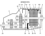
<実施例5> 図6に実施例5の電動システムの構成を示し、図7に実施例5の電動システムの横方向断面を示す。実施例5では、前述した実施例と同じ機能を有する構成の説明は省略し、主に異なる構成について説明する。
本実施例の電動システムでは、図6及び図7に示すように、ギアボックス21の内部ではギアアセンブリ3の歯車22によって油性媒体が掻き揚げられるが、油性媒体はギアボックス内周面211にも付着する。ギアボックス内周面211がモータ1側に向かうにつれて漸減する、すなわち、モータ1側に向かうほどギアボックス21の厚みが増加してテーパ状になっており、ギアボックス21の内側上面がモータ1側で低くなっている。これにより、ギアボックス内周面211に付着した油性媒体がモータ1側に流れやすくなり、巻線12や軸受の冷却に使用される油性媒体の量が増加し、巻線12や軸受の冷却性能を向上できる。巻線12や軸受の冷却に使用された油性媒体はモータ入力端子13が通過する接続穴(図示省略)から浸漬部20を通じてギアアセンブリ3側へ戻り、油性媒体は電動システム内で循環する構成となっている。
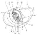
<実施例6> 図8及び図9に実施例6の電動システムの構成、図10に実施例6の電動システムの横方向断面を示す。実施例6では、前述した実施例と同じ機能を有する構成の説明は省略し、主に異なる構成について説明する。
モータ1は、コイルエンド121に油性媒体が流れる又は浸漬されることで、冷却性能を得ており、コイルエンド121はギアアセンブリ3から遠い側にも存在する。本実施例の電動システムでは、ギアアセンブリ3からモータ1のギアアセンブリ3と遠い側に通じる油路a25を設けることによって、ギアボックス21の内部で歯車22によって掻き揚げられた油性媒体をモータ1のギアアセンブリ3と遠い側のコイルエンド122まで流すことができ、巻線12の冷却性能を向上できる。また、ギアアセンブリ3と遠い側の軸受の冷却用としても油性媒体を活用できる。
さらに、モータ1のギアアセンブリ3と遠い側からギアアセンブリ3に通じる油路b26を設けることによって、モータ1のギアアセンブリ3と遠い側からギアアセンブリ3に油性媒体を戻すことができ、電動システム全体を油性媒体が循環できる。
なお、図8では、油路a25はモータ1とインバータ2の間に設けているが、モータ1の天地の天側(上側)やモータ1のインバータ2と逆側などに設けてもよく、図8に記載の位置に限定されない。なお、図8においては、油路a25が見えるように一方の側壁を除去して図示しているが、実際には管路が形成されている。同様に図9に記載の油路b26も、モータ1とインバータ2の間に設けているが、モータ1のインバータ2と逆側などに設けてもよく、図9に記載の位置に限定されない。なお、図9においては、油路bの下面が見えるように図示しており、実際には内部に管路が形成されている。また油路a25及び油路b26の形状は図8及び図9に記載の形状ではなく、管路が形成されれば円筒形などでもよく、特に限定されない。
<実施例7> 図11に実施例7の電動システムの構成を示す。実施例7では、前述した実施例と同じ機能を有する構成の説明は省略し、主に異なる構成について説明する。
本実施例の電動システムでは、モータ1の外周側に設けられたフレーム16の内部を通る水路18が設けられている。水路18は図11に示すらせん状ではなく、単純な折り返し形状でもよく、その流路や形状や面積は限定されない。水路18の中に冷却用の冷媒を流すことで、フレーム16及びステータ10のコアを通じてモータ1の巻線12を冷却することができ、通常運転時のモータ1の巻線12の発熱を抑制できる。また、フレーム16全体を冷却でき、通常運転時の油性媒体の冷却やフレーム16に取り付けられた軸受などの冷却も可能となる。
<実施例8> 図12に実施例8の電動システムの構成を示す。実施例8では、前述した実施例と同じ機能を有する構成の説明は省略し、主に異なる構成について説明する。
本実施例の電動システムでは、中間導体15がインバータ出力端子14と一体に構成されている。これにより、モータ1とインバータ2を接続する部品を削減でき、接続のための工数を低減でき、電動システムの製造コストを抑制できる。
<実施例9> 図13に実施例9の電動システムの構成を示す。実施例9では、前述した実施例と同じ機能を有する構成の説明は省略し、主に異なる構成について説明する。
本実施例の電動システムでは、中間導体15がモータ入力端子13と一体化されている。中間導体15がモータ入力端子13と一体化されることによって、実施例8と同様に、モータ1とインバータ2を接続する部品を削減でき、接続のための工数を低減でき、電動システムの製造コストを抑制できる。
<実施例10> 図14に実施例10の電動システムの構成を示す。実施例10では、前述した実施例と同じ機能を有する構成の説明は省略し、主に異なる構成について説明する。
前述した実施例では、モータ1とギアアセンブリ3が浸漬部20及び連通部24を介して連通している。本実施例の電動システムでは、モータ入力端子13及び中間導体15が配置されるフレーム16の接続穴27がギアアセンブリ3と直接連通している。これにより、中間導体15をモータ入力端子13に接続した状態でフレーム16に組み付けることができ、電動システムの組立時の作業性を向上できる。
なお、本発明は前述した実施例に限定されるものではなく、添付した特許請求の範囲の趣旨内における様々な変形例及び同等の構成が含まれる。例えば、前述した実施例は本発明を分かりやすく説明するために詳細に説明したものであり、必ずしも説明した全ての構成を備えるものに本発明は限定されない。また、ある実施例の構成の一部を他の実施例の構成に置き換えてもよい。また、ある実施例の構成に他の実施例の構成を加えてもよい。
また、各実施例の構成の一部について、他の構成の追加・削除・置換をしてもよい。
また、各実施例の構成の一部について、他の構成の追加・削除・置換をしてもよい。
1…モータ、2…インバータ、3…ギア、10…ステータ、11…ロータ、12…巻線、121…コイルエンド、13…モータ入力端子、14…インバータ出力端子、15…中間導体、16…フレーム、17…シャフト、18…水路、20…浸漬部、21…ギアボックス、22…歯車、23…ギア出力軸、24… 連通部、25…油路a、26…油路b、27…接続穴
Claims (11)
- 電動システムであって、
ステータとロータを有するモータ部と、
前記ステータの巻線に電力を供給するインバータ部と、
前記ロータから出力される回転を減速するギア部と、
前記ギア部内を流動する油性媒体が滞留する浸漬部と、
前記巻線と前記インバータ部との間で電力を伝達する中間導体と、を備え、
前記中間導体の少なくとも一部は、前記浸漬部において前記油性媒体と接している電動システム。 - 請求項1に記載の電動システムであって、
前記浸漬部は、前記モータ部側の前記油性媒体の油面より下方であって、前記ギア部に近い側の前記巻線の近傍に配置され、
前記油性媒体は、前記モータ部と前記ギア部とを連通して流動する電動システム。 - 請求項1に記載の電動システムであって、
前記モータ部と前記ギア部とを連通する連通部を備え、
前記連通部は、前記ロータの回転軸方向から見た場合、前記浸漬部と重なる位置に設けられる電動システム。 - 請求項1に記載の電動システムであって、
前記ギア部は、歯車の回転によって、前記油性媒体を上方向に上げる電動システム。 - 請求項1に記載の電動システムであって、
前記油性媒体の油面の高さが、前記モータ部の前記ロータに触れない高さである電動システム。 - 請求項1に記載の電動システムであって、
前記ギア部を構成するギアボックスの内側上面が前記ギア部から前記モータ部へ向かうにつれて低くなる電動システム。 - 請求項4に記載の電動システムであって、
前記ギア部から前記モータ部の前記ギア部に遠い側へ前記油性媒体を流入させる第1油路と、
前記モータ部の前記ギア部に遠い側から前記ギア部へ前記油性媒体を流入させる第2油路とを備える電動システム。 - 請求項1に記載の電動システムであって、
前記モータ部のフレームは水路を有する電動システム。 - 請求項1に記載の電動システムであって、
前記中間導体と前記インバータ部の出力端子とが一体に形成されている電動システム。 - 請求項1に記載の電動システムであって、
前記中間導体と前記モータ部の入力端子とが一体に形成されている電動システム。 - 請求項1に記載の電動システムであって、
前記モータ部は、入力端子が配置されるフレームを有し、
前記フレームの接続穴が、前記ギア部と連通している電動システム。
Applications Claiming Priority (2)
| Application Number | Priority Date | Filing Date | Title |
|---|---|---|---|
| JP2019-160465 | 2019-09-03 | ||
| JP2019160465A JP7432326B2 (ja) | 2019-09-03 | 2019-09-03 | 電動システム |
Publications (1)
| Publication Number | Publication Date |
|---|---|
| WO2021044809A1 true WO2021044809A1 (ja) | 2021-03-11 |
Family
ID=74846930
Family Applications (1)
| Application Number | Title | Priority Date | Filing Date |
|---|---|---|---|
| PCT/JP2020/030549 Ceased WO2021044809A1 (ja) | 2019-09-03 | 2020-08-11 | 電動システム |
Country Status (2)
| Country | Link |
|---|---|
| JP (1) | JP7432326B2 (ja) |
| WO (1) | WO2021044809A1 (ja) |
Cited By (6)
| Publication number | Priority date | Publication date | Assignee | Title |
|---|---|---|---|---|
| DE102022102854A1 (de) | 2022-02-08 | 2023-08-10 | Schaeffler Technologies AG & Co. KG | Elektrisch betreibbarer Achsantriebsstrang |
| EP4297252A1 (en) * | 2022-06-20 | 2023-12-27 | Valeo eAutomotive Germany GmbH | Electric drive assembly system, vehicle and assembly method of electric drive assembly system |
| EP4297253A1 (en) * | 2022-06-20 | 2023-12-27 | Valeo eAutomotive Germany GmbH | Electric drive assembly system, vehicle and method for assembling electric drive assembly system |
| JP2024179079A (ja) * | 2023-06-14 | 2024-12-26 | トヨタ自動車株式会社 | 駆動装置 |
| EP4438366A4 (en) * | 2022-03-30 | 2025-04-16 | BYD Company Limited | VEHICLE TRANSMISSION, DRIVE ARRANGEMENT AND VEHICLE |
| US20250192641A1 (en) * | 2023-12-07 | 2025-06-12 | Valeo Eautomotive Germany Gmbh | Housing assembly, electric drive device and vehicle |
Families Citing this family (1)
| Publication number | Priority date | Publication date | Assignee | Title |
|---|---|---|---|---|
| WO2023039333A1 (en) * | 2021-09-07 | 2023-03-16 | Atieva, Inc. | Multi-motor electric-vehicle drive units |
Citations (7)
| Publication number | Priority date | Publication date | Assignee | Title |
|---|---|---|---|---|
| JP2008263757A (ja) * | 2007-04-13 | 2008-10-30 | Toyota Motor Corp | 駆動装置 |
| JP2011004487A (ja) * | 2009-06-17 | 2011-01-06 | Honda Motor Co Ltd | 電動機 |
| JP2012060785A (ja) * | 2010-09-09 | 2012-03-22 | Toyota Motor Corp | 車両用駆動装置の冷却構造 |
| JP2012217303A (ja) * | 2011-04-01 | 2012-11-08 | Honda Motor Co Ltd | 車両用駆動装置 |
| JP2014225970A (ja) * | 2013-05-16 | 2014-12-04 | 本田技研工業株式会社 | 電動機 |
| JP2016116294A (ja) * | 2014-12-12 | 2016-06-23 | 富士重工業株式会社 | バスバーユニット |
| JP2018179127A (ja) * | 2017-04-12 | 2018-11-15 | 株式会社Subaru | 潤滑油昇温装置及び潤滑油昇温方法 |
Family Cites Families (4)
| Publication number | Priority date | Publication date | Assignee | Title |
|---|---|---|---|---|
| JP4485566B2 (ja) | 2007-11-13 | 2010-06-23 | 本田技研工業株式会社 | モータ式動力装置 |
| JP5256117B2 (ja) | 2009-05-15 | 2013-08-07 | 本田技研工業株式会社 | モータユニット |
| JP2012138989A (ja) | 2010-12-24 | 2012-07-19 | Toyota Motor Corp | 動力伝達装置 |
| JP7434716B2 (ja) | 2019-03-11 | 2024-02-21 | 株式会社デンソー | 電動駆動装置 |
-
2019
- 2019-09-03 JP JP2019160465A patent/JP7432326B2/ja active Active
-
2020
- 2020-08-11 WO PCT/JP2020/030549 patent/WO2021044809A1/ja not_active Ceased
Patent Citations (7)
| Publication number | Priority date | Publication date | Assignee | Title |
|---|---|---|---|---|
| JP2008263757A (ja) * | 2007-04-13 | 2008-10-30 | Toyota Motor Corp | 駆動装置 |
| JP2011004487A (ja) * | 2009-06-17 | 2011-01-06 | Honda Motor Co Ltd | 電動機 |
| JP2012060785A (ja) * | 2010-09-09 | 2012-03-22 | Toyota Motor Corp | 車両用駆動装置の冷却構造 |
| JP2012217303A (ja) * | 2011-04-01 | 2012-11-08 | Honda Motor Co Ltd | 車両用駆動装置 |
| JP2014225970A (ja) * | 2013-05-16 | 2014-12-04 | 本田技研工業株式会社 | 電動機 |
| JP2016116294A (ja) * | 2014-12-12 | 2016-06-23 | 富士重工業株式会社 | バスバーユニット |
| JP2018179127A (ja) * | 2017-04-12 | 2018-11-15 | 株式会社Subaru | 潤滑油昇温装置及び潤滑油昇温方法 |
Cited By (12)
| Publication number | Priority date | Publication date | Assignee | Title |
|---|---|---|---|---|
| DE102022102854A1 (de) | 2022-02-08 | 2023-08-10 | Schaeffler Technologies AG & Co. KG | Elektrisch betreibbarer Achsantriebsstrang |
| WO2023151738A1 (de) * | 2022-02-08 | 2023-08-17 | Schaeffler Technologies AG & Co. KG | Elektrisch betreibbarer achsantriebsstrang |
| DE102022102854B4 (de) | 2022-02-08 | 2023-12-07 | Schaeffler Technologies AG & Co. KG | Elektrisch betreibbarer Achsantriebsstrang |
| EP4438366A4 (en) * | 2022-03-30 | 2025-04-16 | BYD Company Limited | VEHICLE TRANSMISSION, DRIVE ARRANGEMENT AND VEHICLE |
| AU2023247919B2 (en) * | 2022-03-30 | 2026-02-05 | Byd Company Limited | Vehicle transmission, power assembly and vehicle |
| US12655901B2 (en) | 2022-03-30 | 2026-06-16 | Byd Company Limited | Transmission of vehicle, powertrain, and vehicle with improved oil flow mechanism |
| EP4297252A1 (en) * | 2022-06-20 | 2023-12-27 | Valeo eAutomotive Germany GmbH | Electric drive assembly system, vehicle and assembly method of electric drive assembly system |
| EP4297253A1 (en) * | 2022-06-20 | 2023-12-27 | Valeo eAutomotive Germany GmbH | Electric drive assembly system, vehicle and method for assembling electric drive assembly system |
| US12640617B2 (en) | 2022-06-20 | 2026-05-26 | Valeo Eautomotive Germany Gmbh | Electric drive assembly system, vehicle and method for assembling electric drive assembly system |
| JP2024179079A (ja) * | 2023-06-14 | 2024-12-26 | トヨタ自動車株式会社 | 駆動装置 |
| JP7827017B2 (ja) | 2023-06-14 | 2026-03-10 | トヨタ自動車株式会社 | 駆動装置 |
| US20250192641A1 (en) * | 2023-12-07 | 2025-06-12 | Valeo Eautomotive Germany Gmbh | Housing assembly, electric drive device and vehicle |
Also Published As
| Publication number | Publication date |
|---|---|
| JP2021038801A (ja) | 2021-03-11 |
| JP7432326B2 (ja) | 2024-02-16 |
Similar Documents
| Publication | Publication Date | Title |
|---|---|---|
| JP2021038801A (ja) | 電動システム | |
| US11303174B2 (en) | Rotor for an electric machine | |
| EP2724450A2 (en) | Cooling structure of rotary electric machine | |
| CN111682671B (zh) | 电动驱动装置 | |
| CN109891711B (zh) | 用于异步机的鼠笼式转子 | |
| JP2001190047A (ja) | 電動モータのロータ冷却装置 | |
| US10454344B2 (en) | Rotating electrical machine utilizing cooling liquid supplied to coil end to cool other components | |
| US12132381B2 (en) | Air gap scavenging system for oil cooled electric motor | |
| JP2011142788A (ja) | 電動機の冷却構造 | |
| JP7732515B2 (ja) | 回転電機 | |
| JP5304617B2 (ja) | 電動機の冷却構造 | |
| US20060066168A1 (en) | Bonded rotor laminations | |
| WO2023006217A1 (en) | Electric drive for a motor vehicle | |
| CN115244833B (zh) | 电动系统 | |
| WO2021208972A1 (en) | Drivetrain system for an electrified vehicle | |
| WO2022135082A1 (en) | Drivetrain system for an electrified vehicle | |
| JP3937950B2 (ja) | 両面空隙型回転電機 | |
| KR20210058890A (ko) | 댐퍼를 통합한 연결 슬리브가 구비된 회전 전기 기계 | |
| JP2023551936A (ja) | 電動車両用の一体型駆動系アセンブリ及び電動車両 | |
| US12359717B2 (en) | Vehicle drive device | |
| CN112740516A (zh) | 具有至少一个润滑剂存储槽的旋转电机 | |
| US11146157B2 (en) | Dual rotor electric machine in an automotive application | |
| JP2025144010A (ja) | 電動オイルポンプ | |
| JP6413775B2 (ja) | 回転電機 | |
| CN117203878A (zh) | 旋转电机 |
Legal Events
| Date | Code | Title | Description |
|---|---|---|---|
| 121 | Ep: the epo has been informed by wipo that ep was designated in this application |
Ref document number: 20859858 Country of ref document: EP Kind code of ref document: A1 |
|
| NENP | Non-entry into the national phase |
Ref country code: DE |
|
| 122 | Ep: pct application non-entry in european phase |
Ref document number: 20859858 Country of ref document: EP Kind code of ref document: A1 |