EP4297253A1 - Electric drive assembly system, vehicle and method for assembling electric drive assembly system - Google Patents
Electric drive assembly system, vehicle and method for assembling electric drive assembly system Download PDFInfo
- Publication number
- EP4297253A1 EP4297253A1 EP23180114.3A EP23180114A EP4297253A1 EP 4297253 A1 EP4297253 A1 EP 4297253A1 EP 23180114 A EP23180114 A EP 23180114A EP 4297253 A1 EP4297253 A1 EP 4297253A1
- Authority
- EP
- European Patent Office
- Prior art keywords
- electric machine
- drive assembly
- assembly system
- electric drive
- control module
- Prior art date
- Legal status (The legal status is an assumption and is not a legal conclusion. Google has not performed a legal analysis and makes no representation as to the accuracy of the status listed.)
- Pending
Links
- 238000000034 method Methods 0.000 title claims abstract description 13
- 238000007789 sealing Methods 0.000 claims description 12
- 238000001746 injection moulding Methods 0.000 claims description 3
- 238000001816 cooling Methods 0.000 description 5
- 239000000243 solution Substances 0.000 description 5
- 238000004891 communication Methods 0.000 description 3
- 230000010354 integration Effects 0.000 description 3
- 239000003921 oil Substances 0.000 description 2
- 229910000976 Electrical steel Inorganic materials 0.000 description 1
- 230000000712 assembly Effects 0.000 description 1
- 238000000429 assembly Methods 0.000 description 1
- 230000000994 depressogenic effect Effects 0.000 description 1
- 230000001939 inductive effect Effects 0.000 description 1
- 230000001360 synchronised effect Effects 0.000 description 1
- 238000003466 welding Methods 0.000 description 1
- 238000004804 winding Methods 0.000 description 1
Images
Classifications
-
- H—ELECTRICITY
- H02—GENERATION; CONVERSION OR DISTRIBUTION OF ELECTRIC POWER
- H02K—DYNAMO-ELECTRIC MACHINES
- H02K7/00—Arrangements for handling mechanical energy structurally associated with dynamo-electric machines, e.g. structural association with mechanical driving motors or auxiliary dynamo-electric machines
- H02K7/10—Structural association with clutches, brakes, gears, pulleys or mechanical starters
- H02K7/116—Structural association with clutches, brakes, gears, pulleys or mechanical starters with gears
-
- H—ELECTRICITY
- H02—GENERATION; CONVERSION OR DISTRIBUTION OF ELECTRIC POWER
- H02K—DYNAMO-ELECTRIC MACHINES
- H02K5/00—Casings; Enclosures; Supports
- H02K5/04—Casings or enclosures characterised by the shape, form or construction thereof
- H02K5/22—Auxiliary parts of casings not covered by groups H02K5/06-H02K5/20, e.g. shaped to form connection boxes or terminal boxes
- H02K5/225—Terminal boxes or connection arrangements
-
- B—PERFORMING OPERATIONS; TRANSPORTING
- B60—VEHICLES IN GENERAL
- B60K—ARRANGEMENT OR MOUNTING OF PROPULSION UNITS OR OF TRANSMISSIONS IN VEHICLES; ARRANGEMENT OR MOUNTING OF PLURAL DIVERSE PRIME-MOVERS IN VEHICLES; AUXILIARY DRIVES FOR VEHICLES; INSTRUMENTATION OR DASHBOARDS FOR VEHICLES; ARRANGEMENTS IN CONNECTION WITH COOLING, AIR INTAKE, GAS EXHAUST OR FUEL SUPPLY OF PROPULSION UNITS IN VEHICLES
- B60K1/00—Arrangement or mounting of electrical propulsion units
-
- B—PERFORMING OPERATIONS; TRANSPORTING
- B60—VEHICLES IN GENERAL
- B60K—ARRANGEMENT OR MOUNTING OF PROPULSION UNITS OR OF TRANSMISSIONS IN VEHICLES; ARRANGEMENT OR MOUNTING OF PLURAL DIVERSE PRIME-MOVERS IN VEHICLES; AUXILIARY DRIVES FOR VEHICLES; INSTRUMENTATION OR DASHBOARDS FOR VEHICLES; ARRANGEMENTS IN CONNECTION WITH COOLING, AIR INTAKE, GAS EXHAUST OR FUEL SUPPLY OF PROPULSION UNITS IN VEHICLES
- B60K17/00—Arrangement or mounting of transmissions in vehicles
- B60K17/04—Arrangement or mounting of transmissions in vehicles characterised by arrangement, location, or kind of gearing
- B60K17/06—Arrangement or mounting of transmissions in vehicles characterised by arrangement, location, or kind of gearing of change-speed gearing
-
- B—PERFORMING OPERATIONS; TRANSPORTING
- B60—VEHICLES IN GENERAL
- B60L—PROPULSION OF ELECTRICALLY-PROPELLED VEHICLES; SUPPLYING ELECTRIC POWER FOR AUXILIARY EQUIPMENT OF ELECTRICALLY-PROPELLED VEHICLES; ELECTRODYNAMIC BRAKE SYSTEMS FOR VEHICLES IN GENERAL; MAGNETIC SUSPENSION OR LEVITATION FOR VEHICLES; MONITORING OPERATING VARIABLES OF ELECTRICALLY-PROPELLED VEHICLES; ELECTRIC SAFETY DEVICES FOR ELECTRICALLY-PROPELLED VEHICLES
- B60L15/00—Methods, circuits, or devices for controlling the traction-motor speed of electrically-propelled vehicles
- B60L15/007—Physical arrangements or structures of drive train converters specially adapted for the propulsion motors of electric vehicles
-
- B—PERFORMING OPERATIONS; TRANSPORTING
- B60—VEHICLES IN GENERAL
- B60L—PROPULSION OF ELECTRICALLY-PROPELLED VEHICLES; SUPPLYING ELECTRIC POWER FOR AUXILIARY EQUIPMENT OF ELECTRICALLY-PROPELLED VEHICLES; ELECTRODYNAMIC BRAKE SYSTEMS FOR VEHICLES IN GENERAL; MAGNETIC SUSPENSION OR LEVITATION FOR VEHICLES; MONITORING OPERATING VARIABLES OF ELECTRICALLY-PROPELLED VEHICLES; ELECTRIC SAFETY DEVICES FOR ELECTRICALLY-PROPELLED VEHICLES
- B60L50/00—Electric propulsion with power supplied within the vehicle
- B60L50/50—Electric propulsion with power supplied within the vehicle using propulsion power supplied by batteries or fuel cells
- B60L50/51—Electric propulsion with power supplied within the vehicle using propulsion power supplied by batteries or fuel cells characterised by AC-motors
-
- B—PERFORMING OPERATIONS; TRANSPORTING
- B60—VEHICLES IN GENERAL
- B60R—VEHICLES, VEHICLE FITTINGS, OR VEHICLE PARTS, NOT OTHERWISE PROVIDED FOR
- B60R16/00—Electric or fluid circuits specially adapted for vehicles and not otherwise provided for; Arrangement of elements of electric or fluid circuits specially adapted for vehicles and not otherwise provided for
- B60R16/02—Electric or fluid circuits specially adapted for vehicles and not otherwise provided for; Arrangement of elements of electric or fluid circuits specially adapted for vehicles and not otherwise provided for electric constitutive elements
-
- H—ELECTRICITY
- H02—GENERATION; CONVERSION OR DISTRIBUTION OF ELECTRIC POWER
- H02K—DYNAMO-ELECTRIC MACHINES
- H02K11/00—Structural association of dynamo-electric machines with electric components or with devices for shielding, monitoring or protection
- H02K11/0094—Structural association with other electrical or electronic devices
-
- H—ELECTRICITY
- H02—GENERATION; CONVERSION OR DISTRIBUTION OF ELECTRIC POWER
- H02K—DYNAMO-ELECTRIC MACHINES
- H02K11/00—Structural association of dynamo-electric machines with electric components or with devices for shielding, monitoring or protection
- H02K11/30—Structural association with control circuits or drive circuits
- H02K11/33—Drive circuits, e.g. power electronics
-
- H—ELECTRICITY
- H02—GENERATION; CONVERSION OR DISTRIBUTION OF ELECTRIC POWER
- H02K—DYNAMO-ELECTRIC MACHINES
- H02K15/00—Methods or apparatus specially adapted for manufacturing, assembling, maintaining or repairing of dynamo-electric machines
-
- H—ELECTRICITY
- H02—GENERATION; CONVERSION OR DISTRIBUTION OF ELECTRIC POWER
- H02K—DYNAMO-ELECTRIC MACHINES
- H02K15/00—Methods or apparatus specially adapted for manufacturing, assembling, maintaining or repairing of dynamo-electric machines
- H02K15/14—Casings; Enclosures; Supports
-
- H—ELECTRICITY
- H02—GENERATION; CONVERSION OR DISTRIBUTION OF ELECTRIC POWER
- H02K—DYNAMO-ELECTRIC MACHINES
- H02K17/00—Asynchronous induction motors; Asynchronous induction generators
- H02K17/02—Asynchronous induction motors
- H02K17/30—Structural association of asynchronous induction motors with auxiliary electric devices influencing the characteristics of the motor or controlling the motor, e.g. with impedances or switches
-
- H—ELECTRICITY
- H02—GENERATION; CONVERSION OR DISTRIBUTION OF ELECTRIC POWER
- H02K—DYNAMO-ELECTRIC MACHINES
- H02K3/00—Details of windings
- H02K3/46—Fastening of windings on the stator or rotor structure
- H02K3/50—Fastening of winding heads, equalising connectors, or connections thereto
-
- H—ELECTRICITY
- H02—GENERATION; CONVERSION OR DISTRIBUTION OF ELECTRIC POWER
- H02K—DYNAMO-ELECTRIC MACHINES
- H02K3/00—Details of windings
- H02K3/46—Fastening of windings on the stator or rotor structure
- H02K3/52—Fastening salient pole windings or connections thereto
-
- H—ELECTRICITY
- H02—GENERATION; CONVERSION OR DISTRIBUTION OF ELECTRIC POWER
- H02K—DYNAMO-ELECTRIC MACHINES
- H02K5/00—Casings; Enclosures; Supports
- H02K5/04—Casings or enclosures characterised by the shape, form or construction thereof
-
- H—ELECTRICITY
- H02—GENERATION; CONVERSION OR DISTRIBUTION OF ELECTRIC POWER
- H02K—DYNAMO-ELECTRIC MACHINES
- H02K7/00—Arrangements for handling mechanical energy structurally associated with dynamo-electric machines, e.g. structural association with mechanical driving motors or auxiliary dynamo-electric machines
- H02K7/006—Structural association of a motor or generator with the drive train of a motor vehicle
-
- H—ELECTRICITY
- H02—GENERATION; CONVERSION OR DISTRIBUTION OF ELECTRIC POWER
- H02K—DYNAMO-ELECTRIC MACHINES
- H02K9/00—Arrangements for cooling or ventilating
- H02K9/19—Arrangements for cooling or ventilating for machines with closed casing and closed-circuit cooling using a liquid cooling medium, e.g. oil
-
- H—ELECTRICITY
- H05—ELECTRIC TECHNIQUES NOT OTHERWISE PROVIDED FOR
- H05K—PRINTED CIRCUITS; CASINGS OR CONSTRUCTIONAL DETAILS OF ELECTRIC APPARATUS; MANUFACTURE OF ASSEMBLAGES OF ELECTRICAL COMPONENTS
- H05K7/00—Constructional details common to different types of electric apparatus
- H05K7/20—Modifications to facilitate cooling, ventilating, or heating
- H05K7/20218—Modifications to facilitate cooling, ventilating, or heating using a liquid coolant without phase change in electronic enclosures
-
- H—ELECTRICITY
- H02—GENERATION; CONVERSION OR DISTRIBUTION OF ELECTRIC POWER
- H02K—DYNAMO-ELECTRIC MACHINES
- H02K2203/00—Specific aspects not provided for in the other groups of this subclass relating to the windings
- H02K2203/09—Machines characterised by wiring elements other than wires, e.g. bus rings, for connecting the winding terminations
Definitions
- the present disclosure relates to the field of vehicles, in particular to an electric drive assembly system, a vehicle comprising the electric drive assembly system, and a method for assembling the electric drive assembly system.
- an electric drive assembly system comprising:
- the busbars pass through the opening, and comprise first portions connected to the stator and second portions connected to the electric machine control module.
- the cover comprises a gearbox cover, an electric machine cover and a control module cover, wherein the first portions are located in a first accommodating space defined by the gearbox cover and the main body of the housing and at least partially extend transversely with respect to the gear input shaft, and the second portions are located in a second accommodating space defined by the control module cover and the main body of the housing.
- the electric machine control module comprises multiple output ends corresponding to the multiple busbars, the multiple output ends being arranged in a direction perpendicular to the direction of extension of the gear input shaft.
- the second portions extend parallel to the direction of extension of the gear input shaft.
- first portions and/or the second portions are arranged side by side in their respective width directions, or at least partially arranged side by side in their respective thickness directions.
- the multiple busbars pass through the same opening or multiple corresponding openings in the sidewall.
- the present disclosure provides a vehicle, comprising the electric drive assembly system as described above.
- the present disclosure provides a method for assembling an electric drive assembly system, the assembly method comprising the following steps:
- the electric drive assembly system is configured as described above.
- FIG. 1 show an electric drive assembly system contained in a vehicle, and an electrical connection assembly thereof, according to an embodiment of the present disclosure.
- Figs. 4-5 show an electric drive assembly system contained in a vehicle according to another embodiment of the present disclosure.
- Figs. 6-7 show an electric drive assembly system contained in a vehicle, and an electrical connection assembly thereof, according to another embodiment of the present disclosure.
- Fig. 8 shows an electrical connection assembly of an electric drive assembly system contained in a vehicle according to another embodiment of the present disclosure.
- the differences between these embodiments are mainly differences in electric machine control modules and/or electrical connection assemblies.
- the electric drive assembly system of the present disclosure comprises a housing 1, the housing 1 comprising a main body 11 and a cover.
- the electric drive assembly system comprises an electric machine 2, a gearbox assembly 3, an electric machine control module 4 and an electrical connection assembly 5, all of which are disposed in the housing 1.
- the electric machine control module 4 may for example be an inverter, which converts DC power to AC power of fixed frequency and fixed voltage or adjustable frequency and adjustable voltage, for input to the electric machine 2.
- the electric machine 2 is for example a permanent magnet synchronous electric machine or an AC asynchronous electric machine.
- the electric machine 2 is drive-connected to the gearbox assembly 3, to output the torque of the electric machine 2 after speed reduction in the gearbox assembly 3.
- the rotor is cut by magnetic force lines in the rotating magnetic field, and thus generates an output current.
- the wheels of the vehicle can drive the rotor in reverse, inducing a rotating magnetic field in the other direction, to deliver electric power back to the battery via the electric machine control module 4, which is an inverter.
- the gearbox assembly 3 has a gear input shaft 21, the gear input shaft 21 being connected to the rotor shaft and disposed coaxially therewith, to receive torque from the electric machine.
- the gear input shaft 21 may be rotatably fixed to the rotor shaft of the electric machine.
- the rotor shaft and gear input shaft may be two different shafts rotatably connected by a connecting element (e.g. connected by splines), or may be the same shaft; no restriction is imposed here.
- the gearbox assembly 3 may further comprise an intermediate shaft gearmeshed with the gear input shaft 21, and a differential assembly (such as the differential 6 shown in Fig. 6 ), which can output the torque generated by the electric machine 2 after speed reduction.
- a differential assembly such as the differential 6 shown in Fig. 6
- the configuration of the gearbox assembly 3 is a common approach in the art, so is not described in detail in the present disclosure.
- the electric machine control module 4 is superposed with the electric machine 2 and/or the gearbox assembly 3 in a direction transverse to the gear input shaft 21.
- the electric machine control module 4 in Fig. 1 is superposed with the electric machine 2 in a vertical direction perpendicular to the gear input shaft 21; in simple terms, the electric machine control module 4 and the electric machine 2 may be described as being superposed.
- the electric machine control module 4 is superposed with the gearbox assembly 3 in the vertical direction perpendicular to the gear input shaft 21; in simple terms, the electric machine control module 4 and the gearbox assembly 3 may be described as being superposed.
- the electric machine control module 4 in Figs. 4 and 6 - 7 is superposed with the electric machine 2 in a direction transverse to the gear input shaft 21 and inclined relative to the vertical direction in the figures.
- the specific position where the electric machine control module 4 is disposed depends on the arrangement of the electronic components of the electric machine control module 4, the form of the housing 1, or the configuration of the electric machine 2 and the gearbox assembly 3.
- the cover comprises a gearbox cover 12, an electric machine cover 13, and a control module cover 14.
- the control module cover 14 may be located at the top of the main body 11, with the gearbox cover 12 and the electric machine cover 13 located at two ends of the main body 11, i.e. at a drive end and a non-drive end of the electric machine rotor shaft.
- the gearbox assembly 3 is disposed in a first accommodating space formed by the main body 11 and the gearbox cover 12.
- the electric machine control module 4 is disposed in a second accommodating space formed by the main body 11 and the control module cover 14.
- the electric machine 2 is disposed in a third accommodating space formed by the main body 11 and the electric machine cover 13.
- the sidewall 10 may be bent close to the top edge 23, so as to define the first accommodating space together with the gearbox cover 12.
- the top wall may be depressed relative to the top edge 23, so as to define the second accommodating space together with the control module cover 14.
- the second wall 24 together with the top wall, the sidewall 10 and the electric machine cover 13 define the third accommodating space.
- the second wall 24 for example partially takes the form of a cylinder.
- the electrical connection assembly 5 is configured to electrically connect the electric machine control module 4 to the stator 22 of the electric machine 2, more precisely, to the wiring terminals of the stator 22.
- the electrical connection assembly 5 is configured to be electrically connected to the stator 22 of the electric machine 2 close to the gear input shaft 21; for the position of the stator 22, see Fig. 4 .
- the electrical connection assembly 5 is configured to be electrically connected to the stator 22 close to the drive end of the rotor shaft of the electric machine.
- the main body 11 of the housing 1 is provided with an opening in the sidewall 10 protruding from the drive end of the rotor shaft, and the electrical connection assembly 5 passes through the opening, e.g.
- the electric drive assembly system of the present disclosure has application flexibility and a low cost.
- cooling oil stored in the gearbox assembly 3 can splash onto and cool a first portion 511 of the electrical connection assembly 5, the first portion being located in the first accommodating space that accommodates the gearbox assembly.
- the electric drive assembly system of the present disclosure has higher cooling efficiency.
- the sealing member being disposed between the injection-moulded member 52 and the sidewall 10 of the housing 1.
- the sealing member may be installed in a groove 16 around the opening 15.
- the sealing member may be installed in a groove on the side of the injection-moulded member 52 that faces the opening, e.g. the sealing member 53 shown in Fig. 8 .
- the sealing member 53 may be formed integrally with the busbars 51 and the injection-moulded member 52, or may be a separate component.
- the injection-moulded member 52 is fitted to the opening from the outside of the main body 11.
- first portions 511 extend transversely to the direction of extension of the gear input shaft 21, and the second portions 512 have the same length.
- the first portions 511 have a bent form, and the second portions 512 extend parallel to the direction of extension of the gear input shaft 21 and have different lengths.
- the first portions 511 are arranged side by side in the width direction thereof; as shown in Figs. 2 and 3 , the three first portions 511 may be spaced apart by a large distance.
- the first portions 511 are at least partially arranged side by side in the thickness direction thereof. Referring to Fig.
- busbars depend on the configuration of the housing, the gearbox assembly and the electric machine, and it may be said that the design of the busbars depends on the remaining space at the drive end that is not occupied by the gearbox assembly and the electric machine.
- the electric drive assembly system of the present disclosure can utilize space at the gearbox assembly more effectively, thus realizing a design with a higher degree of integration.
- the method for assembling an electric drive assembly system comprises the following steps: installing the electric machine 2 in the housing 1 of the electric drive assembly system; at the drive end of the rotor shaft of the electric machine 2, inserting the electrical connection assembly 5 from outside the main body 11 of the housing 1 into an opening provided in the sidewall 10 of the main body 11; connecting the electrical connection assembly 5 to the stator 22 of the electric machine 2 (more precisely, to the wiring terminals of the stator 22); installing the gearbox assembly 3 and the electric machine control module 4 in the housing 1 of the electric drive assembly system; and connecting the electrical connection assembly 5 to the electric machine control module 4.
- the electric drive assembly system described above may be assembled according to the assembly method.
- the step of inserting the abovementioned electrical connection assembly 5 may specifically be performed in a direction parallel to the gear input shaft 21.
Landscapes
- Engineering & Computer Science (AREA)
- Power Engineering (AREA)
- Mechanical Engineering (AREA)
- Transportation (AREA)
- Microelectronics & Electronic Packaging (AREA)
- Manufacturing & Machinery (AREA)
- Chemical & Material Sciences (AREA)
- Combustion & Propulsion (AREA)
- Life Sciences & Earth Sciences (AREA)
- Sustainable Energy (AREA)
- Sustainable Development (AREA)
- Physics & Mathematics (AREA)
- Thermal Sciences (AREA)
- Motor Or Generator Frames (AREA)
- Manufacture Of Motors, Generators (AREA)
Abstract
Description
- The present disclosure relates to the field of vehicles, in particular to an electric drive assembly system, a vehicle comprising the electric drive assembly system, and a method for assembling the electric drive assembly system.
- An electric drive assembly system is an important component part of a vehicle, comprising an electric machine, a gearbox assembly and an electric machine controller. In a known solution, an electrical connection assembly between the electric machine controller and the electric machine is disposed at a non-drive end of an electric machine rotor shaft, while the connection between the electric machine and the gearbox assembly, etc, is disposed at a drive end of the electric machine rotor shaft.
- The length of the electric machine or the power of the electric machine is determined by the length between the drive end and the non-drive end of the electric machine rotor shaft. Various apparatuses are fitted at both the drive end and the non-drive end of the electric machine rotor shaft, for example the electrical connection assembly of the electric machine and the electric machine controller (e.g. inverter) is arranged at the non-drive end; thus, in the case of a known electric drive assembly system, a change in the length of the electric machine will affect the electrical connection assembly between the electric machine and the inverter. For this reason, if it is desired to change the electric machine length, the electrical connection assembly needs to be redesigned.
- In addition, the electrical connection assembly disposed at the non-drive end of the electric machine rotor shaft is cooled by air, with low cooling efficiency.
- Further, the total length of a known electric drive assembly system is long, and there is often insufficient space to install such a long electric drive assembly system at a position close to the centre of the vehicle; for this reason, it is generally disposed at a position offset from the centre of the vehicle. This increases the difference in length between a left drive shaft and a right drive shaft of the vehicle, and it is even necessary to have an additional shaft disposed between the left drive shaft and the right drive shaft to balance the length difference.
- Thus, an electric drive assembly system capable of solving the abovementioned problems is needed in the art.
- Thus, an objective of the present disclosure is to provide an electric drive assembly system, a vehicle comprising the electric drive assembly system, and a method for assembling the electric drive assembly system. In the electric drive assembly system, an electrical connection assembly between an electric machine control apparatus and an electric machine is installed at a drive end of an electric machine rotor shaft, so that the length of the electric machine can be changed without the need to redesign the electrical connection assembly. In addition, the electrical connection assembly in the electric drive assembly system may be cooled by cooling oil of a gearbox assembly, so the cooling efficiency is higher. Further, the electric drive assembly system can reduce the difference in length between a left drive shaft and a right drive shaft of the vehicle.
- In one aspect, the present disclosure provides an electric drive assembly system, comprising:
- a housing, comprising a main body and a cover; and
- the following, disposed in the housing:
- an electric machine, comprising a rotor shaft;
- a gearbox assembly, comprising a gear input shaft connected to the rotor shaft and disposed coaxially therewith, to receive torque from the electric machine;
- an electric machine control module, configured to control the electric machine, and superposed with the electric machine and/or the gearbox assembly in a direction transverse to the gear input shaft; and
- an electrical connection assembly, configured to electrically connect the electric machine control module to a stator of the electric machine,
- wherein the electrical connection assembly is configured to be electrically connected to the stator of the electric machine close to a drive end of the rotor shaft of the electric machine, and
- wherein the main body of the housing is provided with at least one opening in a sidewall protruding from the drive end of the rotor shaft, and the electrical connection assembly passes through the opening.
- In one embodiment, the electrical connection assembly comprises multiple busbars, an injection-moulded member and a sealing member, the injection-moulded member being disposed on the busbars and closing the opening, and the sealing member being disposed between the injection-moulded member and the sidewall.
- In one embodiment, the injection-moulded member is formed on the multiple busbars by injection-moulding.
- In one embodiment, the busbars pass through the opening, and comprise first portions connected to the stator and second portions connected to the electric machine control module.
- In one embodiment, the cover comprises a gearbox cover, an electric machine cover and a control module cover, wherein the first portions are located in a first accommodating space defined by the gearbox cover and the main body of the housing and at least partially extend transversely with respect to the gear input shaft, and the second portions are located in a second accommodating space defined by the control module cover and the main body of the housing.
- In one embodiment, the electrical connection assembly is fixed to the main body by means of a connecting member.
- In one embodiment, the electric machine control module comprises multiple output ends corresponding to the multiple busbars, the multiple output ends being arranged in a direction parallel to the direction of extension of the gear input shaft.
- In one embodiment, the electric machine control module comprises multiple output ends corresponding to the multiple busbars, the multiple output ends being arranged in a direction perpendicular to the direction of extension of the gear input shaft.
- In one embodiment, the second portions extend parallel to the direction of extension of the gear input shaft.
- In one embodiment, the first portions and/or the second portions are arranged side by side in their respective width directions, or at least partially arranged side by side in their respective thickness directions.
- In one embodiment, the multiple busbars pass through the same opening or multiple corresponding openings in the sidewall.
- In another aspect, the present disclosure provides a vehicle, comprising the electric drive assembly system as described above.
- In another aspect, the present disclosure provides a method for assembling an electric drive assembly system, the assembly method comprising the following steps:
- installing an electric machine in a housing of the electric drive assembly system;
- at a drive end of a rotor shaft of the electric machine, inserting an electrical connection assembly from outside a main body of the housing into at least one opening provided in a sidewall of the main body;
- connecting the electrical connection assembly to a stator of the electric machine;
- installing a gearbox assembly and an electric machine control module in the housing; and
- connecting the electrical connection assembly to the electric machine control module.
- In one embodiment of the method, the electric drive assembly system is configured as described above.
- In order to explain the technical solution in embodiments of the present disclosure more clearly, the drawings accompanying embodiments of the present disclosure are briefly described below. The drawings are merely used to illustrate some embodiments of the present disclosure, without limiting all embodiments of the present disclosure to this. Among the drawings,
-
Fig. 1 shows a schematic drawing of an electric drive assembly system according to an embodiment of the present disclosure. -
Fig. 2 shows a schematic drawing of an electrical connection assembly of the electric drive assembly system inFig. 1 . -
Fig. 3 shows an oblique view of the electrical connection assembly inFig. 2 . -
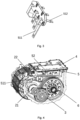
Fig. 4 shows a schematic drawing of an electric drive assembly system according to another embodiment of the present disclosure. -
Fig. 5 shows a top view of the electric drive assembly system inFig. 4 . -
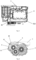
Fig. 6 shows a schematic drawing of an electric drive assembly system according to another embodiment of the present disclosure. -
Fig. 7 shows an oblique view of the housing of the electric drive assembly system inFig. 6 ; and -
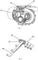
Fig. 8 shows a schematic drawing of an electrical connection assembly of an electric drive assembly system according to another embodiment of the present disclosure. - In order to clarify the technical solution objective, the technical solution and advantages of the present disclosure, the technical solution of embodiments of the present disclosure is described clearly and completely below in conjunction with the drawings accompanying particular embodiments of the present disclosure. In the drawings, identical reference numerals denote identical components. It must be explained that the embodiments described are some, not all, of the embodiments of the present disclosure. All other embodiments obtained by those skilled in the art based on the described embodiments of the present disclosure without the need for inventive effort shall fall within the scope of protection of the present disclosure.
- Unless otherwise defined, the technical or scientific terms used herein shall have the common meanings understood by those skilled in the art. "First", "second" and similar words used in the description and claims of the patent application of the present disclosure do not indicate any order, quantity or importance, being merely used to distinguish between different component parts. Likewise, words such as "a" or "one" do not necessarily represent a quantity limit. Words such as "comprising", "including" or "having" mean that the element or object preceding the word covers the elements or objects and equivalents thereof listed after the word, without excluding other elements or objects. Words such as "connection" or "communication", rather than being limited to the physical or mechanical connection or communication shown in a drawing, may include connection or communication equivalent thereto, irrespective of whether it is direct or indirect. "Upper", "lower", "left", "right", etc. are only used to indicate a relative positional relationship, and when the absolute position of the described object changes, the relative positional relationship might also change accordingly.
- Preferred embodiments of an electric drive assembly system for a vehicle according to the present disclosure are described in detail below with reference to
Figs. 1 - 8 .Figs. 1-3 show an electric drive assembly system contained in a vehicle, and an electrical connection assembly thereof, according to an embodiment of the present disclosure.Figs. 4-5 show an electric drive assembly system contained in a vehicle according to another embodiment of the present disclosure.Figs. 6-7 show an electric drive assembly system contained in a vehicle, and an electrical connection assembly thereof, according to another embodiment of the present disclosure.Fig. 8 shows an electrical connection assembly of an electric drive assembly system contained in a vehicle according to another embodiment of the present disclosure. The differences between these embodiments are mainly differences in electric machine control modules and/or electrical connection assemblies. - As shown in
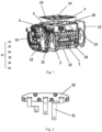
Fig. 1 , the electric drive assembly system of the present disclosure comprises ahousing 1, thehousing 1 comprising amain body 11 and a cover. In addition, the electric drive assembly system comprises anelectric machine 2, agearbox assembly 3, an electricmachine control module 4 and anelectrical connection assembly 5, all of which are disposed in thehousing 1. The electricmachine control module 4 may for example be an inverter, which converts DC power to AC power of fixed frequency and fixed voltage or adjustable frequency and adjustable voltage, for input to theelectric machine 2. Theelectric machine 2 is for example a permanent magnet synchronous electric machine or an AC asynchronous electric machine. Theelectric machine 2 is drive-connected to thegearbox assembly 3, to output the torque of theelectric machine 2 after speed reduction in thegearbox assembly 3. The electric machine control module inFig. 1 is located in the housing and therefore not visible; thereference numeral 4 merely indicates its position schematically. For the actual electric machine control module, seeFig. 4 . By installing apparatuses such as theelectric machine 2, thegearbox assembly 3 and the electricmachine control module 4 in one housing, a highly integrated design of the electric drive assembly system can be achieved, thereby saving space. - Specifically, the
electric machine 2 has a rotor shaft (not shown in the figure). Theelectric machine 2 may comprise a rotor and astator 22. The part of the electric machine that is fixed and immovable is called the stator, while the part capable of rotating is the rotor. For example, the stator is formed of a core, a winding and a base; the core is generally formed of stacked silicon steel plates. The rotor is mounted and fixed on the base by means of a bearing or bushing, and comprises the rotor shaft and a rotor core mounted on the rotor shaft. The electricmachine control module 4 is connected to wiring terminals of the stator so as to input AC power to the stator, thereby generating a rotating magnetic field. The rotor is cut by magnetic force lines in the rotating magnetic field, and thus generates an output current. In addition, the wheels of the vehicle can drive the rotor in reverse, inducing a rotating magnetic field in the other direction, to deliver electric power back to the battery via the electricmachine control module 4, which is an inverter. - The
gearbox assembly 3 has agear input shaft 21, thegear input shaft 21 being connected to the rotor shaft and disposed coaxially therewith, to receive torque from the electric machine. For example, thegear input shaft 21 may be rotatably fixed to the rotor shaft of the electric machine. It should be understood that the rotor shaft and gear input shaft may be two different shafts rotatably connected by a connecting element (e.g. connected by splines), or may be the same shaft; no restriction is imposed here. - The
gearbox assembly 3 may further comprise an intermediate shaft gearmeshed with thegear input shaft 21, and a differential assembly (such as the differential 6 shown inFig. 6 ), which can output the torque generated by theelectric machine 2 after speed reduction. The configuration of thegearbox assembly 3 is a common approach in the art, so is not described in detail in the present disclosure. - The electric
machine control module 4 is configured to control theelectric machine 2. The electricmachine control module 4 may comprise various electronic control elements and electrical control elements, and for example takes the form of a circuit board. Through control of an insulated-gate bipolar transistor (IGBT) integrated power module by the electronic control elements and electrical control elements, the electricmachine control module 4 can output a controllable threephase sine AC current, thereby controlling the rotation speed and torque of the electric machine. The electricmachine control module 4 is common in the art, so is not described in detail in the present disclosure. - In addition, the electric
machine control module 4 is superposed with theelectric machine 2 and/or thegearbox assembly 3 in a direction transverse to thegear input shaft 21. For example, the electricmachine control module 4 inFig. 1 is superposed with theelectric machine 2 in a vertical direction perpendicular to thegear input shaft 21; in simple terms, the electricmachine control module 4 and theelectric machine 2 may be described as being superposed. In other examples, e.g. as shown inFigs. 4 and6 - 7 , the electricmachine control module 4 is superposed with thegearbox assembly 3 in the vertical direction perpendicular to thegear input shaft 21; in simple terms, the electricmachine control module 4 and thegearbox assembly 3 may be described as being superposed. It may also be said that the electricmachine control module 4 inFigs. 4 and6 - 7 is superposed with theelectric machine 2 in a direction transverse to thegear input shaft 21 and inclined relative to the vertical direction in the figures. The specific position where the electricmachine control module 4 is disposed depends on the arrangement of the electronic components of the electricmachine control module 4, the form of thehousing 1, or the configuration of theelectric machine 2 and thegearbox assembly 3. - As shown in
Fig. 1 , the cover comprises agearbox cover 12, anelectric machine cover 13, and acontrol module cover 14. As shown inFig. 2 , thecontrol module cover 14 may be located at the top of themain body 11, with thegearbox cover 12 and theelectric machine cover 13 located at two ends of themain body 11, i.e. at a drive end and a non-drive end of the electric machine rotor shaft. Thegearbox assembly 3 is disposed in a first accommodating space formed by themain body 11 and thegearbox cover 12. The electricmachine control module 4 is disposed in a second accommodating space formed by themain body 11 and thecontrol module cover 14. Theelectric machine 2 is disposed in a third accommodating space formed by themain body 11 and theelectric machine cover 13. Specifically, themain body 11 of the housing comprises abase part 19 and multiple walls extending away from the base part towards atop edge 23 thereof, e.g. asidewall 10 protruding from the drive end of the rotor shaft, afirst wall 20, asecond wall 24 and athird wall 25. Thesidewall 10,first wall 20,second wall 24 andthird wall 25 may for example be walls extending perpendicular to thebase part 19. Thethird wall 25 is located close to the non-drive end of the electric machine rotor shaft. Thefirst wall 20 andsecond wall 24 extend between thesidewall 10 and thethird wall 25. In addition, as described above, themain body 11 further comprises a top wall (not shown in the figures), on which the electricmachine control module 4 is mounted. Thesidewall 10 may be bent close to thetop edge 23, so as to define the first accommodating space together with thegearbox cover 12. The top wall may be depressed relative to thetop edge 23, so as to define the second accommodating space together with thecontrol module cover 14. Thesecond wall 24 together with the top wall, thesidewall 10 and theelectric machine cover 13 define the third accommodating space. In other examples, thesecond wall 24 for example partially takes the form of a cylinder. - The
electrical connection assembly 5 is configured to electrically connect the electricmachine control module 4 to thestator 22 of theelectric machine 2, more precisely, to the wiring terminals of thestator 22. Theelectrical connection assembly 5 is configured to be electrically connected to thestator 22 of theelectric machine 2 close to thegear input shaft 21; for the position of thestator 22, seeFig. 4 . In other words, theelectrical connection assembly 5 is configured to be electrically connected to thestator 22 close to the drive end of the rotor shaft of the electric machine. As shown inFigs. 1 ,4 and6 , themain body 11 of thehousing 1 is provided with an opening in thesidewall 10 protruding from the drive end of the rotor shaft, and theelectrical connection assembly 5 passes through the opening, e.g. theopening 15 shown inFig. 7 . For example, the opening is located close to the drive end of the rotor shaft of the electric machine, in an unoccupied region of thesidewall 10 above thegear input shaft 21 or the differential 6. Thus, the electric drive assembly system of the present disclosure can utilize more effectively the space at the drive end of the rotor shaft of the electric machine which is not occupied by the gearbox assembly or the differential, thus realizing a design with a higher degree of integration. - As a result of having the
electrical connection assembly 5 disposed close to the drive end of the electric machine rotor shaft of the electric drive assembly system, the non-drive end thereof is expandable; that is to say, themain body 11 of thehousing 1 is extendable in the direction towards theelectric machine cover 13, i.e. the length of the stator or electric machine accommodated therein can be altered, without any need to redesign the electric machine control module and the electrical connection assembly. Thus, the electric drive assembly system of the present disclosure has application flexibility and a low cost. In addition, cooling oil stored in thegearbox assembly 3 can splash onto and cool afirst portion 511 of theelectrical connection assembly 5, the first portion being located in the first accommodating space that accommodates the gearbox assembly. Thus, the electric drive assembly system of the present disclosure has higher cooling efficiency. - As shown in
Fig. 2 , theelectrical connection assembly 5 comprises multiple busbars 51 (e.g. copper busbars) and an injection-mouldedmember 52. The number ofbusbars 51 may be three, used for three phases of current respectively. The injection-mouldedmember 52 is disposed on thebusbars 51 and closes theopening 15, seeFig. 7 . For example, the injection-mouldedmember 52 may be formed on themultiple busbars 51 by injection moulding. In addition, to seal the second accommodating space accommodating the electricmachine control module 4 relative to the first accommodating space accommodating thegearbox assembly 3, theelectrical connection assembly 5 may further comprise a sealing member (not shown inFig. 2 ), the sealing member being disposed between the injection-mouldedmember 52 and thesidewall 10 of thehousing 1. As shown inFig. 7 , the sealing member may be installed in agroove 16 around theopening 15. In other examples, the sealing member may be installed in a groove on the side of the injection-mouldedmember 52 that faces the opening, e.g. the sealingmember 53 shown inFig. 8 . For example, the sealingmember 53 may be formed integrally with thebusbars 51 and the injection-mouldedmember 52, or may be a separate component. In addition, as shown inFigs. 1 ,4 and6 , the injection-mouldedmember 52 is fitted to the opening from the outside of themain body 11. For example, theelectrical connection assembly 5 is fixed to themain body 11 by means of a connecting member. For example, theelectrical connection assembly 5 is fixed to thesidewall 10 by means of a screw or bolt passing through a mounting hole in the injection-mouldedmember 52. Of course, the present disclosure may also use other methods, such as bonding, riveting, welding, etc. - The electric
machine control module 4 comprises multiple output ends 41 corresponding to themultiple busbars 51, as shown inFig. 5 . In some examples, the multiple output ends 41 are arranged in a direction parallel to the direction of extension of thegear input shaft 21. In other examples, the multiple output ends 41 are arranged in a direction perpendicular to the direction of extension of thegear input shaft 21, e.g. the embodiments inFigs. 1 ,4 and5 . As shown inFig. 5 , the arrangement direction of the multiple output ends 41 is the horizontal extension direction in the figure, which is perpendicular to thegear input shaft 21 oriented in the vertical direction. - Specifically, the
busbars 51 pass through the opening, and comprisefirst portions 511 connected to thestator 22 andsecond portions 512 connected to the electricmachine control module 4, as shown inFigs. 3 and8 . Thefirst portions 511 are located in the first accommodating space defined by thegearbox cover 12 and themain body 11 of thehousing 1, and at least partially extend transversely with respect to thegear input shaft 21. Here, "transversely with respect to" includes perpendicular to thegear input shaft 21, and obliquely at an angle to thegear input shaft 21. In addition, as shown inFig. 6 , themain body 11 is provided with anotheropening 18 in thesidewall 10 protruding from the drive end of the rotor shaft, and thefirst portions 511 are electrically connected to the wiring terminals of the stator which are exposed through thisother opening 18. Thesecond portions 512 are located in the second accommodating space defined by thecontrol module cover 14 and themain body 11 of thehousing 1. As shown inFigs. 3, 4 and8 , thefirst portions 511 have a bent form, and thesecond portions 512 extend parallel to the direction of extension of thegear input shaft 21. As shown inFig. 3 , one part of eachfirst portion 511 extends perpendicular to thegear input shaft 21, another portion extends parallel to thegear input shaft 21, and thesecond portions 512 have the same length. As shown inFigs. 4 and5 , multiple parts of thefirst portions 511 extend transversely to the direction of extension of thegear input shaft 21, and thesecond portions 512 have the same length. As shown inFigs. 6 and8 , thefirst portions 511 have a bent form, and thesecond portions 512 extend parallel to the direction of extension of thegear input shaft 21 and have different lengths. In some examples, thefirst portions 511 are arranged side by side in the width direction thereof; as shown inFigs. 2 and3 , the threefirst portions 511 may be spaced apart by a large distance. In other examples, thefirst portions 511 are at least partially arranged side by side in the thickness direction thereof. Referring toFig. 8 , parts of the threefirst portions 511 are arranged side by side in the thickness direction thereof, and are thus overlapping. Of course, the multiplefirst portions 511 may also be arranged side by side in the thickness direction in their entirety, such that when observed in the thickness direction of thefirst portions 511, only onefirst portion 511 is visible. Thesecond portions 512 may be arranged in a similar manner to thefirst portions 511. As shown inFig. 3 , thesecond portions 512 are arranged side by side in the width direction thereof. As shown inFig. 8 , thesecond portions 512 are at least partially arranged side by side in the thickness direction thereof, and are thus overlapping, such that when observed in the thickness direction of thesecond portions 512, only onesecond portion 512 is visible. Compared with the electrical connection assembly inFig. 3 , the injection-moulded member of the electrical connection assembly shown inFig. 8 has a smaller size, while the required sealing area can be reduced, making it possible to achieve a better sealing result and more effective utilization of space, with a higher degree of integration. In addition, in some examples, themultiple busbars 51 pass through the same opening in thesidewall 10. In other examples, themultiple busbars 51 pass through multiple openings in thesidewall 10, the number of openings corresponding to the number of busbars. The different designs described above in relation to the busbars depend on the configuration of the housing, the gearbox assembly and the electric machine, and it may be said that the design of the busbars depends on the remaining space at the drive end that is not occupied by the gearbox assembly and the electric machine. In this way, the electric drive assembly system of the present disclosure can utilize space at the gearbox assembly more effectively, thus realizing a design with a higher degree of integration. - The left drive shaft and right drive shaft of the vehicle are connected to the differential in the gearbox assembly, and the differential is for example offset from the centre of the vehicle. In the vehicle of the present disclosure, the electric drive assembly system described above enables a reduction in the total length of the electric machine because the electrical connection assembly between the electric machine control module and the electric machine is installed at the drive end of the electric machine rotor shaft, and it is thus possible to have the electric drive assembly system disposed closer to the centre of the vehicle, thereby reducing the difference in length between the left drive shaft and the right drive shaft. This can also reduce the probability that an additional shaft for balancing the difference in length between the left drive shaft and the right drive shaft will be used, or avoid the use of such an additional shaft.
- The method for assembling an electric drive assembly system according to the present disclosure comprises the following steps: installing the
electric machine 2 in thehousing 1 of the electric drive assembly system; at the drive end of the rotor shaft of theelectric machine 2, inserting theelectrical connection assembly 5 from outside themain body 11 of thehousing 1 into an opening provided in thesidewall 10 of themain body 11; connecting theelectrical connection assembly 5 to thestator 22 of the electric machine 2 (more precisely, to the wiring terminals of the stator 22); installing thegearbox assembly 3 and the electricmachine control module 4 in thehousing 1 of the electric drive assembly system; and connecting theelectrical connection assembly 5 to the electricmachine control module 4. The electric drive assembly system described above may be assembled according to the assembly method. For example, the step of inserting the abovementionedelectrical connection assembly 5 may specifically be performed in a direction parallel to thegear input shaft 21. - The technical features disclosed above are not limited to the disclosed combinations with other features, and those skilled in the art could make other combinations of technical features according to the objective of the invention, to achieve the objective of the present disclosure.
Claims (14)
- An electric drive assembly system, characterized in that the electric drive assembly system comprises:a housing (1), comprising a main body (11) and a cover; andthe following, disposed in the housing (1):an electric machine (2), comprising a rotor shaft;a gearbox assembly (3), comprising a gear input shaft (21) connected to the rotor shaft and disposed coaxially therewith, to receive torque from the electric machine;an electric machine control module (4), configured to control the electric machine (2), and superposed with the electric machine (2) and/or the gearbox assembly (3) in a direction transverse to the gear input shaft (21); andan electrical connection assembly (5), configured to electrically connect the electric machine control module (4) to a stator (22) of the electric machine (2),wherein the electrical connection assembly (5) is configured to be electrically connected to the stator (22) of the electric machine (2) close to a drive end of the rotor shaft of the electric machine, andwherein the main body (11) of the housing (1) is provided with at least one opening in a sidewall (10) protruding from the drive end of the rotor shaft, and the electrical connection assembly (5) passes through the opening.
- The electric drive assembly system according to Claim 1, characterized in that the electrical connection assembly (5) comprises multiple busbars (51), an injection-moulded member (52) and a sealing member (53), the injection-moulded member (52) being disposed on the busbars (51) and closing the opening, and the sealing member (53) being disposed between the injection-moulded member and the sidewall (10).
- The electric drive assembly system according to Claim 2, characterized in that the injection-moulded member (52) is formed on the multiple busbars (51) by injection-moulding.
- The electric drive assembly system according to Claim 2, characterized in that the busbars (51) pass through the opening, and comprise first portions (511) connected to the stator (22) and second portions (512) connected to the electric machine control module (4).
- The electric drive assembly system according to Claim 4, characterized in that the cover comprises a gearbox cover (12), an electric machine cover (13) and a control module cover (14),
wherein the first portions (511) are located in a first accommodating space defined by the gearbox cover (12) and the main body (11) of the housing (1) and at least partially extend transversely with respect to the gear input shaft (21), and the second portions (512) are located in a second accommodating space defined by the control module cover (14) and the main body (11) of the housing (1). - The electric drive assembly system according to Claim 2, characterized in that the electrical connection assembly (5) is fixed to the main body (11) by means of a connecting member.
- The electric drive assembly system according to Claim 4, characterized in that the electric machine control module (4) comprises multiple output ends (41) corresponding to the multiple busbars (51), the multiple output ends (41) being arranged in a direction parallel to the direction of extension of the gear input shaft (21).
- The electric drive assembly system according to Claim 4, characterized in that the electric machine control module (4) comprises multiple output ends (41) corresponding to the multiple busbars (51), the multiple output ends (41) being arranged in a direction perpendicular to the direction of extension of the gear input shaft (21).
- The electric drive assembly system according to Claim 7 or 8, characterized in that the second portions (512) extend parallel to the direction of extension of the gear input shaft (21).
- The electric drive assembly system according to Claim 7 or 8, characterized in that the first portions (511) and/or the second portions (512) are arranged side by side in their respective width directions, or at least partially arranged side by side in their respective thickness directions.
- The electric drive assembly system according to Claim 10, characterized in that the multiple busbars (51) pass through the same opening or multiple corresponding openings in the sidewall (10).
- A vehicle, characterized in that the vehicle comprises the electric drive assembly system according to any one of Claims 1 to 11.
- A method for assembling an electric drive assembly system, characterized in that the assembly method comprises:installing an electric machine (2) in a housing (1) of the electric drive assembly system;at a drive end of a rotor shaft of the electric machine (2), inserting an electrical connection assembly (5) from outside a main body (11) of the housing (1) into an opening provided in a sidewall (10) of the main body (11);connecting the electrical connection assembly (5) to a stator (22) of the electric machine (2);installing a gearbox assembly (3) and an electric machine control module (4) in the housing (1); andconnecting the electrical connection assembly (5) to the electric machine control module (4).
- An assembly method according to Claim 13, characterized in that the electric drive assembly system is configured according to any one of Claims 1 to 11.
Applications Claiming Priority (1)
| Application Number | Priority Date | Filing Date | Title |
|---|---|---|---|
| CN202210698418.9A CN117318400A (en) | 2022-06-20 | 2022-06-20 | Electric drive assembly, vehicle and method for assembling an electric drive assembly |
Publications (1)
| Publication Number | Publication Date |
|---|---|
| EP4297253A1 true EP4297253A1 (en) | 2023-12-27 |
Family
ID=86899178
Family Applications (1)
| Application Number | Title | Priority Date | Filing Date |
|---|---|---|---|
| EP23180114.3A Pending EP4297253A1 (en) | 2022-06-20 | 2023-06-19 | Electric drive assembly system, vehicle and method for assembling electric drive assembly system |
Country Status (5)
| Country | Link |
|---|---|
| US (1) | US20230412039A1 (en) |
| EP (1) | EP4297253A1 (en) |
| JP (1) | JP2024000539A (en) |
| KR (1) | KR20230174183A (en) |
| CN (1) | CN117318400A (en) |
Citations (4)
| Publication number | Priority date | Publication date | Assignee | Title |
|---|---|---|---|---|
| US20200266680A1 (en) * | 2019-02-15 | 2020-08-20 | Nidec Corporation | Motor unit |
| WO2021044809A1 (en) * | 2019-09-03 | 2021-03-11 | 日立オートモティブシステムズ株式会社 | Electrical system |
| CN112840535A (en) * | 2018-09-28 | 2021-05-25 | 日本电产株式会社 | Motor unit |
| WO2021166299A1 (en) * | 2020-02-19 | 2021-08-26 | 日本電産株式会社 | Motor unit |
-
2022
- 2022-06-20 CN CN202210698418.9A patent/CN117318400A/en active Pending
-
2023
- 2023-06-19 KR KR1020230078384A patent/KR20230174183A/en unknown
- 2023-06-19 JP JP2023100311A patent/JP2024000539A/en active Pending
- 2023-06-19 EP EP23180114.3A patent/EP4297253A1/en active Pending
- 2023-06-20 US US18/337,845 patent/US20230412039A1/en active Pending
Patent Citations (4)
| Publication number | Priority date | Publication date | Assignee | Title |
|---|---|---|---|---|
| CN112840535A (en) * | 2018-09-28 | 2021-05-25 | 日本电产株式会社 | Motor unit |
| US20200266680A1 (en) * | 2019-02-15 | 2020-08-20 | Nidec Corporation | Motor unit |
| WO2021044809A1 (en) * | 2019-09-03 | 2021-03-11 | 日立オートモティブシステムズ株式会社 | Electrical system |
| WO2021166299A1 (en) * | 2020-02-19 | 2021-08-26 | 日本電産株式会社 | Motor unit |
Also Published As
| Publication number | Publication date |
|---|---|
| CN117318400A (en) | 2023-12-29 |
| KR20230174183A (en) | 2023-12-27 |
| US20230412039A1 (en) | 2023-12-21 |
| JP2024000539A (en) | 2024-01-05 |
Similar Documents
| Publication | Publication Date | Title |
|---|---|---|
| EP2571147B1 (en) | Electric driving device and electric power steering device equipped with same | |
| US8924081B2 (en) | Electric power steering apparatus and control device integrated-type electric motor | |
| US9425707B2 (en) | Inverter device capable of appropriately fixing a power module having a switching element and a smoothing capacitor in a limited region | |
| US9543802B2 (en) | Motor drive apparatus | |
| EP2194634B1 (en) | Electric compressor for on-vehicle air conditioner | |
| US20140239755A1 (en) | Rotating electrical machine | |
| CN106797162B (en) | axially extending motor electronics cooling tower | |
| EP2840686B1 (en) | Electric rotating machine | |
| US20200169147A1 (en) | Motor vehicle and power converter device for a motor vehicle | |
| US20140239750A1 (en) | Rotating electrical machine | |
| CN110168683B (en) | Capacitor component for an electric motor or generator | |
| CN107852071B (en) | Rotating electrical machine | |
| US20140239758A1 (en) | Rotating electrical machine | |
| CN113661640A (en) | Motor unit | |
| JP2015006118A (en) | Rotary electric machine for vehicle | |
| JP7512861B2 (en) | Drive unit | |
| US20240258894A1 (en) | Rotary electric machine | |
| CN111971880B (en) | Electric power steering device | |
| EP4297253A1 (en) | Electric drive assembly system, vehicle and method for assembling electric drive assembly system | |
| US11509187B2 (en) | Integrated terminal box of a rotary dynamoelectric machine | |
| US20230412038A1 (en) | Electric drive assembly system, vehicle and assembly method of electric drive assembly system | |
| US20240258861A1 (en) | Rotary electric machine | |
| US20240258885A1 (en) | Rotary electric machine | |
| WO2024038500A1 (en) | Electric drive apparatus | |
| EP4245584A1 (en) | Vehicular drive device |
Legal Events
| Date | Code | Title | Description |
|---|---|---|---|
| PUAI | Public reference made under article 153(3) epc to a published international application that has entered the european phase |
Free format text: ORIGINAL CODE: 0009012 |
|
| STAA | Information on the status of an ep patent application or granted ep patent |
Free format text: STATUS: THE APPLICATION HAS BEEN PUBLISHED |
|
| AK | Designated contracting states |
Kind code of ref document: A1 Designated state(s): AL AT BE BG CH CY CZ DE DK EE ES FI FR GB GR HR HU IE IS IT LI LT LU LV MC ME MK MT NL NO PL PT RO RS SE SI SK SM TR |
|
| STAA | Information on the status of an ep patent application or granted ep patent |
Free format text: STATUS: REQUEST FOR EXAMINATION WAS MADE |
|
| 17P | Request for examination filed |
Effective date: 20240627 |
|
| RBV | Designated contracting states (corrected) |
Designated state(s): AL AT BE BG CH CY CZ DE DK EE ES FI FR GB GR HR HU IE IS IT LI LT LU LV MC ME MK MT NL NO PL PT RO RS SE SI SK SM TR |