EP4297253A1 - Système d'ensemble d'entraînement électrique, véhicule et procédé d'assemblage de système d'ensemble d'entraînement électrique - Google Patents
Système d'ensemble d'entraînement électrique, véhicule et procédé d'assemblage de système d'ensemble d'entraînement électrique Download PDFInfo
- Publication number
- EP4297253A1 EP4297253A1 EP23180114.3A EP23180114A EP4297253A1 EP 4297253 A1 EP4297253 A1 EP 4297253A1 EP 23180114 A EP23180114 A EP 23180114A EP 4297253 A1 EP4297253 A1 EP 4297253A1
- Authority
- EP
- European Patent Office
- Prior art keywords
- electric machine
- drive assembly
- assembly system
- electric drive
- control module
- Prior art date
- Legal status (The legal status is an assumption and is not a legal conclusion. Google has not performed a legal analysis and makes no representation as to the accuracy of the status listed.)
- Pending
Links
Images
Classifications
-
- H—ELECTRICITY
- H02—GENERATION; CONVERSION OR DISTRIBUTION OF ELECTRIC POWER
- H02K—DYNAMO-ELECTRIC MACHINES
- H02K5/00—Casings; Enclosures; Supports
- H02K5/04—Casings or enclosures characterised by the shape, form or construction thereof
- H02K5/22—Auxiliary parts of casings not covered by groups H02K5/06-H02K5/20, e.g. shaped to form connection boxes or terminal boxes
- H02K5/225—Terminal boxes or connection arrangements
-
- H—ELECTRICITY
- H02—GENERATION; CONVERSION OR DISTRIBUTION OF ELECTRIC POWER
- H02K—DYNAMO-ELECTRIC MACHINES
- H02K7/00—Arrangements for handling mechanical energy structurally associated with dynamo-electric machines, e.g. structural association with mechanical driving motors or auxiliary dynamo-electric machines
- H02K7/10—Structural association with clutches, brakes, gears, pulleys or mechanical starters
- H02K7/116—Structural association with clutches, brakes, gears, pulleys or mechanical starters with gears
-
- B—PERFORMING OPERATIONS; TRANSPORTING
- B60—VEHICLES IN GENERAL
- B60K—ARRANGEMENT OR MOUNTING OF PROPULSION UNITS OR OF TRANSMISSIONS IN VEHICLES; ARRANGEMENT OR MOUNTING OF PLURAL DIVERSE PRIME-MOVERS IN VEHICLES; AUXILIARY DRIVES FOR VEHICLES; INSTRUMENTATION OR DASHBOARDS FOR VEHICLES; ARRANGEMENTS IN CONNECTION WITH COOLING, AIR INTAKE, GAS EXHAUST OR FUEL SUPPLY OF PROPULSION UNITS IN VEHICLES
- B60K1/00—Arrangement or mounting of electrical propulsion units
-
- B—PERFORMING OPERATIONS; TRANSPORTING
- B60—VEHICLES IN GENERAL
- B60K—ARRANGEMENT OR MOUNTING OF PROPULSION UNITS OR OF TRANSMISSIONS IN VEHICLES; ARRANGEMENT OR MOUNTING OF PLURAL DIVERSE PRIME-MOVERS IN VEHICLES; AUXILIARY DRIVES FOR VEHICLES; INSTRUMENTATION OR DASHBOARDS FOR VEHICLES; ARRANGEMENTS IN CONNECTION WITH COOLING, AIR INTAKE, GAS EXHAUST OR FUEL SUPPLY OF PROPULSION UNITS IN VEHICLES
- B60K17/00—Arrangement or mounting of transmissions in vehicles
- B60K17/04—Arrangement or mounting of transmissions in vehicles characterised by arrangement, location or kind of gearing
- B60K17/06—Arrangement or mounting of transmissions in vehicles characterised by arrangement, location or kind of gearing of change-speed gearing
-
- B—PERFORMING OPERATIONS; TRANSPORTING
- B60—VEHICLES IN GENERAL
- B60L—PROPULSION OF ELECTRICALLY-PROPELLED VEHICLES; SUPPLYING ELECTRIC POWER FOR AUXILIARY EQUIPMENT OF ELECTRICALLY-PROPELLED VEHICLES; ELECTRODYNAMIC BRAKE SYSTEMS FOR VEHICLES IN GENERAL; MAGNETIC SUSPENSION OR LEVITATION FOR VEHICLES; MONITORING OPERATING VARIABLES OF ELECTRICALLY-PROPELLED VEHICLES; ELECTRIC SAFETY DEVICES FOR ELECTRICALLY-PROPELLED VEHICLES
- B60L15/00—Methods, circuits, or devices for controlling the traction-motor speed of electrically-propelled vehicles
- B60L15/007—Physical arrangements or structures of drive train converters specially adapted for the propulsion motors of electric vehicles
-
- B—PERFORMING OPERATIONS; TRANSPORTING
- B60—VEHICLES IN GENERAL
- B60L—PROPULSION OF ELECTRICALLY-PROPELLED VEHICLES; SUPPLYING ELECTRIC POWER FOR AUXILIARY EQUIPMENT OF ELECTRICALLY-PROPELLED VEHICLES; ELECTRODYNAMIC BRAKE SYSTEMS FOR VEHICLES IN GENERAL; MAGNETIC SUSPENSION OR LEVITATION FOR VEHICLES; MONITORING OPERATING VARIABLES OF ELECTRICALLY-PROPELLED VEHICLES; ELECTRIC SAFETY DEVICES FOR ELECTRICALLY-PROPELLED VEHICLES
- B60L50/00—Electric propulsion with power supplied within the vehicle
- B60L50/50—Electric propulsion with power supplied within the vehicle using propulsion power supplied by batteries or fuel cells
- B60L50/51—Electric propulsion with power supplied within the vehicle using propulsion power supplied by batteries or fuel cells characterised by AC-motors
-
- B—PERFORMING OPERATIONS; TRANSPORTING
- B60—VEHICLES IN GENERAL
- B60R—VEHICLES, VEHICLE FITTINGS, OR VEHICLE PARTS, NOT OTHERWISE PROVIDED FOR
- B60R16/00—Electric or fluid circuits specially adapted for vehicles and not otherwise provided for; Arrangement of elements of electric or fluid circuits specially adapted for vehicles and not otherwise provided for
- B60R16/02—Electric or fluid circuits specially adapted for vehicles and not otherwise provided for; Arrangement of elements of electric or fluid circuits specially adapted for vehicles and not otherwise provided for electric constitutive elements
-
- H—ELECTRICITY
- H02—GENERATION; CONVERSION OR DISTRIBUTION OF ELECTRIC POWER
- H02K—DYNAMO-ELECTRIC MACHINES
- H02K11/00—Structural association of dynamo-electric machines with electric components or with devices for shielding, monitoring or protection
- H02K11/0094—Structural association with other electrical or electronic devices
-
- H—ELECTRICITY
- H02—GENERATION; CONVERSION OR DISTRIBUTION OF ELECTRIC POWER
- H02K—DYNAMO-ELECTRIC MACHINES
- H02K11/00—Structural association of dynamo-electric machines with electric components or with devices for shielding, monitoring or protection
- H02K11/30—Structural association with control circuits or drive circuits
- H02K11/33—Drive circuits, e.g. power electronics
-
- H—ELECTRICITY
- H02—GENERATION; CONVERSION OR DISTRIBUTION OF ELECTRIC POWER
- H02K—DYNAMO-ELECTRIC MACHINES
- H02K15/00—Processes or apparatus specially adapted for manufacturing, assembling, maintaining or repairing of dynamo-electric machines
-
- H—ELECTRICITY
- H02—GENERATION; CONVERSION OR DISTRIBUTION OF ELECTRIC POWER
- H02K—DYNAMO-ELECTRIC MACHINES
- H02K15/00—Processes or apparatus specially adapted for manufacturing, assembling, maintaining or repairing of dynamo-electric machines
- H02K15/14—Casings; Enclosures; Supports
-
- H—ELECTRICITY
- H02—GENERATION; CONVERSION OR DISTRIBUTION OF ELECTRIC POWER
- H02K—DYNAMO-ELECTRIC MACHINES
- H02K17/00—Asynchronous induction motors; Asynchronous induction generators
- H02K17/02—Asynchronous induction motors
- H02K17/30—Structural association of asynchronous induction motors with auxiliary electric devices influencing the characteristics of the motor or controlling the motor, e.g. with impedances or switches
-
- H—ELECTRICITY
- H02—GENERATION; CONVERSION OR DISTRIBUTION OF ELECTRIC POWER
- H02K—DYNAMO-ELECTRIC MACHINES
- H02K3/00—Details of windings
- H02K3/46—Fastening of windings on the stator or rotor structure
- H02K3/50—Fastening of winding heads, equalising connectors, or connections thereto
-
- H—ELECTRICITY
- H02—GENERATION; CONVERSION OR DISTRIBUTION OF ELECTRIC POWER
- H02K—DYNAMO-ELECTRIC MACHINES
- H02K3/00—Details of windings
- H02K3/46—Fastening of windings on the stator or rotor structure
- H02K3/52—Fastening salient pole windings or connections thereto
-
- H—ELECTRICITY
- H02—GENERATION; CONVERSION OR DISTRIBUTION OF ELECTRIC POWER
- H02K—DYNAMO-ELECTRIC MACHINES
- H02K5/00—Casings; Enclosures; Supports
- H02K5/04—Casings or enclosures characterised by the shape, form or construction thereof
-
- H—ELECTRICITY
- H02—GENERATION; CONVERSION OR DISTRIBUTION OF ELECTRIC POWER
- H02K—DYNAMO-ELECTRIC MACHINES
- H02K7/00—Arrangements for handling mechanical energy structurally associated with dynamo-electric machines, e.g. structural association with mechanical driving motors or auxiliary dynamo-electric machines
- H02K7/006—Structural association of a motor or generator with the drive train of a motor vehicle
-
- H—ELECTRICITY
- H02—GENERATION; CONVERSION OR DISTRIBUTION OF ELECTRIC POWER
- H02K—DYNAMO-ELECTRIC MACHINES
- H02K9/00—Arrangements for cooling or ventilating
- H02K9/19—Arrangements for cooling or ventilating for machines with closed casing and closed-circuit cooling using a liquid cooling medium, e.g. oil
-
- H—ELECTRICITY
- H05—ELECTRIC TECHNIQUES NOT OTHERWISE PROVIDED FOR
- H05K—PRINTED CIRCUITS; CASINGS OR CONSTRUCTIONAL DETAILS OF ELECTRIC APPARATUS; MANUFACTURE OF ASSEMBLAGES OF ELECTRICAL COMPONENTS
- H05K7/00—Constructional details common to different types of electric apparatus
- H05K7/20—Modifications to facilitate cooling, ventilating, or heating
- H05K7/20218—Modifications to facilitate cooling, ventilating, or heating using a liquid coolant without phase change in electronic enclosures
-
- H—ELECTRICITY
- H02—GENERATION; CONVERSION OR DISTRIBUTION OF ELECTRIC POWER
- H02K—DYNAMO-ELECTRIC MACHINES
- H02K2203/00—Specific aspects not provided for in the other groups of this subclass relating to the windings
- H02K2203/09—Machines characterised by wiring elements other than wires, e.g. bus rings, for connecting the winding terminations
Definitions
- the present disclosure relates to the field of vehicles, in particular to an electric drive assembly system, a vehicle comprising the electric drive assembly system, and a method for assembling the electric drive assembly system.
- an electric drive assembly system comprising:
- the busbars pass through the opening, and comprise first portions connected to the stator and second portions connected to the electric machine control module.
- the cover comprises a gearbox cover, an electric machine cover and a control module cover, wherein the first portions are located in a first accommodating space defined by the gearbox cover and the main body of the housing and at least partially extend transversely with respect to the gear input shaft, and the second portions are located in a second accommodating space defined by the control module cover and the main body of the housing.
- the electric machine control module comprises multiple output ends corresponding to the multiple busbars, the multiple output ends being arranged in a direction perpendicular to the direction of extension of the gear input shaft.
- the second portions extend parallel to the direction of extension of the gear input shaft.
- first portions and/or the second portions are arranged side by side in their respective width directions, or at least partially arranged side by side in their respective thickness directions.
- the multiple busbars pass through the same opening or multiple corresponding openings in the sidewall.
- the present disclosure provides a vehicle, comprising the electric drive assembly system as described above.
- the present disclosure provides a method for assembling an electric drive assembly system, the assembly method comprising the following steps:
- the electric drive assembly system is configured as described above.
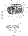
- FIG. 1 show an electric drive assembly system contained in a vehicle, and an electrical connection assembly thereof, according to an embodiment of the present disclosure.
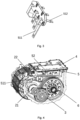
- Figs. 4-5 show an electric drive assembly system contained in a vehicle according to another embodiment of the present disclosure.
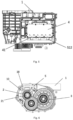
- Figs. 6-7 show an electric drive assembly system contained in a vehicle, and an electrical connection assembly thereof, according to another embodiment of the present disclosure.
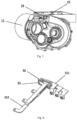
- Fig. 8 shows an electrical connection assembly of an electric drive assembly system contained in a vehicle according to another embodiment of the present disclosure.
- the differences between these embodiments are mainly differences in electric machine control modules and/or electrical connection assemblies.
- the electric drive assembly system of the present disclosure comprises a housing 1, the housing 1 comprising a main body 11 and a cover.
- the electric drive assembly system comprises an electric machine 2, a gearbox assembly 3, an electric machine control module 4 and an electrical connection assembly 5, all of which are disposed in the housing 1.
- the electric machine control module 4 may for example be an inverter, which converts DC power to AC power of fixed frequency and fixed voltage or adjustable frequency and adjustable voltage, for input to the electric machine 2.
- the electric machine 2 is for example a permanent magnet synchronous electric machine or an AC asynchronous electric machine.
- the electric machine 2 is drive-connected to the gearbox assembly 3, to output the torque of the electric machine 2 after speed reduction in the gearbox assembly 3.
- the rotor is cut by magnetic force lines in the rotating magnetic field, and thus generates an output current.
- the wheels of the vehicle can drive the rotor in reverse, inducing a rotating magnetic field in the other direction, to deliver electric power back to the battery via the electric machine control module 4, which is an inverter.
- the gearbox assembly 3 has a gear input shaft 21, the gear input shaft 21 being connected to the rotor shaft and disposed coaxially therewith, to receive torque from the electric machine.
- the gear input shaft 21 may be rotatably fixed to the rotor shaft of the electric machine.
- the rotor shaft and gear input shaft may be two different shafts rotatably connected by a connecting element (e.g. connected by splines), or may be the same shaft; no restriction is imposed here.
- the gearbox assembly 3 may further comprise an intermediate shaft gearmeshed with the gear input shaft 21, and a differential assembly (such as the differential 6 shown in Fig. 6 ), which can output the torque generated by the electric machine 2 after speed reduction.
- a differential assembly such as the differential 6 shown in Fig. 6
- the configuration of the gearbox assembly 3 is a common approach in the art, so is not described in detail in the present disclosure.
- the electric machine control module 4 is superposed with the electric machine 2 and/or the gearbox assembly 3 in a direction transverse to the gear input shaft 21.
- the electric machine control module 4 in Fig. 1 is superposed with the electric machine 2 in a vertical direction perpendicular to the gear input shaft 21; in simple terms, the electric machine control module 4 and the electric machine 2 may be described as being superposed.
- the electric machine control module 4 is superposed with the gearbox assembly 3 in the vertical direction perpendicular to the gear input shaft 21; in simple terms, the electric machine control module 4 and the gearbox assembly 3 may be described as being superposed.
- the electric machine control module 4 in Figs. 4 and 6 - 7 is superposed with the electric machine 2 in a direction transverse to the gear input shaft 21 and inclined relative to the vertical direction in the figures.
- the specific position where the electric machine control module 4 is disposed depends on the arrangement of the electronic components of the electric machine control module 4, the form of the housing 1, or the configuration of the electric machine 2 and the gearbox assembly 3.
- the cover comprises a gearbox cover 12, an electric machine cover 13, and a control module cover 14.
- the control module cover 14 may be located at the top of the main body 11, with the gearbox cover 12 and the electric machine cover 13 located at two ends of the main body 11, i.e. at a drive end and a non-drive end of the electric machine rotor shaft.
- the gearbox assembly 3 is disposed in a first accommodating space formed by the main body 11 and the gearbox cover 12.
- the electric machine control module 4 is disposed in a second accommodating space formed by the main body 11 and the control module cover 14.
- the electric machine 2 is disposed in a third accommodating space formed by the main body 11 and the electric machine cover 13.
- the sidewall 10 may be bent close to the top edge 23, so as to define the first accommodating space together with the gearbox cover 12.
- the top wall may be depressed relative to the top edge 23, so as to define the second accommodating space together with the control module cover 14.
- the second wall 24 together with the top wall, the sidewall 10 and the electric machine cover 13 define the third accommodating space.
- the second wall 24 for example partially takes the form of a cylinder.
- the electrical connection assembly 5 is configured to electrically connect the electric machine control module 4 to the stator 22 of the electric machine 2, more precisely, to the wiring terminals of the stator 22.
- the electrical connection assembly 5 is configured to be electrically connected to the stator 22 of the electric machine 2 close to the gear input shaft 21; for the position of the stator 22, see Fig. 4 .
- the electrical connection assembly 5 is configured to be electrically connected to the stator 22 close to the drive end of the rotor shaft of the electric machine.
- the main body 11 of the housing 1 is provided with an opening in the sidewall 10 protruding from the drive end of the rotor shaft, and the electrical connection assembly 5 passes through the opening, e.g.
- the electric drive assembly system of the present disclosure has application flexibility and a low cost.
- cooling oil stored in the gearbox assembly 3 can splash onto and cool a first portion 511 of the electrical connection assembly 5, the first portion being located in the first accommodating space that accommodates the gearbox assembly.
- the electric drive assembly system of the present disclosure has higher cooling efficiency.
- the sealing member being disposed between the injection-moulded member 52 and the sidewall 10 of the housing 1.
- the sealing member may be installed in a groove 16 around the opening 15.
- the sealing member may be installed in a groove on the side of the injection-moulded member 52 that faces the opening, e.g. the sealing member 53 shown in Fig. 8 .
- the sealing member 53 may be formed integrally with the busbars 51 and the injection-moulded member 52, or may be a separate component.
- the injection-moulded member 52 is fitted to the opening from the outside of the main body 11.
- first portions 511 extend transversely to the direction of extension of the gear input shaft 21, and the second portions 512 have the same length.
- the first portions 511 have a bent form, and the second portions 512 extend parallel to the direction of extension of the gear input shaft 21 and have different lengths.
- the first portions 511 are arranged side by side in the width direction thereof; as shown in Figs. 2 and 3 , the three first portions 511 may be spaced apart by a large distance.
- the first portions 511 are at least partially arranged side by side in the thickness direction thereof. Referring to Fig.
- busbars depend on the configuration of the housing, the gearbox assembly and the electric machine, and it may be said that the design of the busbars depends on the remaining space at the drive end that is not occupied by the gearbox assembly and the electric machine.
- the electric drive assembly system of the present disclosure can utilize space at the gearbox assembly more effectively, thus realizing a design with a higher degree of integration.
- the method for assembling an electric drive assembly system comprises the following steps: installing the electric machine 2 in the housing 1 of the electric drive assembly system; at the drive end of the rotor shaft of the electric machine 2, inserting the electrical connection assembly 5 from outside the main body 11 of the housing 1 into an opening provided in the sidewall 10 of the main body 11; connecting the electrical connection assembly 5 to the stator 22 of the electric machine 2 (more precisely, to the wiring terminals of the stator 22); installing the gearbox assembly 3 and the electric machine control module 4 in the housing 1 of the electric drive assembly system; and connecting the electrical connection assembly 5 to the electric machine control module 4.
- the electric drive assembly system described above may be assembled according to the assembly method.
- the step of inserting the abovementioned electrical connection assembly 5 may specifically be performed in a direction parallel to the gear input shaft 21.
Landscapes
- Engineering & Computer Science (AREA)
- Power Engineering (AREA)
- Mechanical Engineering (AREA)
- Transportation (AREA)
- Microelectronics & Electronic Packaging (AREA)
- Sustainable Energy (AREA)
- Life Sciences & Earth Sciences (AREA)
- Manufacturing & Machinery (AREA)
- Sustainable Development (AREA)
- Chemical & Material Sciences (AREA)
- Combustion & Propulsion (AREA)
- Physics & Mathematics (AREA)
- Thermal Sciences (AREA)
- Motor Or Generator Frames (AREA)
- Manufacture Of Motors, Generators (AREA)
Applications Claiming Priority (1)
| Application Number | Priority Date | Filing Date | Title |
|---|---|---|---|
| CN202210698418.9A CN117318400A (zh) | 2022-06-20 | 2022-06-20 | 电驱动总成系统、车辆以及电驱动总成系统的装配方法 |
Publications (1)
| Publication Number | Publication Date |
|---|---|
| EP4297253A1 true EP4297253A1 (fr) | 2023-12-27 |
Family
ID=86899178
Family Applications (1)
| Application Number | Title | Priority Date | Filing Date |
|---|---|---|---|
| EP23180114.3A Pending EP4297253A1 (fr) | 2022-06-20 | 2023-06-19 | Système d'ensemble d'entraînement électrique, véhicule et procédé d'assemblage de système d'ensemble d'entraînement électrique |
Country Status (5)
| Country | Link |
|---|---|
| US (1) | US20230412039A1 (fr) |
| EP (1) | EP4297253A1 (fr) |
| JP (1) | JP2024000539A (fr) |
| KR (1) | KR20230174183A (fr) |
| CN (1) | CN117318400A (fr) |
Families Citing this family (3)
| Publication number | Priority date | Publication date | Assignee | Title |
|---|---|---|---|---|
| CN117294083A (zh) * | 2022-06-20 | 2023-12-26 | 法雷奥西门子新能源汽车德国有限责任公司 | 电驱动总成系统、车辆以及电驱动总成系统的装配方法 |
| JP2026000649A (ja) * | 2024-06-18 | 2026-01-06 | マツダ株式会社 | 回転電機 |
| CN119567894B (zh) * | 2024-12-31 | 2025-11-14 | 华为技术有限公司 | 供电装置、动力总成及电动车 |
Citations (4)
| Publication number | Priority date | Publication date | Assignee | Title |
|---|---|---|---|---|
| US20200266680A1 (en) * | 2019-02-15 | 2020-08-20 | Nidec Corporation | Motor unit |
| WO2021044809A1 (fr) * | 2019-09-03 | 2021-03-11 | 日立オートモティブシステムズ株式会社 | Système électrique |
| CN112840535A (zh) * | 2018-09-28 | 2021-05-25 | 日本电产株式会社 | 马达单元 |
| WO2021166299A1 (fr) * | 2020-02-19 | 2021-08-26 | 日本電産株式会社 | Unité de moteur |
Family Cites Families (1)
| Publication number | Priority date | Publication date | Assignee | Title |
|---|---|---|---|---|
| DE112020001868T5 (de) * | 2019-04-11 | 2021-12-30 | Nidec Corporation | Motoreinheit |
-
2022
- 2022-06-20 CN CN202210698418.9A patent/CN117318400A/zh active Pending
-
2023
- 2023-06-19 JP JP2023100311A patent/JP2024000539A/ja active Pending
- 2023-06-19 EP EP23180114.3A patent/EP4297253A1/fr active Pending
- 2023-06-19 KR KR1020230078384A patent/KR20230174183A/ko active Pending
- 2023-06-20 US US18/337,845 patent/US20230412039A1/en active Pending
Patent Citations (4)
| Publication number | Priority date | Publication date | Assignee | Title |
|---|---|---|---|---|
| CN112840535A (zh) * | 2018-09-28 | 2021-05-25 | 日本电产株式会社 | 马达单元 |
| US20200266680A1 (en) * | 2019-02-15 | 2020-08-20 | Nidec Corporation | Motor unit |
| WO2021044809A1 (fr) * | 2019-09-03 | 2021-03-11 | 日立オートモティブシステムズ株式会社 | Système électrique |
| WO2021166299A1 (fr) * | 2020-02-19 | 2021-08-26 | 日本電産株式会社 | Unité de moteur |
Also Published As
| Publication number | Publication date |
|---|---|
| US20230412039A1 (en) | 2023-12-21 |
| JP2024000539A (ja) | 2024-01-05 |
| CN117318400A (zh) | 2023-12-29 |
| KR20230174183A (ko) | 2023-12-27 |
Similar Documents
| Publication | Publication Date | Title |
|---|---|---|
| EP4297253A1 (fr) | Système d'ensemble d'entraînement électrique, véhicule et procédé d'assemblage de système d'ensemble d'entraînement électrique | |
| EP2571147B1 (fr) | Dispositif d'entraînement électrique et dispositif de direction assistée électrique doté dudit dispositif | |
| US8924081B2 (en) | Electric power steering apparatus and control device integrated-type electric motor | |
| US9425707B2 (en) | Inverter device capable of appropriately fixing a power module having a switching element and a smoothing capacitor in a limited region | |
| US9543802B2 (en) | Motor drive apparatus | |
| EP2194634B1 (fr) | Compresseur électrique pour un appareil de climatisation embarqué dans un véhicule | |
| EP2840686B1 (fr) | Machine électrique tournante | |
| US20140239755A1 (en) | Rotating electrical machine | |
| US20140239750A1 (en) | Rotating electrical machine | |
| US20140239758A1 (en) | Rotating electrical machine | |
| CN114552895A (zh) | 驱动装置 | |
| JP2015006118A (ja) | 車両用回転電機 | |
| EP4245584A1 (fr) | Dispositif d'entraînement de véhicule | |
| US20240258894A1 (en) | Rotary electric machine | |
| EP4297252A1 (fr) | Système d'ensemble d'entraînement électrique, véhicule et procédé d'assemblage de système d'ensemble d'entraînement électrique | |
| JP7768064B2 (ja) | 回転電機 | |
| WO2024038500A1 (fr) | Appareil d'entraînement électrique | |
| US20240258861A1 (en) | Rotary electric machine | |
| EP4510430A1 (fr) | Dispositif d'entraînement | |
| US20240258885A1 (en) | Rotary electric machine | |
| US11267347B2 (en) | Power storage device | |
| JP2025110398A (ja) | バスバーアセンブリ、インバータ装置、および車両駆動用の電気駆動装置 | |
| WO2025142661A1 (fr) | Dispositif de conversion de puissance, et unité machine électrique tournante | |
| WO2025142664A1 (fr) | Dispositif de conversion d'énergie électrique et unité de machine électrique tournante | |
| WO2025142663A1 (fr) | Dispositif de conversion d'énergie électrique et unité de machine électrique rotative |
Legal Events
| Date | Code | Title | Description |
|---|---|---|---|
| PUAI | Public reference made under article 153(3) epc to a published international application that has entered the european phase |
Free format text: ORIGINAL CODE: 0009012 |
|
| STAA | Information on the status of an ep patent application or granted ep patent |
Free format text: STATUS: THE APPLICATION HAS BEEN PUBLISHED |
|
| AK | Designated contracting states |
Kind code of ref document: A1 Designated state(s): AL AT BE BG CH CY CZ DE DK EE ES FI FR GB GR HR HU IE IS IT LI LT LU LV MC ME MK MT NL NO PL PT RO RS SE SI SK SM TR |
|
| STAA | Information on the status of an ep patent application or granted ep patent |
Free format text: STATUS: REQUEST FOR EXAMINATION WAS MADE |
|
| 17P | Request for examination filed |
Effective date: 20240627 |
|
| RBV | Designated contracting states (corrected) |
Designated state(s): AL AT BE BG CH CY CZ DE DK EE ES FI FR GB GR HR HU IE IS IT LI LT LU LV MC ME MK MT NL NO PL PT RO RS SE SI SK SM TR |