WO2021039849A1 - 座板付きコンデンサ - Google Patents
座板付きコンデンサ Download PDFInfo
- Publication number
- WO2021039849A1 WO2021039849A1 PCT/JP2020/032204 JP2020032204W WO2021039849A1 WO 2021039849 A1 WO2021039849 A1 WO 2021039849A1 JP 2020032204 W JP2020032204 W JP 2020032204W WO 2021039849 A1 WO2021039849 A1 WO 2021039849A1
- Authority
- WO
- WIPO (PCT)
- Prior art keywords
- seat plate
- capacitor
- heat radiating
- radiating member
- case
- Prior art date
- Legal status (The legal status is an assumption and is not a legal conclusion. Google has not performed a legal analysis and makes no representation as to the accuracy of the status listed.)
- Ceased
Links
Images




Classifications
-
- H—ELECTRICITY
- H01—ELECTRIC ELEMENTS
- H01G—CAPACITORS; CAPACITORS, RECTIFIERS, DETECTORS, SWITCHING DEVICES, LIGHT-SENSITIVE OR TEMPERATURE-SENSITIVE DEVICES OF THE ELECTROLYTIC TYPE
- H01G2/00—Details of capacitors not covered by a single one of groups H01G4/00-H01G11/00
- H01G2/10—Housing; Encapsulation
- H01G2/106—Fixing the capacitor in a housing
-
- H—ELECTRICITY
- H01—ELECTRIC ELEMENTS
- H01G—CAPACITORS; CAPACITORS, RECTIFIERS, DETECTORS, SWITCHING DEVICES, LIGHT-SENSITIVE OR TEMPERATURE-SENSITIVE DEVICES OF THE ELECTROLYTIC TYPE
- H01G2/00—Details of capacitors not covered by a single one of groups H01G4/00-H01G11/00
- H01G2/02—Mountings
-
- H—ELECTRICITY
- H01—ELECTRIC ELEMENTS
- H01G—CAPACITORS; CAPACITORS, RECTIFIERS, DETECTORS, SWITCHING DEVICES, LIGHT-SENSITIVE OR TEMPERATURE-SENSITIVE DEVICES OF THE ELECTROLYTIC TYPE
- H01G9/00—Electrolytic capacitors, rectifiers, detectors, switching devices, light-sensitive or temperature-sensitive devices; Processes of their manufacture
- H01G9/0003—Protection against electric or thermal overload; cooling arrangements; means for avoiding the formation of cathode films
-
- H—ELECTRICITY
- H01—ELECTRIC ELEMENTS
- H01G—CAPACITORS; CAPACITORS, RECTIFIERS, DETECTORS, SWITCHING DEVICES, LIGHT-SENSITIVE OR TEMPERATURE-SENSITIVE DEVICES OF THE ELECTROLYTIC TYPE
- H01G9/00—Electrolytic capacitors, rectifiers, detectors, switching devices, light-sensitive or temperature-sensitive devices; Processes of their manufacture
- H01G9/004—Details
- H01G9/008—Terminals
- H01G9/012—Terminals specially adapted for solid capacitors
-
- H—ELECTRICITY
- H01—ELECTRIC ELEMENTS
- H01G—CAPACITORS; CAPACITORS, RECTIFIERS, DETECTORS, SWITCHING DEVICES, LIGHT-SENSITIVE OR TEMPERATURE-SENSITIVE DEVICES OF THE ELECTROLYTIC TYPE
- H01G9/00—Electrolytic capacitors, rectifiers, detectors, switching devices, light-sensitive or temperature-sensitive devices; Processes of their manufacture
- H01G9/004—Details
- H01G9/08—Housing; Encapsulation
- H01G9/10—Sealing, e.g. of lead-in wires
-
- H—ELECTRICITY
- H01—ELECTRIC ELEMENTS
- H01G—CAPACITORS; CAPACITORS, RECTIFIERS, DETECTORS, SWITCHING DEVICES, LIGHT-SENSITIVE OR TEMPERATURE-SENSITIVE DEVICES OF THE ELECTROLYTIC TYPE
- H01G2/00—Details of capacitors not covered by a single one of groups H01G4/00-H01G11/00
- H01G2/10—Housing; Encapsulation
- H01G2/103—Sealings, e.g. for lead-in wires; Covers
-
- H—ELECTRICITY
- H01—ELECTRIC ELEMENTS
- H01G—CAPACITORS; CAPACITORS, RECTIFIERS, DETECTORS, SWITCHING DEVICES, LIGHT-SENSITIVE OR TEMPERATURE-SENSITIVE DEVICES OF THE ELECTROLYTIC TYPE
- H01G9/00—Electrolytic capacitors, rectifiers, detectors, switching devices, light-sensitive or temperature-sensitive devices; Processes of their manufacture
- H01G9/145—Liquid electrolytic capacitors
-
- H—ELECTRICITY
- H01—ELECTRIC ELEMENTS
- H01G—CAPACITORS; CAPACITORS, RECTIFIERS, DETECTORS, SWITCHING DEVICES, LIGHT-SENSITIVE OR TEMPERATURE-SENSITIVE DEVICES OF THE ELECTROLYTIC TYPE
- H01G9/00—Electrolytic capacitors, rectifiers, detectors, switching devices, light-sensitive or temperature-sensitive devices; Processes of their manufacture
- H01G9/15—Solid electrolytic capacitors
Definitions
- the present invention relates to a capacitor with a seat plate, and particularly to an improvement in heat dissipation.
- Capacitors are usually mounted on a board or the like via a seat plate.
- the lead terminal of the capacitor is inserted into the through hole formed in the seat plate, and then bent along the mounting surface of the seat plate with the substrate.
- the lead terminals arranged on the mounting surface are used for soldering to the substrate.
- Patent Documents 1 and 2 propose a seat plate provided with a wall that supports the side surface of the capacitor. As a result, the capacitor can be supported in a wider area, and the vibration resistance is improved.
- an AC charge / discharge current flows through the capacitor. Since the capacitor element constituting the capacitor has an internal resistance called ESR, it generates heat due to the ripple current. However, since the seat plate is usually made of resin, the heat generated inside the electrolytic capacitor is not easily released. Due to this heat, the capacitor element is easily deteriorated, and it may be difficult to use it for a long period of time.
- one aspect of the present invention includes a capacitor body and a seat plate for holding the capacitor body, and the capacitor body has a capacitor element and an opening for accommodating the capacitor element.
- a sealing member that closes the opening of the case, and a plurality of lead terminals that penetrate the sealing member and the seat plate and are led out to the outside of the capacitor body.
- the seat plate is the first. It has a surface and a second surface opposite to the first surface and holds a heat radiating member, and the heat radiating member is exposed from the first surface side and the second surface side.
- the capacitor element is arranged on the second surface side of the seat plate, and the case relates to a capacitor with a seat plate which is in contact with the heat radiation member on the second surface side.
- Another aspect of the present invention includes a capacitor body and a seat plate for holding the capacitor body, wherein the capacitor body has a capacitor element, a case having an opening for accommodating the capacitor element, and the case. It includes a sealing member that closes the opening of the case, and a plurality of lead terminals that penetrate the sealing member and the seat plate and are led out to the outside of the capacitor body.
- the seat plate has a first surface and the seat plate. It has a base portion having a second surface opposite to the first surface, a support wall extending from the base portion along the peripheral surface of the case, and holds a heat radiating member. It is arranged on the second surface side of the seat plate, a part of the heat radiating member is arranged on the support wall, and the other part of the heat radiating member is exposed from the first surface side of the base.
- the heat generated inside the capacitor with a seat plate is easily dissipated to the outside, so that the life can be extended and the ripple current can be set high.
- FIG. 4A It is a top view which shows an example of the seat plate of FIG. 4A seen from the 1st surface side schematically. It is a perspective view which shows typically the capacitor with a seat plate which concerns on other embodiment of this invention. It is a top view which shows typically an example of the seat plate seen from the 2nd surface side which concerns on other embodiment of this invention. It is a top view which shows an example of the seat plate of FIG. 6A seen from the 1st surface side schematically. 6 is a plan view schematically showing another example of the seat plate of FIG. 6A seen from the first surface side. It is a top view which shows another example typically of the seat plate seen from the 2nd surface side which concerns on other embodiment of this invention. It is a vertical cross-sectional view which shows typically the capacitor with a seat plate which concerns on one Embodiment of this invention.
- a plurality of lead terminals electrically connected to the capacitor element are led out to the outside of the capacitor body through the sealing member and the seat plate.
- the plurality of derived lead terminals are usually bent along the surface of the seat plate on the substrate side and joined to a circuit or the like provided on the substrate. Therefore, conventionally, the heat of the capacitor element is released to the substrate or the like via the lead terminal.
- the thickness of the lead terminal is limited, and it is difficult to dissipate heat sufficiently to cope with a high ripple current.
- the seat plate according to this embodiment holds a heat radiating member, and the heat radiating member is exposed from the surface (first surface) on the substrate side. Therefore, heat dissipation is promoted not only by the lead terminal but also by the heat radiating member, and the heat of the capacitor is quickly transferred to the substrate or the like via the heat radiating member.
- the capacitor with a seat plate includes a capacitor main body and a seat plate for holding the capacitor main body.
- the capacitor body includes a capacitor element, a case having an opening for accommodating the capacitor element, a sealing member that closes the opening of the case, and a plurality of leads that are led out to the outside of the capacitor body through the sealing member and the seat plate. It is equipped with a terminal.
- the seat plate (first seat plate) has a first surface and a second surface opposite to the first surface.
- the first seat plate holds a heat radiating member (first heat radiating member).
- the first heat radiating member is exposed from the first surface side and the second surface side.
- the capacitor element is arranged on the second surface side of the first seat plate. Then, the case accommodating the capacitor element and the first heat radiating member exposed on the second surface side are in contact with each other. That is, the first heat radiating member thermally connects the case and the substrate on which the capacitor is mounted. As a result, the heat of the capacitor is quickly transferred to the substrate or the like via the first heat radiating member, and deterioration due to heat of the capacitor element is suppressed.
- the first seat plate has a flat plate shape having a first surface and a second surface.
- the shapes of the first surface and the second surface as viewed from the normal direction may be, for example, a rectangle or a substantially rectangular shape. At least one corner of the rectangular or substantially rectangular first seat plate may be chamfered. This makes it easier to grasp the orientation when the capacitor body is mounted on the seat plate, and makes it easier to grasp the polarity of the lead terminal derived from the capacitor body.
- the first seat plate is provided with a through hole through which the lead terminal is inserted.
- a positioning portion for positioning the capacitor body may be provided on the second surface of the first seat plate facing the capacitor body.
- a groove for accommodating the lead terminal may be provided on the first surface of the first seat plate facing the substrate or the like.
- the material of the first seat plate is not particularly limited.
- the first seat plate is, for example, a thermosetting resin such as epoxy resin, phenol resin, silicone resin, melamine resin, urea resin, alkyd resin, polyurethane, polyimide, unsaturated polyester, polyphenylene sulfide, polyphthalamide, or thermoplastic. Contains resin. Of these, polyphenylene sulfide or polyphthalamide is preferable because of its excellent heat resistance.
- the thickness of the flat plate-shaped first seat plate is not particularly limited, and is appropriately set according to the size of the capacitor.
- the first heat radiating member is held by the seat plate. Being held by the seat plate means that the first heat radiating member is embedded in the seat plate. However, a part of the first heat radiating member is exposed from the first surface side and the second surface side of the first seat plate. The heat radiating members exposed on the first surface side and the second surface side are thermally connected to each other.
- the shape of the first heat radiation member is not particularly limited. From the viewpoint of miniaturization, it is desirable that the heat radiating member has a shape that does not excessively change the outer shape of the seat plate. As a result, the conventionally used seat plate can be easily replaced with the seat plate according to the present embodiment.
- the first heat radiating member held by the flat first seat plate may be, for example, a flat plate.
- the exposed shape of the heat radiating member as seen from the first surface side is not particularly limited.
- the first heat radiating member may be exposed to the first surface side as much as possible.
- the first surface of the first seat plate is a mounting surface on a substrate or the like.
- the first heat radiating member exposed on the first surface side of the first seat plate is arranged so as to come into contact with, for example, the wiring pattern of the substrate. Thereby, the heat dissipation effect of the first heat dissipation member can be enhanced. Therefore, the heat of the capacitor element is efficiently transferred to the substrate or the like by the first heat radiating member and the lead terminal.
- the first heat radiating member and the wiring pattern of the substrate are joined by a conductive joining material containing a metal such as solder or a conductive adhesive. It is preferable that a member having high thermal conductivity such as a heat conductive sheet is interposed between the first heat radiation member and the wiring pattern of the substrate.
- the exposed shape of the first heat radiating member as seen from the first surface side is such that the heat received by the exposed portion on the second surface side is easily released from the exposed portion on the first surface side. It is preferable that it corresponds to the exposed shape of the first heat radiating member in view. This tends to shorten the heat transfer path.
- the first heat radiating member is exposed as widely as possible to the first surface side in that the heat received by the exposed portion on the second surface side is easily released from the exposed portion on the first surface side. Is preferable. However, in order to prevent a short circuit, it is preferable that the first heat radiating member in contact with the case is exposed on the first surface side so as not to come into contact with the anode lead terminal. On the other hand, the exposed portion on the first surface side is preferably in contact with the lead terminal for the cathode. As a result, the heat of the capacitor transmitted via the lead terminal can be quickly transferred to the heat radiating member.
- the exposed portion on the first surface side of the first heat radiating member may be 5% or more of the area of the first surface, and may be 10% or more. It is desirable that the first heat radiating member is widely exposed to the first surface side within a range that does not come into contact with the anode lead terminal. From the viewpoint of preventing a short circuit, the exposed portion on the first surface side of the first heat radiating member may be 70% or less of the area of the first surface, and may be 60% or less.
- the exposed shape of the first heat radiating member as seen from the second surface side is not particularly limited as long as it can come into contact with the case.
- the first seat plate is arranged on the sealing member side of the capacitor body.
- the exposed shape of the first heat-dissipating member as seen from the second surface side is For example, it may be an annular shape corresponding to the open end portion of the case, and may have a shape corresponding to a part of the open end portion of the case.
- the material of the first heat radiating member is not particularly limited as long as it has high thermal conductivity.
- the first heat radiating member has, for example, a thermal conductivity of 100 W / m ⁇ K or more, preferably 200 W / m ⁇ K or more, and more preferably 300 W / m ⁇ K or more.
- the thermal conductivity of the first heat radiating member is preferably higher than the thermal conductivity of the lead terminal in that the heat radiating property is further enhanced.
- the thermal conductivity of the first heat radiating member is preferably higher than the thermal conductivity of the cathode lead terminal.
- Examples of the material having high thermal conductivity include metals such as aluminum, copper, iron and stainless steel, and ceramics.
- ceramics having high thermal conductivity include silicon carbide (SiC), aluminum nitride (AlN), silicon nitride (SiN), and aluminum oxide (Al 2 O 3 ). Of these, Al is preferable because it is easy to mold.
- the thickness of the first heat radiating member may be appropriately set according to the thickness of the first seat plate.
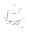
- FIG. 1 is a perspective view schematically showing a capacitor with a seat plate according to the present embodiment.
- the capacitor 1000A with a seat plate according to the present embodiment includes a capacitor body 100 and a first seat plate 200 that holds the capacitor body 100.
- the first seat plate 200 has a first surface 200X and a second surface 200Y opposite to the first surface 200X.
- the capacitor main body 100 is arranged on the second surface 200Y side of the first seat plate 200.
- the first seat plate 200 has a substantially flat plate shape, but the second surface 200Y is provided with a positioning portion 230 for positioning the capacitor body 100.
- FIG. 2A is a plan view schematically showing an example of a first seat plate viewed from the second surface side according to the present embodiment.
- the shape of the first seat plate 200A seen from the normal direction of the second surface 200Y is substantially rectangular, and the two corners are chamfered.
- the first seat plate 200A is provided with two through holes 220 through which lead terminals are inserted.
- the first heat radiating member 210A is held on the first seat plate 200A.
- the first heat radiating member 210A is embedded in the first seat plate 200A, and a part thereof is exposed from the first surface 200X side and the second surface 200Y side of the first seat plate 200, respectively.
- the first heat radiating member 210A is obtained by processing a substantially flat metal plate into, for example, a wave shape.
- the exposed shape of the first heat radiating member 210A as viewed from the second surface 200Y side corresponds to the convex portion of the wave-shaped metal plate and corresponds to a part of the open end portion of the case. As a result, the first heat radiating member 210A can come into contact with the case.
- FIG. 2B is a plan view schematically showing an example of the seat plate of FIG. 2A viewed from the first surface side.
- the first surface 200X of the first seat plate 200A is a mounting surface when a capacitor with a seat plate is mounted on a substrate or the like.
- a groove 240 for accommodating a lead terminal is provided on the first surface 200X.
- the exposed shape of the first heat radiating member 210A seen from the first surface 200X side corresponds to the recess of the wave-shaped metal plate, and corresponds to the other part of the open end of the case.
- the first heat radiating member 210A exposed on the first surface 200X side is joined to the wiring pattern of the substrate by solder or the like.
- FIG. 3A is a plan view schematically showing an example of another seat plate viewed from the second surface side according to the present embodiment.
- FIG. 3B is a plan view schematically showing an example of the seat plate of FIG. 3A viewed from the first surface side.
- the first seat plate 200B shown in FIGS. 3A and 3B has a first seat plate shown in FIGS. 2A and 2B, except for the exposed shapes on the first surface 200X side and the second surface 200Y side of the first heat radiation member 210B. It has the same configuration as 200A.
- the first heat radiating member 210B is obtained by bending a substantially flat metal plate. For example, it is formed by punching out a member provided with an annular body and two straps extending outward from the annular body from two opposite positions of the annular body from a metal plate, and bending each strap. Toroid. The tips of the straps are spread out in a substantially rectangular shape. As a result, the first heat radiating member 210B is exposed in an annular shape substantially corresponding to the opening end of the case on the second surface 200Y side, and is exposed in two places on the first surface 200X side in a substantially rectangular shape. The first heat radiating member 210B covers about 20% of the area of the first surface 200X. However, the first heat radiating member 210B is exposed on the first surface 200X side so as not to overlap both grooves 240 in which the anode lead terminals are housed.
- FIG. 4A is a plan view schematically showing an example of yet another seat plate viewed from the second surface side according to the present embodiment.
- FIG. 4B is a plan view schematically showing an example of the seat plate of FIG. 4A viewed from the first surface side.
- the first seat plate 200C shown in FIGS. 4A and 4B has the first seat plate shown in FIGS. 2A and 2B except for the exposed shapes on the first surface 200X side and the second surface 200Y side of the first heat radiation member 210C. It has the same configuration as 200A.
- the first heat dissipation member 210C is also obtained by bending a substantially flat metal plate. For example, it is formed by punching out a member provided with an annular body and two straps extending from a portion close to the annular body toward the outside of the annular body from a metal plate, and bending each strap. .. The tip of the strap extends in a substantially rectangular shape, and the two straps are connected. As a result, the first heat radiating member 210C is exposed in an annular shape substantially corresponding to the opening end of the case on the second surface 200Y side, and is exposed in a substantially rectangular shape on the first surface 200X side. The first heat radiating member 210B covers about 45% of the area of the first surface 200X.
- the first heat radiating member 210C is exposed on the first surface 200X side so as not to overlap the groove 240 on one side in which the anode lead terminal is housed.
- the first heat radiating member 210C is exposed along the other groove 240 in which the cathode lead terminal is housed.
- the first heat radiating member 210 and the cathode lead terminal can be brought into contact with each other, and the heat radiating efficiency of the capacitor is improved.
- the first heat radiating member 210 and the cathode lead terminal are more easily contacted by the conductive bonding material used when mounting the capacitor on the substrate.
- the capacitor with a seat plate includes a capacitor main body and a seat plate for holding the capacitor main body.
- the capacitor body includes a capacitor element, a case having an opening for accommodating the capacitor element, a sealing member that closes the opening of the case, and a plurality of leads that are led out to the outside of the capacitor body through the sealing member and the seat plate. It is equipped with a terminal.
- the seat plate (second seat plate) includes a base having a first surface and a second surface opposite to the first surface, and a support wall extending from the base along the peripheral surface of the case. Has. A part of the heat radiating member (second heat radiating member) is arranged on the support wall of the second seat plate. The other part of the second heat radiating member is exposed from the first surface side of the second seat plate. That is, the second heat radiating member covers the case with a wider area and thermally connects the peripheral surface of the case to the substrate on which the capacitor is mounted. As a result, the heat of the capacitor is quickly transferred to the substrate or the like via the second heat radiating member, and deterioration due to heat of the capacitor element is suppressed.
- the second seat plate has a base having first and second surfaces and a support wall extending from the base along the peripheral surface of the case.
- the base is, for example, a flat plate.
- the base may have the same shape as the first seat plate. Further, the base portion is provided with a through hole through which a lead terminal is inserted.
- the support wall extends along the peripheral surface of the case, for example, from the open end of the case toward the other end.
- the capacitor body is fitted into the support wall and fixed to the second seat plate.
- the shape of the support wall is not particularly limited.
- the support wall may have a tubular shape that covers the entire peripheral surface of the case, a tubular shape that covers a part of the peripheral surface of the case, or a columnar shape that covers a part of the peripheral surface of the case. You may. It is preferable that a plurality of columnar support walls (hereinafter, may be referred to as columns) are arranged. It is preferable that the plurality of columns are arranged point-symmetrically or substantially point-symmetrically with respect to the center of the second surface. Substantial point symmetry means that, for example, the center of gravity of each column exists at an angularly equivalent position with respect to the center of the second surface.
- the central angle formed by the centers of gravity of adjacent columns is preferably 360 / n degrees, where n is the number of columns.
- the number of columns may be, for example, 2 to 10. Considering the balance between the stability of the capacitor body and the ease of manufacturing the seat plate, the number of columns is preferably 2, 3 or 4.
- the heights of the plurality of columns may be the same or may be different.
- the material of the second seat plate is not particularly limited and may be the same as that of the first seat plate.
- the base and the support wall may be separate bodies or may be integrally molded.
- the thickness of the flat base is not particularly limited.
- the thickness of the base may be, for example, 0.2 mm or more and 2.0 mm or less.
- the thickness of the support wall is also not particularly limited.
- the thickness of the support wall may be, for example, 0.2 mm or more and 4.0 mm or less.
- a part of the heat radiating member (second heat radiating member) held by the second seat plate is arranged on the support wall.
- To be placed on the support wall means that the second heat radiating member is contained in the support wall and is not exposed from the support wall, or a part of the second heat radiating member is embedded in the support wall. It means that a part of is exposed from the support wall.
- the other portion of the second heat radiating member is arranged at the base, and the second heat radiating member arranged on the support wall and the second heat radiating member arranged at the base are heat. Is connected.
- a part of the second heat radiating member arranged at the base is exposed from the first surface side.
- the shape of the second heat radiating member is not particularly limited. From the viewpoint of miniaturization, it is desirable that the heat radiating member has a shape that does not excessively change the outer shapes of the support wall and the base. As a result, the conventionally used seat plate can be easily replaced with the seat plate according to the present embodiment.
- the second heat radiating member arranged on the support wall has, for example, a curved surface along the peripheral surface of the case.
- the second heat radiating member arranged at the base may be an integral body with the second heat radiating member arranged on the support wall, or may be a separate body. When the second heat radiating member arranged on the support wall and the base portion is an integral body, the second heat radiating member arranged on the support wall may penetrate the base portion as it is. When the support wall and the second heat radiating member arranged on the base are separate bodies, the second heat radiating member arranged on the base may be flat like the base.
- a part of the second heat radiating member is exposed from the first surface side of the second seat plate.
- the exposed shape of the second heat radiating member as viewed from the first surface side is not particularly limited.
- the exposed shape of the second heat radiating member as viewed from the first surface side may be the same as the projected shape of the second heat radiating member arranged on the support wall on the first surface. That is, the support wall and the base may be penetrated by one second heat radiating member. This tends to shorten the heat transfer path.
- the second heat radiating member is exposed as widely as possible to the first surface side in that the heat received by the exposed portion on the second surface side is easily released from the exposed portion on the first surface side. Is preferable. However, like the first heat radiation member, the second heat radiation member is exposed on the first surface side so as not to come into contact with the anode lead terminal, while the exposed portion on the first surface side is the cathode lead terminal. Is preferably in contact with.
- Such an exposed shape can be realized by separating the second heat radiating member arranged on the support wall and the second heat radiating member arranged on the base.
- the exposed portion on the first surface side of the second heat radiating member may be 5% or more of the area of the first surface, and may be 10% or more. It is desirable that the second heat radiating member is widely exposed to the first surface side within a range that does not come into contact with the anode lead terminal. From the viewpoint of preventing a short circuit, the exposed portion on the first surface side of the second heat radiating member may be 70% or less of the area of the first surface, and may be 60% or less.
- a part of the second heat radiating member may be included in the support wall.
- the second heat radiating member is not exposed from the support wall.
- a part of the second heat radiating member may be embedded in the support wall, and the other part may be exposed from the support wall.
- the material of the second heat radiating member is not particularly limited and may be the same as that of the first heat radiating member.
- the thickness of the second heat radiating member may be appropriately set according to the thickness of the support wall and / or the base.
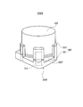
- FIG. 5 is a perspective view schematically showing a capacitor with a seat plate according to the present embodiment.
- the capacitor 1000B with a seat plate according to the present embodiment includes a capacitor body 100 and a second seat plate 300 that holds the capacitor body 100.
- the second seat plate 300 includes a base 301 having a first surface 300X and a second surface 300Y opposite to the first surface 300X, and four columnar support walls 302 extending from the base 301 along the peripheral surface of the case. And have.
- the capacitor body 100 is arranged on the second surface 300Y side of the second seat plate 300.
- Each of the four support walls 302 is provided with a second heat radiating member 310.
- the second heat radiating member 310 is a metal plate and penetrates the base 301 and the support wall 302.
- the metal plate preferably has a shape along the peripheral surface of the case, for example, a curved surface.
- a part of the second heat radiating member 310 is arranged on the support wall 302 of the second seat plate 300.
- the other part of the second heat radiating member 310 is arranged in the base 301.
- FIG. 6A is a plan view schematically showing an example of a seat plate viewed from the second surface side according to the present embodiment.
- the shape of the second seat plate 300A seen from the normal direction of the second surface 300Y is substantially rectangular, and the two corners are chamfered.
- the second seat plate 300 is provided with two through holes 320 through which lead terminals are inserted.
- the columnar support walls 302 are arranged at the four corners of the second surface 300Y, respectively, and are arranged substantially point-symmetrically with respect to the center of the second surface 300Y. The heights of the support walls 302 are the same.
- the second heat radiating member 310A is included in the support wall 302 and is not exposed from the support wall 302. Further, when viewed from the second surface 300Y side, the second heat radiating member 310A is not exposed.
- FIG. 6B is a plan view schematically showing an example of the seat plate of FIG. 6A viewed from the first surface side.
- the first surface 300X is a mounting surface when a capacitor with a seat plate is mounted on a substrate or the like.
- the first surface 300X is provided with two grooves 340 for accommodating lead terminals.
- the exposed shape of the second heat radiating member 310A seen from the first surface 300X side is the same as the projected shape of the second heat radiating member 310A arranged on the support wall 302 on the first surface 300X.
- FIG. 6C is a plan view schematically showing another example of the seat plate of FIG. 6A viewed from the first surface side.
- the second seat plate 300B shown in FIG. 6C is different from the second seat plate 300A shown in FIGS. 6A and 6B, except that the second heat radiation member 310B, which is flat and substantially rectangular, is also arranged at the base 301. It has a similar configuration.
- the exposed shape of the second heat radiating member 310B as seen from the first surface 300X side is a part of the projected shape of the second heat radiating member 310A arranged on the support wall 302 on the first surface 300X and the second heat radiating member. It is a combination with a substantially rectangular shape according to 310B.
- the second heat radiating member 310C covers about 45% of the area of the first surface 300X.
- the second heat radiating member 310B is exposed on the first surface 300X side so as not to overlap the groove 340 on one side in which the anode lead terminal is housed.
- the second heat radiating member 310B is exposed along the other groove 340 in which the cathode lead terminal is housed.
- the second heat radiating member 310B can come into contact with the cathode lead terminal, and the heat radiating efficiency of the capacitor is improved.
- the second heat radiating member 310B and the cathode lead terminal are more easily contacted by the conductive bonding material used when mounting the capacitor on the substrate.
- FIG. 7 is a plan view schematically showing another example of the seat plate viewed from the second surface side according to the present embodiment.
- the second seat plate 300C shown in FIG. 7 has the same configuration as the seat plate shown in FIGS. 6A and 6B, except that the second heat radiating member 310C is exposed from the case-side surface of the support wall 302. ..
- a part of the second heat radiating member 310C is embedded in the support wall 302, but a part is exposed from the case side surface of the support wall 302. Therefore, the second heat radiating member 310C can come into contact with the case, and the heat radiating property is further improved.
- the capacitor element includes, for example, an anode body having a dielectric layer, a cathode body, and a solid electrolyte interposed between the anode body and the cathode body.
- anode body having a dielectric layer for example, an aluminum oxide layer, a copper oxide layer, and a zinc oxide layer.
- a cathode body having a dielectric layer for example, an aluminum oxide layer, a copper oxide film, and a solid electrolyte interposed between the anode body and the cathode body.
- a foil-shaped anode body and a foil-shaped cathode body are spirally wound.
- the anode is a metal leaf containing at least one valve acting metal such as titanium, tantalum, aluminum and niobium.
- the anode body may contain the valve acting metal in the form of an alloy containing the valve acting metal, a compound containing the valve acting metal, or the like.
- the thickness of the anode body is not particularly limited, and is, for example, 15 ⁇ m or more and 300 ⁇ m or less. The thickness is an average value at any five points (hereinafter, the same applies).
- the surface of the anode body may be roughened by etching or the like.
- a dielectric layer is formed on the surface of the anode body.
- the dielectric layer is formed, for example, by chemical conversion treatment of the anode body.
- the dielectric layer may contain oxides of the valvening metal.
- the dielectric layer is not limited to this, and may be any one that functions as a dielectric.
- the cathode body may have a function as a cathode, and is not particularly limited.
- the cathode body may be a metal foil.
- the type of metal is not particularly limited, and may be a valve acting metal or an alloy containing a valve acting metal like an anode body, or may be other than a valve acting metal such as iron (Fe) and copper (Cu).
- the thickness of the cathode body is not particularly limited, and is, for example, 15 ⁇ m or more and 300 ⁇ m or less.
- the surface of the cathode body may be roughened or chemical-treated, if necessary. Further, an inorganic layer containing carbon, nickel, titanium, and oxides or nitrides thereof may be formed on the surface of the cathode body.
- a separator may be interposed between the anode body and the cathode body. If a solid electrolyte of sufficient thickness is placed between the anode and the cathode, the separator may be omitted.
- the separator is not particularly limited as long as it is porous.
- Examples of the separator include a non-woven fabric made of cellulose fiber, a non-woven fabric made of glass fiber, a microporous film made of polyolefin, a woven fabric, and a non-woven fabric.
- the thickness of the separator is not particularly limited, and is, for example, 10 ⁇ m or more and 300 ⁇ m or less.
- the solid electrolyte includes, for example, a conductive polymer.
- a conductive polymer examples include polypyrrole, polythiophene, polyfuran, polyaniline, polyacetylene, polyphenylene, polyphenylene vinylene, polyacene, polythiophene vinylene and the like. These may be used alone, in combination of two or more, or in a copolymer of two or more monomers.
- polypyrrole, polythiophene, polyfuran, polyaniline, etc. mean macromolecules having polypyrrole, polythiophene, polyfuran, polyaniline, etc. as their basic skeletons, respectively. Therefore, polypyrrole, polythiophene, polyfuran, polyaniline and the like may also contain their respective derivatives.
- polythiophene includes poly (3,4-ethylenedioxythiophene) and the like.
- the solid electrolyte may contain a dopant together with the conductive polymer.
- the dopant may be a monomolecular anion or a polymer anion.
- Specific examples of the monomolecular anion include paratoluenesulfonic acid and naphthalenesulfonic acid.
- Specific examples of the high molecular weight anion include polyvinyl sulfonic acid, polystyrene sulfonic acid, polyallyl sulfonic acid, polyacrylic sulfonic acid, polymethacrylic sulfonic acid, poly (2-acrylamide-2-methylpropanesulfonic acid), and polyisoprene sulfonic acid. , Polyacrylic acid and the like.
- These may be used alone or in combination of two or more. Further, these may be polymers of a single monomer or may be a copolymer of two or more kinds of monomers. Of these, a polymer anion derived from polystyrene sulfonic acid is preferable.
- An anode lead terminal is connected to the anode body, and a cathode lead terminal is connected to the cathode body.
- the anode lead terminal and the cathode lead terminal penetrate the sealing member and the seat plate and are led out to the outside of the capacitor body.
- the derived lead terminal is, for example, bent along the first surface of the seat plate and housed in a groove provided on the first surface of the seat plate.
- the material of the lead terminal is not particularly limited as long as it is electrochemically and chemically stable and has conductivity, and may be metal or non-metal.
- the shape is also not particularly limited.
- the sealing member closes the opening of the case.
- the sealing member may be an insulating substance.
- An elastic body is preferable as the insulating substance.
- High sealing performance can be ensured by using a sealing member containing an elastic body such as rubber. From the viewpoint that high heat resistance can be easily obtained, silicone rubber, fluororubber, ethylene propylene rubber, chlorosulfonated polyethylene rubber (hypalon rubber, etc.), butyl rubber, isoprene rubber and the like are preferable.
- the case has an opening for accommodating the capacitor element.
- the case comprises, for example, a tubular portion and a bottom wall that closes one end of the tubular portion. The other end (open end) of the tubular portion is closed by the sealing member and arranged on the seat plate side.
- the outer shape of the case is, for example, cylindrical or substantially cylindrical.
- the open end of the cylinder covers, for example, the peripheral edge of the surface of the sealing member on the seat plate side.
- Such an opening end portion is formed by caulking the opening end portion and the sealing member.
- the portion of the heat radiating member exposed from the second surface side comes into contact with, for example, the opening end portion that covers the peripheral edge of the surface of the sealing member on the seat plate side.
- an annular recess may be formed on the opening end side of the cylinder portion so as to reduce the inner diameter of the cylinder portion.
- the annular recess is formed by drawing a cylinder for fixing the sealing member to the case.
- the material of the case is not particularly limited, and examples thereof include metals such as aluminum, aluminum alloy, stainless steel, copper, iron, and brass.
- a surface layer having a desired function (for example, an oxide layer, a resin layer, etc.) may be formed on the outer surface of the case.
- FIG. 8 is a vertical cross-sectional view schematically showing a capacitor with a seat plate according to the present embodiment.
- FIG. 8 shows a capacitor with a second seat plate having a support wall.
- the capacitor 1000B with a seat plate includes a capacitor body 100 and a seat plate (second seat plate 300) for holding the capacitor body 100.
- the capacitor body 100 penetrates the capacitor element 10, the case 20 having an opening for accommodating the capacitor element 10, the sealing member 30 that closes the opening of the case 20, the sealing member 30, and the second seat plate 300. It includes two lead terminals 40 that are led out to the outside of the capacitor body 100.
- the second seat plate 300 has a base 301 and a support wall 302 extending from the base 301 along the peripheral surface of the case 20.
- a heat radiating member (not shown) is arranged on the base 301 and the support wall 302.
- the present invention is particularly suitable for electrolytic capacitors in which a high ripple current flows because it has excellent heat dissipation.
Landscapes
- Engineering & Computer Science (AREA)
- Power Engineering (AREA)
- Microelectronics & Electronic Packaging (AREA)
- Chemical & Material Sciences (AREA)
- Chemical Kinetics & Catalysis (AREA)
- Electrochemistry (AREA)
- Cooling Or The Like Of Electrical Apparatus (AREA)
- Electric Double-Layer Capacitors Or The Like (AREA)
- Fixed Capacitors And Capacitor Manufacturing Machines (AREA)
Priority Applications (3)
| Application Number | Priority Date | Filing Date | Title |
|---|---|---|---|
| JP2021542967A JPWO2021039849A1 (https=) | 2019-08-30 | 2020-08-26 | |
| CN202080059814.6A CN114303214B (zh) | 2019-08-30 | 2020-08-26 | 带座板电容器 |
| US17/649,799 US12119177B2 (en) | 2019-08-30 | 2022-02-03 | Capacitor with seat plate |
Applications Claiming Priority (2)
| Application Number | Priority Date | Filing Date | Title |
|---|---|---|---|
| JP2019-158329 | 2019-08-30 | ||
| JP2019158329 | 2019-08-30 |
Related Child Applications (1)
| Application Number | Title | Priority Date | Filing Date |
|---|---|---|---|
| US17/649,799 Continuation US12119177B2 (en) | 2019-08-30 | 2022-02-03 | Capacitor with seat plate |
Publications (1)
| Publication Number | Publication Date |
|---|---|
| WO2021039849A1 true WO2021039849A1 (ja) | 2021-03-04 |
Family
ID=74685040
Family Applications (1)
| Application Number | Title | Priority Date | Filing Date |
|---|---|---|---|
| PCT/JP2020/032204 Ceased WO2021039849A1 (ja) | 2019-08-30 | 2020-08-26 | 座板付きコンデンサ |
Country Status (4)
| Country | Link |
|---|---|
| US (1) | US12119177B2 (https=) |
| JP (1) | JPWO2021039849A1 (https=) |
| CN (1) | CN114303214B (https=) |
| WO (1) | WO2021039849A1 (https=) |
Families Citing this family (2)
| Publication number | Priority date | Publication date | Assignee | Title |
|---|---|---|---|---|
| CN115050574A (zh) * | 2022-06-18 | 2022-09-13 | 丰宾电子(深圳)有限公司 | 一种电容器矮腰抗震座板 |
| TWI872617B (zh) * | 2023-07-25 | 2025-02-11 | 鈺邦科技股份有限公司 | 可移動裝置及其捲繞型電容器封裝結構 |
Citations (5)
| Publication number | Priority date | Publication date | Assignee | Title |
|---|---|---|---|---|
| JP2007287777A (ja) * | 2006-04-13 | 2007-11-01 | Matsushita Electric Ind Co Ltd | 縦型チップコンデンサ |
| JP2007300040A (ja) * | 2006-05-08 | 2007-11-15 | Matsushita Electric Ind Co Ltd | 縦型チップコンデンサ用座板の製造方法 |
| JP2010205995A (ja) * | 2009-03-04 | 2010-09-16 | Hitachi Kokusai Electric Inc | プリント基板 |
| JP2012138414A (ja) * | 2010-12-24 | 2012-07-19 | San Denshi Kogyo Kk | チップ形コンデンサ及びその製造方法 |
| JP2019096847A (ja) * | 2017-11-28 | 2019-06-20 | ニチコン株式会社 | コンデンサ |
Family Cites Families (18)
| Publication number | Priority date | Publication date | Assignee | Title |
|---|---|---|---|---|
| JPS63159817U (https=) | 1987-04-09 | 1988-10-19 | ||
| JPH06104143A (ja) * | 1992-09-21 | 1994-04-15 | Nippon Chemicon Corp | 電解コンデンサの取付装置 |
| JP3639398B2 (ja) * | 1996-04-10 | 2005-04-20 | ニチコン株式会社 | 電解コンデンサ |
| JP3750952B2 (ja) * | 1996-04-10 | 2006-03-01 | ニチコン株式会社 | 電解コンデンサ |
| US6735074B2 (en) * | 2000-02-03 | 2004-05-11 | Matsushita Electric Industrial Co., Ltd. | Chip capacitor |
| US6452784B2 (en) * | 2000-05-31 | 2002-09-17 | Matsushita Electric Industrial Co., Ltd. | Aluminum electrolytic capacitor and method for producing the same |
| JP2006287100A (ja) * | 2005-04-04 | 2006-10-19 | Shindengen Electric Mfg Co Ltd | コンデンサモジュール |
| JP2006310610A (ja) * | 2005-04-28 | 2006-11-09 | Toyo Denji Kikai Seisakusho:Kk | 電解コンデンサ及び電解コンデンサ用アルミケース |
| JP4557956B2 (ja) | 2006-11-20 | 2010-10-06 | ルビコン株式会社 | 絶縁性支持体を備えた電子部品 |
| JP2008244033A (ja) * | 2007-03-27 | 2008-10-09 | Nippon Chemicon Corp | チップ型コンデンサ |
| EP2015322A1 (en) * | 2007-07-13 | 2009-01-14 | Panasonic Corporation | Capacitor module with optimized heat transmission |
| US7532484B1 (en) * | 2008-02-11 | 2009-05-12 | Delphi Technologies, Inc. | Electronic component assembly |
| JP2014229725A (ja) * | 2013-05-22 | 2014-12-08 | パナソニック株式会社 | 蓄電ユニットおよびそれに用いられる蓄電装置 |
| JP6589142B2 (ja) * | 2014-05-16 | 2019-10-16 | パナソニックIpマネジメント株式会社 | 電解コンデンサの製造方法 |
| JP6472970B2 (ja) | 2014-10-06 | 2019-02-20 | ニチコン株式会社 | 面実装型コンデンサおよびこれに用いられる座板 |
| JP6813259B2 (ja) * | 2015-06-29 | 2021-01-13 | 富士電機株式会社 | 半導体装置 |
| JP2018137267A (ja) * | 2017-02-20 | 2018-08-30 | 富士通株式会社 | 電子部品 |
| DE102019119538B8 (de) * | 2019-07-18 | 2025-10-16 | Tdk Electronics Ag | Kondensator und Anordnung mit Leiterplatte und Kondensator |
-
2020
- 2020-08-26 WO PCT/JP2020/032204 patent/WO2021039849A1/ja not_active Ceased
- 2020-08-26 CN CN202080059814.6A patent/CN114303214B/zh active Active
- 2020-08-26 JP JP2021542967A patent/JPWO2021039849A1/ja active Pending
-
2022
- 2022-02-03 US US17/649,799 patent/US12119177B2/en active Active
Patent Citations (5)
| Publication number | Priority date | Publication date | Assignee | Title |
|---|---|---|---|---|
| JP2007287777A (ja) * | 2006-04-13 | 2007-11-01 | Matsushita Electric Ind Co Ltd | 縦型チップコンデンサ |
| JP2007300040A (ja) * | 2006-05-08 | 2007-11-15 | Matsushita Electric Ind Co Ltd | 縦型チップコンデンサ用座板の製造方法 |
| JP2010205995A (ja) * | 2009-03-04 | 2010-09-16 | Hitachi Kokusai Electric Inc | プリント基板 |
| JP2012138414A (ja) * | 2010-12-24 | 2012-07-19 | San Denshi Kogyo Kk | チップ形コンデンサ及びその製造方法 |
| JP2019096847A (ja) * | 2017-11-28 | 2019-06-20 | ニチコン株式会社 | コンデンサ |
Also Published As
| Publication number | Publication date |
|---|---|
| US20220157521A1 (en) | 2022-05-19 |
| CN114303214B (zh) | 2025-12-16 |
| US12119177B2 (en) | 2024-10-15 |
| JPWO2021039849A1 (https=) | 2021-03-04 |
| CN114303214A (zh) | 2022-04-08 |
Similar Documents
| Publication | Publication Date | Title |
|---|---|---|
| US8520366B2 (en) | Solid electrolytic capacitor and method of manufacture | |
| JP7113285B2 (ja) | 電解コンデンサ | |
| CN1918677B (zh) | 固体电解电容器 | |
| JP6400909B2 (ja) | コンデンサ及びコンデンサの設置方法 | |
| US12119177B2 (en) | Capacitor with seat plate | |
| WO2003077268A1 (fr) | Condensateur electrolytique solide | |
| CN101176172B (zh) | 层叠型固体电解电容器及其制造方法 | |
| US20210161028A1 (en) | Heat equalization plate and method for manufacturing the same | |
| KR100623804B1 (ko) | 고체 전해질 캐패시터 및 그 제조방법 | |
| US20180012704A1 (en) | Power storage device | |
| CN115280442B (zh) | 电解电容器 | |
| WO2019167772A1 (ja) | 電解コンデンサモジュール | |
| CN102576609A (zh) | 电解电容器 | |
| JP2020088346A (ja) | 電解コンデンサ | |
| US12255026B2 (en) | Electrolytic capacitor | |
| CN108140489B (zh) | 固体电解电容器 | |
| JP2002237431A (ja) | 固体電解コンデンサ及びその製造方法 | |
| JP2013038298A (ja) | フィルムコンデンサ | |
| JPWO2014038203A1 (ja) | 固体電解コンデンサ | |
| CN118315193A (zh) | 一种电容器 | |
| JP2005210024A (ja) | コンデンサ | |
| WO2023162602A1 (ja) | コンデンサアセンブリ | |
| US20090290289A1 (en) | Solid electrolytic capacitor and manufacturing method thereof | |
| JP2014135328A (ja) | ケース外装型コンデンサ | |
| JP2007317784A (ja) | 固体電解コンデンサ |
Legal Events
| Date | Code | Title | Description |
|---|---|---|---|
| 121 | Ep: the epo has been informed by wipo that ep was designated in this application |
Ref document number: 20859126 Country of ref document: EP Kind code of ref document: A1 |
|
| WWE | Wipo information: entry into national phase |
Ref document number: 2021542967 Country of ref document: JP |
|
| NENP | Non-entry into the national phase |
Ref country code: DE |
|
| 122 | Ep: pct application non-entry in european phase |
Ref document number: 20859126 Country of ref document: EP Kind code of ref document: A1 |