WO2021039697A1 - 変倍光学系、光学機器および変倍光学系の製造方法 - Google Patents
変倍光学系、光学機器および変倍光学系の製造方法 Download PDFInfo
- Publication number
- WO2021039697A1 WO2021039697A1 PCT/JP2020/031788 JP2020031788W WO2021039697A1 WO 2021039697 A1 WO2021039697 A1 WO 2021039697A1 JP 2020031788 W JP2020031788 W JP 2020031788W WO 2021039697 A1 WO2021039697 A1 WO 2021039697A1
- Authority
- WO
- WIPO (PCT)
- Prior art keywords
- lens group
- focusing
- optical system
- focusing lens
- variable magnification
- Prior art date
Links
Images


Classifications
-
- G—PHYSICS
- G02—OPTICS
- G02B—OPTICAL ELEMENTS, SYSTEMS OR APPARATUS
- G02B15/00—Optical objectives with means for varying the magnification
- G02B15/14—Optical objectives with means for varying the magnification by axial movement of one or more lenses or groups of lenses relative to the image plane for continuously varying the equivalent focal length of the objective
- G02B15/146—Optical objectives with means for varying the magnification by axial movement of one or more lenses or groups of lenses relative to the image plane for continuously varying the equivalent focal length of the objective having more than five groups
- G02B15/1461—Optical objectives with means for varying the magnification by axial movement of one or more lenses or groups of lenses relative to the image plane for continuously varying the equivalent focal length of the objective having more than five groups the first group being positive
-
- G—PHYSICS
- G02—OPTICS
- G02B—OPTICAL ELEMENTS, SYSTEMS OR APPARATUS
- G02B15/00—Optical objectives with means for varying the magnification
- G02B15/14—Optical objectives with means for varying the magnification by axial movement of one or more lenses or groups of lenses relative to the image plane for continuously varying the equivalent focal length of the objective
- G02B15/142—Optical objectives with means for varying the magnification by axial movement of one or more lenses or groups of lenses relative to the image plane for continuously varying the equivalent focal length of the objective having two groups only
- G02B15/1421—Optical objectives with means for varying the magnification by axial movement of one or more lenses or groups of lenses relative to the image plane for continuously varying the equivalent focal length of the objective having two groups only the first group being positive
-
- G—PHYSICS
- G02—OPTICS
- G02B—OPTICAL ELEMENTS, SYSTEMS OR APPARATUS
- G02B15/00—Optical objectives with means for varying the magnification
- G02B15/14—Optical objectives with means for varying the magnification by axial movement of one or more lenses or groups of lenses relative to the image plane for continuously varying the equivalent focal length of the objective
- G02B15/16—Optical objectives with means for varying the magnification by axial movement of one or more lenses or groups of lenses relative to the image plane for continuously varying the equivalent focal length of the objective with interdependent non-linearly related movements between one lens or lens group, and another lens or lens group
-
- G—PHYSICS
- G02—OPTICS
- G02B—OPTICAL ELEMENTS, SYSTEMS OR APPARATUS
- G02B27/00—Optical systems or apparatus not provided for by any of the groups G02B1/00 - G02B26/00, G02B30/00
- G02B27/0012—Optical design, e.g. procedures, algorithms, optimisation routines
-
- G—PHYSICS
- G02—OPTICS
- G02B—OPTICAL ELEMENTS, SYSTEMS OR APPARATUS
- G02B15/00—Optical objectives with means for varying the magnification
- G02B15/14—Optical objectives with means for varying the magnification by axial movement of one or more lenses or groups of lenses relative to the image plane for continuously varying the equivalent focal length of the objective
- G02B15/16—Optical objectives with means for varying the magnification by axial movement of one or more lenses or groups of lenses relative to the image plane for continuously varying the equivalent focal length of the objective with interdependent non-linearly related movements between one lens or lens group, and another lens or lens group
- G02B15/20—Optical objectives with means for varying the magnification by axial movement of one or more lenses or groups of lenses relative to the image plane for continuously varying the equivalent focal length of the objective with interdependent non-linearly related movements between one lens or lens group, and another lens or lens group having an additional movable lens or lens group for varying the objective focal length
Definitions
- the present invention relates to a variable magnification optical system, an optical instrument, and a method for manufacturing the variable magnification optical system.
- a zoom lens suitable for photographic cameras, electronic still cameras, video cameras, etc.
- a zoom lens has been proposed in which a part of a lens group (rear group) arranged near the image plane is moved to focus.
- a zoom lens it is required to suppress various aberrations such as curvature of field and realize good optical performance at the time of focusing.
- the first variable magnification optical system includes a preceding lens group and a succeeding lens group arranged in order from the object side along the optical axis, and the succeeding lens group is a first focusing lens having a positive refractive power.
- the group and a second focusing lens group having a negative refractive power arranged on the image plane side of the first focusing lens group are included.
- the second focusing lens group moves to the image plane side with different trajectories, and satisfies the following conditional expression.
- fF2 Focal length of the second focusing lens group
- ft Focal length of the variable magnification optical system in the telephoto end state
- the second variable magnification optical system comprises a preceding lens group and a succeeding lens group arranged in order from the object side along the optical axis, and the preceding lens group is sequentially arranged from the object side along the optical axis.
- the following lens group includes a first lens group having a positive refractive force and a second lens group having a negative refractive force
- the subsequent lens group includes a first focusing lens group having a positive refractive force and the above-mentioned Includes a second focusing lens group having a negative refractive force arranged on the image plane side of the first focusing lens group, and adjacent lenses when scaling from the wide-angle end state to the telephoto end state.
- the first focusing lens group and the second focusing lens group move toward the object side with different trajectories, and when focusing from an infinity object to a short-range object, The first focusing lens group and the second focusing lens group move to the image plane side with different trajectories.
- the third variable magnification optical system consists of a preceding lens group and a succeeding lens group arranged in order from the object side along the optical axis, and the succeeding lens group is a first focusing having a positive refractive power. It includes a lens group and a second focusing lens group having a negative refractive power arranged on the image plane side of the first focusing lens group.
- the second focusing lens group moves to the image plane side with different trajectories.
- the second focusing lens group includes one positive lens and one negative lens arranged in order from the object side.
- the optical device according to the present invention is configured to include the above variable magnification optical system.
- each lens group is configured and arranged in a lens barrel as follows.
- the variable magnification optical system consists of a leading lens group and a trailing lens group arranged in order from the object side along the optical axis, and the trailing lens group includes a first focusing lens group having a positive refractive power and a first focusing lens group. It includes a second focusing lens group having a negative refractive power arranged on the image plane side of the lens group.
- the second focusing lens group moves to the image plane side with different trajectories, and satisfies the following conditional expression. 0.05 ⁇ (-fF2) / ft ⁇ 0.50
- fF2 Focal length of the second focusing lens group
- ft Focal length of the variable magnification optical system in the telephoto end state
- the second method for manufacturing a variable magnification optical system is as follows, in which each lens group is configured and arranged in a lens barrel.
- the leading lens group and the succeeding lens group are arranged in order from the object side along the optical axis.
- the leading lens group includes a first lens group having a positive refractive power and a second lens group having a negative refractive power arranged in order from the object side along the optical axis.
- the subsequent lens group includes a first focusing lens group having a positive refractive power and a second focusing lens group having a negative refractive power arranged on the image plane side of the first focusing lens group. To do.
- the lens group moves so that the first focusing lens group and the second focusing lens group move toward the image plane with different trajectories.
- the third method for manufacturing a variable magnification optical system is as follows, in which each lens group is configured and arranged in a lens barrel.
- the leading lens group and the succeeding lens group are arranged in order from the object side along the optical axis.
- the subsequent lens group includes a first focusing lens group having a positive refractive power and a second focusing lens group having a negative refractive power arranged on the image plane side of the first focusing lens group.
- the lens group is configured so that the second focusing lens group moves toward the image plane side with different trajectories.
- the second focusing lens group has one positive lens and one negative lens arranged in order from the object side.
- FIG. It is a diagram of various aberrations at the time of focusing an object at infinity of the variable magnification optical system according to the first embodiment, (A) is an aberration value in a wide-angle end state, (B) is an aberration value in an intermediate focal length, and (C). Indicates various aberration values in the telephoto end state. It is a diagram of various aberrations at the time of focusing on a close-range object of the variable magnification optical system according to the first embodiment, (A) is an aberration value in a wide-angle end state, (B) is an aberration value in an intermediate focal length, and (C).
- FIG. It is a diagram of various aberrations at the time of focusing on a close-range object of the variable magnification optical system according to the second embodiment, ((A) is various aberration values in the wide-angle end state, (B) is various aberration values in the intermediate focal length, (C). ) Indicates various aberration values in the telephoto end state. It is a figure which shows the lens structure of the variable magnification optical system which concerns on Example 3.
- FIG. It is a diagram of various aberrations at the time of focusing an object at infinity of the variable magnification optical system according to the third embodiment, (A) is an aberration value in a wide-angle end state, (B) is an aberration value in an intermediate focal length, (C).
- (A) is an aberration value in a wide-angle end state
- (B) is an aberration value in an intermediate focal length
- (C). Indicates various aberration values in the telephoto end state.
- (A) is an aberration value in a wide-angle end state
- (B) is an aberration value in an intermediate focal length
- (C) Indicates various aberration values in the telephoto end state.
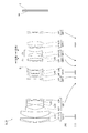
- FIG. 13 shows a schematic configuration of a digital camera, which is an embodiment of an optical device.
- the digital camera 1 is composed of a main body 2 and a photographing lens 3 that can be attached to and detached from the main body 2.
- the main body 2 includes an image sensor 4, a main body control unit (not shown) that controls the operation of a digital camera, and a liquid crystal operation screen 5.
- the photographing lens 3 includes a variable magnification optical system ZL composed of a plurality of lens groups and a lens position control mechanism (not shown) for controlling the position of each lens group.
- the lens position control mechanism is composed of a sensor that detects the position of the lens group, a motor that moves the lens group back and forth along the optical axis, a control circuit that drives the motor, and the like.
- variable magnification optical system ZL of the photographing lens 3 The light from the subject is collected by the variable magnification optical system ZL of the photographing lens 3 and reaches the image plane I of the image sensor 4.
- the light from the subject that has reached the image plane I is photoelectrically converted by the image sensor 4 and recorded as digital image data in a memory (not shown).
- the digital image data recorded in the memory is displayed on the liquid crystal screen 5 according to the user's operation.
- the variable magnification optical system ZL will be described in detail.
- the variable magnification optical system of the first embodiment consists of a preceding lens group and a succeeding lens group arranged in order from the object side along the optical axis, and the succeeding lens group includes a first focusing lens group having a positive refractive power. , Includes a second focusing lens group having a negative refractive power arranged on the image plane side of the first focusing lens group.
- the distance between adjacent lens groups changes, and at the time of focusing from an infinity object to a short-range object, the position of the preceding lens group is fixed, and it becomes the first focusing lens group.
- the second focusing lens group moves to the image plane side with different trajectories, and satisfies the following conditional equation (1).
- fF2 Focal length of the second focusing lens group
- ft Focal length of the variable magnification optical system in the telephoto end state
- Conditional expression (1) defines the ratio between the focal length of the second focusing lens group and the focal length of the variable magnification optical system in the telephoto end state, and determines the appropriate range of power of the second focusing lens group. Shown.
- various aberrations such as curvature of field, spherical aberration, and chromatic aberration can be satisfactorily corrected when focusing from an infinity object to a close-range object, and aberration fluctuations can be effectively suppressed. it can.
- the upper limit of the conditional expression (1) is a smaller value, for example, 0.45, 0.40, 0.38, 0.35, 0.33, It is preferably 0.30, 0.28, or 0.25.
- the lower limit of the conditional expression (1) is set to a larger value, for example, 0.08, 0.10, 0.13, 0.15, or 0,18. Is preferable.
- variable magnification optical system of the first embodiment can satisfactorily correct various aberrations over the entire range from the wide-angle end state to the telephoto end state by satisfying the above conditional expression with the above configuration, and can focus at a short distance. High optical performance can be achieved at times.
- variable magnification optical system of the second embodiment consists of a leading lens group and a succeeding lens group arranged in order from the object side along the optical axis, and the leading lens group is arranged in order from the object side along the optical axis.
- a first lens group having a positive refractive power and a second lens group having a negative refractive power are included, and subsequent lens groups include a first focusing lens group having a positive refractive power and a first focusing lens. It includes a second focusing lens group having a negative refractive force arranged on the image plane side of the group.
- the distance between adjacent lens groups changes, and the first in-focus lens group and the second in-focus lens group move toward the object with different trajectories.
- the first focusing lens group and the second focusing lens group move to the image plane side with different trajectories.
- variable magnification optical system of the second embodiment can satisfactorily correct various aberrations over the entire range from the wide-angle end state to the telephoto end state, and realizes high optical performance even during short-distance focusing. can do.
- the variable magnification optical system of the third embodiment consists of a preceding lens group and a succeeding lens group arranged in order from the object side along the optical axis, and the succeeding lens group is a first focusing lens group having a positive refractive power. And a second focusing lens group having a negative refractive power arranged on the image plane side of the first focusing lens group.
- the second focusing lens group moves to the image plane side with different trajectories.
- the second focusing lens group includes one positive lens and one negative lens arranged in order from the object side.
- variable magnification optical system of the third embodiment focusing is mainly performed by the movement of the second focusing lens group, and the aberration fluctuating due to the movement of the second focusing lens group is corrected by the first focusing lens group.
- the lens In a variable magnification optical system having such a configuration, if the second focusing lens group is composed of one lens, it becomes difficult to satisfactorily correct various aberrations, and as the number of lenses increases, the focusing lens group becomes heavy. It becomes difficult to realize high-speed focusing. On the other hand, when the second focusing lens group has one positive lens and one negative lens, fluctuations in various aberrations such as chromatic aberration can be suppressed even if the lens group is moved significantly. It is possible to realize high-speed focusing by reducing the size and weight of the focusing lens group, and there is an advantage that the image plane movement coefficient can be lowered.
- the above configuration is particularly suitable for telephoto lenses or high magnification lenses.
- the lenses constituting the second focusing lens group in the order of the positive lens and the negative lens, various aberrations can be corrected better than the configuration in which the lenses are arranged in the order of negative and positive.
- the off-axis light rays passing through the negative lens are separated from the optical axis and the height of the light rays passing through the positive lens is also increased, which makes it difficult to correct the aberration.
- the height of the light beam passing through the positive lens also rises, which makes it difficult to correct spherical aberration.
- the second focusing lens group preferably has one positive lens and one negative lens arranged side by side from the object side. ..
- variable magnification optical system of the third embodiment further preferably satisfies the following conditional expression (2).
- the variable magnification optical system of the first embodiment and the second embodiment further preferably satisfies the following conditional expression (2).
- ⁇ d Abbe number of positive lenses constituting the second focusing lens group
- Conditional expression (2) defines an appropriate range of Abbe numbers of the positive lenses constituting the second focusing lens group. By satisfying this conditional expression, chromatic aberration can be satisfactorily corrected. If the corresponding value of the conditional expression (2) exceeds the upper limit value of 37.00, it becomes difficult to satisfactorily correct axial chromatic aberration and chromatic aberration of magnification. In order to ensure the effect of the present embodiment, it is preferable that the upper limit value of the conditional expression (2) is a smaller value, for example, 33.00 or 29.00.
- variable magnification optical system of the third embodiment further preferably satisfies the following conditional expression (3).
- the variable magnification optical system of the first embodiment and the second embodiment further preferably satisfies the following conditional expression (3). 0.80 ⁇ NdF2n / NdF2p ⁇ 1.25 ... (3)
- NdF2n Refractive index of the negative lens constituting the second focusing lens group with respect to the d line
- NdF2p Refractive index of the positive lens constituting the second focusing lens group with respect to the d line
- Conditional expression (3) defines the ratio of the refractive indexes of the negative lens and the positive lens constituting the second focusing lens group, and indicates a preferable combination of the two lenses.
- the upper limit of the conditional expression (3) is set to a smaller value, for example, 1.23, 1.20, 1.18, 1.15, or 1.11. Is preferable.
- the lower limit of the conditional expression (3) is set to a larger value, for example, 0.83, 0.85, 0.88, 0.90, 0.92, Alternatively, it is preferably 0.95.
- variable magnification optical system of the first to third embodiments further satisfies the following conditional expression (4).
- MF1t Amount of movement when focusing from an infinity object of the first focusing lens group to a close-range object in the telephoto end state
- MF2t Close distance from the infinity object of the second focusing lens group in the telephoto end state Amount of movement when focusing on an object (The amount of movement represents the movement toward the image plane as a positive value.)
- Conditional expression (4) defines the ratio of the amount of movement of the two focusing lens groups when focusing from an infinity object to a close-range object.
- the focusing lens group is largely changed, the fluctuation of the aberration becomes large.
- various aberrations can be satisfactorily corrected and the fluctuation of the aberration at the time of focusing can be effectively suppressed.
- the upper limit of the conditional expression (4) is set to a smaller value, for example, 0.38, 0.35, 0.34, 0.30, 0.28, Alternatively, it is preferably 0.25.
- the lower limit of the conditional expression (4) may be set to a larger value, for example, 0.06, 0.08, 0.10, or 0.11. preferable.
- variable magnification optical system of the first to third embodiments further satisfies the following conditional expression (5). 0.04 ⁇ F1t / ⁇ F2t ⁇ 0.20 ... (5)
- ⁇ F1t Lateral magnification when the first in-focus lens group is in focus at the telephoto end state
- F2t Lateral magnification when the second in-focus lens group is in focus at the telephoto end state
- Conditional expression (5) defines the ratio of the lateral magnification of the first focusing lens group and the second focusing lens group when focusing on an infinity object at the telephoto end.
- the upper limit of the conditional expression (5) may be set to a smaller value, for example, 0.18, 0.16, 0.15, or 0.14. preferable.
- the corresponding value of the conditional expression (5) is less than the lower limit value of 0.04, the lateral magnification of the first focusing lens group becomes relatively small, and it becomes difficult to correct curvature of field and non-point distance difference.
- variable magnification optical system of the first to third embodiments has a rear lens group arranged adjacent to the second focusing lens group on the image plane side of the second focusing lens group, and has the following conditional expression. It is preferable to satisfy (6). 0.05 ⁇ F1w / ⁇ LGw ⁇ 2.50 ... (6) However, ⁇ F1w: Lateral magnification of the first focusing lens group when focusing on an infinity object in the wide-angle end state ⁇ LGw: Lateral magnification of the rear lens group when focusing on an infinity object in the wide-angle end state
- Conditional expression (6) defines the ratio between the lateral magnification of the first focusing lens group when focusing on an infinity object in the wide-angle end state and the lateral magnification of the rear lens group when focusing on an infinity object in the wide-angle end state. To do. By satisfying this conditional expression, various aberrations can be satisfactorily corrected without enlarging the optical system.
- the upper limit of the conditional expression (6) is set to a smaller value, for example, 2.45, 2.40, 2.38, 2.35, 2.30, It is preferably 2.25, 2.20, 2.00, 1.80, 1.60, or 1.50.
- variable magnification optical system of the first to third embodiments further satisfies the following conditional expression (7). 0.40 ⁇ (-fF2) /fF1 ⁇ 0.80 ... (7)
- fF1 Focal length of the first focusing lens group
- fF2 Focal length of the second focusing lens group
- Conditional formula (7) defines the ratio of the focal lengths of the first focusing lens group and the second focusing lens group, and indicates an appropriate range of the power balance of the two focusing lens groups.
- the upper limit of the conditional expression (7) is set to a smaller value, for example, 0.78, 0.75, 0.73, 0.70, or 0.68. Is preferable.
- the lower limit of the conditional expression (7) is set to a larger value, for example, 0.43, 0.45, 0.48, 0.50, 0.53, It is preferably 0.55 or 0.58.
- variable magnification optical system of the first to third embodiments has a configuration in which a lens component having a negative refractive power is arranged at a position closest to the image plane of the subsequent lens group.
- the "lens component” means that the lens may be either a single lens or a junction lens.
- variable magnification optical system of the first to third embodiments has a diaphragm arranged on the optical axis, and the first focusing lens group and the second focusing lens group are closer to the image plane than the diaphragm. It is preferable that they are arranged in close positions. As a result, the fluctuation of the magnification at the time of focusing can be reduced, and the spherical aberration and the curvature of field can be corrected in a well-balanced manner.
- variable magnification optical system of the first to third embodiments it is preferable to arrange the first focusing lens group and the second focusing lens group so as to be adjacent to each other. As a result, fluctuations in spherical aberration and curvature of field during focusing can be satisfactorily suppressed.
- variable magnification optical system of the first to third embodiments further satisfies the following conditional expression (8).
- ⁇ F1 Lateral magnification when focusing on an infinity object of the first focusing lens group in the wide-angle end state
- Conditional expression (8) defines the lateral magnification of the first focusing lens group when focusing on an infinite object. By satisfying this conditional equation (8), it is possible to suppress fluctuations in various aberrations such as spherical aberration when focusing from an infinity object to a short-distance object, and to achieve high optical performance over the entire range. it can.
- the upper limit of the conditional expression (8) is set to a smaller value, for example, 0.85, 0.80, 0.75, 0.70, 0.65, It is preferably 0.60, 0.55, 0.50, 0.45, or 0.43.
- the lower limit of the conditional expression (7) is set to a larger value, for example, 0.05, 0.10, 0.15, 0.20, 0.23. It is preferably 0.25, 0.28, 0.30, 0.33, or 0.35.
- variable magnification optical system of the first to third embodiments further satisfies the following conditional expression (9). 0.00 ⁇ 1 / ⁇ F2 ⁇ 0.90 ... (9)
- ⁇ F2 Lateral magnification when focusing on an infinity object of the second focusing lens group in the wide-angle end state
- Conditional expression (9) defines the lateral magnification of the second focusing lens group when focusing on an infinite object. By satisfying this conditional equation (9), it is possible to suppress fluctuations in various aberrations such as spherical aberration when focusing from an infinity object to a short-distance object, and to achieve high optical performance over the entire range. it can.
- the upper limit of the conditional expression (9) is set to a smaller value, for example, 0.85, 0.80, 0.75, 0.70, 0.65, It is preferably 0.60, 0.55, 0.53, 0.50, 0.48, 0.45, 0.43, or 0.40.
- the lower limit of the conditional expression (9) is set to a larger value, for example, 0.03, 0.05, 0.08, 0.10, or 0.12. Is preferable.
- variable magnification optical system of the first to third embodiments further satisfies the following conditional expression (10).
- ⁇ F1 Lateral magnification when focusing on an infinity object of the first focusing lens group in the wide-angle end state
- Conditional expression (10) defines the conditions that the lateral magnification of the first focusing lens group when focusing on an infinite object is satisfied. By satisfying this conditional equation (10), it is possible to suppress fluctuations in various aberrations such as spherical aberration when focusing from an infinity object to a short-distance object, and to achieve high optical performance over the entire range. it can.
- the upper limit of the conditional expression (10) is set to a smaller value, for example, 0.23, 0.20, 0.18, 0.16, 0.15, Alternatively, it is preferably 0.13.
- variable magnification optical system of the first to third embodiments further satisfies the following conditional expression (11). ⁇ F2 + (1 / ⁇ F2) ⁇ -2 ⁇ 0.25 ... (11) However, ⁇ F2: Lateral magnification when focusing on an infinity object of the second focusing lens group in the wide-angle end state
- conditional expression (11) defines the conditions satisfied by the lateral magnification of the second focusing lens group when focusing on an infinite object.
- This conditional equation (11) it is possible to suppress fluctuations in various aberrations such as spherical aberration when focusing from an infinity object to a short-distance object, and to achieve high optical performance over the entire range. it can.
- the upper limit of the conditional expression (11) is set to a smaller value, for example, 0.23, 0.20, 0.18, 0.16, 0.15, Alternatively, it is preferably 0.13.
- the preceding lens group has, for example, a first lens group having a positive refractive power arranged in order from the object side along the optical axis and a negative refractive power.
- the configuration may include a second lens group having the lens group and a third lens group having a positive refractive power.
- variable magnification optical system of the first to third embodiments further satisfies the following conditional expression (12).
- f2 Focal length of the second lens group
- TLw Overall length when the variable magnification optical system is in focus at infinity in the wide-angle end state
- Conditional expression (12) defines the focal length of the second lens group as a ratio to the total length of the variable magnification optical system in the wide-angle end state.
- the upper limit of the conditional expression (12) is set to a smaller value, for example, 0.28, 0.26, 0.24, 0.22, or 0.20. Is preferable.
- the lower limit of the conditional expression (12) is set to a larger value, for example 0.08, 0.10, 0.12, 0.14, or 0.15. Is preferable.
- variable magnification optical system of the first to third embodiments further satisfies the following conditional expression (13). 0.05 ⁇ G1 / TLw ⁇ 0.15 ... (13)
- ⁇ G1 Distance from the object-side surface of the lens arranged on the object side of the first lens group to the image surface-side surface of the lens arranged on the image surface side of the first lens group
- TLw Total length of variable magnification optical system when focusing on infinity object at wide-angle end
- Conditional expression (13) defines the total thickness of the first lens group as a ratio to the total length of the variable magnification optical system in the wide-angle end state.
- the upper limit of the conditional expression (13) may be set to a smaller value, for example, 0.14, 0.13, 0.12, or 0.11. preferable.
- the corresponding value of the conditional expression (13) is less than the lower limit value of 0.05, the total thickness of the first lens group is too thin, and it becomes difficult to satisfactorily correct the off-axis aberration. Alternatively, the overall length of the variable magnification optical system becomes long, and it becomes difficult to miniaturize the optical system. In order to ensure the effect of each embodiment, it is preferable to set the lower limit value of the conditional expression (13) to a larger value, for example, 0.06 or 0.07.
- variable magnification optical system of the first to third embodiments further satisfies the following conditional expression (14). 0.30 ⁇ (-f2) /f3 ⁇ 0.80 ... (14)
- f2 Focal length of the second lens group
- f3 Focal length of the third lens group
- Conditional formula (14) defines the ratio of the focal length of the second lens group to the focal length of the third lens group.
- the refractive power of the second lens group becomes weak and it becomes difficult to miniaturize the optical system.
- the lower limit value of the conditional expression (14) When the corresponding value of the conditional expression (14) is less than the lower limit value of 0.30, it becomes difficult to satisfactorily correct curvature of field and non-point separation in the wide-angle end state, and spherical aberration is satisfactorily corrected at the telephoto end. Becomes difficult. In order to ensure the effect of each embodiment, it is preferable to set the lower limit value of the conditional expression (14) to a larger value, for example, 0.32 or 0.34.
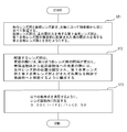
- the leading lens group and the succeeding lens group are arranged side by side in order from the object side along the optical axis (ST1).
- the subsequent lens group includes a first focusing lens group having a positive refractive power and a second focusing lens group having a negative refractive power arranged on the image plane side of the first focusing lens group.
- the lens group to be arranged is variable magnification, the distance between adjacent lens groups changes, and when focusing from an infinity object to a short-range object, the position of the preceding lens group is fixed, and the position of the preceding lens group is fixed.
- the 1st focusing lens group and the 2nd focusing lens group are configured to move toward the image plane side with different trajectories (ST2). Further, the lens group to be arranged is arranged in the lens barrel so as to satisfy the following conditional expression (ST3). 0.05 ⁇ (-fF2) / ft ⁇ 0.50 However, fF2: Focal length of the second focusing lens group ft: Focal length of the variable magnification optical system in the telephoto end state
- variable magnification optical system manufactured by the above procedure and the optical device equipped with the variable magnification optical system have two focusing lens groups, and are second when focusing from an infinity object to a short-range object. Focusing is performed with a clear division of roles, such as focusing the focusing lens group and correcting aberrations in the first focusing lens group. Therefore, curvature of field, spherical aberration, chromatic aberration, etc. Various aberrations can be satisfactorily corrected, and aberration fluctuations during focusing can be effectively suppressed.
- the leading lens group and the succeeding lens group are arranged in order from the object side along the optical axis (ST11).
- the leading lens group includes a first lens group having a positive refractive power and a second lens group having a negative refractive power arranged in order from the object side along the optical axis.
- the subsequent lens group includes a first focusing lens group having a positive refractive power and a second focusing lens group having a negative refractive power arranged on the image plane side of the first focusing lens group. To do.
- the lens group moves so that the first focusing lens group and the second focusing lens group move toward the image plane with different trajectories.
- variable magnification optical system manufactured by the above procedure and the optical device equipped with the variable magnification optical system have two focusing lens groups, and are second when focusing from an infinity object to a short-range object. Focusing is performed with a clear division of roles, such as focusing the focusing lens group and correcting aberrations in the first focusing lens group. Therefore, curvature of field, spherical aberration, chromatic aberration, etc. Various aberrations can be satisfactorily corrected, and aberration fluctuations during focusing can be effectively suppressed.
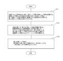
- the leading lens group and the succeeding lens group are arranged in order from the object side along the optical axis (ST21).
- the subsequent lens group includes a first focusing lens group having a positive refractive power and a second focusing lens group having a negative refractive power arranged on the image plane side of the first focusing lens group.
- the lens group is configured so that the second focusing lens group moves toward the image plane side with different trajectories (ST22).
- the second focusing lens group has one positive lens and one negative lens arranged in order from the object side (ST23).
- variable magnification optical system manufactured by the above procedure and the optical device equipped with the variable magnification optical system have two focusing lens groups, and are second when focusing from an infinity object to a short-range object. Focusing is performed with a clear division of roles, such as focusing the focusing lens group and correcting aberrations in the first focusing lens group. Therefore, curvature of field, spherical aberration, chromatic aberration, etc. Various aberrations can be satisfactorily corrected, and aberration fluctuations during focusing can be effectively suppressed.
- FIG. 4, FIG. 7 and FIG. 10 are diagrams showing the lens configuration and operation of the variable magnification optical system in each embodiment.
- the arrangement of the lens groups is shown by a cross-sectional view.
- the movement loci along the optical axis of the lens group G and the aperture S when zooming (magnifying) from the wide-angle end state (W) to the telephoto end state (T) are indicated by arrows.
- the moving direction of the focusing lens group when focusing from an infinity object to a close-range object is indicated by an arrow together with the letters "focus" and " ⁇ ".
- each lens group is represented by a combination of reference numerals G and numbers, and each lens is represented by a combination of reference numerals L and numbers.
- numbers are assigned to each embodiment. Therefore, the same combination of reference numerals and numbers may be used in a plurality of examples, but this does not mean that the configurations indicated by the combination of reference numerals and numbers are the same.
- FIG. 5, FIG. 8 and FIG. 11 are aberration diagrams of the variable magnification optical system at the time of focusing on an infinity object in each embodiment, in which (A) is a wide-angle end state and (B) is an intermediate focal length.
- the distance (C) indicates various aberrations in the telephoto end state.
- FIGS. 3, 6, 9 and 12 are aberration diagrams of the variable magnification optical system at the time of focusing on a close-range object in each embodiment, in which (A) is a wide-angle end state and (B) is.
- the intermediate focal length (C) indicates various aberrations in the telephoto end state.
- FNO indicates F number
- NA indicates numerical aperture
- Y indicates image height.
- the spherical aberration diagram shows the value of the F number or numerical aperture corresponding to the maximum aperture
- the astigmatism diagram and the distortion diagram show the maximum value of the image height
- the transverse aberration diagram shows the value of each image height.
- the solid line shows the sagittal image plane and the broken line shows the meridional image plane.
- the distortion diagram shows the distortion aberration based on the d-line
- the chromatic aberration of magnification diagram shows the chromatic aberration of magnification based on the g-line.
- f is the focal length of the entire lens system
- FNO is the F number
- 2 ⁇ is the angle of view (unit is ° (degrees)
- ⁇ is the half angle of view
- Y is the maximum image height.
- TL indicates the distance from the frontmost surface of the lens to the final surface of the lens on the optical axis when the infinity object is in focus, plus BF
- BF is the final surface of the lens on the optical axis when the infinity object is in focus.
- the air conversion distance (back focus) from to the image plane I is shown.
- the surface numbers indicate the order of the optical surfaces from the object side along the direction in which the light beam travels
- R is the radius of curvature of each optical surface (the surface whose center of curvature is located on the image surface side). Is a positive value)
- D is the distance on the optical axis from each optical surface to the next optical surface (or image surface)
- nd is the refractive index of the material of the optical member with respect to the d line
- ⁇ d is The Abbe number based on the d-line of the material of the optical member is shown.
- the surface spacing (Di) means that the distance from one surface i to the next surface is variable.
- S indicates an aperture diaphragm, and " ⁇ " of the radius of curvature indicates a plane or an aperture.
- the description of the refractive index of air nd 1.00000 is omitted.
- the table of [lens group data] shows the starting surface (the surface closest to the object) and the focal length of each lens group.
- the table of [variable spacing data] shows the surface spacing to the next surface at the surface number i in which the surface spacing is (Di) in the table showing [lens specifications].
- the left side shows the surface spacing when focusing on an infinite object, and the right side shows the surface spacing when focusing on a close-range object.
- the unit of length is set to "mm" in each table of the present specification. There is. However, the unit of length is not necessarily limited to "mm" because the variable magnification optical system can obtain the same optical performance even if it is proportionally enlarged or reduced.
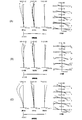
- FIG. 1 is a diagram showing a lens configuration of the variable magnification optical system ZL (1) according to the first embodiment.
- the variable magnification optical system ZL (1) has a first lens group G1 having a positive refractive power, a second lens group G2 having a negative refractive power, and a first lens group G2 having a positive refractive power arranged in order from the object side. It is composed of three lens groups G3, an aperture S, a fourth lens group G4 having a positive refractive power, a fifth lens group G5 having a negative refractive power, and a sixth lens group having a positive refractive power. ing.
- the image plane I is located after the sixth lens group G6.
- the fourth lens group to the sixth lens group have a triplet structure of unevenness and convexity, which makes it easy to suppress aberration fluctuations during magnification change.
- the fourth lens group G4 functions as the first focusing lens group F1
- the fifth lens group G5 functions as the second focusing lens group F2.
- the second focusing lens group also functions as a teleconverter that expands the focal length of the first to fourth lens groups.
- the first lens group G1, the third lens group G3, the fourth lens group G4, the fifth lens group G5, and the sixth lens group G6 are used when the magnification is changed from the wide-angle end state (W) to the telephoto end state (T). In addition, it moves along the locus indicated by the arrow in the lower part of FIG. As a result, the distance between adjacent lens groups changes, and the shooting magnification is changed (magnification is performed).
- the second lens group G2 is fixed and does not move when the magnification is changed.
- the fourth lens group G4 and the fifth lens group G5 move to the image plane side in different trajectories as shown by the arrows in the upper part of FIG.
- the first lens group G1 is composed of a negative meniscus lens L11 having a convex surface facing the object side, a positive meniscus lens L12 having a convex surface facing the object side, and a biconvex positive lens L13.
- the second lens group G2 is composed of a biconcave negative lens L21, a biconvex positive lens L22, a biconcave negative lens L23, and a biconcave negative lens L24.
- the third lens group G3 includes a biconvex positive lens L31, a negative meniscus lens L32 with a convex surface facing the object side, a biconvex positive lens L33, and a biconvex positive lens L34. It is composed of a bonded positive lens with a biconcave negative lens L35.
- the fourth lens group G4 is composed of a biconvex positive lens L41, a negative meniscus lens L42 with a convex surface facing the object side, and a positive meniscus lens L43 with a convex surface facing the object side.
- the fifth lens group G5 is composed of a positive meniscus lens L51 with a concave surface facing the object side and a negative lens L52 having a biconcave shape.
- the sixth lens group G6 is composed of a positive meniscus lens L61 with a concave surface facing the object side and a negative meniscus lens L62 with a concave surface facing the object side. Further, a parallel flat plate PP is arranged in front of the image plane I.
- Table 1 lists the values of the specifications of the variable magnification optical system according to the first embodiment.
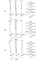
- FIG. 2 shows various aberration values of the variable magnification optical system according to the first embodiment in the infinity object in-focus state
- FIG. 3 shows various aberration values of the variable-magnification optical system according to the first embodiment in the close-range object in-focus state.
- A shows various aberration values in the wide-angle end state
- B shows various aberration values in the intermediate focal length
- C shows various aberration values in the telephoto end state. From each aberration diagram, the variable magnification optical system according to the first embodiment satisfactorily corrects various aberrations when focusing from an infinity object to a short-distance object in the entire range from the wide-angle end state to the telephoto end state. It can be seen that aberration fluctuations can be effectively suppressed.
- FIG. 4 is a diagram showing a lens configuration of the variable magnification optical system ZL (2) according to the second embodiment.
- the variable magnification optical system ZL (2) has a first lens group G1 having a positive refractive power, a second lens group G2 having a negative refractive power, and a first lens group G2 having a positive refractive power arranged in order from the object side. It is composed of three lens groups G3, an aperture S, a fourth lens group G4 having a positive refractive power, a fifth lens group G5 having a negative refractive power, and a sixth lens group having a positive refractive power. ing.
- the image plane I is located after the sixth lens group G6.
- the fourth lens group to the sixth lens group have a triplet structure of unevenness and convexity, which makes it easy to suppress aberration fluctuations during magnification change.
- the fourth lens group G4 functions as the first focusing lens group F1
- the fifth lens group G5 functions as the second focusing lens group F2.
- the second focusing lens group also functions as a teleconverter that expands the focal length of the first to fourth lens groups.
- the first lens group G1, the third lens group G3, the fourth lens group G4, the fifth lens group G5, and the sixth lens group G6 shift from the wide-angle end state (W) to the telephoto end state (T). , It moves along the locus indicated by the arrow in the lower part of FIG. As a result, the distance between adjacent lens groups changes, and the shooting magnification is changed (magnification is performed).
- the second lens group G2 is fixed and does not move when the magnification is changed.
- the fourth lens group G4 and the fifth lens group G5 move to the image plane side in different trajectories as shown by the arrows in the upper part of FIG.
- the first lens group G1 is composed of a negative meniscus lens L11 having a convex surface facing the object side and a positive meniscus lens L12 having a convex surface facing the object side, and a positive meniscus lens L13 having a convex surface facing the object side. It is composed.
- the second lens group G2 is composed of a negative meniscus lens L21 having a convex surface facing the object side, a biconvex positive lens L22, a biconcave negative lens L23, and a biconcave negative lens L24. ..
- the third lens group G3 includes a biconvex positive lens L31, a negative meniscus lens L32 with a convex surface facing the object side, a biconvex positive lens L33, and a biconvex positive lens L34. It is composed of a bonded positive lens with a biconcave negative lens L35.
- the fourth lens group G4 is composed of a biconvex positive lens L41, a negative meniscus lens L42 with a convex surface facing the object side, and a biconvex positive lens L43.
- the fifth lens group G5 is composed of a positive meniscus lens L51 with a concave surface facing the object side and a negative lens L52 having a biconcave shape.
- the sixth lens group G6 is composed of a positive meniscus lens L61 with a concave surface facing the object side and a negative meniscus lens L62 with a concave surface facing the object side. Further, a parallel flat plate PP is arranged in front of the image plane I.
- Table 2 lists the values of the specifications of the variable magnification optical system according to the second embodiment.
- Surface number RD nd ⁇ d Object surface ⁇ 1 164.2107 1.00 1.7950 28.69 2 81.6916 5.44 1.5932 67.90 3 541.7710 0.10 4 64.6180 6.69 1.4970 81.61 5 1556.5885 (D5) 6 372.6279 1.00 1.7200 46.02 7 31.3950 0.58 8 32.1189 8.32 1.7847 25.64 9 -93.6053 0.11 10 -119.9230 1.00 1.7725 49.62 11 44.7568 5.56 12 -37.2692 1.00 1.8061
- FIG. 5 shows various aberration values of the variable magnification optical system according to the second embodiment in the infinity object in-focus state
- FIG. 6 shows various aberration values of the variable-magnification optical system according to the second embodiment in the close-range object in-focus state.
- A shows various aberration values in the wide-angle end state
- B shows various aberration values in the intermediate focal length
- C shows various aberration values in the telephoto end state. From each aberration diagram, the variable magnification optical system according to the second embodiment satisfactorily corrects various aberrations when focusing from an infinity object to a short-distance object in the entire range from the wide-angle end state to the telephoto end state. It can be seen that aberration fluctuations can be effectively suppressed.
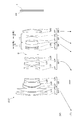
- FIG. 7 is a diagram showing a lens configuration of the variable magnification optical system ZL (3) according to the third embodiment.
- the variable magnification optical system ZL (3) has a first lens group G1 having a positive refractive power, a second lens group G2 having a negative refractive power, and a first lens group G2 having a positive refractive power arranged in order from the object side.
- the three lens group G3, the fourth lens group G4 having a positive refractive power, the aperture S, the fifth lens group G5 having a positive refractive power, the sixth lens group having a negative refractive power, and the positive It is composed of a seventh lens group G7 having a refractive power and an eighth lens group G8 having a negative refractive power.
- the image plane I is located after the eighth lens group G8.
- the 5th to 7th lens groups have a triplet structure with unevenness, which makes it easy to suppress aberration fluctuations during scaling. Further, since the eighth lens group having a negative refractive power is arranged behind the seventh lens group, the structure is close to the telephoto structure as a whole, and the back focus and the effect of shortening the total length of the optical system can be easily obtained.
- the fifth lens group G5 functions as the first focusing lens group F1
- the sixth lens group G6 functions as the second focusing lens group F2.
- the second focusing lens group also functions as a teleconverter that expands the focal length of the first to fifth lens groups.
- the second lens group G2, the third lens group G3, the fifth lens group G5, the sixth lens group G6, and the eighth lens group G8 are used when the magnification is changed from the wide-angle end state (W) to the telephoto end state (T). In addition, it moves along the locus indicated by the arrow in the lower part of FIG. As a result, the distance between adjacent lens groups changes, and the shooting magnification is changed (magnification is performed).
- the first lens group G1, the fourth lens group G5, and the seventh lens group G7 are fixed and do not move during scaling. When focusing from an infinity object to a short-range object, the fifth lens group G5 and the sixth lens group G6 move to the image plane side in different trajectories as shown by the arrows in the upper part of FIG.
- the first lens group G1 is composed of a negative meniscus lens L11 having a convex surface facing the object side, a bonded positive lens L12 having a biconvex positive lens L12, and a positive meniscus lens L13 having a convex surface facing the object side.
- the second lens group G2 includes a negative meniscus lens L21 having a convex surface facing the object side, a negative lens L22 having a biconcave shape and a positive lens L23 having a biconvex shape, and a negative lens L24 having a biconcave shape. Consists of.
- the third lens group G3 is composed of a positive meniscus lens L31 with a concave surface facing the object side.
- the fourth lens group G4 is composed of a biconvex positive lens L41, a biconvex positive lens L42, and a biconcave negative lens L43.
- the fifth lens group G5 is composed of a negative meniscus lens L51 with a convex surface facing the object side and a biconvex positive lens L52.
- the sixth lens group G6 is composed of a junction negative lens of a biconvex positive lens L61 and a biconcave negative lens L62.
- the seventh lens group G7 is composed of a negative meniscus lens L71 with a convex surface facing the object side and a biconvex positive lens L72.
- the eighth lens group G8 is composed of a biconcave negative lens L81. Further, a parallel flat plate PP is arranged in front of the image plane I.
- Table 3 lists the values of the specifications of the variable magnification optical system according to the third embodiment.
- FIG. 8 shows various aberration values of the variable magnification optical system according to the third embodiment in the infinity object in-focus state
- FIG. 9 shows various aberration values of the variable-magnification optical system according to the third embodiment in the close-range object in-focus state.
- A shows various aberration values in the wide-angle end state
- B shows various aberration values in the intermediate focal length
- C shows various aberration values in the telephoto end state. From each aberration diagram, the variable magnification optical system according to the third embodiment satisfactorily corrects various aberrations when focusing from an infinity object to a short-distance object in the entire range from the wide-angle end state to the telephoto end state. It can be seen that aberration fluctuations can be effectively suppressed.
- FIG. 10 is a diagram showing a lens configuration of the variable magnification optical system ZL (4) according to the fourth embodiment.
- the variable magnification optical system ZL (4) has a first lens group G1 having a positive refractive power, a second lens group G2 having a negative refractive power, and a first lens group G2 having a positive refractive power arranged in order from the object side.
- It is composed of a sixth lens group having a positive refractive power, a seventh lens group G7 having a positive refractive power, and an eighth lens group having a negative refractive power.
- the image plane I is located after the eighth lens group G8.
- the 5th to 7th lens groups have a triplet structure with unevenness, which makes it easy to suppress aberration fluctuations during scaling. Further, since the eighth lens group having a negative refractive power is arranged behind the seventh lens group, the structure is close to the telephoto structure as a whole, and the back focus and the effect of shortening the total length of the optical system can be easily obtained.
- the fifth lens group G5 functions as the first focusing lens group F1
- the sixth lens group G6 functions as the second focusing lens group F2.
- the second focusing lens group also functions as a teleconverter that expands the focal length of the first to fifth lens groups.
- the first lens group G1, the second lens group G2, the fourth lens group G4, the fifth lens group G5, the sixth lens group G6, and the eighth lens group G8 are in the wide-angle end state (W) to the telephoto end state (T).
- W wide-angle end state
- T telephoto end state
- the lens moves along the trajectory indicated by the arrow in the lower part of FIG.
- the second lens group G2 is fixed and does not move when the magnification is changed.
- the fifth lens group G5 and the sixth lens group G6 move to the image plane side in different trajectories as shown by the arrows in the upper part of FIG.
- the first lens group G1 is composed of a positive meniscus lens L11 having a convex surface facing the object side, a negative meniscus lens L12 having a convex surface facing the object side, and a positive meniscus lens L13 having a convex surface facing the object side. It is composed.
- the second lens group G2 includes a negative meniscus lens L21 having a convex surface facing the object side, a negative meniscus lens L22 having a convex surface facing the object side, and a positive meniscus lens L23 having a convex surface facing the object side. It is composed of a biconcave negative lens L24.
- the third lens group G3 is composed of a biconvex positive lens L31.
- the fourth lens group G4 is composed of a biconvex positive lens L41, a biconvex positive lens L42, and a biconcave negative lens L43.
- the fifth lens group G5 is composed of a positive meniscus lens L51 with a concave surface facing the object side, an aperture diaphragm S, and a biconvex positive lens L52.
- the sixth lens group G6 is composed of a junction negative lens of a positive meniscus lens L61 with a concave surface facing the object side and a negative lens L62 having a biconcave shape.
- the seventh lens group G7 is composed of a negative meniscus lens L71 with a convex surface facing the object side and a biconvex positive lens L72.
- the eighth lens group G8 is composed of a biconcave negative lens L81. Further, a parallel flat plate PP is arranged in front of the image plane I.
- Table 4 lists the values of the specifications of the variable magnification optical system according to the fourth embodiment.
- FIG. 11 shows various aberration values of the variable magnification optical system according to the fourth embodiment in the infinity object in-focus state
- FIG. 12 shows various aberration values of the variable-magnification optical system according to the fourth embodiment in the close-range object in-focus state.
- A shows various aberration values in the wide-angle end state
- B shows various aberration values in the intermediate focal length
- C shows various aberration values in the telephoto end state. From each aberration diagram, the variable magnification optical system according to the fourth embodiment satisfactorily corrects various aberrations when focusing from an infinity object to a short-distance object in the entire range from the wide-angle end state to the telephoto end state. It can be seen that aberration fluctuations can be effectively suppressed.
- Example 1 Example 2 Example 3
- Example 4 (1) 0.213 0.192 0.243 0.207 (2) 26.520 23.780 25.640 25.640 (3) 1.006 0.960 1.036 0.977 (4) 0.136 0.222 0.155 0.121 (5) 0.163 0.124 0.089 0.050 (6) 0.618 0.665 1.432 2.140 (7) 0.648 0.591 0.626 0.624 (8) 0.418 0.374 0.381 0.372 (9) 0.391 0.331 0.233 0.135 (10) 0.127 0.108 0.111 0.107 (11) 0.115 0.089 0.049 0.018 (12) 26.520 23.780 25.640 25.640 (13) 0.084 0.079 0.095 0.084 (14) 0.711 0.664 0.368 0.358
- the present invention is not limited to the above embodiment, and can be appropriately modified as long as the optical performance specified by the description of each claim is not impaired.
- variable magnification optical system having other group configurations (for example, a lens or a lens or an image plane side of the variable magnification optical system on the most object side or the most image plane side) It is also possible to have a configuration in which a lens group is added, etc.).
- the lens group refers to a portion having at least one lens separated by an air interval that changes at the time of magnification change or focusing.
- the aperture diaphragm is arranged in the third lens group, the fourth lens group, or the fifth lens group in each of the above embodiments, the aperture diaphragm is not provided as the aperture diaphragm, and the lens frame is used. A form in which the role is substituted is conceivable.
- the lens surface may be spherical, flat or aspherical.
- the spherical or flat lens surface facilitates lens processing and assembly adjustment, can prevent deterioration of optical performance due to errors in lens processing and assembly adjustment, and further deteriorates depiction performance even if the image surface shifts. It has the advantage of being less.
- the aspherical lens surface may be an aspherical surface obtained by grinding, a glass-molded aspherical surface obtained by molding glass into an aspherical shape, or a composite aspherical surface formed by forming a resin provided on the glass surface into an aspherical shape. Good.
- the lens surface may be a diffraction surface, and the lens may be a refractive index distribution type lens (GRIN lens) or a plastic lens.
- GRIN lens refractive index distribution type lens
- An antireflection film having a high transmittance in a wide wavelength range may be applied to each lens surface in order to reduce flare and ghost and achieve high contrast optical performance.
- G1 1st lens group G2 2nd lens group G3 3rd lens group G4 4th lens group G5 5th lens group G6 6th lens group G7 7th lens group G8 8th lens group I Image plane S Aperture aperture
Landscapes
- Physics & Mathematics (AREA)
- General Physics & Mathematics (AREA)
- Optics & Photonics (AREA)
- Nonlinear Science (AREA)
- Lenses (AREA)
Priority Applications (3)
| Application Number | Priority Date | Filing Date | Title |
|---|---|---|---|
| CN202080060100.7A CN114375413B (zh) | 2019-08-29 | 2020-08-24 | 变倍光学系统及光学设备 |
| JP2021542876A JP7243841B2 (ja) | 2019-08-29 | 2020-08-24 | 変倍光学系および光学機器 |
| US17/638,803 US20220291490A1 (en) | 2019-08-29 | 2020-08-24 | Zoom optical system, optical apparatus and method for manufacturing the zoom optical system |
Applications Claiming Priority (4)
| Application Number | Priority Date | Filing Date | Title |
|---|---|---|---|
| JP2019157409 | 2019-08-29 | ||
| JP2019-157408 | 2019-08-29 | ||
| JP2019157408 | 2019-08-29 | ||
| JP2019-157409 | 2019-08-29 |
Publications (1)
| Publication Number | Publication Date |
|---|---|
| WO2021039697A1 true WO2021039697A1 (ja) | 2021-03-04 |
Family
ID=74685566
Family Applications (1)
| Application Number | Title | Priority Date | Filing Date |
|---|---|---|---|
| PCT/JP2020/031788 WO2021039697A1 (ja) | 2019-08-29 | 2020-08-24 | 変倍光学系、光学機器および変倍光学系の製造方法 |
Country Status (4)
| Country | Link |
|---|---|
| US (1) | US20220291490A1 (zh) |
| JP (1) | JP7243841B2 (zh) |
| CN (1) | CN114375413B (zh) |
| WO (1) | WO2021039697A1 (zh) |
Citations (5)
| Publication number | Priority date | Publication date | Assignee | Title |
|---|---|---|---|---|
| JPH03225308A (ja) * | 1990-01-31 | 1991-10-04 | Canon Inc | リアーフォーカスズームレンズ |
| JP2014102462A (ja) * | 2012-11-22 | 2014-06-05 | Canon Inc | ズームレンズ及びそれを有する撮像装置 |
| JP2015197593A (ja) * | 2014-04-01 | 2015-11-09 | キヤノン株式会社 | ズームレンズ及びそれを有する撮像装置 |
| JP2017219643A (ja) * | 2016-06-07 | 2017-12-14 | キヤノン株式会社 | ズームレンズ |
| WO2018139160A1 (ja) * | 2017-01-25 | 2018-08-02 | ソニー株式会社 | ズームレンズおよび撮像装置 |
Family Cites Families (4)
| Publication number | Priority date | Publication date | Assignee | Title |
|---|---|---|---|---|
| JP5885026B2 (ja) * | 2012-02-29 | 2016-03-15 | 株式会社ニコン | 変倍光学系、この変倍光学系を有する光学機器、及び、変倍光学系の製造方法 |
| CN106796339B (zh) * | 2014-08-29 | 2020-07-21 | 株式会社尼康 | 变倍光学系统及光学设备 |
| US10877240B2 (en) * | 2015-11-30 | 2020-12-29 | Nikon Corporation | Zoom optical system, optical apparatus and method for manufacturing the zoom optical system |
| CN113589500B (zh) * | 2016-11-21 | 2023-04-07 | 株式会社尼康 | 变倍光学系统以及光学设备 |
-
2020
- 2020-08-24 CN CN202080060100.7A patent/CN114375413B/zh active Active
- 2020-08-24 WO PCT/JP2020/031788 patent/WO2021039697A1/ja active Application Filing
- 2020-08-24 JP JP2021542876A patent/JP7243841B2/ja active Active
- 2020-08-24 US US17/638,803 patent/US20220291490A1/en active Pending
Patent Citations (5)
| Publication number | Priority date | Publication date | Assignee | Title |
|---|---|---|---|---|
| JPH03225308A (ja) * | 1990-01-31 | 1991-10-04 | Canon Inc | リアーフォーカスズームレンズ |
| JP2014102462A (ja) * | 2012-11-22 | 2014-06-05 | Canon Inc | ズームレンズ及びそれを有する撮像装置 |
| JP2015197593A (ja) * | 2014-04-01 | 2015-11-09 | キヤノン株式会社 | ズームレンズ及びそれを有する撮像装置 |
| JP2017219643A (ja) * | 2016-06-07 | 2017-12-14 | キヤノン株式会社 | ズームレンズ |
| WO2018139160A1 (ja) * | 2017-01-25 | 2018-08-02 | ソニー株式会社 | ズームレンズおよび撮像装置 |
Also Published As
| Publication number | Publication date |
|---|---|
| CN114375413A (zh) | 2022-04-19 |
| US20220291490A1 (en) | 2022-09-15 |
| JP7243841B2 (ja) | 2023-03-22 |
| JPWO2021039697A1 (zh) | 2021-03-04 |
| CN114375413B (zh) | 2023-12-26 |
Similar Documents
| Publication | Publication Date | Title |
|---|---|---|
| JP5130806B2 (ja) | 変倍光学系、撮像装置、変倍光学系の変倍方法 | |
| JP5168641B2 (ja) | 変倍光学系、これを有する光学機器及び変倍方法 | |
| JP5581730B2 (ja) | 変倍光学系、光学装置 | |
| US11598940B2 (en) | Variable magnification optical system, optical apparatus, and method for producing variable magnification optical system | |
| JP5135723B2 (ja) | 防振機能を有するズームレンズ、撮像装置、ズームレンズの防振方法、ズームレンズの変倍方法 | |
| EP2360504A1 (en) | Zoom lens system, optical apparatus and method for manufacturing zoom lens system | |
| CN107430261B (zh) | 变倍光学系统以及光学设备 | |
| WO2019097669A1 (ja) | 変倍光学系、光学装置、変倍光学系の製造方法 | |
| JP7021683B2 (ja) | ズームレンズおよび光学機器 | |
| JP6721859B2 (ja) | 光学系及び光学機器 | |
| CN111527437B (zh) | 变倍光学系统以及光学装置 | |
| JP6787485B2 (ja) | 変倍光学系、光学装置、および変倍光学系の製造方法 | |
| WO2020250672A1 (ja) | 変倍光学系、光学機器および変倍光学系の製造方法 | |
| JP6784952B2 (ja) | 光学系及び光学機器 | |
| JP2023060137A (ja) | 光学系、光学機器、および光学系の製造方法 | |
| WO2013111539A1 (ja) | ズームレンズ、光学機器及びズームレンズの製造方法 | |
| CN113366362B (zh) | 变倍光学系统以及光学设备 | |
| JP4955875B2 (ja) | ズームレンズ及びそれを有する光学機器 | |
| WO2021039697A1 (ja) | 変倍光学系、光学機器および変倍光学系の製造方法 | |
| JP6784950B2 (ja) | 光学系及び光学機器 | |
| JP7439839B2 (ja) | 変倍光学系および光学機器 | |
| WO2024034309A1 (ja) | 変倍光学系、光学機器、および変倍光学系の製造方法 | |
| JP2015102690A (ja) | ズームレンズ、光学機器及びズームレンズの製造方法 | |
| JPWO2019229817A1 (ja) | 光学系、光学機器、および光学系の製造方法 | |
| CN114286960B (zh) | 变倍光学系统及光学设备 |
Legal Events
| Date | Code | Title | Description |
|---|---|---|---|
| 121 | Ep: the epo has been informed by wipo that ep was designated in this application |
Ref document number: 20857097 Country of ref document: EP Kind code of ref document: A1 |
|
| ENP | Entry into the national phase |
Ref document number: 2021542876 Country of ref document: JP Kind code of ref document: A |
|
| NENP | Non-entry into the national phase |
Ref country code: DE |
|
| 122 | Ep: pct application non-entry in european phase |
Ref document number: 20857097 Country of ref document: EP Kind code of ref document: A1 |