WO2021039697A1 - Variable magnification optical system, optical device, and method for manufacturing variable magnification optical system - Google Patents
Variable magnification optical system, optical device, and method for manufacturing variable magnification optical system Download PDFInfo
- Publication number
- WO2021039697A1 WO2021039697A1 PCT/JP2020/031788 JP2020031788W WO2021039697A1 WO 2021039697 A1 WO2021039697 A1 WO 2021039697A1 JP 2020031788 W JP2020031788 W JP 2020031788W WO 2021039697 A1 WO2021039697 A1 WO 2021039697A1
- Authority
- WO
- WIPO (PCT)
- Prior art keywords
- lens group
- focusing
- optical system
- focusing lens
- variable magnification
- Prior art date
Links
Images


Classifications
-
- G—PHYSICS
- G02—OPTICS
- G02B—OPTICAL ELEMENTS, SYSTEMS OR APPARATUS
- G02B15/00—Optical objectives with means for varying the magnification
- G02B15/14—Optical objectives with means for varying the magnification by axial movement of one or more lenses or groups of lenses relative to the image plane for continuously varying the equivalent focal length of the objective
- G02B15/146—Optical objectives with means for varying the magnification by axial movement of one or more lenses or groups of lenses relative to the image plane for continuously varying the equivalent focal length of the objective having more than five groups
- G02B15/1461—Optical objectives with means for varying the magnification by axial movement of one or more lenses or groups of lenses relative to the image plane for continuously varying the equivalent focal length of the objective having more than five groups the first group being positive
-
- G—PHYSICS
- G02—OPTICS
- G02B—OPTICAL ELEMENTS, SYSTEMS OR APPARATUS
- G02B15/00—Optical objectives with means for varying the magnification
- G02B15/14—Optical objectives with means for varying the magnification by axial movement of one or more lenses or groups of lenses relative to the image plane for continuously varying the equivalent focal length of the objective
- G02B15/142—Optical objectives with means for varying the magnification by axial movement of one or more lenses or groups of lenses relative to the image plane for continuously varying the equivalent focal length of the objective having two groups only
- G02B15/1421—Optical objectives with means for varying the magnification by axial movement of one or more lenses or groups of lenses relative to the image plane for continuously varying the equivalent focal length of the objective having two groups only the first group being positive
-
- G—PHYSICS
- G02—OPTICS
- G02B—OPTICAL ELEMENTS, SYSTEMS OR APPARATUS
- G02B15/00—Optical objectives with means for varying the magnification
- G02B15/14—Optical objectives with means for varying the magnification by axial movement of one or more lenses or groups of lenses relative to the image plane for continuously varying the equivalent focal length of the objective
- G02B15/16—Optical objectives with means for varying the magnification by axial movement of one or more lenses or groups of lenses relative to the image plane for continuously varying the equivalent focal length of the objective with interdependent non-linearly related movements between one lens or lens group, and another lens or lens group
-
- G—PHYSICS
- G02—OPTICS
- G02B—OPTICAL ELEMENTS, SYSTEMS OR APPARATUS
- G02B27/00—Optical systems or apparatus not provided for by any of the groups G02B1/00 - G02B26/00, G02B30/00
- G02B27/0012—Optical design, e.g. procedures, algorithms, optimisation routines
-
- G—PHYSICS
- G02—OPTICS
- G02B—OPTICAL ELEMENTS, SYSTEMS OR APPARATUS
- G02B15/00—Optical objectives with means for varying the magnification
- G02B15/14—Optical objectives with means for varying the magnification by axial movement of one or more lenses or groups of lenses relative to the image plane for continuously varying the equivalent focal length of the objective
- G02B15/16—Optical objectives with means for varying the magnification by axial movement of one or more lenses or groups of lenses relative to the image plane for continuously varying the equivalent focal length of the objective with interdependent non-linearly related movements between one lens or lens group, and another lens or lens group
- G02B15/20—Optical objectives with means for varying the magnification by axial movement of one or more lenses or groups of lenses relative to the image plane for continuously varying the equivalent focal length of the objective with interdependent non-linearly related movements between one lens or lens group, and another lens or lens group having an additional movable lens or lens group for varying the objective focal length
Definitions
- the present invention relates to a variable magnification optical system, an optical instrument, and a method for manufacturing the variable magnification optical system.
- a zoom lens suitable for photographic cameras, electronic still cameras, video cameras, etc.
- a zoom lens has been proposed in which a part of a lens group (rear group) arranged near the image plane is moved to focus.
- a zoom lens it is required to suppress various aberrations such as curvature of field and realize good optical performance at the time of focusing.
- the first variable magnification optical system includes a preceding lens group and a succeeding lens group arranged in order from the object side along the optical axis, and the succeeding lens group is a first focusing lens having a positive refractive power.
- the group and a second focusing lens group having a negative refractive power arranged on the image plane side of the first focusing lens group are included.
- the second focusing lens group moves to the image plane side with different trajectories, and satisfies the following conditional expression.
- fF2 Focal length of the second focusing lens group
- ft Focal length of the variable magnification optical system in the telephoto end state
- the second variable magnification optical system comprises a preceding lens group and a succeeding lens group arranged in order from the object side along the optical axis, and the preceding lens group is sequentially arranged from the object side along the optical axis.
- the following lens group includes a first lens group having a positive refractive force and a second lens group having a negative refractive force
- the subsequent lens group includes a first focusing lens group having a positive refractive force and the above-mentioned Includes a second focusing lens group having a negative refractive force arranged on the image plane side of the first focusing lens group, and adjacent lenses when scaling from the wide-angle end state to the telephoto end state.
- the first focusing lens group and the second focusing lens group move toward the object side with different trajectories, and when focusing from an infinity object to a short-range object, The first focusing lens group and the second focusing lens group move to the image plane side with different trajectories.
- the third variable magnification optical system consists of a preceding lens group and a succeeding lens group arranged in order from the object side along the optical axis, and the succeeding lens group is a first focusing having a positive refractive power. It includes a lens group and a second focusing lens group having a negative refractive power arranged on the image plane side of the first focusing lens group.
- the second focusing lens group moves to the image plane side with different trajectories.
- the second focusing lens group includes one positive lens and one negative lens arranged in order from the object side.
- the optical device according to the present invention is configured to include the above variable magnification optical system.
- each lens group is configured and arranged in a lens barrel as follows.
- the variable magnification optical system consists of a leading lens group and a trailing lens group arranged in order from the object side along the optical axis, and the trailing lens group includes a first focusing lens group having a positive refractive power and a first focusing lens group. It includes a second focusing lens group having a negative refractive power arranged on the image plane side of the lens group.
- the second focusing lens group moves to the image plane side with different trajectories, and satisfies the following conditional expression. 0.05 ⁇ (-fF2) / ft ⁇ 0.50
- fF2 Focal length of the second focusing lens group
- ft Focal length of the variable magnification optical system in the telephoto end state
- the second method for manufacturing a variable magnification optical system is as follows, in which each lens group is configured and arranged in a lens barrel.
- the leading lens group and the succeeding lens group are arranged in order from the object side along the optical axis.
- the leading lens group includes a first lens group having a positive refractive power and a second lens group having a negative refractive power arranged in order from the object side along the optical axis.
- the subsequent lens group includes a first focusing lens group having a positive refractive power and a second focusing lens group having a negative refractive power arranged on the image plane side of the first focusing lens group. To do.
- the lens group moves so that the first focusing lens group and the second focusing lens group move toward the image plane with different trajectories.
- the third method for manufacturing a variable magnification optical system is as follows, in which each lens group is configured and arranged in a lens barrel.
- the leading lens group and the succeeding lens group are arranged in order from the object side along the optical axis.
- the subsequent lens group includes a first focusing lens group having a positive refractive power and a second focusing lens group having a negative refractive power arranged on the image plane side of the first focusing lens group.
- the lens group is configured so that the second focusing lens group moves toward the image plane side with different trajectories.
- the second focusing lens group has one positive lens and one negative lens arranged in order from the object side.
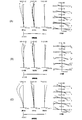
- FIG. It is a diagram of various aberrations at the time of focusing an object at infinity of the variable magnification optical system according to the first embodiment, (A) is an aberration value in a wide-angle end state, (B) is an aberration value in an intermediate focal length, and (C). Indicates various aberration values in the telephoto end state. It is a diagram of various aberrations at the time of focusing on a close-range object of the variable magnification optical system according to the first embodiment, (A) is an aberration value in a wide-angle end state, (B) is an aberration value in an intermediate focal length, and (C).
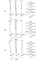
- FIG. It is a diagram of various aberrations at the time of focusing on a close-range object of the variable magnification optical system according to the second embodiment, ((A) is various aberration values in the wide-angle end state, (B) is various aberration values in the intermediate focal length, (C). ) Indicates various aberration values in the telephoto end state. It is a figure which shows the lens structure of the variable magnification optical system which concerns on Example 3.
- FIG. It is a diagram of various aberrations at the time of focusing an object at infinity of the variable magnification optical system according to the third embodiment, (A) is an aberration value in a wide-angle end state, (B) is an aberration value in an intermediate focal length, (C).
- (A) is an aberration value in a wide-angle end state
- (B) is an aberration value in an intermediate focal length
- (C). Indicates various aberration values in the telephoto end state.
- (A) is an aberration value in a wide-angle end state
- (B) is an aberration value in an intermediate focal length
- (C) Indicates various aberration values in the telephoto end state.
- FIG. 13 shows a schematic configuration of a digital camera, which is an embodiment of an optical device.
- the digital camera 1 is composed of a main body 2 and a photographing lens 3 that can be attached to and detached from the main body 2.
- the main body 2 includes an image sensor 4, a main body control unit (not shown) that controls the operation of a digital camera, and a liquid crystal operation screen 5.
- the photographing lens 3 includes a variable magnification optical system ZL composed of a plurality of lens groups and a lens position control mechanism (not shown) for controlling the position of each lens group.
- the lens position control mechanism is composed of a sensor that detects the position of the lens group, a motor that moves the lens group back and forth along the optical axis, a control circuit that drives the motor, and the like.
- variable magnification optical system ZL of the photographing lens 3 The light from the subject is collected by the variable magnification optical system ZL of the photographing lens 3 and reaches the image plane I of the image sensor 4.
- the light from the subject that has reached the image plane I is photoelectrically converted by the image sensor 4 and recorded as digital image data in a memory (not shown).
- the digital image data recorded in the memory is displayed on the liquid crystal screen 5 according to the user's operation.
- the variable magnification optical system ZL will be described in detail.
- the variable magnification optical system of the first embodiment consists of a preceding lens group and a succeeding lens group arranged in order from the object side along the optical axis, and the succeeding lens group includes a first focusing lens group having a positive refractive power. , Includes a second focusing lens group having a negative refractive power arranged on the image plane side of the first focusing lens group.
- the distance between adjacent lens groups changes, and at the time of focusing from an infinity object to a short-range object, the position of the preceding lens group is fixed, and it becomes the first focusing lens group.
- the second focusing lens group moves to the image plane side with different trajectories, and satisfies the following conditional equation (1).
- fF2 Focal length of the second focusing lens group
- ft Focal length of the variable magnification optical system in the telephoto end state
- Conditional expression (1) defines the ratio between the focal length of the second focusing lens group and the focal length of the variable magnification optical system in the telephoto end state, and determines the appropriate range of power of the second focusing lens group. Shown.
- various aberrations such as curvature of field, spherical aberration, and chromatic aberration can be satisfactorily corrected when focusing from an infinity object to a close-range object, and aberration fluctuations can be effectively suppressed. it can.
- the upper limit of the conditional expression (1) is a smaller value, for example, 0.45, 0.40, 0.38, 0.35, 0.33, It is preferably 0.30, 0.28, or 0.25.
- the lower limit of the conditional expression (1) is set to a larger value, for example, 0.08, 0.10, 0.13, 0.15, or 0,18. Is preferable.
- variable magnification optical system of the first embodiment can satisfactorily correct various aberrations over the entire range from the wide-angle end state to the telephoto end state by satisfying the above conditional expression with the above configuration, and can focus at a short distance. High optical performance can be achieved at times.
- variable magnification optical system of the second embodiment consists of a leading lens group and a succeeding lens group arranged in order from the object side along the optical axis, and the leading lens group is arranged in order from the object side along the optical axis.
- a first lens group having a positive refractive power and a second lens group having a negative refractive power are included, and subsequent lens groups include a first focusing lens group having a positive refractive power and a first focusing lens. It includes a second focusing lens group having a negative refractive force arranged on the image plane side of the group.
- the distance between adjacent lens groups changes, and the first in-focus lens group and the second in-focus lens group move toward the object with different trajectories.
- the first focusing lens group and the second focusing lens group move to the image plane side with different trajectories.
- variable magnification optical system of the second embodiment can satisfactorily correct various aberrations over the entire range from the wide-angle end state to the telephoto end state, and realizes high optical performance even during short-distance focusing. can do.
- the variable magnification optical system of the third embodiment consists of a preceding lens group and a succeeding lens group arranged in order from the object side along the optical axis, and the succeeding lens group is a first focusing lens group having a positive refractive power. And a second focusing lens group having a negative refractive power arranged on the image plane side of the first focusing lens group.
- the second focusing lens group moves to the image plane side with different trajectories.
- the second focusing lens group includes one positive lens and one negative lens arranged in order from the object side.
- variable magnification optical system of the third embodiment focusing is mainly performed by the movement of the second focusing lens group, and the aberration fluctuating due to the movement of the second focusing lens group is corrected by the first focusing lens group.
- the lens In a variable magnification optical system having such a configuration, if the second focusing lens group is composed of one lens, it becomes difficult to satisfactorily correct various aberrations, and as the number of lenses increases, the focusing lens group becomes heavy. It becomes difficult to realize high-speed focusing. On the other hand, when the second focusing lens group has one positive lens and one negative lens, fluctuations in various aberrations such as chromatic aberration can be suppressed even if the lens group is moved significantly. It is possible to realize high-speed focusing by reducing the size and weight of the focusing lens group, and there is an advantage that the image plane movement coefficient can be lowered.
- the above configuration is particularly suitable for telephoto lenses or high magnification lenses.
- the lenses constituting the second focusing lens group in the order of the positive lens and the negative lens, various aberrations can be corrected better than the configuration in which the lenses are arranged in the order of negative and positive.
- the off-axis light rays passing through the negative lens are separated from the optical axis and the height of the light rays passing through the positive lens is also increased, which makes it difficult to correct the aberration.
- the height of the light beam passing through the positive lens also rises, which makes it difficult to correct spherical aberration.
- the second focusing lens group preferably has one positive lens and one negative lens arranged side by side from the object side. ..
- variable magnification optical system of the third embodiment further preferably satisfies the following conditional expression (2).
- the variable magnification optical system of the first embodiment and the second embodiment further preferably satisfies the following conditional expression (2).
- ⁇ d Abbe number of positive lenses constituting the second focusing lens group
- Conditional expression (2) defines an appropriate range of Abbe numbers of the positive lenses constituting the second focusing lens group. By satisfying this conditional expression, chromatic aberration can be satisfactorily corrected. If the corresponding value of the conditional expression (2) exceeds the upper limit value of 37.00, it becomes difficult to satisfactorily correct axial chromatic aberration and chromatic aberration of magnification. In order to ensure the effect of the present embodiment, it is preferable that the upper limit value of the conditional expression (2) is a smaller value, for example, 33.00 or 29.00.
- variable magnification optical system of the third embodiment further preferably satisfies the following conditional expression (3).
- the variable magnification optical system of the first embodiment and the second embodiment further preferably satisfies the following conditional expression (3). 0.80 ⁇ NdF2n / NdF2p ⁇ 1.25 ... (3)
- NdF2n Refractive index of the negative lens constituting the second focusing lens group with respect to the d line
- NdF2p Refractive index of the positive lens constituting the second focusing lens group with respect to the d line
- Conditional expression (3) defines the ratio of the refractive indexes of the negative lens and the positive lens constituting the second focusing lens group, and indicates a preferable combination of the two lenses.
- the upper limit of the conditional expression (3) is set to a smaller value, for example, 1.23, 1.20, 1.18, 1.15, or 1.11. Is preferable.
- the lower limit of the conditional expression (3) is set to a larger value, for example, 0.83, 0.85, 0.88, 0.90, 0.92, Alternatively, it is preferably 0.95.
- variable magnification optical system of the first to third embodiments further satisfies the following conditional expression (4).
- MF1t Amount of movement when focusing from an infinity object of the first focusing lens group to a close-range object in the telephoto end state
- MF2t Close distance from the infinity object of the second focusing lens group in the telephoto end state Amount of movement when focusing on an object (The amount of movement represents the movement toward the image plane as a positive value.)
- Conditional expression (4) defines the ratio of the amount of movement of the two focusing lens groups when focusing from an infinity object to a close-range object.
- the focusing lens group is largely changed, the fluctuation of the aberration becomes large.
- various aberrations can be satisfactorily corrected and the fluctuation of the aberration at the time of focusing can be effectively suppressed.
- the upper limit of the conditional expression (4) is set to a smaller value, for example, 0.38, 0.35, 0.34, 0.30, 0.28, Alternatively, it is preferably 0.25.
- the lower limit of the conditional expression (4) may be set to a larger value, for example, 0.06, 0.08, 0.10, or 0.11. preferable.
- variable magnification optical system of the first to third embodiments further satisfies the following conditional expression (5). 0.04 ⁇ F1t / ⁇ F2t ⁇ 0.20 ... (5)
- ⁇ F1t Lateral magnification when the first in-focus lens group is in focus at the telephoto end state
- F2t Lateral magnification when the second in-focus lens group is in focus at the telephoto end state
- Conditional expression (5) defines the ratio of the lateral magnification of the first focusing lens group and the second focusing lens group when focusing on an infinity object at the telephoto end.
- the upper limit of the conditional expression (5) may be set to a smaller value, for example, 0.18, 0.16, 0.15, or 0.14. preferable.
- the corresponding value of the conditional expression (5) is less than the lower limit value of 0.04, the lateral magnification of the first focusing lens group becomes relatively small, and it becomes difficult to correct curvature of field and non-point distance difference.
- variable magnification optical system of the first to third embodiments has a rear lens group arranged adjacent to the second focusing lens group on the image plane side of the second focusing lens group, and has the following conditional expression. It is preferable to satisfy (6). 0.05 ⁇ F1w / ⁇ LGw ⁇ 2.50 ... (6) However, ⁇ F1w: Lateral magnification of the first focusing lens group when focusing on an infinity object in the wide-angle end state ⁇ LGw: Lateral magnification of the rear lens group when focusing on an infinity object in the wide-angle end state
- Conditional expression (6) defines the ratio between the lateral magnification of the first focusing lens group when focusing on an infinity object in the wide-angle end state and the lateral magnification of the rear lens group when focusing on an infinity object in the wide-angle end state. To do. By satisfying this conditional expression, various aberrations can be satisfactorily corrected without enlarging the optical system.
- the upper limit of the conditional expression (6) is set to a smaller value, for example, 2.45, 2.40, 2.38, 2.35, 2.30, It is preferably 2.25, 2.20, 2.00, 1.80, 1.60, or 1.50.
- variable magnification optical system of the first to third embodiments further satisfies the following conditional expression (7). 0.40 ⁇ (-fF2) /fF1 ⁇ 0.80 ... (7)
- fF1 Focal length of the first focusing lens group
- fF2 Focal length of the second focusing lens group
- Conditional formula (7) defines the ratio of the focal lengths of the first focusing lens group and the second focusing lens group, and indicates an appropriate range of the power balance of the two focusing lens groups.
- the upper limit of the conditional expression (7) is set to a smaller value, for example, 0.78, 0.75, 0.73, 0.70, or 0.68. Is preferable.
- the lower limit of the conditional expression (7) is set to a larger value, for example, 0.43, 0.45, 0.48, 0.50, 0.53, It is preferably 0.55 or 0.58.
- variable magnification optical system of the first to third embodiments has a configuration in which a lens component having a negative refractive power is arranged at a position closest to the image plane of the subsequent lens group.
- the "lens component” means that the lens may be either a single lens or a junction lens.
- variable magnification optical system of the first to third embodiments has a diaphragm arranged on the optical axis, and the first focusing lens group and the second focusing lens group are closer to the image plane than the diaphragm. It is preferable that they are arranged in close positions. As a result, the fluctuation of the magnification at the time of focusing can be reduced, and the spherical aberration and the curvature of field can be corrected in a well-balanced manner.
- variable magnification optical system of the first to third embodiments it is preferable to arrange the first focusing lens group and the second focusing lens group so as to be adjacent to each other. As a result, fluctuations in spherical aberration and curvature of field during focusing can be satisfactorily suppressed.
- variable magnification optical system of the first to third embodiments further satisfies the following conditional expression (8).
- ⁇ F1 Lateral magnification when focusing on an infinity object of the first focusing lens group in the wide-angle end state
- Conditional expression (8) defines the lateral magnification of the first focusing lens group when focusing on an infinite object. By satisfying this conditional equation (8), it is possible to suppress fluctuations in various aberrations such as spherical aberration when focusing from an infinity object to a short-distance object, and to achieve high optical performance over the entire range. it can.
- the upper limit of the conditional expression (8) is set to a smaller value, for example, 0.85, 0.80, 0.75, 0.70, 0.65, It is preferably 0.60, 0.55, 0.50, 0.45, or 0.43.
- the lower limit of the conditional expression (7) is set to a larger value, for example, 0.05, 0.10, 0.15, 0.20, 0.23. It is preferably 0.25, 0.28, 0.30, 0.33, or 0.35.
- variable magnification optical system of the first to third embodiments further satisfies the following conditional expression (9). 0.00 ⁇ 1 / ⁇ F2 ⁇ 0.90 ... (9)
- ⁇ F2 Lateral magnification when focusing on an infinity object of the second focusing lens group in the wide-angle end state
- Conditional expression (9) defines the lateral magnification of the second focusing lens group when focusing on an infinite object. By satisfying this conditional equation (9), it is possible to suppress fluctuations in various aberrations such as spherical aberration when focusing from an infinity object to a short-distance object, and to achieve high optical performance over the entire range. it can.
- the upper limit of the conditional expression (9) is set to a smaller value, for example, 0.85, 0.80, 0.75, 0.70, 0.65, It is preferably 0.60, 0.55, 0.53, 0.50, 0.48, 0.45, 0.43, or 0.40.
- the lower limit of the conditional expression (9) is set to a larger value, for example, 0.03, 0.05, 0.08, 0.10, or 0.12. Is preferable.
- variable magnification optical system of the first to third embodiments further satisfies the following conditional expression (10).
- ⁇ F1 Lateral magnification when focusing on an infinity object of the first focusing lens group in the wide-angle end state
- Conditional expression (10) defines the conditions that the lateral magnification of the first focusing lens group when focusing on an infinite object is satisfied. By satisfying this conditional equation (10), it is possible to suppress fluctuations in various aberrations such as spherical aberration when focusing from an infinity object to a short-distance object, and to achieve high optical performance over the entire range. it can.
- the upper limit of the conditional expression (10) is set to a smaller value, for example, 0.23, 0.20, 0.18, 0.16, 0.15, Alternatively, it is preferably 0.13.
- variable magnification optical system of the first to third embodiments further satisfies the following conditional expression (11). ⁇ F2 + (1 / ⁇ F2) ⁇ -2 ⁇ 0.25 ... (11) However, ⁇ F2: Lateral magnification when focusing on an infinity object of the second focusing lens group in the wide-angle end state
- conditional expression (11) defines the conditions satisfied by the lateral magnification of the second focusing lens group when focusing on an infinite object.
- This conditional equation (11) it is possible to suppress fluctuations in various aberrations such as spherical aberration when focusing from an infinity object to a short-distance object, and to achieve high optical performance over the entire range. it can.
- the upper limit of the conditional expression (11) is set to a smaller value, for example, 0.23, 0.20, 0.18, 0.16, 0.15, Alternatively, it is preferably 0.13.
- the preceding lens group has, for example, a first lens group having a positive refractive power arranged in order from the object side along the optical axis and a negative refractive power.
- the configuration may include a second lens group having the lens group and a third lens group having a positive refractive power.
- variable magnification optical system of the first to third embodiments further satisfies the following conditional expression (12).
- f2 Focal length of the second lens group
- TLw Overall length when the variable magnification optical system is in focus at infinity in the wide-angle end state
- Conditional expression (12) defines the focal length of the second lens group as a ratio to the total length of the variable magnification optical system in the wide-angle end state.
- the upper limit of the conditional expression (12) is set to a smaller value, for example, 0.28, 0.26, 0.24, 0.22, or 0.20. Is preferable.
- the lower limit of the conditional expression (12) is set to a larger value, for example 0.08, 0.10, 0.12, 0.14, or 0.15. Is preferable.
- variable magnification optical system of the first to third embodiments further satisfies the following conditional expression (13). 0.05 ⁇ G1 / TLw ⁇ 0.15 ... (13)
- ⁇ G1 Distance from the object-side surface of the lens arranged on the object side of the first lens group to the image surface-side surface of the lens arranged on the image surface side of the first lens group
- TLw Total length of variable magnification optical system when focusing on infinity object at wide-angle end
- Conditional expression (13) defines the total thickness of the first lens group as a ratio to the total length of the variable magnification optical system in the wide-angle end state.
- the upper limit of the conditional expression (13) may be set to a smaller value, for example, 0.14, 0.13, 0.12, or 0.11. preferable.
- the corresponding value of the conditional expression (13) is less than the lower limit value of 0.05, the total thickness of the first lens group is too thin, and it becomes difficult to satisfactorily correct the off-axis aberration. Alternatively, the overall length of the variable magnification optical system becomes long, and it becomes difficult to miniaturize the optical system. In order to ensure the effect of each embodiment, it is preferable to set the lower limit value of the conditional expression (13) to a larger value, for example, 0.06 or 0.07.
- variable magnification optical system of the first to third embodiments further satisfies the following conditional expression (14). 0.30 ⁇ (-f2) /f3 ⁇ 0.80 ... (14)
- f2 Focal length of the second lens group
- f3 Focal length of the third lens group
- Conditional formula (14) defines the ratio of the focal length of the second lens group to the focal length of the third lens group.
- the refractive power of the second lens group becomes weak and it becomes difficult to miniaturize the optical system.
- the lower limit value of the conditional expression (14) When the corresponding value of the conditional expression (14) is less than the lower limit value of 0.30, it becomes difficult to satisfactorily correct curvature of field and non-point separation in the wide-angle end state, and spherical aberration is satisfactorily corrected at the telephoto end. Becomes difficult. In order to ensure the effect of each embodiment, it is preferable to set the lower limit value of the conditional expression (14) to a larger value, for example, 0.32 or 0.34.
- the leading lens group and the succeeding lens group are arranged side by side in order from the object side along the optical axis (ST1).
- the subsequent lens group includes a first focusing lens group having a positive refractive power and a second focusing lens group having a negative refractive power arranged on the image plane side of the first focusing lens group.
- the lens group to be arranged is variable magnification, the distance between adjacent lens groups changes, and when focusing from an infinity object to a short-range object, the position of the preceding lens group is fixed, and the position of the preceding lens group is fixed.
- the 1st focusing lens group and the 2nd focusing lens group are configured to move toward the image plane side with different trajectories (ST2). Further, the lens group to be arranged is arranged in the lens barrel so as to satisfy the following conditional expression (ST3). 0.05 ⁇ (-fF2) / ft ⁇ 0.50 However, fF2: Focal length of the second focusing lens group ft: Focal length of the variable magnification optical system in the telephoto end state
- variable magnification optical system manufactured by the above procedure and the optical device equipped with the variable magnification optical system have two focusing lens groups, and are second when focusing from an infinity object to a short-range object. Focusing is performed with a clear division of roles, such as focusing the focusing lens group and correcting aberrations in the first focusing lens group. Therefore, curvature of field, spherical aberration, chromatic aberration, etc. Various aberrations can be satisfactorily corrected, and aberration fluctuations during focusing can be effectively suppressed.
- the leading lens group and the succeeding lens group are arranged in order from the object side along the optical axis (ST11).
- the leading lens group includes a first lens group having a positive refractive power and a second lens group having a negative refractive power arranged in order from the object side along the optical axis.
- the subsequent lens group includes a first focusing lens group having a positive refractive power and a second focusing lens group having a negative refractive power arranged on the image plane side of the first focusing lens group. To do.
- the lens group moves so that the first focusing lens group and the second focusing lens group move toward the image plane with different trajectories.
- variable magnification optical system manufactured by the above procedure and the optical device equipped with the variable magnification optical system have two focusing lens groups, and are second when focusing from an infinity object to a short-range object. Focusing is performed with a clear division of roles, such as focusing the focusing lens group and correcting aberrations in the first focusing lens group. Therefore, curvature of field, spherical aberration, chromatic aberration, etc. Various aberrations can be satisfactorily corrected, and aberration fluctuations during focusing can be effectively suppressed.
- the leading lens group and the succeeding lens group are arranged in order from the object side along the optical axis (ST21).
- the subsequent lens group includes a first focusing lens group having a positive refractive power and a second focusing lens group having a negative refractive power arranged on the image plane side of the first focusing lens group.
- the lens group is configured so that the second focusing lens group moves toward the image plane side with different trajectories (ST22).
- the second focusing lens group has one positive lens and one negative lens arranged in order from the object side (ST23).
- variable magnification optical system manufactured by the above procedure and the optical device equipped with the variable magnification optical system have two focusing lens groups, and are second when focusing from an infinity object to a short-range object. Focusing is performed with a clear division of roles, such as focusing the focusing lens group and correcting aberrations in the first focusing lens group. Therefore, curvature of field, spherical aberration, chromatic aberration, etc. Various aberrations can be satisfactorily corrected, and aberration fluctuations during focusing can be effectively suppressed.
- FIG. 4, FIG. 7 and FIG. 10 are diagrams showing the lens configuration and operation of the variable magnification optical system in each embodiment.
- the arrangement of the lens groups is shown by a cross-sectional view.
- the movement loci along the optical axis of the lens group G and the aperture S when zooming (magnifying) from the wide-angle end state (W) to the telephoto end state (T) are indicated by arrows.
- the moving direction of the focusing lens group when focusing from an infinity object to a close-range object is indicated by an arrow together with the letters "focus" and " ⁇ ".
- each lens group is represented by a combination of reference numerals G and numbers, and each lens is represented by a combination of reference numerals L and numbers.
- numbers are assigned to each embodiment. Therefore, the same combination of reference numerals and numbers may be used in a plurality of examples, but this does not mean that the configurations indicated by the combination of reference numerals and numbers are the same.
- FIG. 5, FIG. 8 and FIG. 11 are aberration diagrams of the variable magnification optical system at the time of focusing on an infinity object in each embodiment, in which (A) is a wide-angle end state and (B) is an intermediate focal length.
- the distance (C) indicates various aberrations in the telephoto end state.
- FIGS. 3, 6, 9 and 12 are aberration diagrams of the variable magnification optical system at the time of focusing on a close-range object in each embodiment, in which (A) is a wide-angle end state and (B) is.
- the intermediate focal length (C) indicates various aberrations in the telephoto end state.
- FNO indicates F number
- NA indicates numerical aperture
- Y indicates image height.
- the spherical aberration diagram shows the value of the F number or numerical aperture corresponding to the maximum aperture
- the astigmatism diagram and the distortion diagram show the maximum value of the image height
- the transverse aberration diagram shows the value of each image height.
- the solid line shows the sagittal image plane and the broken line shows the meridional image plane.
- the distortion diagram shows the distortion aberration based on the d-line
- the chromatic aberration of magnification diagram shows the chromatic aberration of magnification based on the g-line.
- f is the focal length of the entire lens system
- FNO is the F number
- 2 ⁇ is the angle of view (unit is ° (degrees)
- ⁇ is the half angle of view
- Y is the maximum image height.
- TL indicates the distance from the frontmost surface of the lens to the final surface of the lens on the optical axis when the infinity object is in focus, plus BF
- BF is the final surface of the lens on the optical axis when the infinity object is in focus.
- the air conversion distance (back focus) from to the image plane I is shown.
- the surface numbers indicate the order of the optical surfaces from the object side along the direction in which the light beam travels
- R is the radius of curvature of each optical surface (the surface whose center of curvature is located on the image surface side). Is a positive value)
- D is the distance on the optical axis from each optical surface to the next optical surface (or image surface)
- nd is the refractive index of the material of the optical member with respect to the d line
- ⁇ d is The Abbe number based on the d-line of the material of the optical member is shown.
- the surface spacing (Di) means that the distance from one surface i to the next surface is variable.
- S indicates an aperture diaphragm, and " ⁇ " of the radius of curvature indicates a plane or an aperture.
- the description of the refractive index of air nd 1.00000 is omitted.
- the table of [lens group data] shows the starting surface (the surface closest to the object) and the focal length of each lens group.
- the table of [variable spacing data] shows the surface spacing to the next surface at the surface number i in which the surface spacing is (Di) in the table showing [lens specifications].
- the left side shows the surface spacing when focusing on an infinite object, and the right side shows the surface spacing when focusing on a close-range object.
- the unit of length is set to "mm" in each table of the present specification. There is. However, the unit of length is not necessarily limited to "mm" because the variable magnification optical system can obtain the same optical performance even if it is proportionally enlarged or reduced.
- FIG. 1 is a diagram showing a lens configuration of the variable magnification optical system ZL (1) according to the first embodiment.
- the variable magnification optical system ZL (1) has a first lens group G1 having a positive refractive power, a second lens group G2 having a negative refractive power, and a first lens group G2 having a positive refractive power arranged in order from the object side. It is composed of three lens groups G3, an aperture S, a fourth lens group G4 having a positive refractive power, a fifth lens group G5 having a negative refractive power, and a sixth lens group having a positive refractive power. ing.
- the image plane I is located after the sixth lens group G6.
- the fourth lens group to the sixth lens group have a triplet structure of unevenness and convexity, which makes it easy to suppress aberration fluctuations during magnification change.
- the fourth lens group G4 functions as the first focusing lens group F1
- the fifth lens group G5 functions as the second focusing lens group F2.
- the second focusing lens group also functions as a teleconverter that expands the focal length of the first to fourth lens groups.
- the first lens group G1, the third lens group G3, the fourth lens group G4, the fifth lens group G5, and the sixth lens group G6 are used when the magnification is changed from the wide-angle end state (W) to the telephoto end state (T). In addition, it moves along the locus indicated by the arrow in the lower part of FIG. As a result, the distance between adjacent lens groups changes, and the shooting magnification is changed (magnification is performed).
- the second lens group G2 is fixed and does not move when the magnification is changed.
- the fourth lens group G4 and the fifth lens group G5 move to the image plane side in different trajectories as shown by the arrows in the upper part of FIG.
- the first lens group G1 is composed of a negative meniscus lens L11 having a convex surface facing the object side, a positive meniscus lens L12 having a convex surface facing the object side, and a biconvex positive lens L13.
- the second lens group G2 is composed of a biconcave negative lens L21, a biconvex positive lens L22, a biconcave negative lens L23, and a biconcave negative lens L24.
- the third lens group G3 includes a biconvex positive lens L31, a negative meniscus lens L32 with a convex surface facing the object side, a biconvex positive lens L33, and a biconvex positive lens L34. It is composed of a bonded positive lens with a biconcave negative lens L35.
- the fourth lens group G4 is composed of a biconvex positive lens L41, a negative meniscus lens L42 with a convex surface facing the object side, and a positive meniscus lens L43 with a convex surface facing the object side.
- the fifth lens group G5 is composed of a positive meniscus lens L51 with a concave surface facing the object side and a negative lens L52 having a biconcave shape.
- the sixth lens group G6 is composed of a positive meniscus lens L61 with a concave surface facing the object side and a negative meniscus lens L62 with a concave surface facing the object side. Further, a parallel flat plate PP is arranged in front of the image plane I.
- Table 1 lists the values of the specifications of the variable magnification optical system according to the first embodiment.
- FIG. 2 shows various aberration values of the variable magnification optical system according to the first embodiment in the infinity object in-focus state
- FIG. 3 shows various aberration values of the variable-magnification optical system according to the first embodiment in the close-range object in-focus state.
- A shows various aberration values in the wide-angle end state
- B shows various aberration values in the intermediate focal length
- C shows various aberration values in the telephoto end state. From each aberration diagram, the variable magnification optical system according to the first embodiment satisfactorily corrects various aberrations when focusing from an infinity object to a short-distance object in the entire range from the wide-angle end state to the telephoto end state. It can be seen that aberration fluctuations can be effectively suppressed.
- FIG. 4 is a diagram showing a lens configuration of the variable magnification optical system ZL (2) according to the second embodiment.
- the variable magnification optical system ZL (2) has a first lens group G1 having a positive refractive power, a second lens group G2 having a negative refractive power, and a first lens group G2 having a positive refractive power arranged in order from the object side. It is composed of three lens groups G3, an aperture S, a fourth lens group G4 having a positive refractive power, a fifth lens group G5 having a negative refractive power, and a sixth lens group having a positive refractive power. ing.
- the image plane I is located after the sixth lens group G6.
- the fourth lens group to the sixth lens group have a triplet structure of unevenness and convexity, which makes it easy to suppress aberration fluctuations during magnification change.
- the fourth lens group G4 functions as the first focusing lens group F1
- the fifth lens group G5 functions as the second focusing lens group F2.
- the second focusing lens group also functions as a teleconverter that expands the focal length of the first to fourth lens groups.
- the first lens group G1, the third lens group G3, the fourth lens group G4, the fifth lens group G5, and the sixth lens group G6 shift from the wide-angle end state (W) to the telephoto end state (T). , It moves along the locus indicated by the arrow in the lower part of FIG. As a result, the distance between adjacent lens groups changes, and the shooting magnification is changed (magnification is performed).
- the second lens group G2 is fixed and does not move when the magnification is changed.
- the fourth lens group G4 and the fifth lens group G5 move to the image plane side in different trajectories as shown by the arrows in the upper part of FIG.
- the first lens group G1 is composed of a negative meniscus lens L11 having a convex surface facing the object side and a positive meniscus lens L12 having a convex surface facing the object side, and a positive meniscus lens L13 having a convex surface facing the object side. It is composed.
- the second lens group G2 is composed of a negative meniscus lens L21 having a convex surface facing the object side, a biconvex positive lens L22, a biconcave negative lens L23, and a biconcave negative lens L24. ..
- the third lens group G3 includes a biconvex positive lens L31, a negative meniscus lens L32 with a convex surface facing the object side, a biconvex positive lens L33, and a biconvex positive lens L34. It is composed of a bonded positive lens with a biconcave negative lens L35.
- the fourth lens group G4 is composed of a biconvex positive lens L41, a negative meniscus lens L42 with a convex surface facing the object side, and a biconvex positive lens L43.
- the fifth lens group G5 is composed of a positive meniscus lens L51 with a concave surface facing the object side and a negative lens L52 having a biconcave shape.
- the sixth lens group G6 is composed of a positive meniscus lens L61 with a concave surface facing the object side and a negative meniscus lens L62 with a concave surface facing the object side. Further, a parallel flat plate PP is arranged in front of the image plane I.
- Table 2 lists the values of the specifications of the variable magnification optical system according to the second embodiment.
- Surface number RD nd ⁇ d Object surface ⁇ 1 164.2107 1.00 1.7950 28.69 2 81.6916 5.44 1.5932 67.90 3 541.7710 0.10 4 64.6180 6.69 1.4970 81.61 5 1556.5885 (D5) 6 372.6279 1.00 1.7200 46.02 7 31.3950 0.58 8 32.1189 8.32 1.7847 25.64 9 -93.6053 0.11 10 -119.9230 1.00 1.7725 49.62 11 44.7568 5.56 12 -37.2692 1.00 1.8061
- FIG. 5 shows various aberration values of the variable magnification optical system according to the second embodiment in the infinity object in-focus state
- FIG. 6 shows various aberration values of the variable-magnification optical system according to the second embodiment in the close-range object in-focus state.
- A shows various aberration values in the wide-angle end state
- B shows various aberration values in the intermediate focal length
- C shows various aberration values in the telephoto end state. From each aberration diagram, the variable magnification optical system according to the second embodiment satisfactorily corrects various aberrations when focusing from an infinity object to a short-distance object in the entire range from the wide-angle end state to the telephoto end state. It can be seen that aberration fluctuations can be effectively suppressed.
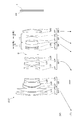
- FIG. 7 is a diagram showing a lens configuration of the variable magnification optical system ZL (3) according to the third embodiment.
- the variable magnification optical system ZL (3) has a first lens group G1 having a positive refractive power, a second lens group G2 having a negative refractive power, and a first lens group G2 having a positive refractive power arranged in order from the object side.
- the three lens group G3, the fourth lens group G4 having a positive refractive power, the aperture S, the fifth lens group G5 having a positive refractive power, the sixth lens group having a negative refractive power, and the positive It is composed of a seventh lens group G7 having a refractive power and an eighth lens group G8 having a negative refractive power.
- the image plane I is located after the eighth lens group G8.
- the 5th to 7th lens groups have a triplet structure with unevenness, which makes it easy to suppress aberration fluctuations during scaling. Further, since the eighth lens group having a negative refractive power is arranged behind the seventh lens group, the structure is close to the telephoto structure as a whole, and the back focus and the effect of shortening the total length of the optical system can be easily obtained.
- the fifth lens group G5 functions as the first focusing lens group F1
- the sixth lens group G6 functions as the second focusing lens group F2.
- the second focusing lens group also functions as a teleconverter that expands the focal length of the first to fifth lens groups.
- the second lens group G2, the third lens group G3, the fifth lens group G5, the sixth lens group G6, and the eighth lens group G8 are used when the magnification is changed from the wide-angle end state (W) to the telephoto end state (T). In addition, it moves along the locus indicated by the arrow in the lower part of FIG. As a result, the distance between adjacent lens groups changes, and the shooting magnification is changed (magnification is performed).
- the first lens group G1, the fourth lens group G5, and the seventh lens group G7 are fixed and do not move during scaling. When focusing from an infinity object to a short-range object, the fifth lens group G5 and the sixth lens group G6 move to the image plane side in different trajectories as shown by the arrows in the upper part of FIG.
- the first lens group G1 is composed of a negative meniscus lens L11 having a convex surface facing the object side, a bonded positive lens L12 having a biconvex positive lens L12, and a positive meniscus lens L13 having a convex surface facing the object side.
- the second lens group G2 includes a negative meniscus lens L21 having a convex surface facing the object side, a negative lens L22 having a biconcave shape and a positive lens L23 having a biconvex shape, and a negative lens L24 having a biconcave shape. Consists of.
- the third lens group G3 is composed of a positive meniscus lens L31 with a concave surface facing the object side.
- the fourth lens group G4 is composed of a biconvex positive lens L41, a biconvex positive lens L42, and a biconcave negative lens L43.
- the fifth lens group G5 is composed of a negative meniscus lens L51 with a convex surface facing the object side and a biconvex positive lens L52.
- the sixth lens group G6 is composed of a junction negative lens of a biconvex positive lens L61 and a biconcave negative lens L62.
- the seventh lens group G7 is composed of a negative meniscus lens L71 with a convex surface facing the object side and a biconvex positive lens L72.
- the eighth lens group G8 is composed of a biconcave negative lens L81. Further, a parallel flat plate PP is arranged in front of the image plane I.
- Table 3 lists the values of the specifications of the variable magnification optical system according to the third embodiment.
- FIG. 8 shows various aberration values of the variable magnification optical system according to the third embodiment in the infinity object in-focus state
- FIG. 9 shows various aberration values of the variable-magnification optical system according to the third embodiment in the close-range object in-focus state.
- A shows various aberration values in the wide-angle end state
- B shows various aberration values in the intermediate focal length
- C shows various aberration values in the telephoto end state. From each aberration diagram, the variable magnification optical system according to the third embodiment satisfactorily corrects various aberrations when focusing from an infinity object to a short-distance object in the entire range from the wide-angle end state to the telephoto end state. It can be seen that aberration fluctuations can be effectively suppressed.
- FIG. 10 is a diagram showing a lens configuration of the variable magnification optical system ZL (4) according to the fourth embodiment.
- the variable magnification optical system ZL (4) has a first lens group G1 having a positive refractive power, a second lens group G2 having a negative refractive power, and a first lens group G2 having a positive refractive power arranged in order from the object side.
- It is composed of a sixth lens group having a positive refractive power, a seventh lens group G7 having a positive refractive power, and an eighth lens group having a negative refractive power.
- the image plane I is located after the eighth lens group G8.
- the 5th to 7th lens groups have a triplet structure with unevenness, which makes it easy to suppress aberration fluctuations during scaling. Further, since the eighth lens group having a negative refractive power is arranged behind the seventh lens group, the structure is close to the telephoto structure as a whole, and the back focus and the effect of shortening the total length of the optical system can be easily obtained.
- the fifth lens group G5 functions as the first focusing lens group F1
- the sixth lens group G6 functions as the second focusing lens group F2.
- the second focusing lens group also functions as a teleconverter that expands the focal length of the first to fifth lens groups.
- the first lens group G1, the second lens group G2, the fourth lens group G4, the fifth lens group G5, the sixth lens group G6, and the eighth lens group G8 are in the wide-angle end state (W) to the telephoto end state (T).
- W wide-angle end state
- T telephoto end state
- the lens moves along the trajectory indicated by the arrow in the lower part of FIG.
- the second lens group G2 is fixed and does not move when the magnification is changed.
- the fifth lens group G5 and the sixth lens group G6 move to the image plane side in different trajectories as shown by the arrows in the upper part of FIG.
- the first lens group G1 is composed of a positive meniscus lens L11 having a convex surface facing the object side, a negative meniscus lens L12 having a convex surface facing the object side, and a positive meniscus lens L13 having a convex surface facing the object side. It is composed.
- the second lens group G2 includes a negative meniscus lens L21 having a convex surface facing the object side, a negative meniscus lens L22 having a convex surface facing the object side, and a positive meniscus lens L23 having a convex surface facing the object side. It is composed of a biconcave negative lens L24.
- the third lens group G3 is composed of a biconvex positive lens L31.
- the fourth lens group G4 is composed of a biconvex positive lens L41, a biconvex positive lens L42, and a biconcave negative lens L43.
- the fifth lens group G5 is composed of a positive meniscus lens L51 with a concave surface facing the object side, an aperture diaphragm S, and a biconvex positive lens L52.
- the sixth lens group G6 is composed of a junction negative lens of a positive meniscus lens L61 with a concave surface facing the object side and a negative lens L62 having a biconcave shape.
- the seventh lens group G7 is composed of a negative meniscus lens L71 with a convex surface facing the object side and a biconvex positive lens L72.
- the eighth lens group G8 is composed of a biconcave negative lens L81. Further, a parallel flat plate PP is arranged in front of the image plane I.
- Table 4 lists the values of the specifications of the variable magnification optical system according to the fourth embodiment.
- FIG. 11 shows various aberration values of the variable magnification optical system according to the fourth embodiment in the infinity object in-focus state
- FIG. 12 shows various aberration values of the variable-magnification optical system according to the fourth embodiment in the close-range object in-focus state.
- A shows various aberration values in the wide-angle end state
- B shows various aberration values in the intermediate focal length
- C shows various aberration values in the telephoto end state. From each aberration diagram, the variable magnification optical system according to the fourth embodiment satisfactorily corrects various aberrations when focusing from an infinity object to a short-distance object in the entire range from the wide-angle end state to the telephoto end state. It can be seen that aberration fluctuations can be effectively suppressed.
- Example 1 Example 2 Example 3
- Example 4 (1) 0.213 0.192 0.243 0.207 (2) 26.520 23.780 25.640 25.640 (3) 1.006 0.960 1.036 0.977 (4) 0.136 0.222 0.155 0.121 (5) 0.163 0.124 0.089 0.050 (6) 0.618 0.665 1.432 2.140 (7) 0.648 0.591 0.626 0.624 (8) 0.418 0.374 0.381 0.372 (9) 0.391 0.331 0.233 0.135 (10) 0.127 0.108 0.111 0.107 (11) 0.115 0.089 0.049 0.018 (12) 26.520 23.780 25.640 25.640 (13) 0.084 0.079 0.095 0.084 (14) 0.711 0.664 0.368 0.358
- the present invention is not limited to the above embodiment, and can be appropriately modified as long as the optical performance specified by the description of each claim is not impaired.
- variable magnification optical system having other group configurations (for example, a lens or a lens or an image plane side of the variable magnification optical system on the most object side or the most image plane side) It is also possible to have a configuration in which a lens group is added, etc.).
- the lens group refers to a portion having at least one lens separated by an air interval that changes at the time of magnification change or focusing.
- the aperture diaphragm is arranged in the third lens group, the fourth lens group, or the fifth lens group in each of the above embodiments, the aperture diaphragm is not provided as the aperture diaphragm, and the lens frame is used. A form in which the role is substituted is conceivable.
- the lens surface may be spherical, flat or aspherical.
- the spherical or flat lens surface facilitates lens processing and assembly adjustment, can prevent deterioration of optical performance due to errors in lens processing and assembly adjustment, and further deteriorates depiction performance even if the image surface shifts. It has the advantage of being less.
- the aspherical lens surface may be an aspherical surface obtained by grinding, a glass-molded aspherical surface obtained by molding glass into an aspherical shape, or a composite aspherical surface formed by forming a resin provided on the glass surface into an aspherical shape. Good.
- the lens surface may be a diffraction surface, and the lens may be a refractive index distribution type lens (GRIN lens) or a plastic lens.
- GRIN lens refractive index distribution type lens
- An antireflection film having a high transmittance in a wide wavelength range may be applied to each lens surface in order to reduce flare and ghost and achieve high contrast optical performance.
- G1 1st lens group G2 2nd lens group G3 3rd lens group G4 4th lens group G5 5th lens group G6 6th lens group G7 7th lens group G8 8th lens group I Image plane S Aperture aperture
Abstract
This variable magnification optical system comprises a front lens group and a rear lens group, which are arranged in order from the object side along an optical axis, and the rear lens group includes a first focusing lens group having positive refractive power, and a second focusing lens group disposed on the image surface side of the first focusing lens group and having negative refractive power. When the magnification is changed, the spacing between lens groups adjacent to each other changes, at the time of changing from focusing on an object at infinity to focusing on an object at a short distance, the position of the front lens group is fixed, the first focusing lens group and the second focusing lens group respectively move to the image surface side along different trajectories, and the following conditional expression is satisfied. 0.05 < (-fF2)/ft < 0.50 where fF2 is the focal length of the second focusing lens group, and ft is the focal length of the variable magnification optical system in a telephoto end state.
Description
本発明は、変倍光学系、光学機器および変倍光学系の製造方法に関する。
The present invention relates to a variable magnification optical system, an optical instrument, and a method for manufacturing the variable magnification optical system.
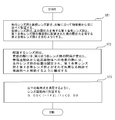
写真用カメラ、電子スチルカメラ、ビデオカメラ等に適したズームレンズとして、像面に近い位置に配置されたレンズ群(後群)の一部を移動させて合焦を行うズームレンズが提案されている(例えば、特許文献1を参照)。このようなズームレンズでは、像面湾曲等の諸収差を抑制し、合焦時に良好な光学性能を実現することが求められる。
As a zoom lens suitable for photographic cameras, electronic still cameras, video cameras, etc., a zoom lens has been proposed in which a part of a lens group (rear group) arranged near the image plane is moved to focus. (See, for example, Patent Document 1). In such a zoom lens, it is required to suppress various aberrations such as curvature of field and realize good optical performance at the time of focusing.
第1の本発明に係る変倍光学系は、光軸に沿って物体側から順に並んだ先行レンズ群と後続レンズ群からなり、後続レンズ群は、正の屈折力を有する第1合焦レンズ群と、第1合焦レンズ群の像面側に配置された負の屈折力を有する第2合焦レンズ群とを含む。変倍の際には、隣り合う各レンズ群の間隔が変化し、無限遠物体から近距離物体への合焦の際には、先行レンズ群の位置は固定され、第1合焦レンズ群と第2合焦レンズ群とがそれぞれ異なる軌跡で像面側へと移動し、以下の条件式を満足する。
0.05<(-fF2)/ft<0.50
但し、
fF2:第2合焦レンズ群の焦点距離
ft :望遠端状態における変倍光学系の焦点距離 The first variable magnification optical system according to the present invention includes a preceding lens group and a succeeding lens group arranged in order from the object side along the optical axis, and the succeeding lens group is a first focusing lens having a positive refractive power. The group and a second focusing lens group having a negative refractive power arranged on the image plane side of the first focusing lens group are included. At the time of scaling, the distance between adjacent lens groups changes, and at the time of focusing from an infinity object to a short-range object, the position of the preceding lens group is fixed, and it becomes the first focusing lens group. The second focusing lens group moves to the image plane side with different trajectories, and satisfies the following conditional expression.
0.05 <(-fF2) / ft <0.50
However,
fF2: Focal length of the second focusing lens group ft: Focal length of the variable magnification optical system in the telephoto end state
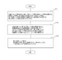
第2の本発明に係る変倍光学系は、光軸に沿って物体側から順に並んだ、先行レンズ群と後続レンズ群からなり、前記先行レンズ群は、光軸に沿って物体側から順に並んだ、正の屈折力を有する第1レンズ群と、負の屈折力を有する第2レンズ群とを含み、前記後続レンズ群は、正の屈折力を有する第1合焦レンズ群と、前記第1合焦レンズ群の像面側に配置された負の屈折力を有する第2合焦レンズ群とを含み、広角端状態から望遠端状態への変倍の際には、隣り合う各レンズ群の間隔が変化し、前記第1合焦レンズ群と前記第2合焦レンズ群とがそれぞれ異なる軌跡で物体側へと移動し、無限遠物体から近距離物体への合焦の際には、前記第1合焦レンズ群と前記第2合焦レンズ群とがそれぞれ異なる軌跡で像面側へと移動する。
The second variable magnification optical system according to the present invention comprises a preceding lens group and a succeeding lens group arranged in order from the object side along the optical axis, and the preceding lens group is sequentially arranged from the object side along the optical axis. The following lens group includes a first lens group having a positive refractive force and a second lens group having a negative refractive force, and the subsequent lens group includes a first focusing lens group having a positive refractive force and the above-mentioned Includes a second focusing lens group having a negative refractive force arranged on the image plane side of the first focusing lens group, and adjacent lenses when scaling from the wide-angle end state to the telephoto end state. When the distance between the groups changes, the first focusing lens group and the second focusing lens group move toward the object side with different trajectories, and when focusing from an infinity object to a short-range object, The first focusing lens group and the second focusing lens group move to the image plane side with different trajectories.
第3の本発明に係る変倍光学系は、光軸に沿って物体側から順に並んだ、先行レンズ群と後続レンズ群からなり、後続レンズ群は、正の屈折力を有する第1合焦レンズ群と、第1合焦レンズ群の像面側に配置された負の屈折力を有する第2合焦レンズ群とを含む。変倍の際には、隣り合う各レンズ群の間隔が変化し、無限遠物体から近距離物体への合焦の際には、先行レンズ群の位置は固定され、第1合焦レンズ群と第2合焦レンズ群とがそれぞれ異なる軌跡で像面側へと移動する。第2合焦レンズ群は、物体側から順に並んで配置された1枚の正レンズと1枚の負レンズとを有する。
The third variable magnification optical system according to the present invention consists of a preceding lens group and a succeeding lens group arranged in order from the object side along the optical axis, and the succeeding lens group is a first focusing having a positive refractive power. It includes a lens group and a second focusing lens group having a negative refractive power arranged on the image plane side of the first focusing lens group. At the time of scaling, the distance between adjacent lens groups changes, and at the time of focusing from an infinity object to a short-range object, the position of the preceding lens group is fixed, and it becomes the first focusing lens group. The second focusing lens group moves to the image plane side with different trajectories. The second focusing lens group includes one positive lens and one negative lens arranged in order from the object side.
本発明に係る光学機器は、上記変倍光学系を搭載して構成される。
The optical device according to the present invention is configured to include the above variable magnification optical system.
第1の本発明に係る変倍光学系の製造方法は、以下のとおり、各レンズ群を構成しレンズ鏡筒内に配置する。変倍光学系は、光軸に沿って物体側から順に並んだ先行レンズ群と後続レンズ群からなり、後続レンズ群は、正の屈折力を有する第1合焦レンズ群と、第1合焦レンズ群の像面側に配置された負の屈折力を有する第2合焦レンズ群とを含む。変倍の際には、隣り合う各レンズ群の間隔が変化し、無限遠物体から近距離物体への合焦の際には、先行レンズ群の位置は固定され、第1合焦レンズ群と第2合焦レンズ群とがそれぞれ異なる軌跡で像面側へと移動し、以下の条件式を満足する。
0.05<(-fF2)/ft<0.50
但し、
fF2:第2合焦レンズ群の焦点距離
ft :望遠端状態における変倍光学系の焦点距離 In the first method for manufacturing a variable magnification optical system according to the present invention, each lens group is configured and arranged in a lens barrel as follows. The variable magnification optical system consists of a leading lens group and a trailing lens group arranged in order from the object side along the optical axis, and the trailing lens group includes a first focusing lens group having a positive refractive power and a first focusing lens group. It includes a second focusing lens group having a negative refractive power arranged on the image plane side of the lens group. At the time of scaling, the distance between adjacent lens groups changes, and at the time of focusing from an infinity object to a short-range object, the position of the preceding lens group is fixed, and it becomes the first focusing lens group. The second focusing lens group moves to the image plane side with different trajectories, and satisfies the following conditional expression.
0.05 <(-fF2) / ft <0.50
However,
fF2: Focal length of the second focusing lens group ft: Focal length of the variable magnification optical system in the telephoto end state
第2の本発明に係る変倍光学系の製造方法は、以下のとおり、各レンズ群を構成しレンズ鏡筒内に配置する。光軸に沿って物体側から順に、先行レンズ群と後続レンズ群を配置する。先行レンズ群は、光軸に沿って物体側から順に並んだ、正の屈折力を有する第1レンズ群と、負の屈折力を有する第2レンズ群とを含むようにする。後続レンズ群は、正の屈折力を有する第1合焦レンズ群と、第1合焦レンズ群の像面側に配置された負の屈折力を有する第2合焦レンズ群とを含むようにする。広角端状態から望遠端状態への変倍の際には、隣り合う各レンズ群の間隔が変化し、第1合焦レンズ群と第2合焦レンズ群とがそれぞれ異なる軌跡で物体側へと移動し、無限遠物体から近距離物体への合焦の際には、第1合焦レンズ群と第2合焦レンズ群とがそれぞれ異なる軌跡で像面側へと移動するように、レンズ群を構成する。
The second method for manufacturing a variable magnification optical system according to the present invention is as follows, in which each lens group is configured and arranged in a lens barrel. The leading lens group and the succeeding lens group are arranged in order from the object side along the optical axis. The leading lens group includes a first lens group having a positive refractive power and a second lens group having a negative refractive power arranged in order from the object side along the optical axis. The subsequent lens group includes a first focusing lens group having a positive refractive power and a second focusing lens group having a negative refractive power arranged on the image plane side of the first focusing lens group. To do. When scaling from the wide-angle end state to the telephoto end state, the distance between adjacent lens groups changes, and the first focusing lens group and the second focusing lens group move toward the object with different trajectories. When moving and focusing from an infinity object to a short-range object, the lens group moves so that the first focusing lens group and the second focusing lens group move toward the image plane with different trajectories. To configure.
第3の本発明に係る変倍光学系の製造方法は、以下のとおり、各レンズ群を構成しレンズ鏡筒内に配置する。光軸に沿って物体側から順に、先行レンズ群と後続レンズ群を配置する。後続レンズ群は、正の屈折力を有する第1合焦レンズ群と、第1合焦レンズ群の像面側に配置された負の屈折力を有する第2合焦レンズ群とを含むようにする。変倍の際には、隣り合う各レンズ群の間隔が変化し、無限遠物体から近距離物体への合焦の際には、先行レンズ群の位置は固定され、第1合焦レンズ群と第2合焦レンズ群とがそれぞれ異なる軌跡で像面側へと移動するように、レンズ群を構成する。第2合焦レンズ群は、物体側から順に並んで配置された1枚の正レンズと1枚の負レンズとを有するようにする。
The third method for manufacturing a variable magnification optical system according to the present invention is as follows, in which each lens group is configured and arranged in a lens barrel. The leading lens group and the succeeding lens group are arranged in order from the object side along the optical axis. The subsequent lens group includes a first focusing lens group having a positive refractive power and a second focusing lens group having a negative refractive power arranged on the image plane side of the first focusing lens group. To do. At the time of scaling, the distance between adjacent lens groups changes, and at the time of focusing from an infinity object to a short-range object, the position of the preceding lens group is fixed, and it becomes the first focusing lens group. The lens group is configured so that the second focusing lens group moves toward the image plane side with different trajectories. The second focusing lens group has one positive lens and one negative lens arranged in order from the object side.
以下、本発明に係る好ましい実施形態について説明する。図13に、光学機器の一実施形態であるデジタルカメラの概略構成を示す。デジタルカメラ1は、本体2と本体2に着脱可能な撮影レンズ3により構成される。本体2は、撮像素子4と、デジタルカメラの動作を制御する本体制御部(不図示)と、液晶操作画面5を備える。撮影レンズ3は、複数のレンズ群からなる変倍光学系ZLと、各レンズ群の位置を制御するレンズ位置制御機構(不図示)を備える。レンズ位置制御機構は、レンズ群の位置を検出するセンサ、レンズ群を光軸に沿って前後に移動させるモーター、モーターを駆動する制御回路などにより構成される。
Hereinafter, preferred embodiments according to the present invention will be described. FIG. 13 shows a schematic configuration of a digital camera, which is an embodiment of an optical device. The digital camera 1 is composed of a main body 2 and a photographing lens 3 that can be attached to and detached from the main body 2. The main body 2 includes an image sensor 4, a main body control unit (not shown) that controls the operation of a digital camera, and a liquid crystal operation screen 5. The photographing lens 3 includes a variable magnification optical system ZL composed of a plurality of lens groups and a lens position control mechanism (not shown) for controlling the position of each lens group. The lens position control mechanism is composed of a sensor that detects the position of the lens group, a motor that moves the lens group back and forth along the optical axis, a control circuit that drives the motor, and the like.
被写体からの光は、撮影レンズ3の変倍光学系ZLにより集光されて、撮像素子4の像面I上に到達する。像面Iに到達した被写体からの光は、撮像素子4により光電変換され、デジタル画像データとして不図示のメモリに記録される。メモリに記録されたデジタル画像データは、ユーザの操作に応じて液晶画面5に表示される。以下、変倍光学系ZLについて、詳細に説明する。
The light from the subject is collected by the variable magnification optical system ZL of the photographing lens 3 and reaches the image plane I of the image sensor 4. The light from the subject that has reached the image plane I is photoelectrically converted by the image sensor 4 and recorded as digital image data in a memory (not shown). The digital image data recorded in the memory is displayed on the liquid crystal screen 5 according to the user's operation. Hereinafter, the variable magnification optical system ZL will be described in detail.
第1実施形態の変倍光学系は、光軸に沿って物体側から順に並んだ先行レンズ群と後続レンズ群からなり、後続レンズ群は、正の屈折力を有する第1合焦レンズ群と、第1合焦レンズ群の像面側に配置された負の屈折力を有する第2合焦レンズ群とを含む。変倍の際には、隣り合う各レンズ群の間隔が変化し、無限遠物体から近距離物体への合焦の際には、先行レンズ群の位置は固定され、第1合焦レンズ群と第2合焦レンズ群とがそれぞれ異なる軌跡で像面側へと移動し、以下の条件式(1)を満足する。
0.05<(-fF2)/ft<0.50 ・・・(1)
但し、
fF2:第2合焦レンズ群の焦点距離
ft :望遠端状態における変倍光学系の焦点距離 The variable magnification optical system of the first embodiment consists of a preceding lens group and a succeeding lens group arranged in order from the object side along the optical axis, and the succeeding lens group includes a first focusing lens group having a positive refractive power. , Includes a second focusing lens group having a negative refractive power arranged on the image plane side of the first focusing lens group. At the time of scaling, the distance between adjacent lens groups changes, and at the time of focusing from an infinity object to a short-range object, the position of the preceding lens group is fixed, and it becomes the first focusing lens group. The second focusing lens group moves to the image plane side with different trajectories, and satisfies the following conditional equation (1).
0.05 <(−fF2) / ft <0.50 ・ ・ ・ (1)
However,
fF2: Focal length of the second focusing lens group ft: Focal length of the variable magnification optical system in the telephoto end state
上記構成では、主として第2合焦レンズ群の移動により合焦が行われ、第2合焦レンズ群の移動により変動した収差が、第1合焦レンズ群により補正される。条件式(1)は、第2合焦レンズ群の焦点距離と望遠端状態における変倍光学系の焦点距離との比を規定するもので、第2合焦レンズ群のパワーの適切な範囲を示している。この条件式を満足することで、無限遠物体から至近距離物体への合焦の際、像面湾曲、球面収差、色収差などの諸収差を良好に補正し、収差変動を効果的に抑えることができる。
In the above configuration, focusing is mainly performed by the movement of the second focusing lens group, and the aberration fluctuating due to the movement of the second focusing lens group is corrected by the first focusing lens group. Conditional expression (1) defines the ratio between the focal length of the second focusing lens group and the focal length of the variable magnification optical system in the telephoto end state, and determines the appropriate range of power of the second focusing lens group. Shown. By satisfying this conditional expression, various aberrations such as curvature of field, spherical aberration, and chromatic aberration can be satisfactorily corrected when focusing from an infinity object to a close-range object, and aberration fluctuations can be effectively suppressed. it can.
条件式(1)の対応値が上限値0.50を上回ると、第2合焦レンズ群の屈折力が弱くなり、近距離合焦時に像面湾曲などの諸収差を補正し、収差変動を抑えることが難しくなる。本実施形態の効果を確実なものとするためには、条件式(1)の上限値は、より小さな値、例えば0.45、0.40、0.38、0.35、0.33、0.30、0.28、または0.25とすることが好ましい。
When the corresponding value of the conditional expression (1) exceeds the upper limit value of 0.50, the refractive power of the second focusing lens group becomes weak, and various aberrations such as curvature of field are corrected during short-distance focusing to reduce aberration fluctuations. It becomes difficult to suppress. In order to ensure the effect of the present embodiment, the upper limit of the conditional expression (1) is a smaller value, for example, 0.45, 0.40, 0.38, 0.35, 0.33, It is preferably 0.30, 0.28, or 0.25.
条件式(1)の対応値が下限値0.05を下回ると、第2合焦レンズ群の屈折力が強くなり、球面収差などの諸収差を良好に補正することが難しくなる。本実施形態の効果を確実なものとするためには、条件式(1)の下限値を、より大きな値、例えば0.08、0.10、0.13、0.15、または0,18とすることが好ましい。
When the corresponding value of the conditional expression (1) is less than the lower limit value of 0.05, the refractive power of the second focusing lens group becomes strong, and it becomes difficult to satisfactorily correct various aberrations such as spherical aberration. In order to ensure the effect of the present embodiment, the lower limit of the conditional expression (1) is set to a larger value, for example, 0.08, 0.10, 0.13, 0.15, or 0,18. Is preferable.
第1実施形態の変倍光学系は、上記構成で上記条件式を満たすことにより、広角端状態から望遠端状態までの全域に亘り、諸収差を良好に補正することができ、近距離合焦時にも高い光学性能を実現することができる。
The variable magnification optical system of the first embodiment can satisfactorily correct various aberrations over the entire range from the wide-angle end state to the telephoto end state by satisfying the above conditional expression with the above configuration, and can focus at a short distance. High optical performance can be achieved at times.
第2実施形態の変倍光学系は、光軸に沿って物体側から順に並んだ、先行レンズ群と後続レンズ群からなり、先行レンズ群は、光軸に沿って物体側から順に並んだ、正の屈折力を有する第1レンズ群と、負の屈折力を有する第2レンズ群とを含み、後続レンズ群は、正の屈折力を有する第1合焦レンズ群と、第1合焦レンズ群の像面側に配置された負の屈折力を有する第2合焦レンズ群とを含む。広角端状態から望遠端状態への変倍の際には、隣り合う各レンズ群の間隔が変化し、第1合焦レンズ群と第2合焦レンズ群とがそれぞれ異なる軌跡で物体側へと移動し、無限遠物体から近距離物体への合焦の際には、第1合焦レンズ群と第2合焦レンズ群とがそれぞれ異なる軌跡で像面側へと移動する。
The variable magnification optical system of the second embodiment consists of a leading lens group and a succeeding lens group arranged in order from the object side along the optical axis, and the leading lens group is arranged in order from the object side along the optical axis. A first lens group having a positive refractive power and a second lens group having a negative refractive power are included, and subsequent lens groups include a first focusing lens group having a positive refractive power and a first focusing lens. It includes a second focusing lens group having a negative refractive force arranged on the image plane side of the group. When scaling from the wide-angle end state to the telephoto end state, the distance between adjacent lens groups changes, and the first in-focus lens group and the second in-focus lens group move toward the object with different trajectories. When moving from an infinity object to a short-range object, the first focusing lens group and the second focusing lens group move to the image plane side with different trajectories.
第2実施形態の変倍光学系は、上記構成により、広角端状態から望遠端状態までの全域に亘り、諸収差を良好に補正することができ、近距離合焦時にも高い光学性能を実現することができる。
With the above configuration, the variable magnification optical system of the second embodiment can satisfactorily correct various aberrations over the entire range from the wide-angle end state to the telephoto end state, and realizes high optical performance even during short-distance focusing. can do.
第3実施形態の変倍光学系は、光軸に沿って物体側から順に並んだ、先行レンズ群と後続レンズ群からなり、後続レンズ群は、正の屈折力を有する第1合焦レンズ群と、第1合焦レンズ群の像面側に配置された負の屈折力を有する第2合焦レンズ群とを含む。変倍の際には、隣り合う各レンズ群の間隔が変化し、無限遠物体から近距離物体への合焦の際には、先行レンズ群の位置は固定され、第1合焦レンズ群と第2合焦レンズ群とがそれぞれ異なる軌跡で像面側へと移動する。第2合焦レンズ群は、物体側から順に並んで配置された1枚の正レンズと1枚の負レンズとを有する。
The variable magnification optical system of the third embodiment consists of a preceding lens group and a succeeding lens group arranged in order from the object side along the optical axis, and the succeeding lens group is a first focusing lens group having a positive refractive power. And a second focusing lens group having a negative refractive power arranged on the image plane side of the first focusing lens group. At the time of scaling, the distance between adjacent lens groups changes, and at the time of focusing from an infinity object to a short-range object, the position of the preceding lens group is fixed, and it becomes the first focusing lens group. The second focusing lens group moves to the image plane side with different trajectories. The second focusing lens group includes one positive lens and one negative lens arranged in order from the object side.
第3実施形態の変倍光学系では、主として第2合焦レンズ群の移動により合焦が行われ、第2合焦レンズ群の移動により変動した収差が、第1合焦レンズ群により補正される。このような構成の変倍光学系では、第2合焦レンズ群を1枚のレンズで構成すると諸収差を良好に補正することが難しくなり、レンズの枚数が多くなると合焦レンズ群が重くなり高速フォーカシングを実現することが難しくなる。これに対し、第2合焦レンズ群を、1枚の正レンズと1枚の負レンズとを有する構成とした場合、レンズ群を大きく動かしても色収差をはじめとする諸収差の変動を抑えることができ、合焦レンズ群の小型軽量化による高速フォーカシングも実現することができ、像面移動係数を下げられるという利点もある。上記構成は、特に望遠系あるいは高倍率のレンズに適している。
In the variable magnification optical system of the third embodiment, focusing is mainly performed by the movement of the second focusing lens group, and the aberration fluctuating due to the movement of the second focusing lens group is corrected by the first focusing lens group. The lens. In a variable magnification optical system having such a configuration, if the second focusing lens group is composed of one lens, it becomes difficult to satisfactorily correct various aberrations, and as the number of lenses increases, the focusing lens group becomes heavy. It becomes difficult to realize high-speed focusing. On the other hand, when the second focusing lens group has one positive lens and one negative lens, fluctuations in various aberrations such as chromatic aberration can be suppressed even if the lens group is moved significantly. It is possible to realize high-speed focusing by reducing the size and weight of the focusing lens group, and there is an advantage that the image plane movement coefficient can be lowered. The above configuration is particularly suitable for telephoto lenses or high magnification lenses.
また、上記構成では、第2合焦レンズ群を構成するレンズを正レンズ、負レンズの順に配置することで、負、正の順に配置する構成よりも諸収差を良好に補正することができる。負、正の順に配置した構成では、負レンズを通る軸外の光線が光軸から離れ、正レンズを通る光線高も上がるため、収差を補正することが難しくなる。また軸上の光束も発散するため、同じく正レンズを通る光線高が上がり、球面収差の補正が難しくなる。
Further, in the above configuration, by arranging the lenses constituting the second focusing lens group in the order of the positive lens and the negative lens, various aberrations can be corrected better than the configuration in which the lenses are arranged in the order of negative and positive. In the configuration in which the rays are arranged in the order of negative and positive, the off-axis light rays passing through the negative lens are separated from the optical axis and the height of the light rays passing through the positive lens is also increased, which makes it difficult to correct the aberration. In addition, since the luminous flux on the axis is also diverged, the height of the light beam passing through the positive lens also rises, which makes it difficult to correct spherical aberration.
第1実施形態および第2実施形態の変倍光学系において、第2合焦レンズ群は、物体側から順に並んで配置された1枚の正レンズと1枚の負レンズとを有することが好ましい。これにより、至近距離に合焦した際に、諸収差を良好に補正することができ、高い光学性能を実現することができる。
In the variable magnification optical system of the first embodiment and the second embodiment, the second focusing lens group preferably has one positive lens and one negative lens arranged side by side from the object side. .. As a result, various aberrations can be satisfactorily corrected when focusing at a close distance, and high optical performance can be realized.
第3実施形態の変倍光学系は、さらに以下の条件式(2)を満足することが好ましい。第1実施形態および第2実施形態の変倍光学系は、第2合焦レンズ群が正レンズと負レンズとを有する場合、さらに以下の条件式(2)を満足することが好ましい。
νd<37.00 ・・・(2)
但し、
νd:第2合焦レンズ群を構成する正レンズのアッベ数 The variable magnification optical system of the third embodiment further preferably satisfies the following conditional expression (2). When the second focusing lens group has a positive lens and a negative lens, the variable magnification optical system of the first embodiment and the second embodiment further preferably satisfies the following conditional expression (2).
νd <37.00 ・ ・ ・ (2)
However,
νd: Abbe number of positive lenses constituting the second focusing lens group
条件式(2)は、第2合焦レンズ群を構成する正レンズのアッベ数の適切な範囲を規定するものである。この条件式を満足することで、色収差を良好に補正することができる。条件式(2)の対応値が上限値37.00を上回ると、軸上色収差や倍率色収差を良好に補正することが難しくなる。本実施形態の効果を確実なものとするためには、条件式(2)の上限値を、より小さな値、例えば33.00または29.00とすることが好ましい。
Conditional expression (2) defines an appropriate range of Abbe numbers of the positive lenses constituting the second focusing lens group. By satisfying this conditional expression, chromatic aberration can be satisfactorily corrected. If the corresponding value of the conditional expression (2) exceeds the upper limit value of 37.00, it becomes difficult to satisfactorily correct axial chromatic aberration and chromatic aberration of magnification. In order to ensure the effect of the present embodiment, it is preferable that the upper limit value of the conditional expression (2) is a smaller value, for example, 33.00 or 29.00.
第3実施形態の変倍光学系は、さらに以下の条件式(3)を満足することが好ましい。第1実施形態および第2実施形態の変倍光学系は、第2合焦レンズ群が正レンズと負レンズとを有する場合、さらに以下の条件式(3)を満足することが好ましい。
0.80<NdF2n/NdF2p<1.25 ・・・(3)
但し、
NdF2n:第2合焦レンズ群を構成する負レンズのd線に対する屈折率
NdF2p:第2合焦レンズ群を構成する正レンズのd線に対する屈折率 The variable magnification optical system of the third embodiment further preferably satisfies the following conditional expression (3). When the second focusing lens group has a positive lens and a negative lens, the variable magnification optical system of the first embodiment and the second embodiment further preferably satisfies the following conditional expression (3).
0.80 <NdF2n / NdF2p <1.25 ... (3)
However,
NdF2n: Refractive index of the negative lens constituting the second focusing lens group with respect to the d line NdF2p: Refractive index of the positive lens constituting the second focusing lens group with respect to the d line
条件式(3)は、第2合焦レンズ群を構成する負レンズと正レンズの、屈折率の比を規定したものであり、2つのレンズの好ましい組み合わせを示している。この条件式を満足することで、諸収差を良好に補正し、収差変動を効果的に抑えることができる。
Conditional expression (3) defines the ratio of the refractive indexes of the negative lens and the positive lens constituting the second focusing lens group, and indicates a preferable combination of the two lenses. By satisfying this conditional expression, various aberrations can be satisfactorily corrected and aberration fluctuations can be effectively suppressed.
条件式(3)の対応値が上限値1.25を上回ると、負レンズの屈折力が相対的に弱くなり、近距離合焦時の像面湾曲などの諸収差を良好に補正することが難しくなる。本実施形態の効果を確実なものとするためには、条件式(3)の上限値を、より小さな値、例えば1.23、1.20、1.18、1.15、または1.11とすることが好ましい。
When the corresponding value of the conditional expression (3) exceeds the upper limit value of 1.25, the refractive power of the negative lens becomes relatively weak, and various aberrations such as curvature of field during short-distance focusing can be satisfactorily corrected. It gets harder. In order to ensure the effect of the present embodiment, the upper limit of the conditional expression (3) is set to a smaller value, for example, 1.23, 1.20, 1.18, 1.15, or 1.11. Is preferable.
条件式(3)の対応値が下限値0.80を下回ると、負レンズの屈折力が相対的に強くなり、ペッツバール和の補正が困難となる。本実施形態の効果を確実なものとするためには、条件式(3)の下限値を、より大きな値、例えば0.83、0.85、0.88、0.90、0.92、または0.95とすることが好ましい。
When the corresponding value of the conditional expression (3) is less than the lower limit value of 0.80, the refractive power of the negative lens becomes relatively strong, and it becomes difficult to correct the Petzval sum. In order to ensure the effect of the present embodiment, the lower limit of the conditional expression (3) is set to a larger value, for example, 0.83, 0.85, 0.88, 0.90, 0.92, Alternatively, it is preferably 0.95.
第1~第3実施形態の変倍光学系は、さらに以下の条件式(4)を満足することが好ましい。
0.05<MF1t/MF2t<0.40 ・・・(4)
但し、
MF1t:望遠端状態における前記第1合焦レンズ群の無限遠物体から至近距離物体への合焦の際の移動量
MF2t:望遠端状態における前記第2合焦レンズ群の無限遠物体から至近距離物体への合焦の際の移動量
(移動量は、像面側への移動を正の値で表す。) It is preferable that the variable magnification optical system of the first to third embodiments further satisfies the following conditional expression (4).
0.05 <MF1t / MF2t <0.40 ... (4)
However,
MF1t: Amount of movement when focusing from an infinity object of the first focusing lens group to a close-range object in the telephoto end state MF2t: Close distance from the infinity object of the second focusing lens group in the telephoto end state Amount of movement when focusing on an object (The amount of movement represents the movement toward the image plane as a positive value.)
条件式(4)は、無限遠物体から至近距離物体への合焦の際の2つの合焦レンズ群の移動量の比を規定するものである。合焦レンズ群を大きく変移させると収差の変動が大きくなるが、この条件式を満足することで、諸収差を良好に補正し、合焦時の収差変動を効果的に抑えることができる。
Conditional expression (4) defines the ratio of the amount of movement of the two focusing lens groups when focusing from an infinity object to a close-range object. When the focusing lens group is largely changed, the fluctuation of the aberration becomes large. However, by satisfying this conditional expression, various aberrations can be satisfactorily corrected and the fluctuation of the aberration at the time of focusing can be effectively suppressed.
条件式(4)の対応値が上限値0.40を上回ると、第2合焦レンズ群の動きが相対的に小さくなり、近距離合焦時に像面湾曲などの諸収差を良好に補正することが難しくなる。本実施形態の効果を確実なものとするためには、条件式(4)の上限値を、より小さな値、例えば0.38、0.35、0.34、0.30、0.28、または0.25とすることが好ましい。
When the corresponding value of the conditional expression (4) exceeds the upper limit value of 0.40, the movement of the second focusing lens group becomes relatively small, and various aberrations such as curvature of field are satisfactorily corrected during short-distance focusing. It becomes difficult. In order to ensure the effect of the present embodiment, the upper limit of the conditional expression (4) is set to a smaller value, for example, 0.38, 0.35, 0.34, 0.30, 0.28, Alternatively, it is preferably 0.25.
条件式(4)の対応値が下限値0.05を下回ると、第2合焦レンズ群の動きが相対的に大きくなり、負の像面湾曲が大きくなり、軸外収差の補正が難しくなる。本実施形態の効果を確実なものとするためには、条件式(4)の下限値を、より大きな値、例えば0.06、0.08、0.10、または0.11とすることが好ましい。
When the corresponding value of the conditional expression (4) is less than the lower limit value of 0.05, the movement of the second focusing lens group becomes relatively large, the negative curvature of field becomes large, and it becomes difficult to correct the off-axis aberration. .. In order to ensure the effect of this embodiment, the lower limit of the conditional expression (4) may be set to a larger value, for example, 0.06, 0.08, 0.10, or 0.11. preferable.
第1~第3実施形態の変倍光学系は、さらに以下の条件式(5)を満足することが好ましい。
0.04<βF1t/βF2t<0.20 ・・・(5)
但し、
βF1t:望遠端状態における第1合焦レンズ群の無限遠物体合焦時の横倍率
βF2t:望遠端状態における第2合焦レンズ群の無限遠物体合焦時の横倍率 It is preferable that the variable magnification optical system of the first to third embodiments further satisfies the following conditional expression (5).
0.04 <βF1t / βF2t <0.20 ... (5)
However,
βF1t: Lateral magnification when the first in-focus lens group is in focus at the telephoto end state βF2t: Lateral magnification when the second in-focus lens group is in focus at the telephoto end state
条件式(5)は、望遠端で無限遠物体に合焦した際の、第1合焦レンズ群と第2合焦レンズ群の横倍率の比を規定したものである。この条件式を満足することで、合焦の際の合焦レンズ群の移動量を抑えながら、諸収差を良好に補正することができる。
Conditional expression (5) defines the ratio of the lateral magnification of the first focusing lens group and the second focusing lens group when focusing on an infinity object at the telephoto end. By satisfying this conditional expression, various aberrations can be satisfactorily corrected while suppressing the amount of movement of the focusing lens group at the time of focusing.
条件式(5)の対応値が上限値0.20を上回ると、第1合焦レンズ群の横倍率が相対的に大きくなり、合焦レンズ群の移動量を抑えることや、球面収差を良好に補正することが難しくなる。本実施形態の効果を確実なものとするためには、条件式(5)の上限値を、より小さな値、例えば0.18、0.16、0.15、または0.14とすることが好ましい。
When the corresponding value of the conditional expression (5) exceeds the upper limit value of 0.20, the lateral magnification of the first focusing lens group becomes relatively large, the amount of movement of the focusing lens group is suppressed, and the spherical aberration is improved. It becomes difficult to correct to. In order to ensure the effect of the present embodiment, the upper limit of the conditional expression (5) may be set to a smaller value, for example, 0.18, 0.16, 0.15, or 0.14. preferable.
条件式(5)の対応値が下限値0.04を下回ると、第1合焦レンズ群の横倍率が相対的に小さくなり、像面湾曲や非点隔差を補正することが難しくなる。本実施形態の効果を確実なものとするためには、条件式(5)の下限値を、より大きな値、例えば0.05または0.06とすることが好ましい。
When the corresponding value of the conditional expression (5) is less than the lower limit value of 0.04, the lateral magnification of the first focusing lens group becomes relatively small, and it becomes difficult to correct curvature of field and non-point distance difference. In order to ensure the effect of the present embodiment, it is preferable to set the lower limit value of the conditional expression (5) to a larger value, for example, 0.05 or 0.06.
第1~第3実施形態の変倍光学系は、第2合焦レンズ群の像面側に第2合焦レンズ群と隣り合うように配置される後方レンズ群を有し、以下の条件式(6)を満足することが好ましい。
0.05<βF1w/βLGw<2.50 ・・・(6)
但し、
βF1w:広角端状態における第1合焦レンズ群の無限遠物体合焦時の横倍率
βLGw:広角端状態における後方レンズ群の無限遠物体合焦時の横倍率 The variable magnification optical system of the first to third embodiments has a rear lens group arranged adjacent to the second focusing lens group on the image plane side of the second focusing lens group, and has the following conditional expression. It is preferable to satisfy (6).
0.05 <βF1w / βLGw <2.50 ... (6)
However,
βF1w: Lateral magnification of the first focusing lens group when focusing on an infinity object in the wide-angle end state βLGw: Lateral magnification of the rear lens group when focusing on an infinity object in the wide-angle end state
条件式(6)は、広角端状態における第1合焦レンズ群の無限遠物体合焦時の横倍率と、広角端状態における後方レンズ群の無限遠物体合焦時の横倍率の比を規定するものである。この条件式を満足することで、光学系を大きくすることなく諸収差を良好に補正することができる。
Conditional expression (6) defines the ratio between the lateral magnification of the first focusing lens group when focusing on an infinity object in the wide-angle end state and the lateral magnification of the rear lens group when focusing on an infinity object in the wide-angle end state. To do. By satisfying this conditional expression, various aberrations can be satisfactorily corrected without enlarging the optical system.
条件式(6)の対応値が上限値2.50を上回ると、第1合焦レンズ群の横倍率が相対的に大きくなり、合焦時の移動量が大きくなる。これによる影響を軽減するために第2合焦レンズ群のパワーを強くすると、球面収差などの諸収差を良好に補正することが難しくなる。本実施形態の効果を確実なものとするためには、条件式(6)の上限値を、より小さな値、例えば2.45、2.40、2.38、2.35、2.30、2.25、2.20、2.00、1.80、1.60、または1.50とすることが好ましい。
When the corresponding value of the conditional expression (6) exceeds the upper limit value of 2.50, the lateral magnification of the first focusing lens group becomes relatively large, and the amount of movement during focusing becomes large. If the power of the second focusing lens group is increased in order to reduce the influence of this, it becomes difficult to satisfactorily correct various aberrations such as spherical aberration. In order to ensure the effect of this embodiment, the upper limit of the conditional expression (6) is set to a smaller value, for example, 2.45, 2.40, 2.38, 2.35, 2.30, It is preferably 2.25, 2.20, 2.00, 1.80, 1.60, or 1.50.
条件式(6)の対応値が下限値0.05を下回ると、第1合焦レンズ群の横倍率が小さい場合には像面湾曲や非点隔差を良好に補正することが難しくなり、第2合焦レンズ群の像面側の後方レンズ群の倍率が大きい場合には光学系の全長が長くなり小型化することが難しくなる。
When the corresponding value of the conditional expression (6) is less than the lower limit value of 0.05, it becomes difficult to satisfactorily correct curvature of field and non-point separation when the lateral magnification of the first focusing lens group is small. When the magnification of the rear lens group on the image plane side of the two-focus lens group is large, the total length of the optical system becomes long and it becomes difficult to reduce the size.
第1~第3実施形態の変倍光学系は、さらに以下の条件式(7)を満足することが好ましい。
0.40<(-fF2)/fF1<0.80 ・・・(7)
但し、
fF1:第1合焦レンズ群の焦点距離
fF2:第2合焦レンズ群の焦点距離 It is preferable that the variable magnification optical system of the first to third embodiments further satisfies the following conditional expression (7).
0.40 <(-fF2) /fF1 <0.80 ... (7)
However,
fF1: Focal length of the first focusing lens group fF2: Focal length of the second focusing lens group
条件式(7)は、第1合焦レンズ群と第2合焦レンズ群の焦点距離の比を規定したものであり、2つの合焦レンズ群のパワーバランスの適切な範囲を示している。この条件式を満足することで、合焦の際の合焦レンズ群の移動量を抑えながら、諸収差を良好に補正することができる。
Conditional formula (7) defines the ratio of the focal lengths of the first focusing lens group and the second focusing lens group, and indicates an appropriate range of the power balance of the two focusing lens groups. By satisfying this conditional expression, various aberrations can be satisfactorily corrected while suppressing the amount of movement of the focusing lens group at the time of focusing.
条件式(7)の対応値が上限値0.80を上回ると、第2合焦レンズ群の屈折力が相対的に弱くなり、近距離合焦時に像面湾曲などの諸収差を補正することが難しくなる。本実施形態の効果を確実なものとするためには、条件式(7)の上限値を、より小さな値、例えば0.78、0.75、0.73、0.70、または0.68とすることが好ましい。
When the corresponding value of the conditional expression (7) exceeds the upper limit value of 0.80, the refractive power of the second focusing lens group becomes relatively weak, and various aberrations such as curvature of field are corrected during short-range focusing. Becomes difficult. In order to ensure the effect of the present embodiment, the upper limit of the conditional expression (7) is set to a smaller value, for example, 0.78, 0.75, 0.73, 0.70, or 0.68. Is preferable.
条件式(7)の対応値が下限値0.40を下回ると、第2合焦レンズ群の屈折力が相対的に強くなるため、近距離合焦時に負の像面湾曲が大きくなり、軸外収差を補正することが難しくなる。本実施形態の効果を確実なものとするためには、条件式(7)の下限値を、より大きな値、例えば0.43、0.45、0.48、0.50、0.53、0.55、または0.58とすることが好ましい。
When the corresponding value of the conditional expression (7) is less than the lower limit value of 0.40, the refractive power of the second focusing lens group becomes relatively strong, so that the negative curvature of field becomes large during short-range focusing, and the axis. It becomes difficult to correct external aberration. In order to ensure the effect of the present embodiment, the lower limit of the conditional expression (7) is set to a larger value, for example, 0.43, 0.45, 0.48, 0.50, 0.53, It is preferably 0.55 or 0.58.
また、第1~第3実施形態の変倍光学系は、後続レンズ群の最も像面に近い位置に、負の屈折力を有するレンズ成分が配置された構成とすることが好ましい。ここで、「レンズ成分」とは、そのレンズが、単レンズ、接合レンズのいずれでもよいことを意味する。光学系の最も後方に負のレンズ成分を配置することで、光学系の全長および最も後方のレンズ成分の径を小さくすることができ、光学系の小型化を実現しやすくなる。この構成はミラーレスタイプのカメラに適している。
Further, it is preferable that the variable magnification optical system of the first to third embodiments has a configuration in which a lens component having a negative refractive power is arranged at a position closest to the image plane of the subsequent lens group. Here, the "lens component" means that the lens may be either a single lens or a junction lens. By arranging the negative lens component at the rearmost position of the optical system, the overall length of the optical system and the diameter of the lens component at the rearmost position can be reduced, and it becomes easy to realize miniaturization of the optical system. This configuration is suitable for mirrorless type cameras.
また、第1~第3実施形態の変倍光学系は、光軸上に配置された絞りを有し、第1合焦レンズ群および前記第2合焦レンズ群が、絞りよりも像面に近い位置に配置されることが好ましい。これにより、合焦の際の倍率の変動を少なくすることができ、球面収差と像面湾曲をバランス良く補正することができる。
Further, the variable magnification optical system of the first to third embodiments has a diaphragm arranged on the optical axis, and the first focusing lens group and the second focusing lens group are closer to the image plane than the diaphragm. It is preferable that they are arranged in close positions. As a result, the fluctuation of the magnification at the time of focusing can be reduced, and the spherical aberration and the curvature of field can be corrected in a well-balanced manner.
また、第1~第3実施形態の変倍光学系において、第1合焦レンズ群と第2合焦レンズ群とは隣り合うように配置することが好ましい。これにより、合焦の際の球面収差と像面湾曲の変動を良好に抑えることができる。
Further, in the variable magnification optical system of the first to third embodiments, it is preferable to arrange the first focusing lens group and the second focusing lens group so as to be adjacent to each other. As a result, fluctuations in spherical aberration and curvature of field during focusing can be satisfactorily suppressed.
また、第1~第3実施形態の変倍光学系は、さらに以下の条件式(8)を満足することが好ましい。
0.00<βF1<0.90 ・・・(8)
但し、
βF1:広角端状態における第1合焦レンズ群の無限遠物体合焦時の横倍率 Further, it is preferable that the variable magnification optical system of the first to third embodiments further satisfies the following conditional expression (8).
0.00 <βF1 <0.90 ... (8)
However,
βF1: Lateral magnification when focusing on an infinity object of the first focusing lens group in the wide-angle end state
条件式(8)は、第1合焦レンズ群の無限遠物体合焦時の横倍率を規定するものである。この条件式(8)を満足することで、無限遠物体から近距離物体への合焦の際、球面収差をはじめとする諸収差の変動を抑え、全域に亘り高い光学性能を達成することができる。
Conditional expression (8) defines the lateral magnification of the first focusing lens group when focusing on an infinite object. By satisfying this conditional equation (8), it is possible to suppress fluctuations in various aberrations such as spherical aberration when focusing from an infinity object to a short-distance object, and to achieve high optical performance over the entire range. it can.
条件式(8)の対応値が上限値0.90を上回ると、合焦の際に諸収差の変動を抑えにくくなる。本実施形態の効果を確実なものとするためには、条件式(8)の上限値を、より小さな値、例えば0.85、0.80、0.75、0.70、0.65、0.60、0.55、0.50、0.45、または0.43とすることが好ましい。
If the corresponding value of the conditional expression (8) exceeds the upper limit value of 0.90, it becomes difficult to suppress fluctuations in various aberrations during focusing. In order to ensure the effect of the present embodiment, the upper limit of the conditional expression (8) is set to a smaller value, for example, 0.85, 0.80, 0.75, 0.70, 0.65, It is preferably 0.60, 0.55, 0.50, 0.45, or 0.43.
一方、条件式(8)の対応値が下限値0.00を下回ると、合焦の際に諸収差の変動を抑えにくくなる。本実施形態の効果を確実なものとするためには、条件式(7)の下限値を、より大きな値、例えば0.05、0.10、0.15、0.20、0.23、0.25、0.28、0.30、0.33、または0.35とすることが好ましい。
On the other hand, if the corresponding value of the conditional expression (8) is less than the lower limit value of 0.00, it becomes difficult to suppress fluctuations in various aberrations during focusing. In order to ensure the effect of the present embodiment, the lower limit of the conditional expression (7) is set to a larger value, for example, 0.05, 0.10, 0.15, 0.20, 0.23. It is preferably 0.25, 0.28, 0.30, 0.33, or 0.35.
また、第1~第3実施形態の変倍光学系は、さらに以下の条件式(9)を満足することが好ましい。
0.00<1/βF2<0.90 ・・・(9)
但し、
βF2:広角端状態における第2合焦レンズ群の無限遠物体合焦時の横倍率 Further, it is preferable that the variable magnification optical system of the first to third embodiments further satisfies the following conditional expression (9).
0.00 <1 / βF2 <0.90 ... (9)
However,
βF2: Lateral magnification when focusing on an infinity object of the second focusing lens group in the wide-angle end state
条件式(9)は、第2合焦レンズ群の無限遠物体合焦時の横倍率を規定するものである。この条件式(9)を満足することで、無限遠物体から近距離物体への合焦の際、球面収差をはじめとする諸収差の変動を抑え、全域に亘り高い光学性能を達成することができる。
Conditional expression (9) defines the lateral magnification of the second focusing lens group when focusing on an infinite object. By satisfying this conditional equation (9), it is possible to suppress fluctuations in various aberrations such as spherical aberration when focusing from an infinity object to a short-distance object, and to achieve high optical performance over the entire range. it can.
条件式(9)の対応値が上限値0.90を上回ると、合焦の際に諸収差の変動を抑えにくくなる。本実施形態の効果を確実なものとするためには、条件式(9)の上限値を、より小さな値、例えば0.85、0.80、0.75、0.70、0.65、0.60、0.55、0.53、0.50、0.48、0.45、0.43、または0.40とすることが好ましい。
If the corresponding value of the conditional expression (9) exceeds the upper limit value of 0.90, it becomes difficult to suppress fluctuations in various aberrations during focusing. In order to ensure the effect of the present embodiment, the upper limit of the conditional expression (9) is set to a smaller value, for example, 0.85, 0.80, 0.75, 0.70, 0.65, It is preferably 0.60, 0.55, 0.53, 0.50, 0.48, 0.45, 0.43, or 0.40.
一方、条件式(9)の対応値が下限値0.00を下回ると、合焦の際に諸収差の変動を抑えにくくなる。本実施形態の効果を確実なものとするためには、条件式(9)の下限値を、より大きな値、例えば0.03、0.05、0.08、0.10、または0.12とすることが好ましい。
On the other hand, if the corresponding value of the conditional expression (9) is less than the lower limit value of 0.00, it becomes difficult to suppress fluctuations in various aberrations during focusing. In order to ensure the effect of the present embodiment, the lower limit of the conditional expression (9) is set to a larger value, for example, 0.03, 0.05, 0.08, 0.10, or 0.12. Is preferable.
また、第1~第3実施形態の変倍光学系は、さらに以下の条件式(10)を満足することが好ましい。
{βF1+(1/βF1)}-2<0.25 ・・・(10)
但し、
βF1:広角端状態における第1合焦レンズ群の無限遠物体合焦時の横倍率 Further, it is preferable that the variable magnification optical system of the first to third embodiments further satisfies the following conditional expression (10).
{βF1 + (1 / βF1)} -2 <0.25 ... (10)
However,
βF1: Lateral magnification when focusing on an infinity object of the first focusing lens group in the wide-angle end state
条件式(10)は、第1合焦レンズ群の無限遠物体合焦時の横倍率が満たす条件を規定するものである。この条件式(10)を満足することで、無限遠物体から近距離物体への合焦の際、球面収差をはじめとする諸収差の変動を抑え、全域に亘り高い光学性能を達成することができる。
Conditional expression (10) defines the conditions that the lateral magnification of the first focusing lens group when focusing on an infinite object is satisfied. By satisfying this conditional equation (10), it is possible to suppress fluctuations in various aberrations such as spherical aberration when focusing from an infinity object to a short-distance object, and to achieve high optical performance over the entire range. it can.
条件式(10)の対応値が上限値0.25を上回ると、合焦の際に諸収差の変動を抑えにくくなる。本実施形態の効果を確実なものとするためには、条件式(10)の上限値を、より小さな値、例えば0.23、0.20、0.18、0.16、0.15、または0.13とすることが好ましい。
If the corresponding value of the conditional expression (10) exceeds the upper limit value of 0.25, it becomes difficult to suppress fluctuations in various aberrations during focusing. In order to ensure the effect of the present embodiment, the upper limit of the conditional expression (10) is set to a smaller value, for example, 0.23, 0.20, 0.18, 0.16, 0.15, Alternatively, it is preferably 0.13.
また、第1~第3実施形態の変倍光学系は、さらに以下の条件式(11)を満足することが好ましい。
{βF2+(1/βF2)}-2<0.25 ・・・(11)
但し、
βF2:広角端状態における第2合焦レンズ群の無限遠物体合焦時の横倍率 Further, it is preferable that the variable magnification optical system of the first to third embodiments further satisfies the following conditional expression (11).
{βF2 + (1 / βF2)} -2 <0.25 ... (11)
However,
βF2: Lateral magnification when focusing on an infinity object of the second focusing lens group in the wide-angle end state
条件式(11)は、第2合焦レンズ群の無限遠物体合焦時の横倍率が満たす条件を規定するものである。この条件式(11)を満足することで、無限遠物体から近距離物体への合焦の際、球面収差をはじめとする諸収差の変動を抑え、全域に亘り高い光学性能を達成することができる。
The conditional expression (11) defines the conditions satisfied by the lateral magnification of the second focusing lens group when focusing on an infinite object. By satisfying this conditional equation (11), it is possible to suppress fluctuations in various aberrations such as spherical aberration when focusing from an infinity object to a short-distance object, and to achieve high optical performance over the entire range. it can.
条件式(11)の対応値が上限値0.25を上回ると、合焦の際に諸収差の変動を抑えにくくなる。本実施形態の効果を確実なものとするためには、条件式(11)の上限値を、より小さな値、例えば0.23、0.20、0.18、0.16、0.15、または0.13とすることが好ましい。
If the corresponding value of the conditional expression (11) exceeds the upper limit value of 0.25, it becomes difficult to suppress fluctuations in various aberrations during focusing. In order to ensure the effect of the present embodiment, the upper limit of the conditional expression (11) is set to a smaller value, for example, 0.23, 0.20, 0.18, 0.16, 0.15, Alternatively, it is preferably 0.13.
第1~第3実施形態の変倍光学系において、先行レンズ群は、例えば、光軸に沿って物体側から順に並んだ、正の屈折力を有する第1レンズ群と、負の屈折力を有する第2レンズ群と、正の屈折力を有する第3レンズ群とを含む構成とすることができる。
In the variable magnification optical system of the first to third embodiments, the preceding lens group has, for example, a first lens group having a positive refractive power arranged in order from the object side along the optical axis and a negative refractive power. The configuration may include a second lens group having the lens group and a third lens group having a positive refractive power.
先行レンズ群を上記構成とした場合、第1~第3実施形態の変倍光学系は、さらに以下の条件式(12)を満足することが好ましい。
0.05<(-f2)/TLw<0.30 ・・・(12)
但し、
f2 :第2レンズ群の焦点距離
TLw:広角端状態における変倍光学系の無限遠物体合焦時の全長 When the preceding lens group has the above configuration, it is preferable that the variable magnification optical system of the first to third embodiments further satisfies the following conditional expression (12).
0.05 <(−f2) /TLw <0.30 ・ ・ ・ (12)
However,
f2: Focal length of the second lens group TLw: Overall length when the variable magnification optical system is in focus at infinity in the wide-angle end state
条件式(12)は、第2レンズ群の焦点距離を、広角端状態における変倍光学系の全長に対する比として規定したものである。この条件式を満足することで、広角端状態から望遠端状態に至るまで、諸収差を良好に補正することができる。
Conditional expression (12) defines the focal length of the second lens group as a ratio to the total length of the variable magnification optical system in the wide-angle end state. By satisfying this conditional expression, various aberrations can be satisfactorily corrected from the wide-angle end state to the telephoto end state.
条件式(12)の対応値が上限値0.30を上回ると、第2レンズ群の屈折力が弱くなり、広角端状態において像面湾曲や非点隔差を良好に補正することが難しくなり、また望遠端状態において球面収差を良好に補正することが難しくなる。各実施形態の効果を確実なものとするためには、条件式(12)の上限値を、より小さな値、例えば0.28、0.26、0.24、0.22、または0.20とすることが好ましい。
When the corresponding value of the conditional expression (12) exceeds the upper limit value of 0.30, the refractive power of the second lens group becomes weak, and it becomes difficult to satisfactorily correct curvature of field and non-point separation in the wide-angle end state. In addition, it becomes difficult to satisfactorily correct spherical aberration in the telephoto end state. In order to ensure the effect of each embodiment, the upper limit of the conditional expression (12) is set to a smaller value, for example, 0.28, 0.26, 0.24, 0.22, or 0.20. Is preferable.
条件式(12)の対応値が下限値0.05を下回ると、第2レンズ群の屈折力が強くなり、像面湾曲や非点隔差を良好に補正することが難しくなる。各実施形態の効果を確実なものとするためには、条件式(12)の下限値を、より大きな値、例えば0.08、0.10、0.12、0.14、または0.15とすることが好ましい。
When the corresponding value of the conditional expression (12) is less than the lower limit value of 0.05, the refractive power of the second lens group becomes strong, and it becomes difficult to satisfactorily correct curvature of field and non-point separation. In order to ensure the effect of each embodiment, the lower limit of the conditional expression (12) is set to a larger value, for example 0.08, 0.10, 0.12, 0.14, or 0.15. Is preferable.
第1~第3実施形態の変倍光学系は、さらに以下の条件式(13)を満足することが好ましい。
0.05<ΣG1/TLw<0.15 ・・・(13)
但し、
ΣG1:第1レンズ群の中で最も物体側に配置されたレンズの物体側の面から、第1レンズ群の中で最も像面側に配置されたレンズの像面側の面までの距離
TLw:広角端状態における変倍光学系の無限遠物体合焦時の全長 It is preferable that the variable magnification optical system of the first to third embodiments further satisfies the following conditional expression (13).
0.05 <ΣG1 / TLw <0.15 ... (13)
However,
ΣG1: Distance from the object-side surface of the lens arranged on the object side of the first lens group to the image surface-side surface of the lens arranged on the image surface side of the first lens group TLw : Total length of variable magnification optical system when focusing on infinity object at wide-angle end
条件式(13)は、第1レンズ群の総厚を、広角端状態における変倍光学系の全長に対する比として規定したものである。この条件式を満足することで、変倍光学系の小型化と、高い光学性能の実現を両立することができる。
Conditional expression (13) defines the total thickness of the first lens group as a ratio to the total length of the variable magnification optical system in the wide-angle end state. By satisfying this conditional expression, it is possible to achieve both miniaturization of the variable magnification optical system and realization of high optical performance.
条件式(13)の対応値が上限値0.15を上回ると、球面収差やコマ収差などの諸収差を良好に補正することが難しくなる。各実施形態の効果を確実なものとするためには、条件式(13)の上限値を、より小さな値、例えば0.14、0.13、0.12、または0.11とすることが好ましい。
If the corresponding value of the conditional expression (13) exceeds the upper limit value of 0.15, it becomes difficult to satisfactorily correct various aberrations such as spherical aberration and coma. In order to ensure the effect of each embodiment, the upper limit of the conditional expression (13) may be set to a smaller value, for example, 0.14, 0.13, 0.12, or 0.11. preferable.
条件式(13)の対応値が下限値0.05を下回ると、第1レンズ群の総厚が薄すぎて、軸外収差を良好に補正することが難しくなる。あるいは、変倍光学系の全長が長くなり、光学系を小型化することが難しくなる。各実施形態の効果を確実なものとするためには、条件式(13)の下限値を、より大きな値、例えば0.06または0.07とすることが好ましい。
If the corresponding value of the conditional expression (13) is less than the lower limit value of 0.05, the total thickness of the first lens group is too thin, and it becomes difficult to satisfactorily correct the off-axis aberration. Alternatively, the overall length of the variable magnification optical system becomes long, and it becomes difficult to miniaturize the optical system. In order to ensure the effect of each embodiment, it is preferable to set the lower limit value of the conditional expression (13) to a larger value, for example, 0.06 or 0.07.
第1~第3実施形態の変倍光学系は、さらに以下の条件式(14)を満足することが好ましい。
0.30<(-f2)/f3<0.80 ・・・(14)
但し、
f2 :第2レンズ群の焦点距離
f3 :第3レンズ群の焦点距離 It is preferable that the variable magnification optical system of the first to third embodiments further satisfies the following conditional expression (14).
0.30 <(-f2) /f3 <0.80 ... (14)
However,
f2: Focal length of the second lens group f3: Focal length of the third lens group
条件式(14)は、第2レンズ群の焦点距離と第3レンズ群の焦点距離の比を規定したものである。この条件式を満足することで、変倍光学系の小型化と、高い光学性能の実現を両立することができる。
Conditional formula (14) defines the ratio of the focal length of the second lens group to the focal length of the third lens group. By satisfying this conditional expression, it is possible to achieve both miniaturization of the variable magnification optical system and realization of high optical performance.
条件式(14)の対応値が上限値0.80を上回ると、第2レンズ群の屈折力が弱くなり、光学系を小型化することが難しくなる。各実施形態の効果を確実なものとするためには、条件式(14)の上限値を、より小さな値、例えば0.77、0.75、0.74または0.73とすることが好ましい。
If the corresponding value of the conditional expression (14) exceeds the upper limit value of 0.80, the refractive power of the second lens group becomes weak and it becomes difficult to miniaturize the optical system. In order to ensure the effect of each embodiment, it is preferable to set the upper limit value of the conditional expression (14) to a smaller value, for example, 0.77, 0.75, 0.74 or 0.73. ..
条件式(14)の対応値が下限値0.30を下回ると、広角端状態において像面湾曲や非点隔差を良好に補正することが難しくなり、望遠端において球面収差を良好に補正することが難しくなる。各実施形態の効果を確実なものとするためには、条件式(14)の下限値を、より大きな値、例えば0.32または0.34とすることが好ましい。
When the corresponding value of the conditional expression (14) is less than the lower limit value of 0.30, it becomes difficult to satisfactorily correct curvature of field and non-point separation in the wide-angle end state, and spherical aberration is satisfactorily corrected at the telephoto end. Becomes difficult. In order to ensure the effect of each embodiment, it is preferable to set the lower limit value of the conditional expression (14) to a larger value, for example, 0.32 or 0.34.
続いて、図14を参照しながら、第1実施形態の変倍光学系の製造方法について概説する。先行レンズ群と後続レンズ群を、光軸に沿って物体側から順に並べて配置する(ST1)。後続レンズ群は、正の屈折力を有する第1合焦レンズ群と、第1合焦レンズ群の像面側に配置された負の屈折力を有する第2合焦レンズ群とを含むようにする。配置するレンズ群は、変倍の際には、隣り合う各レンズ群の間隔が変化し、無限遠物体から近距離物体への合焦の際には、先行レンズ群の位置は固定され、第1合焦レンズ群と第2合焦レンズ群とがそれぞれ異なる軌跡で像面側へと移動するように構成する(ST2)。また、配置するレンズ群は、以下の条件式を満足するように、レンズ鏡筒内に配置する(ST3)。
0.05<(-fF2)/ft<0.50
但し、
fF2:第2合焦レンズ群の焦点距離
ft :望遠端状態における変倍光学系の焦点距離 Subsequently, the manufacturing method of the variable magnification optical system of the first embodiment will be outlined with reference to FIG. The leading lens group and the succeeding lens group are arranged side by side in order from the object side along the optical axis (ST1). The subsequent lens group includes a first focusing lens group having a positive refractive power and a second focusing lens group having a negative refractive power arranged on the image plane side of the first focusing lens group. To do. When the lens group to be arranged is variable magnification, the distance between adjacent lens groups changes, and when focusing from an infinity object to a short-range object, the position of the preceding lens group is fixed, and the position of the preceding lens group is fixed. The 1st focusing lens group and the 2nd focusing lens group are configured to move toward the image plane side with different trajectories (ST2). Further, the lens group to be arranged is arranged in the lens barrel so as to satisfy the following conditional expression (ST3).
0.05 <(-fF2) / ft <0.50
However,
fF2: Focal length of the second focusing lens group ft: Focal length of the variable magnification optical system in the telephoto end state
上記手順により製造された変倍光学系およびその変倍光学系を搭載した光学機器は、合焦レンズ群を2つ有し、無限遠物体から近距離物体への合焦の際に、第2合焦レンズ群は合焦を行い、第1合焦レンズ群は収差補正を行うというように、明確な役割分担のもとで合焦が行われるため、像面湾曲、球面収差、色収差などの各種収差を良好に補正することができ、合焦の際の収差変動を効果的に抑制することができる。
The variable magnification optical system manufactured by the above procedure and the optical device equipped with the variable magnification optical system have two focusing lens groups, and are second when focusing from an infinity object to a short-range object. Focusing is performed with a clear division of roles, such as focusing the focusing lens group and correcting aberrations in the first focusing lens group. Therefore, curvature of field, spherical aberration, chromatic aberration, etc. Various aberrations can be satisfactorily corrected, and aberration fluctuations during focusing can be effectively suppressed.
続いて、図15を参照しながら、第2実施形態の変倍光学系の製造方法について概説する。光軸に沿って物体側から順に、先行レンズ群と後続レンズ群を配置する(ST11)。先行レンズ群は、光軸に沿って物体側から順に並んだ、正の屈折力を有する第1レンズ群と、負の屈折力を有する第2レンズ群とを含むようにする。後続レンズ群は、正の屈折力を有する第1合焦レンズ群と、第1合焦レンズ群の像面側に配置された負の屈折力を有する第2合焦レンズ群とを含むようにする。広角端状態から望遠端状態への変倍の際には、隣り合う各レンズ群の間隔が変化し、第1合焦レンズ群と第2合焦レンズ群とがそれぞれ異なる軌跡で物体側へと移動し、無限遠物体から近距離物体への合焦の際には、第1合焦レンズ群と第2合焦レンズ群とがそれぞれ異なる軌跡で像面側へと移動するように、レンズ群を構成する(ST12)。
Subsequently, with reference to FIG. 15, the manufacturing method of the variable magnification optical system of the second embodiment will be outlined. The leading lens group and the succeeding lens group are arranged in order from the object side along the optical axis (ST11). The leading lens group includes a first lens group having a positive refractive power and a second lens group having a negative refractive power arranged in order from the object side along the optical axis. The subsequent lens group includes a first focusing lens group having a positive refractive power and a second focusing lens group having a negative refractive power arranged on the image plane side of the first focusing lens group. To do. When scaling from the wide-angle end state to the telephoto end state, the distance between adjacent lens groups changes, and the first focusing lens group and the second focusing lens group move toward the object with different trajectories. When moving and focusing from an infinity object to a short-range object, the lens group moves so that the first focusing lens group and the second focusing lens group move toward the image plane with different trajectories. (ST12).
上記手順により製造された変倍光学系およびその変倍光学系を搭載した光学機器は、合焦レンズ群を2つ有し、無限遠物体から近距離物体への合焦の際に、第2合焦レンズ群は合焦を行い、第1合焦レンズ群は収差補正を行うというように、明確な役割分担のもとで合焦が行われるため、像面湾曲、球面収差、色収差などの各種収差を良好に補正することができ、合焦の際の収差変動を効果的に抑制することができる。
The variable magnification optical system manufactured by the above procedure and the optical device equipped with the variable magnification optical system have two focusing lens groups, and are second when focusing from an infinity object to a short-range object. Focusing is performed with a clear division of roles, such as focusing the focusing lens group and correcting aberrations in the first focusing lens group. Therefore, curvature of field, spherical aberration, chromatic aberration, etc. Various aberrations can be satisfactorily corrected, and aberration fluctuations during focusing can be effectively suppressed.
続いて、図16を参照しながら、第3実施形態の変倍光学系の製造方法について概説する。光軸に沿って物体側から順に、先行レンズ群と後続レンズ群を配置する(ST21)。後続レンズ群は、正の屈折力を有する第1合焦レンズ群と、第1合焦レンズ群の像面側に配置された負の屈折力を有する第2合焦レンズ群とを含むようにする。変倍の際には、隣り合う各レンズ群の間隔が変化し、無限遠物体から近距離物体への合焦の際には、先行レンズ群の位置は固定され、第1合焦レンズ群と第2合焦レンズ群とがそれぞれ異なる軌跡で像面側へと移動するように、レンズ群を構成する(ST22)。第2合焦レンズ群は、物体側から順に並んで配置された1枚の正レンズと1枚の負レンズとを有するようにする(ST23)。
Subsequently, the manufacturing method of the variable magnification optical system of the third embodiment will be outlined with reference to FIG. The leading lens group and the succeeding lens group are arranged in order from the object side along the optical axis (ST21). The subsequent lens group includes a first focusing lens group having a positive refractive power and a second focusing lens group having a negative refractive power arranged on the image plane side of the first focusing lens group. To do. At the time of scaling, the distance between adjacent lens groups changes, and at the time of focusing from an infinity object to a short-range object, the position of the preceding lens group is fixed, and it becomes the first focusing lens group. The lens group is configured so that the second focusing lens group moves toward the image plane side with different trajectories (ST22). The second focusing lens group has one positive lens and one negative lens arranged in order from the object side (ST23).
上記手順により製造された変倍光学系およびその変倍光学系を搭載した光学機器は、合焦レンズ群を2つ有し、無限遠物体から近距離物体への合焦の際に、第2合焦レンズ群は合焦を行い、第1合焦レンズ群は収差補正を行うというように、明確な役割分担のもとで合焦が行われるため、像面湾曲、球面収差、色収差などの各種収差を良好に補正することができ、合焦の際の収差変動を効果的に抑制することができる。
The variable magnification optical system manufactured by the above procedure and the optical device equipped with the variable magnification optical system have two focusing lens groups, and are second when focusing from an infinity object to a short-range object. Focusing is performed with a clear division of roles, such as focusing the focusing lens group and correcting aberrations in the first focusing lens group. Therefore, curvature of field, spherical aberration, chromatic aberration, etc. Various aberrations can be satisfactorily corrected, and aberration fluctuations during focusing can be effectively suppressed.
以下、第1~第3実施形態の変倍光学系について、実施例1から実施例4までの4つの数値実施例を示して、さらに説明する。はじめに、各実施例の説明の中で参照する図表の見方を説明する。図1、図4、図7および図10は、各実施例における変倍光学系のレンズ構成および動作を示す図である。各図の中央には、レンズ群の配列を断面図により示している。各図の下段には、広角端状態(W)から望遠端状態に(T)ズーミング(変倍)するときのレンズ群Gおよび絞りSの光軸に沿った移動軌跡を矢印で示している。各図の上段には、無限遠物体から至近距離物体へと合焦する際の合焦レンズ群の移動方向を、「合焦」および「∞」の文字とともに矢印で示している。
Hereinafter, the variable magnification optical system of the first to third embodiments will be further described with reference to four numerical examples from Example 1 to Example 4. First, how to read the figures and tables referred to in the explanation of each embodiment will be described. 1, FIG. 4, FIG. 7 and FIG. 10 are diagrams showing the lens configuration and operation of the variable magnification optical system in each embodiment. In the center of each figure, the arrangement of the lens groups is shown by a cross-sectional view. In the lower part of each figure, the movement loci along the optical axis of the lens group G and the aperture S when zooming (magnifying) from the wide-angle end state (W) to the telephoto end state (T) are indicated by arrows. In the upper part of each figure, the moving direction of the focusing lens group when focusing from an infinity object to a close-range object is indicated by an arrow together with the letters "focus" and "∞".
これらの図では、各レンズ群を符号Gと数字の組み合わせにより表し、各レンズを符号Lと数字の組み合わせにより表している。本明細書では、符号の増加による煩雑化を防ぐため、実施例ごとに付番を行っている。このため、複数の実施例において同一の符号と数字の組み合わせが用いられる場合があるが、これは、その符号と数字の組み合わせが示す構成が同一であることを意味するものではない。
In these figures, each lens group is represented by a combination of reference numerals G and numbers, and each lens is represented by a combination of reference numerals L and numbers. In this specification, in order to prevent complication due to an increase in reference numerals, numbers are assigned to each embodiment. Therefore, the same combination of reference numerals and numbers may be used in a plurality of examples, but this does not mean that the configurations indicated by the combination of reference numerals and numbers are the same.
図2、図5、図8および図11は、各実施例における変倍光学系の無限遠物体合焦時の諸収差図であり、それぞれ(A)は広角端状態、(B)は中間焦点距離、(C)は望遠端状態における諸収差を示している。また、図3、図6、図9および図12は、各実施例における変倍光学系の至近距離物体合焦時の諸収差図であり、それぞれ(A)は広角端状態、(B)は中間焦点距離、(C)は望遠端状態における諸収差を示している。これらの図において、FNOはFナンバー、NAは開口数、Yは像高をそれぞれ示す。球面収差図では最大口径に対応するFナンバーまたは開口数の値を示し、非点収差図及び歪曲収差図では像高の最大値をそれぞれ示し、横収差図では各像高の値を示す。dはd線(λ=587.6nm)、gはg線(λ=435.8nm)を示す。非点収差図において、実線はサジタル像面、破線はメリディオナル像面をそれぞれ示す。歪曲収差図ではd線を基準とした歪曲収差を示し、倍率色収差図では、g線を基準とした倍率色収差を示す。
2, FIG. 5, FIG. 8 and FIG. 11 are aberration diagrams of the variable magnification optical system at the time of focusing on an infinity object in each embodiment, in which (A) is a wide-angle end state and (B) is an intermediate focal length. The distance (C) indicates various aberrations in the telephoto end state. In addition, FIGS. 3, 6, 9 and 12 are aberration diagrams of the variable magnification optical system at the time of focusing on a close-range object in each embodiment, in which (A) is a wide-angle end state and (B) is. The intermediate focal length (C) indicates various aberrations in the telephoto end state. In these figures, FNO indicates F number, NA indicates numerical aperture, and Y indicates image height. The spherical aberration diagram shows the value of the F number or numerical aperture corresponding to the maximum aperture, the astigmatism diagram and the distortion diagram show the maximum value of the image height, and the transverse aberration diagram shows the value of each image height. d represents the d line (λ = 587.6 nm) and g represents the g line (λ = 435.8 nm). In the astigmatism diagram, the solid line shows the sagittal image plane and the broken line shows the meridional image plane. The distortion diagram shows the distortion aberration based on the d-line, and the chromatic aberration of magnification diagram shows the chromatic aberration of magnification based on the g-line.
続いて、各実施例の説明に用いられる表について説明する。[全体諸元]の表において、fはレンズ全系の焦点距離、FNОはFナンバー、2ωは画角(単位は°(度)で、ωが半画角である)、Yは最大像高を示す。TLは無限遠物体合焦時の光軸上でのレンズ最前面からレンズ最終面までの距離にBFを加えた距離を示し、BFは無限遠物体合焦時の光軸上でのレンズ最終面から像面Iまでの空気換算距離(バックフォーカス)を示す。
Next, the table used to explain each embodiment will be described. In the [Overall specifications] table, f is the focal length of the entire lens system, FNO is the F number, 2ω is the angle of view (unit is ° (degrees), and ω is the half angle of view), and Y is the maximum image height. Is shown. TL indicates the distance from the frontmost surface of the lens to the final surface of the lens on the optical axis when the infinity object is in focus, plus BF, and BF is the final surface of the lens on the optical axis when the infinity object is in focus. The air conversion distance (back focus) from to the image plane I is shown.
[レンズ諸元]の表において、面番号は光線の進行する方向に沿った物体側からの光学面の順序を示し、Rは各光学面の曲率半径(曲率中心が像面側に位置する面を正の値としている)、Dは各光学面から次の光学面(又は像面)までの光軸上の距離である面間隔、ndは光学部材の材質のd線に対する屈折率、νdは光学部材の材質のd線を基準とするアッベ数を、それぞれ示す。面間隔(Di)は、面iから次の面までの間隔が可変であることを意味する。Sは開口絞りを、曲率半径の「∞」は平面又は開口を、それぞれ示す。空気の屈折率nd=1.00000の記載は省略している。
In the [Lens Specifications] table, the surface numbers indicate the order of the optical surfaces from the object side along the direction in which the light beam travels, and R is the radius of curvature of each optical surface (the surface whose center of curvature is located on the image surface side). Is a positive value), D is the distance on the optical axis from each optical surface to the next optical surface (or image surface), nd is the refractive index of the material of the optical member with respect to the d line, and νd is The Abbe number based on the d-line of the material of the optical member is shown. The surface spacing (Di) means that the distance from one surface i to the next surface is variable. S indicates an aperture diaphragm, and "∞" of the radius of curvature indicates a plane or an aperture. The description of the refractive index of air nd = 1.00000 is omitted.
[レンズ群データ]の表には、各レンズ群のそれぞれの始面(最も物体側の面)および焦点距離を示す。
The table of [lens group data] shows the starting surface (the surface closest to the object) and the focal length of each lens group.
[可変間隔データ]の表には、[レンズ諸元]を示す表において面間隔が(Di)となっている面番号iにおける次の面までの面間隔を示す。左側は無限遠物体合焦時の面間隔、右側は至近距離物体合焦時の面間隔を示している。
The table of [variable spacing data] shows the surface spacing to the next surface at the surface number i in which the surface spacing is (Di) in the table showing [lens specifications]. The left side shows the surface spacing when focusing on an infinite object, and the right side shows the surface spacing when focusing on a close-range object.
なお、焦点距離f、曲率半径R、面間隔D、その他の長さの単位としては、一般に「mm」が用いられているため、本明細書の各表でも長さの単位は「mm」としている。但し、変倍光学系は、比例拡大又は比例縮小しても同等の光学性能が得られるので、長さの単位は必ずしも「mm」に限られるものではない。
Since "mm" is generally used as the unit of the focal length f, the radius of curvature R, the surface spacing D, and other lengths, the unit of length is set to "mm" in each table of the present specification. There is. However, the unit of length is not necessarily limited to "mm" because the variable magnification optical system can obtain the same optical performance even if it is proportionally enlarged or reduced.
ここまでの図および表の説明は全ての実施例において共通であり、以下での重複する説明は省略する。
The explanations of the figures and tables so far are common to all the examples, and the duplicate explanations below are omitted.
(実施例1)
実施例1について、図1、図2、図3および表1を用いて説明する。図1は、実施例1に係る変倍光学系ZL(1)のレンズ構成を示す図である。変倍光学系ZL(1)は、物体側から順に並んだ、正の屈折力を有する第1レンズ群G1と、負の屈折力を有する第2レンズ群G2と、正の屈折力を有する第3レンズ群G3と、絞りSと、正の屈折力を有する第4レンズ群G4と、負の屈折力を有する第5レンズ群G5と、正の屈折力を有する第6レンズ群とから構成されている。像面Iは、第6レンズ群G6の後に位置する。第4レンズ群から第6レンズ群までは凸凹凸のトリプレット構造であり、変倍の際の収差変動を抑えやすい構造となっている。本実施例では、第4レンズ群G4が第1合焦レンズ群F1として機能し、第5レンズ群G5が第2合焦レンズ群F2として機能する。第2合焦レンズ群は、第1から第4までのレンズ群の焦点距離を拡大するテレコンバータとしても機能する。 (Example 1)
The first embodiment will be described with reference to FIGS. 1, 2, 3 and 1. FIG. 1 is a diagram showing a lens configuration of the variable magnification optical system ZL (1) according to the first embodiment. The variable magnification optical system ZL (1) has a first lens group G1 having a positive refractive power, a second lens group G2 having a negative refractive power, and a first lens group G2 having a positive refractive power arranged in order from the object side. It is composed of three lens groups G3, an aperture S, a fourth lens group G4 having a positive refractive power, a fifth lens group G5 having a negative refractive power, and a sixth lens group having a positive refractive power. ing. The image plane I is located after the sixth lens group G6. The fourth lens group to the sixth lens group have a triplet structure of unevenness and convexity, which makes it easy to suppress aberration fluctuations during magnification change. In this embodiment, the fourth lens group G4 functions as the first focusing lens group F1, and the fifth lens group G5 functions as the second focusing lens group F2. The second focusing lens group also functions as a teleconverter that expands the focal length of the first to fourth lens groups.
第1レンズ群G1、第3レンズ群G3、第4レンズ群G4、第5レンズ群G5および第6レンズ群G6は、広角端状態(W)から望遠端状態(T)への変倍の際に、図1下段の矢印が示す軌跡に沿って移動する。これにより、隣り合う各レンズ群の間隔が変化し、撮影倍率が変更される(変倍が行われる)。第2レンズ群G2は固定されており、変倍に際し移動しない。無限遠物体から近距離物体への合焦の際には、図1上段の矢印で示すように、第4レンズ群G4と第5レンズ群G5とが互いに異なる軌跡で像面側へ移動する。
The first lens group G1, the third lens group G3, the fourth lens group G4, the fifth lens group G5, and the sixth lens group G6 are used when the magnification is changed from the wide-angle end state (W) to the telephoto end state (T). In addition, it moves along the locus indicated by the arrow in the lower part of FIG. As a result, the distance between adjacent lens groups changes, and the shooting magnification is changed (magnification is performed). The second lens group G2 is fixed and does not move when the magnification is changed. When focusing from an infinity object to a short-range object, the fourth lens group G4 and the fifth lens group G5 move to the image plane side in different trajectories as shown by the arrows in the upper part of FIG.
第1レンズ群G1は、物体側に凸面を向けた負メニスカスレンズL11と物体側に凸面を向けた正メニスカスレンズL12との接合正レンズと、両凸形状の正レンズL13とから構成される。第2レンズ群G2は、両凹形状の負レンズL21と、両凸形状の正レンズL22と、両凹形状の負レンズL23と、両凹形状の負レンズL24とから構成される。第3レンズ群G3は、両凸形状の正レンズL31と、物体側に凸面を向けた負メニスカスレンズL32と両凸形状の正レンズL33との接合正レンズと、両凸形状の正レンズL34と両凹形状の負レンズL35との接合正レンズとから構成される。
The first lens group G1 is composed of a negative meniscus lens L11 having a convex surface facing the object side, a positive meniscus lens L12 having a convex surface facing the object side, and a biconvex positive lens L13. The second lens group G2 is composed of a biconcave negative lens L21, a biconvex positive lens L22, a biconcave negative lens L23, and a biconcave negative lens L24. The third lens group G3 includes a biconvex positive lens L31, a negative meniscus lens L32 with a convex surface facing the object side, a biconvex positive lens L33, and a biconvex positive lens L34. It is composed of a bonded positive lens with a biconcave negative lens L35.
第4レンズ群G4は、両凸形状の正レンズL41と、物体側に凸面を向けた負メニスカスレンズL42と、物体側に凸面を向けた正メニスカスレンズL43とから構成される。第5レンズ群G5は、物体側に凹面を向けた正メニスカスレンズL51と、両凹形状の負レンズL52とから構成される。
The fourth lens group G4 is composed of a biconvex positive lens L41, a negative meniscus lens L42 with a convex surface facing the object side, and a positive meniscus lens L43 with a convex surface facing the object side. The fifth lens group G5 is composed of a positive meniscus lens L51 with a concave surface facing the object side and a negative lens L52 having a biconcave shape.
第6レンズ群G6は、物体側に凹面を向けた正メニスカスレンズL61と、物体側に凹面を向けた負メニスカスレンズL62とから構成される。また、像面Iの手前には平行平板PPが配置される。
The sixth lens group G6 is composed of a positive meniscus lens L61 with a concave surface facing the object side and a negative meniscus lens L62 with a concave surface facing the object side. Further, a parallel flat plate PP is arranged in front of the image plane I.
表1に、実施例1に係る変倍光学系の諸元の値を掲げる。
(表1)
[全体諸元]
変倍比=2.691
W M T
f 72.10 102.64 194.00
FNO 4.10 4.10 4.11
2ω 33.77 23.58 12.36
Ymax 21.60 21.60 21.60
TL 167.56 185.12 204.48
BF 37.76 40.23 51.42
[レンズ諸元]
面番号 R D nd νd
物体面 ∞
1 144.8366 1.00 1.8000 29.84
2 73.1116 5.85 1.5952 67.73
3 302.7125 0.10
4 68.5085 7.10 1.4970 81.14
5 -2151.2492 (D5)
6 -1656.3623 1.00 1.7200 46.02
7 33.5940 1.06
8 34.1723 7.56 1.8414 24.56
9 -119.9733 0.78
10 -139.3696 1.00 1.8062 40.91
11 53.2947 4.69
12 -43.3327 1.00 1.7620 40.10
13 295.7341 (D13)
14 265.1264 3.48 1.6400 60.08
15 -69.2515 2.00
16 60.6882 1.00 1.8010 34.92
17 29.8803 5.94 1.6400 60.08
18 -155.7130 2.00
19 30.4340 5.81 1.4875 70.32
20 -100.4347 1.59 1.8061 40.93
21 46.2910 2.11
22(S) 0.0000 (D22)
23 99.4135 2.72 1.6204 60.29
24 -317.0281 0.27
25 51.7395 1.00 1.8850 30.16
26 27.3631 6.31
27 32.8360 4.31 1.7200 43.69
28 3964.4455 (D28)
29 -295.2690 3.45 1.7618 26.52
30 -47.8221 3.63
31 -37.3306 1.00 1.7725 49.62
32 41.6899 (D32)
33 -197.5318 4.59 1.7645 49.10
34 -33.3333 0.41
35 -36.7436 1.00 1.6129 37.00
36 -102.1283 (D36)
37 0.0000 1.60 1.5168 64.13
38 0.0000 2.000
像面 ∞
[レンズ群データ]
群 始面 焦点距離
1 1 122.414
2 6 -31.567
3 14 44.395
4 23 63.962
5 29 -41.417
6 33 116.512
[可変間隔データ]
無限遠 至近
W M T W M T
F 72.100 102.642 194.000 67.277 91.500 139.931
D5 2.000 19.657 39.000 2.000 19.656 39.000
D13 22.402 17.047 2.100 22.402 17.047 2.100
D22 11.833 8.529 8.879 14.761 11.609 10.640
D28 2.330 1.793 2.000 4.318 5.420 13.231
D32 6.916 13.556 16.771 2.000 6.848 3.780
D36 34.707 37.174 48.360 34.708 37.174 48.360 Table 1 lists the values of the specifications of the variable magnification optical system according to the first embodiment.
(Table 1)
[Overall specifications]
Variable ratio = 2.691
WMT
f 72.10 102.64 194.00
FNO 4.10 4.10 4.11
2ω 33.77 23.58 12.36
Ymax 21.60 21.60 21.60
TL 167.56 185.12 204.48
BF 37.76 40.23 51.42
[Lens specifications]
Surface number RD nd νd
Object surface ∞
1 144.8366 1.00 1.8000 29.84
2 73.1116 5.85 1.5952 67.73
3 302.7125 0.10
4 68.5085 7.10 1.4970 81.14
5 -2151.2492 (D5)
6 -1656.3623 1.00 1.7200 46.02
7 33.5940 1.06
8 34.1723 7.56 1.8414 24.56
9 -119.9733 0.78
10 -139.3696 1.00 1.8062 40.91
11 53.2947 4.69
12 -43.3327 1.00 1.7620 40.10
13 295.7341 (D13)
14 265.1264 3.48 1.6400 60.08
15 -69.2515 2.00
16 60.6882 1.00 1.8010 34.92
17 29.8803 5.94 1.6400 60.08
18 -155.7130 2.00
19 30.4340 5.81 1.4875 70.32
20 -100.4347 1.59 1.8061 40.93
21 46.2910 2.11
22 (S) 0.0000 (D22)
23 99.4135 2.72 1.6204 60.29
24-317.0281 0.27
25 51.7395 1.00 1.8850 30.16
26 27.3631 6.31
27 32.8360 4.31 1.7200 43.69
28 3964.4455 (D28)
29 -295.2690 3.45 1.7618 26.52
30 -47.8221 3.63
31 -37.3306 1.00 1.7725 49.62
32 41.6899 (D32)
33 -197.5318 4.59 1.7645 49.10
34 -33.3333 0.41
35 -36.7436 1.00 1.6129 37.00
36 -102.1283 (D36)
37 0.0000 1.60 1.5168 64.13
38 0.0000 2.000
Image plane ∞
[Lens group data]
Group Focal Length 1 1 122.414
2 6 -31.567
3 14 44.395
4 23 63.962
5 29 -41.417
6 33 116.512
[Variable interval data]
Infinity close to W M T W M T
F 72.100 102.642 194.000 67.277 91.500 139.931
D5 2.000 19.657 39.000 2.000 19.656 39.000
D13 22.402 17.047 2.100 22.402 17.047 2.100
D22 11.833 8.529 8.879 14.761 11.609 10.640
D28 2.330 1.793 2.000 4.318 5.420 13.231
D32 6.916 13.556 16.771 2.000 6.848 3.780
D36 34.707 37.174 48.360 34.708 37.174 48.360
(表1)
[全体諸元]
変倍比=2.691
W M T
f 72.10 102.64 194.00
FNO 4.10 4.10 4.11
2ω 33.77 23.58 12.36
Ymax 21.60 21.60 21.60
TL 167.56 185.12 204.48
BF 37.76 40.23 51.42
[レンズ諸元]
面番号 R D nd νd
物体面 ∞
1 144.8366 1.00 1.8000 29.84
2 73.1116 5.85 1.5952 67.73
3 302.7125 0.10
4 68.5085 7.10 1.4970 81.14
5 -2151.2492 (D5)
6 -1656.3623 1.00 1.7200 46.02
7 33.5940 1.06
8 34.1723 7.56 1.8414 24.56
9 -119.9733 0.78
10 -139.3696 1.00 1.8062 40.91
11 53.2947 4.69
12 -43.3327 1.00 1.7620 40.10
13 295.7341 (D13)
14 265.1264 3.48 1.6400 60.08
15 -69.2515 2.00
16 60.6882 1.00 1.8010 34.92
17 29.8803 5.94 1.6400 60.08
18 -155.7130 2.00
19 30.4340 5.81 1.4875 70.32
20 -100.4347 1.59 1.8061 40.93
21 46.2910 2.11
22(S) 0.0000 (D22)
23 99.4135 2.72 1.6204 60.29
24 -317.0281 0.27
25 51.7395 1.00 1.8850 30.16
26 27.3631 6.31
27 32.8360 4.31 1.7200 43.69
28 3964.4455 (D28)
29 -295.2690 3.45 1.7618 26.52
30 -47.8221 3.63
31 -37.3306 1.00 1.7725 49.62
32 41.6899 (D32)
33 -197.5318 4.59 1.7645 49.10
34 -33.3333 0.41
35 -36.7436 1.00 1.6129 37.00
36 -102.1283 (D36)
37 0.0000 1.60 1.5168 64.13
38 0.0000 2.000
像面 ∞
[レンズ群データ]
群 始面 焦点距離
1 1 122.414
2 6 -31.567
3 14 44.395
4 23 63.962
5 29 -41.417
6 33 116.512
[可変間隔データ]
無限遠 至近
W M T W M T
F 72.100 102.642 194.000 67.277 91.500 139.931
D5 2.000 19.657 39.000 2.000 19.656 39.000
D13 22.402 17.047 2.100 22.402 17.047 2.100
D22 11.833 8.529 8.879 14.761 11.609 10.640
D28 2.330 1.793 2.000 4.318 5.420 13.231
D32 6.916 13.556 16.771 2.000 6.848 3.780
D36 34.707 37.174 48.360 34.708 37.174 48.360 Table 1 lists the values of the specifications of the variable magnification optical system according to the first embodiment.
(Table 1)
[Overall specifications]
Variable ratio = 2.691
WMT
f 72.10 102.64 194.00
FNO 4.10 4.10 4.11
2ω 33.77 23.58 12.36
Ymax 21.60 21.60 21.60
TL 167.56 185.12 204.48
BF 37.76 40.23 51.42
[Lens specifications]
Surface number RD nd νd
Object surface ∞
1 144.8366 1.00 1.8000 29.84
2 73.1116 5.85 1.5952 67.73
3 302.7125 0.10
4 68.5085 7.10 1.4970 81.14
5 -2151.2492 (D5)
6 -1656.3623 1.00 1.7200 46.02
7 33.5940 1.06
8 34.1723 7.56 1.8414 24.56
9 -119.9733 0.78
10 -139.3696 1.00 1.8062 40.91
11 53.2947 4.69
12 -43.3327 1.00 1.7620 40.10
13 295.7341 (D13)
14 265.1264 3.48 1.6400 60.08
15 -69.2515 2.00
16 60.6882 1.00 1.8010 34.92
17 29.8803 5.94 1.6400 60.08
18 -155.7130 2.00
19 30.4340 5.81 1.4875 70.32
20 -100.4347 1.59 1.8061 40.93
21 46.2910 2.11
22 (S) 0.0000 (D22)
23 99.4135 2.72 1.6204 60.29
24-317.0281 0.27
25 51.7395 1.00 1.8850 30.16
26 27.3631 6.31
27 32.8360 4.31 1.7200 43.69
28 3964.4455 (D28)
29 -295.2690 3.45 1.7618 26.52
30 -47.8221 3.63
31 -37.3306 1.00 1.7725 49.62
32 41.6899 (D32)
33 -197.5318 4.59 1.7645 49.10
34 -33.3333 0.41
35 -36.7436 1.00 1.6129 37.00
36 -102.1283 (D36)
37 0.0000 1.60 1.5168 64.13
38 0.0000 2.000
Image plane ∞
[Lens group data]
2 6 -31.567
3 14 44.395
4 23 63.962
5 29 -41.417
6 33 116.512
[Variable interval data]
Infinity close to W M T W M T
F 72.100 102.642 194.000 67.277 91.500 139.931
D5 2.000 19.657 39.000 2.000 19.656 39.000
D13 22.402 17.047 2.100 22.402 17.047 2.100
D22 11.833 8.529 8.879 14.761 11.609 10.640
D28 2.330 1.793 2.000 4.318 5.420 13.231
D32 6.916 13.556 16.771 2.000 6.848 3.780
D36 34.707 37.174 48.360 34.708 37.174 48.360
図2に、実施例1に係る変倍光学系の無限遠物体合焦状態における諸収差値を、図3に、実施例1に係る変倍光学系の至近距離物体合焦状態における諸収差値を、それぞれ示す。これらの図において、(A)は広角端状態における諸収差値、(B)は中間焦点距離における諸収差値、(C)は望遠端状態における諸収差値を示している。各諸収差図より、実施例1に係る変倍光学系は、広角端状態から望遠端状態まで全域において、無限遠物体から近距離物体への合焦の際に、諸収差を良好に補正し、収差変動を効果的に抑制できることがわかる。
FIG. 2 shows various aberration values of the variable magnification optical system according to the first embodiment in the infinity object in-focus state, and FIG. 3 shows various aberration values of the variable-magnification optical system according to the first embodiment in the close-range object in-focus state. Are shown respectively. In these figures, (A) shows various aberration values in the wide-angle end state, (B) shows various aberration values in the intermediate focal length, and (C) shows various aberration values in the telephoto end state. From each aberration diagram, the variable magnification optical system according to the first embodiment satisfactorily corrects various aberrations when focusing from an infinity object to a short-distance object in the entire range from the wide-angle end state to the telephoto end state. It can be seen that aberration fluctuations can be effectively suppressed.
(実施例2)
実施例2について、図4、図5、図6および表2を用いて説明する。図4は、実施例2に係る変倍光学系ZL(2)のレンズ構成を示す図である。変倍光学系ZL(2)は、物体側から順に並んだ、正の屈折力を有する第1レンズ群G1と、負の屈折力を有する第2レンズ群G2と、正の屈折力を有する第3レンズ群G3と、絞りSと、正の屈折力を有する第4レンズ群G4と、負の屈折力を有する第5レンズ群G5と、正の屈折力を有する第6レンズ群とから構成されている。像面Iは、第6レンズ群G6の後に位置する。第4レンズ群から第6レンズ群までは凸凹凸のトリプレット構造であり、変倍の際の収差変動を抑えやすい構造となっている。本実施例では、第4レンズ群G4が第1合焦レンズ群F1として機能し、第5レンズ群G5が第2合焦レンズ群F2として機能する。第2合焦レンズ群は、第1から第4までのレンズ群の焦点距離を拡大するテレコンバータとしても機能する。 (Example 2)
The second embodiment will be described with reference to FIGS. 4, 5, 6 and 2. FIG. 4 is a diagram showing a lens configuration of the variable magnification optical system ZL (2) according to the second embodiment. The variable magnification optical system ZL (2) has a first lens group G1 having a positive refractive power, a second lens group G2 having a negative refractive power, and a first lens group G2 having a positive refractive power arranged in order from the object side. It is composed of three lens groups G3, an aperture S, a fourth lens group G4 having a positive refractive power, a fifth lens group G5 having a negative refractive power, and a sixth lens group having a positive refractive power. ing. The image plane I is located after the sixth lens group G6. The fourth lens group to the sixth lens group have a triplet structure of unevenness and convexity, which makes it easy to suppress aberration fluctuations during magnification change. In this embodiment, the fourth lens group G4 functions as the first focusing lens group F1, and the fifth lens group G5 functions as the second focusing lens group F2. The second focusing lens group also functions as a teleconverter that expands the focal length of the first to fourth lens groups.
第1レンズ群G1、第3レンズ群G3、第4レンズ群G4、第5レンズ群G5および第6レンズ群G6は、広角端状態(W)から望遠端状態(T)へと移行する際に、図4下段の矢印が示す軌跡に沿って移動する。これにより、隣り合う各レンズ群の間隔が変化し、撮影倍率が変更される(変倍が行われる)。第2レンズ群G2は固定されており、変倍に際し移動しない。無限遠物体から近距離物体への合焦の際には、図4上段の矢印で示すように、第4レンズ群G4と第5レンズ群G5とが互いに異なる軌跡で像面側へ移動する。
When the first lens group G1, the third lens group G3, the fourth lens group G4, the fifth lens group G5, and the sixth lens group G6 shift from the wide-angle end state (W) to the telephoto end state (T). , It moves along the locus indicated by the arrow in the lower part of FIG. As a result, the distance between adjacent lens groups changes, and the shooting magnification is changed (magnification is performed). The second lens group G2 is fixed and does not move when the magnification is changed. When focusing from an infinity object to a short-range object, the fourth lens group G4 and the fifth lens group G5 move to the image plane side in different trajectories as shown by the arrows in the upper part of FIG.
第1レンズ群G1は、物体側に凸面を向けた負メニスカスレンズL11と物体側に凸面を向けた正メニスカスレンズL12との接合正レンズと、物体側に凸面を向けた正メニスカスレンズL13とから構成される。 第2レンズ群G2は、物体側に凸面を向けた負メニスカスレンズL21と、両凸形状の正レンズL22と、両凹形状の負レンズL23と、両凹形状の負レンズL24とから構成される。 第3レンズ群G3は、両凸形状の正レンズL31と、物体側に凸面を向けた負メニスカスレンズL32と両凸形状の正レンズL33との接合正レンズと、両凸形状の正レンズL34と両凹形状の負レンズL35との接合正レンズとから構成される。
The first lens group G1 is composed of a negative meniscus lens L11 having a convex surface facing the object side and a positive meniscus lens L12 having a convex surface facing the object side, and a positive meniscus lens L13 having a convex surface facing the object side. It is composed. The second lens group G2 is composed of a negative meniscus lens L21 having a convex surface facing the object side, a biconvex positive lens L22, a biconcave negative lens L23, and a biconcave negative lens L24. .. The third lens group G3 includes a biconvex positive lens L31, a negative meniscus lens L32 with a convex surface facing the object side, a biconvex positive lens L33, and a biconvex positive lens L34. It is composed of a bonded positive lens with a biconcave negative lens L35.
第4レンズ群G4は、両凸形状の正レンズL41と、物体側に凸面を向けた負メニスカスレンズL42と、両凸形状の正レンズL43とから構成される。第5レンズ群G5は、物体側に凹面を向けた正メニスカスレンズL51と、両凹形状の負レンズL52とから構成される。
The fourth lens group G4 is composed of a biconvex positive lens L41, a negative meniscus lens L42 with a convex surface facing the object side, and a biconvex positive lens L43. The fifth lens group G5 is composed of a positive meniscus lens L51 with a concave surface facing the object side and a negative lens L52 having a biconcave shape.
第6レンズ群G6は、物体側に凹面を向けた正メニスカスレンズL61と、物体側に凹面を向けた負メニスカスレンズL62とから構成される。また、像面Iの手前には平行平板PPが配置される。
The sixth lens group G6 is composed of a positive meniscus lens L61 with a concave surface facing the object side and a negative meniscus lens L62 with a concave surface facing the object side. Further, a parallel flat plate PP is arranged in front of the image plane I.
表2に、実施例2に係る変倍光学系の諸元の値を掲げる。
(表2)
[全体諸元]
変倍比=2.691
W M T
f 72.10 105.00 194.00
FNO 4.10 4.10 4.10
2ω 33.64 22.98 12.30
Ymax 21.60 21.60 21.60
TL 167.32 186.91 205.27
BF 37.23 37.15 37.11
[レンズ諸元]
面番号 R D nd νd
物体面 ∞
1 164.2107 1.00 1.7950 28.69
2 81.6916 5.44 1.5932 67.90
3 541.7710 0.10
4 64.6180 6.69 1.4970 81.61
5 1556.5885 (D5)
6 372.6279 1.00 1.7200 46.02
7 31.3950 0.58
8 32.1189 8.32 1.7847 25.64
9 -93.6053 0.11
10 -119.9230 1.00 1.7725 49.62
11 44.7568 5.56
12 -37.2692 1.00 1.8061 40.93
13 517.4010 (D13)
14 134.2064 4.10 1.6700 57.33
15 -74.3373 2.00
16 55.0428 1.00 1.8010 34.92
17 27.3081 6.05 1.6400 60.19
18 -146.5253 2.00
19 40.9804 5.06 1.4875 70.32
20 -61.4029 1.34 1.8061 40.97
21 64.3603 6.64
22(S) 0.0000 (D22)
23 76.0467 2.62 1.6700 47.23
24 -457.2754 0.13
25 93.1674 1.00 1.9020 25.10
26 31.2834 4.96
27 37.8776 3.87 1.8919 37.13
28 -3745.9359 (D28)
29 -78.4678 2.39 1.8467 23.78
30 -44.3923 6.95
31 -34.1777 1.00 1.7725 49.62
32 53.9288 (D32)
33 -268.3415 4.47 1.7550 52.32
34 -47.4541 0.10
35 -47.1341 1.00 1.6398 34.47
36 -52.0094 (D36)
37 0.0000 1.60 1.5168 63.88
38 0.0000 1.000
像面 ∞
[レンズ群データ]
群 始面 焦点距離
1 1 116.302
2 6 -27.897
3 14 42.018
4 23 63.113
5 29 -37.306
6 33 83.793
[可変間隔データ]
無限遠 至近
W M T W M T
F 72.100 105.000 194.000 66.728 93.257 133.735
D5 2.000 21.665 40.000 2.000 21.664 39.999
D13 18.985 14.768 2.100 18.986 14.768 2.100
D22 10.417 6.804 12.049 13.730 9.913 16.049
D28 3.010 2.588 4.969 5.345 6.845 18.954
D32 7.649 15.901 20.943 2.000 8.534 2.958
D36 35.170 35.093 35.120 35.170 35.094 35.120 Table 2 lists the values of the specifications of the variable magnification optical system according to the second embodiment.
(Table 2)
[Overall specifications]
Variable ratio = 2.691
WMT
f 72.10 105.00 194.00
FNO 4.10 4.10 4.10
2ω 33.64 22.98 12.30
Ymax 21.60 21.60 21.60
TL 167.32 186.91 205.27
BF 37.23 37.15 37.11
[Lens specifications]
Surface number RD nd νd
Object surface ∞
1 164.2107 1.00 1.7950 28.69
2 81.6916 5.44 1.5932 67.90
3 541.7710 0.10
4 64.6180 6.69 1.4970 81.61
5 1556.5885 (D5)
6 372.6279 1.00 1.7200 46.02
7 31.3950 0.58
8 32.1189 8.32 1.7847 25.64
9 -93.6053 0.11
10 -119.9230 1.00 1.7725 49.62
11 44.7568 5.56
12 -37.2692 1.00 1.8061 40.93
13 517.4010 (D13)
14 134.2064 4.10 1.6700 57.33
15 -74.3373 2.00
16 55.0428 1.00 1.8010 34.92
17 27.3081 6.05 1.6400 60.19
18 -146.5253 2.00
19 40.9804 5.06 1.4875 70.32
20 -61.4029 1.34 1.8061 40.97
21 64.3603 6.64
22 (S) 0.0000 (D22)
23 76.0467 2.62 1.6700 47.23
24-457.2754 0.13
25 93.1674 1.00 1.9020 25.10
26 31.2834 4.96
27 37.8776 3.87 1.8919 37.13
28 -3745.9359 (D28)
29 -78.4678 2.39 1.8467 23.78
30 -44.3923 6.95
31 -34.1777 1.00 1.7725 49.62
32 53.9288 (D32)
33 -268.3415 4.47 1.7550 52.32
34 -47.4541 0.10
35 -47.1341 1.00 1.6398 34.47
36 -52.0094 (D36)
37 0.0000 1.60 1.5168 63.88
38 0.0000 1.000
Image plane ∞
[Lens group data]
Focal length 1 1 116.302
2 6 -27.897
3 14 42.018
4 23 63.113
5 29 -37.306
6 33 83.793
[Variable interval data]
Infinity close to W M T W M T
F 72.100 105.000 194.000 66.728 93.257 133.735
D5 2.000 21.665 40.000 2.000 21.664 39.999
D13 18.985 14.768 2.100 18.986 14.768 2.100
D22 10.417 6.804 12.049 13.730 9.913 16.049
D28 3.010 2.588 4.969 5.345 6.845 18.954
D32 7.649 15.901 20.943 2.000 8.534 2.958
D36 35.170 35.093 35.120 35.170 35.094 35.120
(表2)
[全体諸元]
変倍比=2.691
W M T
f 72.10 105.00 194.00
FNO 4.10 4.10 4.10
2ω 33.64 22.98 12.30
Ymax 21.60 21.60 21.60
TL 167.32 186.91 205.27
BF 37.23 37.15 37.11
[レンズ諸元]
面番号 R D nd νd
物体面 ∞
1 164.2107 1.00 1.7950 28.69
2 81.6916 5.44 1.5932 67.90
3 541.7710 0.10
4 64.6180 6.69 1.4970 81.61
5 1556.5885 (D5)
6 372.6279 1.00 1.7200 46.02
7 31.3950 0.58
8 32.1189 8.32 1.7847 25.64
9 -93.6053 0.11
10 -119.9230 1.00 1.7725 49.62
11 44.7568 5.56
12 -37.2692 1.00 1.8061 40.93
13 517.4010 (D13)
14 134.2064 4.10 1.6700 57.33
15 -74.3373 2.00
16 55.0428 1.00 1.8010 34.92
17 27.3081 6.05 1.6400 60.19
18 -146.5253 2.00
19 40.9804 5.06 1.4875 70.32
20 -61.4029 1.34 1.8061 40.97
21 64.3603 6.64
22(S) 0.0000 (D22)
23 76.0467 2.62 1.6700 47.23
24 -457.2754 0.13
25 93.1674 1.00 1.9020 25.10
26 31.2834 4.96
27 37.8776 3.87 1.8919 37.13
28 -3745.9359 (D28)
29 -78.4678 2.39 1.8467 23.78
30 -44.3923 6.95
31 -34.1777 1.00 1.7725 49.62
32 53.9288 (D32)
33 -268.3415 4.47 1.7550 52.32
34 -47.4541 0.10
35 -47.1341 1.00 1.6398 34.47
36 -52.0094 (D36)
37 0.0000 1.60 1.5168 63.88
38 0.0000 1.000
像面 ∞
[レンズ群データ]
群 始面 焦点距離
1 1 116.302
2 6 -27.897
3 14 42.018
4 23 63.113
5 29 -37.306
6 33 83.793
[可変間隔データ]
無限遠 至近
W M T W M T
F 72.100 105.000 194.000 66.728 93.257 133.735
D5 2.000 21.665 40.000 2.000 21.664 39.999
D13 18.985 14.768 2.100 18.986 14.768 2.100
D22 10.417 6.804 12.049 13.730 9.913 16.049
D28 3.010 2.588 4.969 5.345 6.845 18.954
D32 7.649 15.901 20.943 2.000 8.534 2.958
D36 35.170 35.093 35.120 35.170 35.094 35.120 Table 2 lists the values of the specifications of the variable magnification optical system according to the second embodiment.
(Table 2)
[Overall specifications]
Variable ratio = 2.691
WMT
f 72.10 105.00 194.00
FNO 4.10 4.10 4.10
2ω 33.64 22.98 12.30
Ymax 21.60 21.60 21.60
TL 167.32 186.91 205.27
BF 37.23 37.15 37.11
[Lens specifications]
Surface number RD nd νd
Object surface ∞
1 164.2107 1.00 1.7950 28.69
2 81.6916 5.44 1.5932 67.90
3 541.7710 0.10
4 64.6180 6.69 1.4970 81.61
5 1556.5885 (D5)
6 372.6279 1.00 1.7200 46.02
7 31.3950 0.58
8 32.1189 8.32 1.7847 25.64
9 -93.6053 0.11
10 -119.9230 1.00 1.7725 49.62
11 44.7568 5.56
12 -37.2692 1.00 1.8061 40.93
13 517.4010 (D13)
14 134.2064 4.10 1.6700 57.33
15 -74.3373 2.00
16 55.0428 1.00 1.8010 34.92
17 27.3081 6.05 1.6400 60.19
18 -146.5253 2.00
19 40.9804 5.06 1.4875 70.32
20 -61.4029 1.34 1.8061 40.97
21 64.3603 6.64
22 (S) 0.0000 (D22)
23 76.0467 2.62 1.6700 47.23
24-457.2754 0.13
25 93.1674 1.00 1.9020 25.10
26 31.2834 4.96
27 37.8776 3.87 1.8919 37.13
28 -3745.9359 (D28)
29 -78.4678 2.39 1.8467 23.78
30 -44.3923 6.95
31 -34.1777 1.00 1.7725 49.62
32 53.9288 (D32)
33 -268.3415 4.47 1.7550 52.32
34 -47.4541 0.10
35 -47.1341 1.00 1.6398 34.47
36 -52.0094 (D36)
37 0.0000 1.60 1.5168 63.88
38 0.0000 1.000
Image plane ∞
[Lens group data]
2 6 -27.897
3 14 42.018
4 23 63.113
5 29 -37.306
6 33 83.793
[Variable interval data]
Infinity close to W M T W M T
F 72.100 105.000 194.000 66.728 93.257 133.735
D5 2.000 21.665 40.000 2.000 21.664 39.999
D13 18.985 14.768 2.100 18.986 14.768 2.100
D22 10.417 6.804 12.049 13.730 9.913 16.049
D28 3.010 2.588 4.969 5.345 6.845 18.954
D32 7.649 15.901 20.943 2.000 8.534 2.958
D36 35.170 35.093 35.120 35.170 35.094 35.120
図5に、実施例2に係る変倍光学系の無限遠物体合焦状態における諸収差値を、図6に、実施例2に係る変倍光学系の至近距離物体合焦状態における諸収差値を、それぞれ示す。これらの図において、(A)は広角端状態における諸収差値、(B)は中間焦点距離における諸収差値、(C)は望遠端状態における諸収差値を示している。各諸収差図より、実施例2に係る変倍光学系は、広角端状態から望遠端状態まで全域において、無限遠物体から近距離物体への合焦の際に、諸収差を良好に補正し、収差変動を効果的に抑制できることがわかる。
FIG. 5 shows various aberration values of the variable magnification optical system according to the second embodiment in the infinity object in-focus state, and FIG. 6 shows various aberration values of the variable-magnification optical system according to the second embodiment in the close-range object in-focus state. Are shown respectively. In these figures, (A) shows various aberration values in the wide-angle end state, (B) shows various aberration values in the intermediate focal length, and (C) shows various aberration values in the telephoto end state. From each aberration diagram, the variable magnification optical system according to the second embodiment satisfactorily corrects various aberrations when focusing from an infinity object to a short-distance object in the entire range from the wide-angle end state to the telephoto end state. It can be seen that aberration fluctuations can be effectively suppressed.
(実施例3)
実施例3について、図7、図8、図9および表3を用いて説明する。図7は、実施例3に係る変倍光学系ZL(3)のレンズ構成を示す図である。変倍光学系ZL(3)は、物体側から順に並んだ、正の屈折力を有する第1レンズ群G1と、負の屈折力を有する第2レンズ群G2と、正の屈折力を有する第3レンズ群G3と、正の屈折力を有する第4レンズ群G4と、絞りSと、正の屈折力を有する第5レンズ群G5と、負の屈折力を有する第6レンズ群と、正の屈折力を有する第7レンズ群G7と、負の屈折力を有する第8レンズ群G8とから構成されている。像面Iは、第8レンズ群G8の後に位置する。 (Example 3)
Example 3 will be described with reference to FIGS. 7, 8, 9, and 3. FIG. 7 is a diagram showing a lens configuration of the variable magnification optical system ZL (3) according to the third embodiment. The variable magnification optical system ZL (3) has a first lens group G1 having a positive refractive power, a second lens group G2 having a negative refractive power, and a first lens group G2 having a positive refractive power arranged in order from the object side. The three lens group G3, the fourth lens group G4 having a positive refractive power, the aperture S, the fifth lens group G5 having a positive refractive power, the sixth lens group having a negative refractive power, and the positive It is composed of a seventh lens group G7 having a refractive power and an eighth lens group G8 having a negative refractive power. The image plane I is located after the eighth lens group G8.
第5レンズ群から第7レンズ群までは凸凹凸のトリプレット構造であり、変倍の際の収差変動を抑えやすい構造となっている。また、第7レンズ群の後方には負の屈折力を有する第8レンズ群が配置されているので、全体としてテレフォト構造に近く、バックフォーカスや光学系全長の短縮効果を得やすい構造となっている。本実施例では、第5レンズ群G5が第1合焦レンズ群F1として機能し、第6レンズ群G6が第2合焦レンズ群F2として機能する。第2合焦レンズ群は、第1から第5までのレンズ群の焦点距離を拡大するテレコンバータとしても機能する。
The 5th to 7th lens groups have a triplet structure with unevenness, which makes it easy to suppress aberration fluctuations during scaling. Further, since the eighth lens group having a negative refractive power is arranged behind the seventh lens group, the structure is close to the telephoto structure as a whole, and the back focus and the effect of shortening the total length of the optical system can be easily obtained. There is. In this embodiment, the fifth lens group G5 functions as the first focusing lens group F1, and the sixth lens group G6 functions as the second focusing lens group F2. The second focusing lens group also functions as a teleconverter that expands the focal length of the first to fifth lens groups.
第2レンズ群G2、第3レンズ群G3、第5レンズ群G5、第6レンズ群G6および第8レンズ群G8は、広角端状態(W)から望遠端状態(T)への変倍の際に、図7下段の矢印が示す軌跡に沿って移動する。これにより、隣り合う各レンズ群の間隔が変化し、撮影倍率が変更される(変倍が行われる)。第1レンズ群G1、第4レンズ群G5および第7レンズ群G7は固定されており、変倍に際し移動しない。無限遠物体から近距離物体への合焦の際には、図7上段の矢印で示すように、第5レンズ群G5と第6レンズ群G6とが互いに異なる軌跡で像面側へ移動する。
The second lens group G2, the third lens group G3, the fifth lens group G5, the sixth lens group G6, and the eighth lens group G8 are used when the magnification is changed from the wide-angle end state (W) to the telephoto end state (T). In addition, it moves along the locus indicated by the arrow in the lower part of FIG. As a result, the distance between adjacent lens groups changes, and the shooting magnification is changed (magnification is performed). The first lens group G1, the fourth lens group G5, and the seventh lens group G7 are fixed and do not move during scaling. When focusing from an infinity object to a short-range object, the fifth lens group G5 and the sixth lens group G6 move to the image plane side in different trajectories as shown by the arrows in the upper part of FIG.
第1レンズ群G1は、物体側に凸面を向けた負メニスカスレンズL11と両凸形状の正レンズL12との接合正レンズと、物体側に凸面を向けた正メニスカスレンズL13とから構成される。第2レンズ群G2は、物体側に凸面を向けた負メニスカスレンズL21と、両凹形状の負レンズL22と両凸形状の正レンズL23との接合負レンズと、両凹形状の負レンズL24とから構成される。第3レンズ群G3は、物体側に凹面を向けた正メニスカスレンズL31から構成される。第4レンズ群G4は、両凸形状の正レンズL41と、両凸形状の正レンズL42と両凹形状の負レンズL43との接合正レンズとから構成される。
The first lens group G1 is composed of a negative meniscus lens L11 having a convex surface facing the object side, a bonded positive lens L12 having a biconvex positive lens L12, and a positive meniscus lens L13 having a convex surface facing the object side. The second lens group G2 includes a negative meniscus lens L21 having a convex surface facing the object side, a negative lens L22 having a biconcave shape and a positive lens L23 having a biconvex shape, and a negative lens L24 having a biconcave shape. Consists of. The third lens group G3 is composed of a positive meniscus lens L31 with a concave surface facing the object side. The fourth lens group G4 is composed of a biconvex positive lens L41, a biconvex positive lens L42, and a biconcave negative lens L43.
第5レンズ群G5は、物体側に凸面を向けた負メニスカスレンズL51と、両凸形状の正レンズL52とから構成される。第6レンズ群G6は、両凸形状の正レンズL61と両凹形状の負レンズL62との接合負レンズから構成される。
The fifth lens group G5 is composed of a negative meniscus lens L51 with a convex surface facing the object side and a biconvex positive lens L52. The sixth lens group G6 is composed of a junction negative lens of a biconvex positive lens L61 and a biconcave negative lens L62.
第7レンズ群G7は、物体側に凸面を向けた負メニスカスレンズL71と、両凸形状の正レンズL72とから構成される。第8レンズ群G8は、両凹形状の負レンズL81から構成される。また、像面Iの手前には平行平板PPが配置される。
The seventh lens group G7 is composed of a negative meniscus lens L71 with a convex surface facing the object side and a biconvex positive lens L72. The eighth lens group G8 is composed of a biconcave negative lens L81. Further, a parallel flat plate PP is arranged in front of the image plane I.
表3に、実施例3に係る変倍光学系の諸元の値を掲げる。
(表3)
[全体諸元]
変倍比=2.708
W M T
f 72.01 131.40 195.00
FNO 4.10 4.10 4.11
2ω 33.51 18.53 12.50
Ymax 21.60 21.60 21.60
TL 190.10 191.04 190.02
BF 37.67 42.70 46.99
[レンズ諸元]
面番号 R D nd νd
物体面 ∞
1 90.2355 1.00 1.9500 29.37
2 60.7702 6.89 1.4970 81.64
3 -2196.2816 0.10
4 51.3148 10.01 1.4970 81.61
5 179.5132 (D5)
6 434.7890 1.49 1.8503 32.35
7 29.2567 6.81
8 -72.2823 1.00 1.4970 81.64
9 34.2350 7.14 2.0007 25.46
10 -94.3337 1.07
11 -56.0853 1.00 1.8061 33.34
12 165.1965 (D12)
13 -248.3690 3.29 1.7000 48.10
14 -52.8624 (D14)
15 89.5312 3.40 1.5168 64.13
16 -155.4452 0.10
17 36.4241 5.38 1.4875 70.32
18 -64.2538 1.00 2.0010 29.12
19 89.8281 1.77
20(S) 0.0000 (D20)
21 73.1095 1.00 1.7995 42.09
22 54.6786 0.10
23 51.1000 4.20 1.4970 81.64
24 -68.2409 (D24)
25 99.5195 4.17 1.7847 25.64
26 -37.0958 2.83 1.8485 43.79
27 30.2592 (D27)
28 278.5010 1.00 1.7174 29.57
29 51.0864 3.14
30 54.9583 6.33 1.7550 52.33
31 -46.7106 (D31)
32 -69.7842 1.00 1.8340 37.18
33 306.8074 (D33)
34 0.0000 1.60 1.5168 63.88
35 0.0000 1.000
像面 ∞
[レンズ群データ]
群 始面 焦点距離
1 1 96.608
2 6 -35.022
3 13 95.276
4 15 199.774
5 21 75.812
6 25 -47.481
7 28 51.745
8 32 -68.087
[可変間隔データ]
無限遠 至近
W M T W M T
F 72.010 131.396 195.000 67.773 110.730 138.226
D5 2.678 23.180 35.000 2.678 23.180 35.000
D12 34.322 15.720 2.000 34.322 15.720 2.000
D14 2.100 0.200 2.100 2.100 0.200 2.100
D20 12.892 3.238 2.000 14.414 4.678 4.082
D24 3.423 5.836 2.248 5.401 11.525 13.631
D27 6.791 14.033 18.859 3.291 6.903 5.394
D31 14.888 9.803 5.493 14.889 9.803 5.493
D33 35.176 40.197 44.490 35.176 40.197 44.490 Table 3 lists the values of the specifications of the variable magnification optical system according to the third embodiment.
(Table 3)
[Overall specifications]
Variable ratio = 2.708
WMT
f 72.01 131.40 195.00
FNO 4.10 4.10 4.11
2ω 33.51 18.53 12.50
Ymax 21.60 21.60 21.60
TL 190.10 191.04 190.02
BF 37.67 42.70 46.99
[Lens specifications]
Surface number RD nd νd
Object surface ∞
1 90.2355 1.00 1.9500 29.37
2 60.7702 6.89 1.4970 81.64
3 -2196.2816 0.10
4 51.3148 10.01 1.4970 81.61
5 179.5132 (D5)
6 434.7890 1.49 1.8503 32.35
7 29.2567 6.81
8 -72.2823 1.00 1.4970 81.64
9 34.2350 7.14 2.0007 25.46
10 -94.3337 1.07
11 -56.0853 1.00 1.8061 33.34
12 165.1965 (D12)
13 -248.3690 3.29 1.7000 48.10
14 -52.8624 (D14)
15 89.5312 3.40 1.5168 64.13
16 -155.4452 0.10
17 36.4241 5.38 1.4875 70.32
18 -64.2538 1.00 2.0010 29.12
19 89.8281 1.77
20 (S) 0.0000 (D20)
21 73.1095 1.00 1.7995 42.09
22 54.6786 0.10
23 51.1000 4.20 1.4970 81.64
24 -68.2409 (D24)
25 99.5195 4.17 1.7847 25.64
26 -37.0958 2.83 1.8485 43.79
27 30.2592 (D27)
28 278.5010 1.00 1.7174 29.57
29 51.0864 3.14
30 54.9583 6.33 1.7550 52.33
31 -46.7106 (D31)
32 -69.7842 1.00 1.8340 37.18
33 306.8074 (D33)
34 0.0000 1.60 1.5168 63.88
35 0.0000 1.000
Image plane ∞
[Lens group data]
Group Focal Length 1 1 96.608
2 6 -35.022
3 13 95.276
4 15 199.774
5 21 75.812
6 25 -47.481
7 28 51.745
8 32 -68.087
[Variable interval data]
Infinity close to W M T W M T
F 72.010 131.396 195.000 67.773 110.730 138.226
D5 2.678 23.180 35.000 2.678 23.180 35.000
D12 34.322 15.720 2.000 34.322 15.720 2.000
D14 2.100 0.200 2.100 2.100 0.200 2.100
D20 12.892 3.238 2.000 14.414 4.678 4.082
D24 3.423 5.836 2.248 5.401 11.525 13.631
D27 6.791 14.033 18.859 3.291 6.903 5.394
D31 14.888 9.803 5.493 14.889 9.803 5.493
D33 35.176 40.197 44.490 35.176 40.197 44.490
(表3)
[全体諸元]
変倍比=2.708
W M T
f 72.01 131.40 195.00
FNO 4.10 4.10 4.11
2ω 33.51 18.53 12.50
Ymax 21.60 21.60 21.60
TL 190.10 191.04 190.02
BF 37.67 42.70 46.99
[レンズ諸元]
面番号 R D nd νd
物体面 ∞
1 90.2355 1.00 1.9500 29.37
2 60.7702 6.89 1.4970 81.64
3 -2196.2816 0.10
4 51.3148 10.01 1.4970 81.61
5 179.5132 (D5)
6 434.7890 1.49 1.8503 32.35
7 29.2567 6.81
8 -72.2823 1.00 1.4970 81.64
9 34.2350 7.14 2.0007 25.46
10 -94.3337 1.07
11 -56.0853 1.00 1.8061 33.34
12 165.1965 (D12)
13 -248.3690 3.29 1.7000 48.10
14 -52.8624 (D14)
15 89.5312 3.40 1.5168 64.13
16 -155.4452 0.10
17 36.4241 5.38 1.4875 70.32
18 -64.2538 1.00 2.0010 29.12
19 89.8281 1.77
20(S) 0.0000 (D20)
21 73.1095 1.00 1.7995 42.09
22 54.6786 0.10
23 51.1000 4.20 1.4970 81.64
24 -68.2409 (D24)
25 99.5195 4.17 1.7847 25.64
26 -37.0958 2.83 1.8485 43.79
27 30.2592 (D27)
28 278.5010 1.00 1.7174 29.57
29 51.0864 3.14
30 54.9583 6.33 1.7550 52.33
31 -46.7106 (D31)
32 -69.7842 1.00 1.8340 37.18
33 306.8074 (D33)
34 0.0000 1.60 1.5168 63.88
35 0.0000 1.000
像面 ∞
[レンズ群データ]
群 始面 焦点距離
1 1 96.608
2 6 -35.022
3 13 95.276
4 15 199.774
5 21 75.812
6 25 -47.481
7 28 51.745
8 32 -68.087
[可変間隔データ]
無限遠 至近
W M T W M T
F 72.010 131.396 195.000 67.773 110.730 138.226
D5 2.678 23.180 35.000 2.678 23.180 35.000
D12 34.322 15.720 2.000 34.322 15.720 2.000
D14 2.100 0.200 2.100 2.100 0.200 2.100
D20 12.892 3.238 2.000 14.414 4.678 4.082
D24 3.423 5.836 2.248 5.401 11.525 13.631
D27 6.791 14.033 18.859 3.291 6.903 5.394
D31 14.888 9.803 5.493 14.889 9.803 5.493
D33 35.176 40.197 44.490 35.176 40.197 44.490 Table 3 lists the values of the specifications of the variable magnification optical system according to the third embodiment.
(Table 3)
[Overall specifications]
Variable ratio = 2.708
WMT
f 72.01 131.40 195.00
FNO 4.10 4.10 4.11
2ω 33.51 18.53 12.50
Ymax 21.60 21.60 21.60
TL 190.10 191.04 190.02
BF 37.67 42.70 46.99
[Lens specifications]
Surface number RD nd νd
Object surface ∞
1 90.2355 1.00 1.9500 29.37
2 60.7702 6.89 1.4970 81.64
3 -2196.2816 0.10
4 51.3148 10.01 1.4970 81.61
5 179.5132 (D5)
6 434.7890 1.49 1.8503 32.35
7 29.2567 6.81
8 -72.2823 1.00 1.4970 81.64
9 34.2350 7.14 2.0007 25.46
10 -94.3337 1.07
11 -56.0853 1.00 1.8061 33.34
12 165.1965 (D12)
13 -248.3690 3.29 1.7000 48.10
14 -52.8624 (D14)
15 89.5312 3.40 1.5168 64.13
16 -155.4452 0.10
17 36.4241 5.38 1.4875 70.32
18 -64.2538 1.00 2.0010 29.12
19 89.8281 1.77
20 (S) 0.0000 (D20)
21 73.1095 1.00 1.7995 42.09
22 54.6786 0.10
23 51.1000 4.20 1.4970 81.64
24 -68.2409 (D24)
25 99.5195 4.17 1.7847 25.64
26 -37.0958 2.83 1.8485 43.79
27 30.2592 (D27)
28 278.5010 1.00 1.7174 29.57
29 51.0864 3.14
30 54.9583 6.33 1.7550 52.33
31 -46.7106 (D31)
32 -69.7842 1.00 1.8340 37.18
33 306.8074 (D33)
34 0.0000 1.60 1.5168 63.88
35 0.0000 1.000
Image plane ∞
[Lens group data]
2 6 -35.022
3 13 95.276
4 15 199.774
5 21 75.812
6 25 -47.481
7 28 51.745
8 32 -68.087
[Variable interval data]
Infinity close to W M T W M T
F 72.010 131.396 195.000 67.773 110.730 138.226
D5 2.678 23.180 35.000 2.678 23.180 35.000
D12 34.322 15.720 2.000 34.322 15.720 2.000
D14 2.100 0.200 2.100 2.100 0.200 2.100
D20 12.892 3.238 2.000 14.414 4.678 4.082
D24 3.423 5.836 2.248 5.401 11.525 13.631
D27 6.791 14.033 18.859 3.291 6.903 5.394
D31 14.888 9.803 5.493 14.889 9.803 5.493
D33 35.176 40.197 44.490 35.176 40.197 44.490
図8に、実施例3に係る変倍光学系の無限遠物体合焦状態における諸収差値を、図9に、実施例3に係る変倍光学系の至近距離物体合焦状態における諸収差値を、それぞれ示す。これらの図において、(A)は広角端状態における諸収差値、(B)は中間焦点距離における諸収差値、(C)は望遠端状態における諸収差値を示している。各諸収差図より、実施例3に係る変倍光学系は、広角端状態から望遠端状態まで全域において、無限遠物体から近距離物体への合焦の際に、諸収差を良好に補正し、収差変動を効果的に抑制できることがわかる。
FIG. 8 shows various aberration values of the variable magnification optical system according to the third embodiment in the infinity object in-focus state, and FIG. 9 shows various aberration values of the variable-magnification optical system according to the third embodiment in the close-range object in-focus state. Are shown respectively. In these figures, (A) shows various aberration values in the wide-angle end state, (B) shows various aberration values in the intermediate focal length, and (C) shows various aberration values in the telephoto end state. From each aberration diagram, the variable magnification optical system according to the third embodiment satisfactorily corrects various aberrations when focusing from an infinity object to a short-distance object in the entire range from the wide-angle end state to the telephoto end state. It can be seen that aberration fluctuations can be effectively suppressed.
(実施例4)
実施例4について、図10、図11、図12および表4を用いて説明する。図10は、実施例4に係る変倍光学系ZL(4)のレンズ構成を示す図である。変倍光学系ZL(4)は、物体側から順に並んだ、正の屈折力を有する第1レンズ群G1と、負の屈折力を有する第2レンズ群G2と、正の屈折力を有する第3レンズ群G3と、正の屈折力を有する第4レンズ群G4と、正の屈折力を有する第5レンズ群G5と、第5レンズ群G5内に配置された絞りSと、負の屈折力を有する第6レンズ群と、正の屈折力を有する第7レンズ群G7と、負の屈折力を有する第8レンズ群とから構成されている。像面Iは、第8レンズ群G8の後に位置する。 (Example 4)
Example 4 will be described with reference to FIGS. 10, 11, 12, and Table 4. FIG. 10 is a diagram showing a lens configuration of the variable magnification optical system ZL (4) according to the fourth embodiment. The variable magnification optical system ZL (4) has a first lens group G1 having a positive refractive power, a second lens group G2 having a negative refractive power, and a first lens group G2 having a positive refractive power arranged in order from the object side. The three lens group G3, the fourth lens group G4 having a positive refractive power, the fifth lens group G5 having a positive refractive power, the aperture S arranged in the fifth lens group G5, and the negative refractive power. It is composed of a sixth lens group having a positive refractive power, a seventh lens group G7 having a positive refractive power, and an eighth lens group having a negative refractive power. The image plane I is located after the eighth lens group G8.
第5レンズ群から第7レンズ群までは凸凹凸のトリプレット構造であり、変倍の際の収差変動を抑えやすい構造となっている。また、第7レンズ群の後方には負の屈折力を有する第8レンズ群が配置されているので、全体としてテレフォト構造に近く、バックフォーカスや光学系全長の短縮効果を得やすい構造となっている。本実施例では、第5レンズ群G5が第1合焦レンズ群F1として機能し、第6レンズ群G6が第2合焦レンズ群F2として機能する。第2合焦レンズ群は、第1から第5までのレンズ群の焦点距離を拡大するテレコンバータとしても機能する。
The 5th to 7th lens groups have a triplet structure with unevenness, which makes it easy to suppress aberration fluctuations during scaling. Further, since the eighth lens group having a negative refractive power is arranged behind the seventh lens group, the structure is close to the telephoto structure as a whole, and the back focus and the effect of shortening the total length of the optical system can be easily obtained. There is. In this embodiment, the fifth lens group G5 functions as the first focusing lens group F1, and the sixth lens group G6 functions as the second focusing lens group F2. The second focusing lens group also functions as a teleconverter that expands the focal length of the first to fifth lens groups.
第1レンズ群G1、第2レンズ群G2、第4レンズ群G4、第5レンズ群G5、第6レンズ群G6および第8レンズ群G8は、広角端状態(W)から望遠端状態(T)への変倍の際に、図10下段の矢印が示す軌跡に沿って移動する。これにより、隣り合う各レンズ群の間隔が変化し、撮影倍率が変更される(変倍が行われる)。第2レンズ群G2は固定されており、変倍に際し移動しない。無限遠物体から近距離物体への合焦の際には、図10上段の矢印で示すように、第5レンズ群G5と第6レンズ群G6とが互いに異なる軌跡で像面側へ移動する。
The first lens group G1, the second lens group G2, the fourth lens group G4, the fifth lens group G5, the sixth lens group G6, and the eighth lens group G8 are in the wide-angle end state (W) to the telephoto end state (T). At the time of scaling to, the lens moves along the trajectory indicated by the arrow in the lower part of FIG. As a result, the distance between adjacent lens groups changes, and the shooting magnification is changed (magnification is performed). The second lens group G2 is fixed and does not move when the magnification is changed. When focusing from an infinity object to a short-range object, the fifth lens group G5 and the sixth lens group G6 move to the image plane side in different trajectories as shown by the arrows in the upper part of FIG.
第1レンズ群G1は、物体側に凸面を向けた正メニスカスレンズL11と、物体側に凸面を向けた負メニスカスレンズL12と物体側に凸面を向けた正メニスカスレンズL13との接合正レンズとから構成される。第2レンズ群G2は、物体側に凸面を向けた負メニスカスレンズL21と、物体側に凸面を向けた負メニスカスレンズL22と物体側に凸面を向けた正メニスカスレンズL23との接合正レンズと、両凹形状の負レンズL24とから構成される。第3レンズ群G3は、両凸形状の正レンズL31から構成される。第4レンズ群G4は、両凸形状の正レンズL41と、両凸形状の正レンズL42と両凹形状の負レンズL43との接合正レンズとから構成される。
The first lens group G1 is composed of a positive meniscus lens L11 having a convex surface facing the object side, a negative meniscus lens L12 having a convex surface facing the object side, and a positive meniscus lens L13 having a convex surface facing the object side. It is composed. The second lens group G2 includes a negative meniscus lens L21 having a convex surface facing the object side, a negative meniscus lens L22 having a convex surface facing the object side, and a positive meniscus lens L23 having a convex surface facing the object side. It is composed of a biconcave negative lens L24. The third lens group G3 is composed of a biconvex positive lens L31. The fourth lens group G4 is composed of a biconvex positive lens L41, a biconvex positive lens L42, and a biconcave negative lens L43.
第5レンズ群G5は、物体側に凹面を向けた正メニスカスレンズL51と、開口絞りSと、両凸形状の正レンズL52とから構成される。第6レンズ群G6は、物体側に凹面を向けた正メニスカスレンズL61と両凹形状の負レンズL62との接合負レンズから構成される。
The fifth lens group G5 is composed of a positive meniscus lens L51 with a concave surface facing the object side, an aperture diaphragm S, and a biconvex positive lens L52. The sixth lens group G6 is composed of a junction negative lens of a positive meniscus lens L61 with a concave surface facing the object side and a negative lens L62 having a biconcave shape.
第7レンズ群G7は、物体側に凸面を向けた負メニスカスレンズL71と、両凸形状の正レンズL72とから構成される。第8レンズ群G8は、両凹形状の負レンズL81から構成される。また、像面Iの手前には平行平板PPが配置される。
The seventh lens group G7 is composed of a negative meniscus lens L71 with a convex surface facing the object side and a biconvex positive lens L72. The eighth lens group G8 is composed of a biconcave negative lens L81. Further, a parallel flat plate PP is arranged in front of the image plane I.
表4に、実施例4に係る変倍光学系の諸元の値を掲げる。
(表4)
[全体諸元]
変倍比=2.708
W M T
f 72.01 131.83 195.00
FNO 4.10 4.10 4.10
2ω 33.18 18.31 12.41
Ymax 21.60 21.60 21.60
TL 190.10 196.42 202.79
BF 37.81 43.31 52.83
[レンズ諸元]
面番号 R D nd νd
物体面 ∞
1 79.0842 5.95 1.4875 70.32
2 264.5438 0.10
3 76.9959 1.00 1.6200 36.40
4 48.0525 8.95 1.4970 81.64
5 237.0010 (D5)
6 212.5326 1.00 1.9537 32.32
7 35.1692 2.15
8 52.5161 1.00 1.5935 67.00
9 25.5276 6.40 1.9630 24.11
10 56.3526 4.91
11 -81.6868 1.00 1.7550 52.32
12 117.0223 (D12)
13 229.9072 3.32 2.0007 25.46
14 -149.7696 (D14)
15 108.7396 4.23 1.5186 69.89
16 -81.0701 0.10
17 44.1054 6.79 1.4971 81.56
18 -43.2444 1.00 1.9229 20.88
19 208.7919 6.96
20(S) 0.0000 (D20)
21 -123.9327 2.46 2.0027 19.32
22 -59.8965 0.10
23 76.0756 2.78 1.4971 81.56
24 -9120.5459 (D24)
25 -400.9124 3.38 1.7847 25.64
26 -35.1385 1.00 1.7440 44.90
27 31.1285 (D27)
28 86.5286 1.00 1.8513 40.10
29 46.8866 3.27
30 51.7194 5.85 1.6976 55.51
31 -51.0112 (D31)
32 -83.2716 1.00 1.7296 54.07
33 200.0000 (D33)
34 0.0000 1.60 1.5168 63.88
35 0.0000 1.00
像面 ∞
[レンズ群データ]
群 始面 焦点距離
1 1 127.643
2 6 -32.627
3 13 91.026
4 15 104.204
5 21 64.670
6 25 -40.331
7 28 51.908
8 32 -80.459
[可変間隔データ]
無限遠 至近
W M T W M T
F 72.100 105.000 194.000 66.728 93.257 133.735
D5 2.000 22.798 35.000 2.000 22.798 35.000
D12 22.209 6.752 2.000 22.209 6.752 2.000
D14 19.979 9.878 2.100 19.979 9.878 2.100
D20 8.931 3.262 3.460 9.340 4.223 4.748
D24 2.155 10.230 12.617 3.818 15.216 21.949
D27 4.073 11.769 16.961 2.000 5.820 6.341
D31 17.106 11.180 2.000 17.106 11.181 2.000
D33 35.348 41.260 50.363 35.442 41.365 50.363 Table 4 lists the values of the specifications of the variable magnification optical system according to the fourth embodiment.
(Table 4)
[Overall specifications]
Variable ratio = 2.708
WMT
f 72.01 131.83 195.00
FNO 4.10 4.10 4.10
2ω 33.18 18.31 12.41
Ymax 21.60 21.60 21.60
TL 190.10 196.42 202.79
BF 37.81 43.31 52.83
[Lens specifications]
Surface number RD nd νd
Object surface ∞
1 79.0842 5.95 1.4875 70.32
2 264.5438 0.10
3 76.9959 1.00 1.6200 36.40
4 48.0525 8.95 1.4970 81.64
5 237.0010 (D5)
6 212.5326 1.00 1.9537 32.32
7 35.1692 2.15
8 52.5161 1.00 1.5935 67.00
9 25.5276 6.40 1.9630 24.11
10 56.3526 4.91
11 -81.6868 1.00 1.7550 52.32
12 117.0223 (D12)
13 229.9072 3.32 2.0007 25.46
14 -149.7696 (D14)
15 108.7396 4.23 1.5186 69.89
16 -81.0701 0.10
17 44.1054 6.79 1.4971 81.56
18 -43.2444 1.00 1.9229 20.88
19 208.7919 6.96
20 (S) 0.0000 (D20)
21 -123.9327 2.46 2.0027 19.32
22 -59.8965 0.10
23 76.0756 2.78 1.4971 81.56
24-9120.5459 (D24)
25 -400.9124 3.38 1.7847 25.64
26 -35.1385 1.00 1.7440 44.90
27 31.1285 (D27)
28 86.5286 1.00 1.8513 40.10
29 46.8866 3.27
30 51.7194 5.85 1.6976 55.51
31 -51.0112 (D31)
32 -83.2716 1.00 1.7296 54.07
33 200.0000 (D33)
34 0.0000 1.60 1.5168 63.88
35 0.0000 1.00
Image plane ∞
[Lens group data]
Focal length 1 1 127.643
2 6 -32.627
3 13 91.026
4 15 104.204
5 21 64.670
6 25 -40.331
7 28 51.908
8 32 -80.459
[Variable interval data]
Infinity close to W M T W M T
F 72.100 105.000 194.000 66.728 93.257 133.735
D5 2.000 22.798 35.000 2.000 22.798 35.000
D12 22.209 6.752 2.000 22.209 6.752 2.000
D14 19.979 9.878 2.100 19.979 9.878 2.100
D20 8.931 3.262 3.460 9.340 4.223 4.748
D24 2.155 10.230 12.617 3.818 15.216 21.949
D27 4.073 11.769 16.961 2.000 5.820 6.341
D31 17.106 11.180 2.000 17.106 11.181 2.000
D33 35.348 41.260 50.363 35.442 41.365 50.363
(表4)
[全体諸元]
変倍比=2.708
W M T
f 72.01 131.83 195.00
FNO 4.10 4.10 4.10
2ω 33.18 18.31 12.41
Ymax 21.60 21.60 21.60
TL 190.10 196.42 202.79
BF 37.81 43.31 52.83
[レンズ諸元]
面番号 R D nd νd
物体面 ∞
1 79.0842 5.95 1.4875 70.32
2 264.5438 0.10
3 76.9959 1.00 1.6200 36.40
4 48.0525 8.95 1.4970 81.64
5 237.0010 (D5)
6 212.5326 1.00 1.9537 32.32
7 35.1692 2.15
8 52.5161 1.00 1.5935 67.00
9 25.5276 6.40 1.9630 24.11
10 56.3526 4.91
11 -81.6868 1.00 1.7550 52.32
12 117.0223 (D12)
13 229.9072 3.32 2.0007 25.46
14 -149.7696 (D14)
15 108.7396 4.23 1.5186 69.89
16 -81.0701 0.10
17 44.1054 6.79 1.4971 81.56
18 -43.2444 1.00 1.9229 20.88
19 208.7919 6.96
20(S) 0.0000 (D20)
21 -123.9327 2.46 2.0027 19.32
22 -59.8965 0.10
23 76.0756 2.78 1.4971 81.56
24 -9120.5459 (D24)
25 -400.9124 3.38 1.7847 25.64
26 -35.1385 1.00 1.7440 44.90
27 31.1285 (D27)
28 86.5286 1.00 1.8513 40.10
29 46.8866 3.27
30 51.7194 5.85 1.6976 55.51
31 -51.0112 (D31)
32 -83.2716 1.00 1.7296 54.07
33 200.0000 (D33)
34 0.0000 1.60 1.5168 63.88
35 0.0000 1.00
像面 ∞
[レンズ群データ]
群 始面 焦点距離
1 1 127.643
2 6 -32.627
3 13 91.026
4 15 104.204
5 21 64.670
6 25 -40.331
7 28 51.908
8 32 -80.459
[可変間隔データ]
無限遠 至近
W M T W M T
F 72.100 105.000 194.000 66.728 93.257 133.735
D5 2.000 22.798 35.000 2.000 22.798 35.000
D12 22.209 6.752 2.000 22.209 6.752 2.000
D14 19.979 9.878 2.100 19.979 9.878 2.100
D20 8.931 3.262 3.460 9.340 4.223 4.748
D24 2.155 10.230 12.617 3.818 15.216 21.949
D27 4.073 11.769 16.961 2.000 5.820 6.341
D31 17.106 11.180 2.000 17.106 11.181 2.000
D33 35.348 41.260 50.363 35.442 41.365 50.363 Table 4 lists the values of the specifications of the variable magnification optical system according to the fourth embodiment.
(Table 4)
[Overall specifications]
Variable ratio = 2.708
WMT
f 72.01 131.83 195.00
FNO 4.10 4.10 4.10
2ω 33.18 18.31 12.41
Ymax 21.60 21.60 21.60
TL 190.10 196.42 202.79
BF 37.81 43.31 52.83
[Lens specifications]
Surface number RD nd νd
Object surface ∞
1 79.0842 5.95 1.4875 70.32
2 264.5438 0.10
3 76.9959 1.00 1.6200 36.40
4 48.0525 8.95 1.4970 81.64
5 237.0010 (D5)
6 212.5326 1.00 1.9537 32.32
7 35.1692 2.15
8 52.5161 1.00 1.5935 67.00
9 25.5276 6.40 1.9630 24.11
10 56.3526 4.91
11 -81.6868 1.00 1.7550 52.32
12 117.0223 (D12)
13 229.9072 3.32 2.0007 25.46
14 -149.7696 (D14)
15 108.7396 4.23 1.5186 69.89
16 -81.0701 0.10
17 44.1054 6.79 1.4971 81.56
18 -43.2444 1.00 1.9229 20.88
19 208.7919 6.96
20 (S) 0.0000 (D20)
21 -123.9327 2.46 2.0027 19.32
22 -59.8965 0.10
23 76.0756 2.78 1.4971 81.56
24-9120.5459 (D24)
25 -400.9124 3.38 1.7847 25.64
26 -35.1385 1.00 1.7440 44.90
27 31.1285 (D27)
28 86.5286 1.00 1.8513 40.10
29 46.8866 3.27
30 51.7194 5.85 1.6976 55.51
31 -51.0112 (D31)
32 -83.2716 1.00 1.7296 54.07
33 200.0000 (D33)
34 0.0000 1.60 1.5168 63.88
35 0.0000 1.00
Image plane ∞
[Lens group data]
2 6 -32.627
3 13 91.026
4 15 104.204
5 21 64.670
6 25 -40.331
7 28 51.908
8 32 -80.459
[Variable interval data]
Infinity close to W M T W M T
F 72.100 105.000 194.000 66.728 93.257 133.735
D5 2.000 22.798 35.000 2.000 22.798 35.000
D12 22.209 6.752 2.000 22.209 6.752 2.000
D14 19.979 9.878 2.100 19.979 9.878 2.100
D20 8.931 3.262 3.460 9.340 4.223 4.748
D24 2.155 10.230 12.617 3.818 15.216 21.949
D27 4.073 11.769 16.961 2.000 5.820 6.341
D31 17.106 11.180 2.000 17.106 11.181 2.000
D33 35.348 41.260 50.363 35.442 41.365 50.363
図11に、実施例4に係る変倍光学系の無限遠物体合焦状態における諸収差値を、図12に、実施例4に係る変倍光学系の至近距離物体合焦状態における諸収差値を、それぞれ示す。これらの図において、(A)は広角端状態における諸収差値、(B)は中間焦点距離における諸収差値、(C)は望遠端状態における諸収差値を示している。各諸収差図より、実施例4に係る変倍光学系は、広角端状態から望遠端状態まで全域において、無限遠物体から近距離物体への合焦の際に、諸収差を良好に補正し、収差変動を効果的に抑制できることがわかる。
FIG. 11 shows various aberration values of the variable magnification optical system according to the fourth embodiment in the infinity object in-focus state, and FIG. 12 shows various aberration values of the variable-magnification optical system according to the fourth embodiment in the close-range object in-focus state. Are shown respectively. In these figures, (A) shows various aberration values in the wide-angle end state, (B) shows various aberration values in the intermediate focal length, and (C) shows various aberration values in the telephoto end state. From each aberration diagram, the variable magnification optical system according to the fourth embodiment satisfactorily corrects various aberrations when focusing from an infinity object to a short-distance object in the entire range from the wide-angle end state to the telephoto end state. It can be seen that aberration fluctuations can be effectively suppressed.
以下に、条件式一覧および各実施例の条件式対応値を示す。
[条件式一覧]
(1) (-fF2)/ft
(2) νd
(3) NdF2n/NdF2p
(4) MF1t/MF2t
(5) βF1t/βF2t
(6) βF1w/βLGw
(7) (-fF2)/fF1
(8) βF1
(9) 1/βF2
(10) {βF1+(1/βF1)}-2
(11) {βF2+(1/βF2)}-2
(12) (-f2)/TLw
(13) ΣG1/TLw
(14) (-f2)/f3 The list of conditional expressions and the corresponding values of the conditional expressions of each embodiment are shown below.
[List of conditional expressions]
(1) (-fF2) / ft
(2) νd
(3) NdF2n / NdF2p
(4) MF1t / MF2t
(5) βF1t / βF2t
(6) βF1w / βLGw
(7) (-fF2) / fF1
(8) βF1
(9) 1 / βF2
(10) {βF1 + (1 / βF1)} -2
(11) {βF2 + (1 / βF2)} -2
(12) (-f2) / TLw
(13) ΣG1 / TLw
(14) (-f2) / f3
実施例1 実施例2 実施例3 実施例4
(1) 0.213 0.192 0.243 0.207
(2) 26.520 23.780 25.640 25.640
(3) 1.006 0.960 1.036 0.977
(4) 0.136 0.222 0.155 0.121
(5) 0.163 0.124 0.089 0.050
(6) 0.618 0.665 1.432 2.140
(7) 0.648 0.591 0.626 0.624
(8) 0.418 0.374 0.381 0.372
(9) 0.391 0.331 0.233 0.135
(10) 0.127 0.108 0.111 0.107
(11) 0.115 0.089 0.049 0.018
(12) 26.520 23.780 25.640 25.640
(13) 0.084 0.079 0.095 0.084
(14) 0.711 0.664 0.368 0.358 Example 1 Example 2 Example 3 Example 4
(1) 0.213 0.192 0.243 0.207
(2) 26.520 23.780 25.640 25.640
(3) 1.006 0.960 1.036 0.977
(4) 0.136 0.222 0.155 0.121
(5) 0.163 0.124 0.089 0.050
(6) 0.618 0.665 1.432 2.140
(7) 0.648 0.591 0.626 0.624
(8) 0.418 0.374 0.381 0.372
(9) 0.391 0.331 0.233 0.135
(10) 0.127 0.108 0.111 0.107
(11) 0.115 0.089 0.049 0.018
(12) 26.520 23.780 25.640 25.640
(13) 0.084 0.079 0.095 0.084
(14) 0.711 0.664 0.368 0.358
(1) 0.213 0.192 0.243 0.207
(2) 26.520 23.780 25.640 25.640
(3) 1.006 0.960 1.036 0.977
(4) 0.136 0.222 0.155 0.121
(5) 0.163 0.124 0.089 0.050
(6) 0.618 0.665 1.432 2.140
(7) 0.648 0.591 0.626 0.624
(8) 0.418 0.374 0.381 0.372
(9) 0.391 0.331 0.233 0.135
(10) 0.127 0.108 0.111 0.107
(11) 0.115 0.089 0.049 0.018
(12) 26.520 23.780 25.640 25.640
(13) 0.084 0.079 0.095 0.084
(14) 0.711 0.664 0.368 0.358 Example 1 Example 2 Example 3 Example 4
(1) 0.213 0.192 0.243 0.207
(2) 26.520 23.780 25.640 25.640
(3) 1.006 0.960 1.036 0.977
(4) 0.136 0.222 0.155 0.121
(5) 0.163 0.124 0.089 0.050
(6) 0.618 0.665 1.432 2.140
(7) 0.648 0.591 0.626 0.624
(8) 0.418 0.374 0.381 0.372
(9) 0.391 0.331 0.233 0.135
(10) 0.127 0.108 0.111 0.107
(11) 0.115 0.089 0.049 0.018
(12) 26.520 23.780 25.640 25.640
(13) 0.084 0.079 0.095 0.084
(14) 0.711 0.664 0.368 0.358
なお、本願発明は、上記実施形態に限定されるものではなく、各請求項の記載により特定される光学性能を損なわない範囲で、適宜変更可能である。
The present invention is not limited to the above embodiment, and can be appropriately modified as long as the optical performance specified by the description of each claim is not impaired.
例えば、上記実施例では6群、8群構成の変倍光学系を示したが、その他の群構成の変倍光学系(例えば、変倍光学系の最も物体側や最も像面側にレンズ又はレンズ群を追加した構成等)とすることもできる。ここで、レンズ群とは、変倍や合焦時に変化する空気間隔で分離された、少なくとも1枚のレンズを有する部分を示す。
For example, in the above embodiment, a 6-group and 8-group variable magnification optical system is shown, but a variable magnification optical system having other group configurations (for example, a lens or a lens or an image plane side of the variable magnification optical system on the most object side or the most image plane side) It is also possible to have a configuration in which a lens group is added, etc.). Here, the lens group refers to a portion having at least one lens separated by an air interval that changes at the time of magnification change or focusing.
また、開口絞りについては、上記各実施例では第3レンズ群、第4レンズ群または第5レンズ群に開口絞りを配置しているが、開口絞りとしての部材を設けずにレンズの枠でその役割を代用する形態が考えられる。
Regarding the aperture diaphragm, although the aperture diaphragm is arranged in the third lens group, the fourth lens group, or the fifth lens group in each of the above embodiments, the aperture diaphragm is not provided as the aperture diaphragm, and the lens frame is used. A form in which the role is substituted is conceivable.
また、レンズ面は、球面、平面、非球面のいずれを採用してもよい。球面または平面のレンズ面は、レンズ加工及び組立調整が容易になり、レンズ加工および組立調整の誤差による光学性能の劣化を防ぐことができ、さらには像面がずれた場合でも描写性能の劣化が少ないという利点がある。非球面のレンズ面としては、研削加工による非球面、ガラスを型で非球面形状に成型したガラスモールド非球面、またはガラス表面に設けた樹脂を非球面形状に形成した複合型非球面のいずれでもよい。また、レンズ面は回折面としてもよく、レンズを屈折率分布型レンズ(GRINレンズ)或いはプラスチックレンズとしてもよい。各レンズ面には、フレアやゴーストを軽減し、コントラストの高い光学性能を達成するために、広い波長域で高い透過率を有する反射防止膜を施してもよい。
Further, the lens surface may be spherical, flat or aspherical. The spherical or flat lens surface facilitates lens processing and assembly adjustment, can prevent deterioration of optical performance due to errors in lens processing and assembly adjustment, and further deteriorates depiction performance even if the image surface shifts. It has the advantage of being less. The aspherical lens surface may be an aspherical surface obtained by grinding, a glass-molded aspherical surface obtained by molding glass into an aspherical shape, or a composite aspherical surface formed by forming a resin provided on the glass surface into an aspherical shape. Good. Further, the lens surface may be a diffraction surface, and the lens may be a refractive index distribution type lens (GRIN lens) or a plastic lens. An antireflection film having a high transmittance in a wide wavelength range may be applied to each lens surface in order to reduce flare and ghost and achieve high contrast optical performance.
G1 第1レンズ群
G2 第2レンズ群
G3 第3レンズ群
G4 第4レンズ群
G5 第5レンズ群
G6 第6レンズ群
G7 第7レンズ群
G8 第8レンズ群
I 像面
S 開口絞り G1 1st lens group G2 2nd lens group G3 3rd lens group G4 4th lens group G5 5th lens group G6 6th lens group G7 7th lens group G8 8th lens group I Image plane S Aperture aperture
G2 第2レンズ群
G3 第3レンズ群
G4 第4レンズ群
G5 第5レンズ群
G6 第6レンズ群
G7 第7レンズ群
G8 第8レンズ群
I 像面
S 開口絞り G1 1st lens group G2 2nd lens group G3 3rd lens group G4 4th lens group G5 5th lens group G6 6th lens group G7 7th lens group G8 8th lens group I Image plane S Aperture aperture
Claims (25)
- 光軸に沿って物体側から順に並んだ、先行レンズ群と後続レンズ群からなり、
前記後続レンズ群は、正の屈折力を有する第1合焦レンズ群と、前記第1合焦レンズ群の像面側に配置された負の屈折力を有する第2合焦レンズ群とを含み、
変倍の際には、隣り合う各レンズ群の間隔が変化し、
無限遠物体から近距離物体への合焦の際には、前記先行レンズ群の位置は固定され、前記第1合焦レンズ群と前記第2合焦レンズ群とがそれぞれ異なる軌跡で像面側へと移動し、
以下の条件式を満足する変倍光学系。
0.05<(-fF2)/ft<0.50
但し、
fF2:前記第2合焦レンズ群の焦点距離
ft :望遠端状態における前記変倍光学系の焦点距離 It consists of a leading lens group and a succeeding lens group arranged in order from the object side along the optical axis.
The subsequent lens group includes a first focusing lens group having a positive refractive power and a second focusing lens group having a negative refractive power arranged on the image plane side of the first focusing lens group. ,
At the time of scaling, the distance between adjacent lens groups changes,
When focusing from an infinity object to a short-range object, the position of the preceding lens group is fixed, and the first focusing lens group and the second focusing lens group have different trajectories on the image plane side. Move to
A variable magnification optical system that satisfies the following conditional equation.
0.05 <(-fF2) / ft <0.50
However,
fF2: Focal length of the second focusing lens group ft: Focal length of the variable magnification optical system in the telephoto end state - 光軸に沿って物体側から順に並んだ、先行レンズ群と後続レンズ群からなり、
前記先行レンズ群は、光軸に沿って物体側から順に並んだ、正の屈折力を有する第1レンズ群と、負の屈折力を有する第2レンズ群とを含み、
前記後続レンズ群は、正の屈折力を有する第1合焦レンズ群と、前記第1合焦レンズ群の像面側に配置された負の屈折力を有する第2合焦レンズ群とを含み、
広角端状態から望遠端状態への変倍の際には、隣り合う各レンズ群の間隔が変化し、前記第1合焦レンズ群と前記第2合焦レンズ群とがそれぞれ異なる軌跡で物体側へと移動し、
無限遠物体から近距離物体への合焦の際には、前記第1合焦レンズ群と前記第2合焦レンズ群とがそれぞれ異なる軌跡で像面側へと移動する変倍光学系。 It consists of a leading lens group and a succeeding lens group arranged in order from the object side along the optical axis.
The preceding lens group includes a first lens group having a positive refractive power and a second lens group having a negative refractive power arranged in order from the object side along the optical axis.
The subsequent lens group includes a first focusing lens group having a positive refractive power and a second focusing lens group having a negative refractive power arranged on the image plane side of the first focusing lens group. ,
When scaling from the wide-angle end state to the telephoto end state, the distance between adjacent lens groups changes, and the first focusing lens group and the second focusing lens group follow different trajectories on the object side. Move to
A variable magnification optical system in which the first focusing lens group and the second focusing lens group move toward the image plane side with different trajectories when focusing from an infinity object to a short-range object. - 光軸に沿って物体側から順に並んだ、先行レンズ群と後続レンズ群からなり、
前記後続レンズ群は、正の屈折力を有する第1合焦レンズ群と、前記第1合焦レンズ群の像面側に配置された負の屈折力を有する第2合焦レンズ群とを含み、
変倍の際には、隣り合う各レンズ群の間隔が変化し、
無限遠物体から近距離物体への合焦の際には、前記先行レンズ群の位置は固定され、前記第1合焦レンズ群と前記第2合焦レンズ群とがそれぞれ異なる軌跡で像面側へと移動し、
前記第2合焦レンズ群は、物体側から順に並んで配置された1枚の正レンズと1枚の負レンズとを有する変倍光学系。 It consists of a leading lens group and a succeeding lens group arranged in order from the object side along the optical axis.
The subsequent lens group includes a first focusing lens group having a positive refractive power and a second focusing lens group having a negative refractive power arranged on the image plane side of the first focusing lens group. ,
At the time of scaling, the distance between adjacent lens groups changes,
When focusing from an infinity object to a short-range object, the position of the preceding lens group is fixed, and the first focusing lens group and the second focusing lens group have different trajectories on the image plane side. Move to
The second focusing lens group is a variable magnification optical system having one positive lens and one negative lens arranged in order from the object side. - 前記第2合焦レンズ群は、物体側から順に並んで配置された1枚の正レンズと1枚の負レンズとを有する請求項1または2に記載の変倍光学系。 The variable magnification optical system according to claim 1 or 2, wherein the second focusing lens group has one positive lens and one negative lens arranged side by side from the object side.
- 以下の条件式を満足する請求項3または4に記載の変倍光学系。
νd<37.00
但し、
νd:前記第2合焦レンズ群を構成する前記正レンズのアッベ数 The variable magnification optical system according to claim 3 or 4, which satisfies the following conditional expression.
νd <37.00
However,
νd: Abbe number of the positive lens constituting the second focusing lens group - 以下の条件式を満足する請求項3~5のいずれか一項に記載の変倍光学系。
0.80<NdF2n/NdF2p<1.25
但し、
NdF2n:前記第2合焦レンズ群を構成する前記負レンズのd線に対する屈折率
NdF2p:前記第2合焦レンズ群を構成する前記正レンズのd線に対する屈折率 The variable magnification optical system according to any one of claims 3 to 5, which satisfies the following conditional expression.
0.80 <NdF2n / NdF2p <1.25
However,
NdF2n: Refractive index of the negative lens constituting the second focusing lens group with respect to the d line NdF2p: Refractive index of the positive lens constituting the second focusing lens group with respect to the d line - 以下の条件式を満足する請求項1~6のいずれか一項に記載の変倍光学系。
0.05<MF1t/MF2t<0.40
但し、
MF1t:望遠端状態における前記第1合焦レンズ群の無限遠物体から至近距離物体への合焦の際の移動量
MF2t:望遠端状態における前記第2合焦レンズ群の無限遠物体から至近距離物体への合焦の際の移動量
(移動量は、像面側への移動を正の値で表す。) The variable magnification optical system according to any one of claims 1 to 6, which satisfies the following conditional expression.
0.05 <MF1t / MF2t <0.40
However,
MF1t: Amount of movement when focusing from an infinity object of the first focusing lens group to a close-range object in the telephoto end state MF2t: Close distance from the infinity object of the second focusing lens group in the telephoto end state Amount of movement when focusing on an object (The amount of movement represents the movement toward the image plane as a positive value.) - 以下の条件式を満足する請求項1~7のいずれか一項に記載の変倍光学系。
0.04<βF1t/βF2t<0.20
但し、
βF1t:望遠端状態における前記第1合焦レンズ群の無限遠物体合焦時の横倍率
βF2t:望遠端状態における前記第2合焦レンズ群の無限遠物体合焦時の横倍率 The variable magnification optical system according to any one of claims 1 to 7, which satisfies the following conditional expression.
0.04 <βF1t / βF2t <0.20
However,
βF1t: Lateral magnification when the first in-focus lens group is in focus at the telephoto end state βF2t: Lateral magnification when the second in-focus lens group is in focus at the telephoto end state - 前記第2合焦レンズ群の像面側に前記第2合焦レンズ群と隣り合うように配置される後方レンズ群を有し、以下の条件式を満足する請求項1~8のいずれか一項に記載の変倍光学系。
0.05<βF1w/βLGw<2.50
但し、
βF1w:広角端状態における前記第1合焦レンズ群の無限遠物体合焦時の横倍率
βLGw:広角端状態における前記後方レンズ群の無限遠物体合焦時の横倍率 Any one of claims 1 to 8 which has a rear lens group arranged adjacent to the second focusing lens group on the image plane side of the second focusing lens group and satisfies the following conditional expression. The variable magnification optical system described in the section.
0.05 <βF1w / βLGw <2.50
However,
βF1w: Lateral magnification of the first focusing lens group when focusing on an infinity object in the wide-angle end state βLGw: Lateral magnification of the rear lens group when focusing on an infinity object in the wide-angle end state - 以下の条件式を満足する請求項1~9のいずれか一項に記載の変倍光学系。
0.40<(-fF2)/fF1<0.80
但し、
fF1:前記第1合焦レンズ群の焦点距離
fF2:前記第2合焦レンズ群の焦点距離 The variable magnification optical system according to any one of claims 1 to 9, which satisfies the following conditional expression.
0.40 <(-fF2) /fF1 <0.80
However,
fF1: Focal length of the first focusing lens group fF2: Focal length of the second focusing lens group - 前記後続レンズ群の最も像面に近い位置に、負の屈折力を有するレンズ成分が配置された請求項1~10のいずれか一項に記載の変倍光学系。 The variable magnification optical system according to any one of claims 1 to 10, wherein a lens component having a negative refractive power is arranged at a position closest to the image plane of the subsequent lens group.
- 前記光軸上に配置された、絞りを有し、
前記第1合焦レンズ群および前記第2合焦レンズ群は、前記絞りよりも像面に近い位置に配置される請求項1~11のいずれか一項に記載の変倍光学系。 Having an aperture, located on the optical axis,
The variable magnification optical system according to any one of claims 1 to 11, wherein the first focusing lens group and the second focusing lens group are arranged at positions closer to the image plane than the diaphragm. - 前記第1合焦レンズ群と前記第2合焦レンズ群とが隣り合うように配置された請求項1~12のいずれか一項に記載の変倍光学系。 The variable magnification optical system according to any one of claims 1 to 12, wherein the first focusing lens group and the second focusing lens group are arranged so as to be adjacent to each other.
- 以下の条件式を満足する請求項1~13のいずれか一項に記載の変倍光学系。
0.00<βF1<0.90
但し、
βF1:前記第1合焦レンズ群の無限遠物体合焦時の横倍率 The variable magnification optical system according to any one of claims 1 to 13, which satisfies the following conditional expression.
0.00 <βF1 <0.90
However,
βF1: Horizontal magnification of the first focusing lens group when focusing on an infinity object - 以下の条件式を満足する請求項1~14のいずれか一項に記載の変倍光学系。
0.00<1/βF2<0.90
但し、
βF2:前記第2合焦レンズ群の無限遠物体合焦時の横倍率 The variable magnification optical system according to any one of claims 1 to 14, which satisfies the following conditional expression.
0.00 <1 / βF2 <0.90
However,
βF2: Lateral magnification when focusing on an infinity object in the second focusing lens group - 以下の条件式を満足する請求項1~15のいずれか一項に記載の変倍光学系。
{βF1+(1/βF1)}-2<0.25
但し、
βF1:前記第1合焦レンズ群の無限遠物体合焦時の横倍率 The variable magnification optical system according to any one of claims 1 to 15, which satisfies the following conditional expression.
{βF1 + (1 / βF1)} -2 <0.25
However,
βF1: Horizontal magnification of the first focusing lens group when focusing on an infinity object - 以下の条件式を満足する請求項1~16のいずれか一項に記載の変倍光学系。
{βF2+(1/βF2)}-2<0.25
但し、
βF2:前記第2合焦レンズ群の無限遠物体合焦時の横倍率 The variable magnification optical system according to any one of claims 1 to 16, which satisfies the following conditional expression.
{βF2 + (1 / βF2)} -2 <0.25
However,
βF2: Lateral magnification when focusing on an infinity object in the second focusing lens group - 前記先行レンズ群は、光軸に沿って物体側から順に並んだ、正の屈折力を有する第1レンズ群と、負の屈折力を有する第2レンズ群と、正の屈折力を有する第3レンズ群とを含む請求項1~17のいずれか一項に記載の変倍光学系。 The preceding lens group includes a first lens group having a positive refractive power, a second lens group having a negative refractive power, and a third lens group having a positive refractive power arranged in order from the object side along the optical axis. The variable magnification optical system according to any one of claims 1 to 17, which includes a lens group.
- 以下の条件式を満足する請求項18に記載の変倍光学系。
0.05<(-f2)/TLw<0.30
但し、
f2 :前記第2レンズ群の焦点距離
TLw:広角端状態における前記変倍光学系の無限遠物体合焦時の全長 The variable magnification optical system according to claim 18, which satisfies the following conditional expression.
0.05 <(-f2) /TLw <0.30
However,
f2: Focal length of the second lens group TLw: Overall length of the variable magnification optical system when focusing on an infinity object in the wide-angle end state. - 以下の条件式を満足する請求項18または19に記載の変倍光学系。
0.05<ΣG1/TLw<0.15
但し、
ΣG1:前記第1レンズ群の中で最も物体側に配置されたレンズの物体側の面から、前記第1レンズ群の中で最も像面側に配置されたレンズの像面側の面までの距離
TLw:広角端状態における前記変倍光学系の無限遠物体合焦時の全長 The variable magnification optical system according to claim 18 or 19, which satisfies the following conditional expression.
0.05 <ΣG1 / TLw <0.15
However,
ΣG1: From the object-side surface of the lens arranged on the object side most in the first lens group to the image surface side surface of the lens arranged on the image surface side most in the first lens group. Distance TLw: Total length of the variable magnification optical system when focusing on an infinity object in the wide-angle end state - 以下の条件式を満足する請求項18~20のいずれか一項に記載の変倍光学系。
0.30<(-f2)/f3<0.80
但し、
f2 :前記第2レンズ群の焦点距離
f3 :前記第3レンズ群の焦点距離 The variable magnification optical system according to any one of claims 18 to 20, which satisfies the following conditional expression.
0.30 <(-f2) /f3 <0.80
However,
f2: Focal length of the second lens group f3: Focal length of the third lens group - 請求項1~21のいずれか一項に記載の変倍光学系が搭載された光学機器。 An optical device equipped with the variable magnification optical system according to any one of claims 1 to 21.
- 光軸に沿って物体側から順に並んだ、先行レンズ群と後続レンズ群からなり、
前記後続レンズ群は、正の屈折力を有する第1合焦レンズ群と、前記第1合焦レンズ群の像面側に配置された負の屈折力を有する第2合焦レンズ群とを含み、
変倍の際には、隣り合う各レンズ群の間隔が変化し、
無限遠物体から近距離物体への合焦の際には、前記先行レンズ群の位置は固定され、前記第1合焦レンズ群と前記第2合焦レンズ群とがそれぞれ異なる軌跡で像面側へと移動し、
以下の条件式を満足するように、各レンズ群をレンズ鏡筒内に配置する変倍光学系の製造方法。
0.05<(-fF2)/ft<0.50
但し、
fF2:前記第2合焦レンズ群の焦点距離
ft :望遠端状態における前記変倍光学系の焦点距離 It consists of a leading lens group and a succeeding lens group arranged in order from the object side along the optical axis.
The subsequent lens group includes a first focusing lens group having a positive refractive power and a second focusing lens group having a negative refractive power arranged on the image plane side of the first focusing lens group. ,
At the time of scaling, the distance between adjacent lens groups changes,
When focusing from an infinity object to a short-range object, the position of the preceding lens group is fixed, and the first focusing lens group and the second focusing lens group have different trajectories on the image plane side. Move to
A method for manufacturing a variable magnification optical system in which each lens group is arranged in a lens barrel so as to satisfy the following conditional expression.
0.05 <(-fF2) / ft <0.50
However,
fF2: Focal length of the second focusing lens group ft: Focal length of the variable magnification optical system in the telephoto end state - 光軸に沿って物体側から順に並んだ、先行レンズ群と後続レンズ群からなり、
前記先行レンズ群は、光軸に沿って物体側から順に並んだ、正の屈折力を有する第1レンズ群と、負の屈折力を有する第2レンズ群とを含み、
前記後続レンズ群は、正の屈折力を有する第1合焦レンズ群と、前記第1合焦レンズ群の像面側に配置された負の屈折力を有する第2合焦レンズ群とを含み、
広角端状態から望遠端状態への変倍の際には、隣り合う各レンズ群の間隔が変化し、前記第1合焦レンズ群と前記第2合焦レンズ群とがそれぞれ異なる軌跡で物体側へと移動し、
無限遠物体から近距離物体への合焦の際には、前記第1合焦レンズ群と前記第2合焦レンズ群とがそれぞれ異なる軌跡で像面側へと移動するように、各レンズ群をレンズ鏡筒内に配置する変倍光学系の製造方法。 It consists of a leading lens group and a succeeding lens group arranged in order from the object side along the optical axis.
The preceding lens group includes a first lens group having a positive refractive power and a second lens group having a negative refractive power arranged in order from the object side along the optical axis.
The subsequent lens group includes a first focusing lens group having a positive refractive power and a second focusing lens group having a negative refractive power arranged on the image plane side of the first focusing lens group. ,
When scaling from the wide-angle end state to the telephoto end state, the distance between adjacent lens groups changes, and the first focusing lens group and the second focusing lens group follow different trajectories on the object side. Move to
When focusing from an infinity object to a short-range object, each lens group moves toward the image plane so that the first focusing lens group and the second focusing lens group move to the image plane side with different trajectories. A method of manufacturing a variable magnification optical system in which the lens barrel is placed inside the lens barrel. - 光軸に沿って物体側から順に並んだ、先行レンズ群と後続レンズ群からなり、
前記後続レンズ群は、正の屈折力を有する第1合焦レンズ群と、前記第1合焦レンズ群の像面側に配置された負の屈折力を有する第2合焦レンズ群とを含み、
変倍の際には、隣り合う各レンズ群の間隔が変化し、
無限遠物体から近距離物体への合焦の際には、前記先行レンズ群の位置は固定され、前記第1合焦レンズ群と前記第2合焦レンズ群とがそれぞれ異なる軌跡で像面側へと移動し、
前記第2合焦レンズ群は、物体側から順に並んで配置された1枚の正レンズと1枚の負レンズとを有するように、各レンズ群をレンズ鏡筒内に配置する変倍光学系の製造方法。 It consists of a leading lens group and a succeeding lens group arranged in order from the object side along the optical axis.
The subsequent lens group includes a first focusing lens group having a positive refractive power and a second focusing lens group having a negative refractive power arranged on the image plane side of the first focusing lens group. ,
At the time of scaling, the distance between adjacent lens groups changes,
When focusing from an infinity object to a short-range object, the position of the preceding lens group is fixed, and the first focusing lens group and the second focusing lens group have different trajectories on the image plane side. Move to
The second focusing lens group is a variable magnification optical system in which each lens group is arranged in a lens barrel so as to have one positive lens and one negative lens arranged side by side from the object side. Manufacturing method.
Priority Applications (3)
| Application Number | Priority Date | Filing Date | Title |
|---|---|---|---|
| US17/638,803 US20220291490A1 (en) | 2019-08-29 | 2020-08-24 | Zoom optical system, optical apparatus and method for manufacturing the zoom optical system |
| CN202080060100.7A CN114375413B (en) | 2019-08-29 | 2020-08-24 | Variable magnification optical system and optical device |
| JP2021542876A JP7243841B2 (en) | 2019-08-29 | 2020-08-24 | Variable Magnification Optical System and Optical Equipment |
Applications Claiming Priority (4)
| Application Number | Priority Date | Filing Date | Title |
|---|---|---|---|
| JP2019157408 | 2019-08-29 | ||
| JP2019157409 | 2019-08-29 | ||
| JP2019-157409 | 2019-08-29 | ||
| JP2019-157408 | 2019-08-29 |
Publications (1)
| Publication Number | Publication Date |
|---|---|
| WO2021039697A1 true WO2021039697A1 (en) | 2021-03-04 |
Family
ID=74685566
Family Applications (1)
| Application Number | Title | Priority Date | Filing Date |
|---|---|---|---|
| PCT/JP2020/031788 WO2021039697A1 (en) | 2019-08-29 | 2020-08-24 | Variable magnification optical system, optical device, and method for manufacturing variable magnification optical system |
Country Status (4)
| Country | Link |
|---|---|
| US (1) | US20220291490A1 (en) |
| JP (1) | JP7243841B2 (en) |
| CN (1) | CN114375413B (en) |
| WO (1) | WO2021039697A1 (en) |
Citations (5)
| Publication number | Priority date | Publication date | Assignee | Title |
|---|---|---|---|---|
| JPH03225308A (en) * | 1990-01-31 | 1991-10-04 | Canon Inc | Rear focus zoom lens |
| JP2014102462A (en) * | 2012-11-22 | 2014-06-05 | Canon Inc | Zoom lens and image capturing device having the same |
| JP2015197593A (en) * | 2014-04-01 | 2015-11-09 | キヤノン株式会社 | Zoom lens and image capturing device having the same |
| JP2017219643A (en) * | 2016-06-07 | 2017-12-14 | キヤノン株式会社 | Zoom lens |
| WO2018139160A1 (en) * | 2017-01-25 | 2018-08-02 | ソニー株式会社 | Zoom lens and imaging device |
Family Cites Families (4)
| Publication number | Priority date | Publication date | Assignee | Title |
|---|---|---|---|---|
| JP5885026B2 (en) | 2012-02-29 | 2016-03-15 | 株式会社ニコン | Variable magnification optical system, optical apparatus having the variable magnification optical system, and method for manufacturing the variable magnification optical system |
| CN111880295B (en) | 2014-08-29 | 2022-12-09 | 株式会社尼康 | Variable magnification optical system and optical apparatus |
| CN108292031A (en) * | 2015-11-30 | 2018-07-17 | 株式会社尼康 | The manufacturing method of variable-power optical system, optical device and variable-power optical system |
| US11294157B2 (en) * | 2016-11-21 | 2022-04-05 | Nikon Corporation | Zoom optical system, optical apparatus and imaging apparatus using the zoom optical system, and method for manufacturing the zoom optical system |
-
2020
- 2020-08-24 US US17/638,803 patent/US20220291490A1/en active Pending
- 2020-08-24 JP JP2021542876A patent/JP7243841B2/en active Active
- 2020-08-24 CN CN202080060100.7A patent/CN114375413B/en active Active
- 2020-08-24 WO PCT/JP2020/031788 patent/WO2021039697A1/en active Application Filing
Patent Citations (5)
| Publication number | Priority date | Publication date | Assignee | Title |
|---|---|---|---|---|
| JPH03225308A (en) * | 1990-01-31 | 1991-10-04 | Canon Inc | Rear focus zoom lens |
| JP2014102462A (en) * | 2012-11-22 | 2014-06-05 | Canon Inc | Zoom lens and image capturing device having the same |
| JP2015197593A (en) * | 2014-04-01 | 2015-11-09 | キヤノン株式会社 | Zoom lens and image capturing device having the same |
| JP2017219643A (en) * | 2016-06-07 | 2017-12-14 | キヤノン株式会社 | Zoom lens |
| WO2018139160A1 (en) * | 2017-01-25 | 2018-08-02 | ソニー株式会社 | Zoom lens and imaging device |
Also Published As
| Publication number | Publication date |
|---|---|
| JP7243841B2 (en) | 2023-03-22 |
| US20220291490A1 (en) | 2022-09-15 |
| CN114375413B (en) | 2023-12-26 |
| JPWO2021039697A1 (en) | 2021-03-04 |
| CN114375413A (en) | 2022-04-19 |
Similar Documents
| Publication | Publication Date | Title |
|---|---|---|
| JP5130806B2 (en) | Magnification optical system, image pickup device, and magnifying optical system magnifying method | |
| JP5168641B2 (en) | Magnification optical system, optical apparatus having the same and magnifying method | |
| JP5581730B2 (en) | Variable magnification optical system, optical device | |
| JP5135723B2 (en) | Zoom lens having image stabilization function, image pickup apparatus, image stabilization method for zoom lens, and zooming method for zoom lens | |
| US11598940B2 (en) | Variable magnification optical system, optical apparatus, and method for producing variable magnification optical system | |
| EP2360504A1 (en) | Zoom lens system, optical apparatus and method for manufacturing zoom lens system | |
| CN107430261B (en) | Variable magnification optical system and optical apparatus | |
| JP7021683B2 (en) | Zoom lenses and optics | |
| JP6721859B2 (en) | Optical system and optical equipment | |
| WO2019097669A1 (en) | Variable magnification optical system, optical device, and method for manufacturing variable magnification optical system | |
| CN111527437B (en) | Variable magnification optical system and optical device | |
| JP6787485B2 (en) | Magnification optics, optics, and methods of manufacturing variable magnification optics | |
| WO2020250672A1 (en) | Variable power optical system, optical device, and variable power optical system manufacturing method | |
| JP6784952B2 (en) | Optical system and optical equipment | |
| JP2023060137A (en) | Optical system, optical device, and method of manufacturing optical system | |
| WO2013111539A1 (en) | Zoom lens, optical device, and method for manufacturing zoom lens | |
| CN113366362B (en) | Variable magnification optical system and optical device | |
| JP4955875B2 (en) | Zoom lens and optical apparatus having the same | |
| WO2021039697A1 (en) | Variable magnification optical system, optical device, and method for manufacturing variable magnification optical system | |
| JP6347098B2 (en) | Zoom lens and optical equipment | |
| JP6784950B2 (en) | Optical system and optical equipment | |
| JP7439839B2 (en) | Variable magnification optics and optical equipment | |
| WO2024034309A1 (en) | Variable magnification optical system, optical apparatus, and variable magnification optical system manufacturing method | |
| JPWO2019229817A1 (en) | Optical systems, optical instruments, and methods of manufacturing optical systems | |
| CN114286960B (en) | Variable magnification optical system and optical device |
Legal Events
| Date | Code | Title | Description |
|---|---|---|---|
| 121 | Ep: the epo has been informed by wipo that ep was designated in this application |
Ref document number: 20857097 Country of ref document: EP Kind code of ref document: A1 |
|
| ENP | Entry into the national phase |
Ref document number: 2021542876 Country of ref document: JP Kind code of ref document: A |
|
| NENP | Non-entry into the national phase |
Ref country code: DE |
|
| 122 | Ep: pct application non-entry in european phase |
Ref document number: 20857097 Country of ref document: EP Kind code of ref document: A1 |