WO2021038695A1 - 光ファイバセンシングシステム、道路監視方法、及び光ファイバセンシング機器 - Google Patents
光ファイバセンシングシステム、道路監視方法、及び光ファイバセンシング機器 Download PDFInfo
- Publication number
- WO2021038695A1 WO2021038695A1 PCT/JP2019/033368 JP2019033368W WO2021038695A1 WO 2021038695 A1 WO2021038695 A1 WO 2021038695A1 JP 2019033368 W JP2019033368 W JP 2019033368W WO 2021038695 A1 WO2021038695 A1 WO 2021038695A1
- Authority
- WO
- WIPO (PCT)
- Prior art keywords
- traffic accident
- optical fiber
- road
- vibration
- vibration pattern
- Prior art date
- Legal status (The legal status is an assumption and is not a legal conclusion. Google has not performed a legal analysis and makes no representation as to the accuracy of the status listed.)
- Ceased
Links
Images


Classifications
-
- G—PHYSICS
- G08—SIGNALLING
- G08G—TRAFFIC CONTROL SYSTEMS
- G08G1/00—Traffic control systems for road vehicles
- G08G1/01—Detecting movement of traffic to be counted or controlled
- G08G1/0104—Measuring and analyzing of parameters relative to traffic conditions
- G08G1/0137—Measuring and analyzing of parameters relative to traffic conditions for specific applications
-
- G—PHYSICS
- G01—MEASURING; TESTING
- G01H—MEASUREMENT OF MECHANICAL VIBRATIONS OR ULTRASONIC, SONIC OR INFRASONIC WAVES
- G01H9/00—Measuring mechanical vibrations or ultrasonic, sonic or infrasonic waves by using radiation-sensitive means, e.g. optical means
- G01H9/004—Measuring mechanical vibrations or ultrasonic, sonic or infrasonic waves by using radiation-sensitive means, e.g. optical means using fibre optic sensors
-
- G—PHYSICS
- G06—COMPUTING OR CALCULATING; COUNTING
- G06V—IMAGE OR VIDEO RECOGNITION OR UNDERSTANDING
- G06V20/00—Scenes; Scene-specific elements
- G06V20/50—Context or environment of the image
- G06V20/52—Surveillance or monitoring of activities, e.g. for recognising suspicious objects
- G06V20/54—Surveillance or monitoring of activities, e.g. for recognising suspicious objects of traffic, e.g. cars on the road, trains or boats
-
- G—PHYSICS
- G08—SIGNALLING
- G08G—TRAFFIC CONTROL SYSTEMS
- G08G1/00—Traffic control systems for road vehicles
- G08G1/01—Detecting movement of traffic to be counted or controlled
- G08G1/0104—Measuring and analyzing of parameters relative to traffic conditions
- G08G1/0125—Traffic data processing
- G08G1/0129—Traffic data processing for creating historical data or processing based on historical data
-
- G—PHYSICS
- G08—SIGNALLING
- G08G—TRAFFIC CONTROL SYSTEMS
- G08G1/00—Traffic control systems for road vehicles
- G08G1/01—Detecting movement of traffic to be counted or controlled
- G08G1/0104—Measuring and analyzing of parameters relative to traffic conditions
- G08G1/0125—Traffic data processing
- G08G1/0133—Traffic data processing for classifying traffic situation
-
- G—PHYSICS
- G08—SIGNALLING
- G08G—TRAFFIC CONTROL SYSTEMS
- G08G1/00—Traffic control systems for road vehicles
- G08G1/01—Detecting movement of traffic to be counted or controlled
- G08G1/015—Detecting movement of traffic to be counted or controlled with provision for distinguishing between two or more types of vehicles, e.g. between motor-cars and cycles
-
- G—PHYSICS
- G08—SIGNALLING
- G08G—TRAFFIC CONTROL SYSTEMS
- G08G1/00—Traffic control systems for road vehicles
- G08G1/01—Detecting movement of traffic to be counted or controlled
- G08G1/017—Detecting movement of traffic to be counted or controlled identifying vehicles
- G08G1/0175—Detecting movement of traffic to be counted or controlled identifying vehicles by photographing vehicles, e.g. when violating traffic rules
-
- G—PHYSICS
- G08—SIGNALLING
- G08G—TRAFFIC CONTROL SYSTEMS
- G08G1/00—Traffic control systems for road vehicles
- G08G1/01—Detecting movement of traffic to be counted or controlled
- G08G1/02—Detecting movement of traffic to be counted or controlled using treadles built into the road
-
- G—PHYSICS
- G08—SIGNALLING
- G08G—TRAFFIC CONTROL SYSTEMS
- G08G1/00—Traffic control systems for road vehicles
- G08G1/01—Detecting movement of traffic to be counted or controlled
- G08G1/04—Detecting movement of traffic to be counted or controlled using optical or ultrasonic detectors
Definitions
- This disclosure relates to an optical fiber sensing system, a road monitoring method, and an optical fiber sensing device.
- Patent Document 1 an impact sensor is fixed to a guardrail or the like on a road, and when the level of an electric signal output from the impact sensor is equal to or higher than a threshold level, an accident detection signal indicating that a traffic accident has occurred is generated. It is disclosed to do.
- Patent Document 2 discloses that an optical fiber is laid on the surface of an underground power cable or the like to continuously detect whether or not a physical phenomenon has occurred in the optical fiber.
- Patent Document 1 can only detect whether or not a traffic accident has occurred on a road. Further, the technique described in Patent Document 2 can only detect whether or not a physical phenomenon has occurred. Therefore, all of the techniques described in Patent Documents 1 and 2 have a problem that the situation of a traffic accident occurring on a road cannot be grasped.
- an object of the present disclosure is to provide an optical fiber sensing system, a road monitoring method, and an optical fiber sensing device capable of solving the above-mentioned problems and grasping the situation of a traffic accident occurring on a road.
- the optical fiber sensing system is An optical fiber installed along the road to detect vibration, From the optical signal received from the optical fiber, a detection unit that detects the vibration pattern of vibration caused by a traffic accident occurring on the road, and An estimation unit that estimates the situation of the traffic accident based on the vibration pattern, To be equipped.
- the road monitoring method is An optical fiber installed along the road detects vibration, A detection step for detecting a vibration pattern of vibration caused by a traffic accident occurring on the road from an optical signal received from the optical fiber, and a detection step. An estimation step for estimating the situation of the traffic accident based on the vibration pattern, and including.
- the optical fiber sensing device is A detection unit that detects the vibration pattern of vibration caused by a traffic accident that occurred on the road from an optical signal that is provided along the road and is received from an optical fiber that detects vibration.
- An estimation unit that estimates the situation of the traffic accident based on the vibration pattern, To be equipped.
- an optical fiber sensing system a road monitoring method, and an optical fiber sensing device that can grasp the situation of a traffic accident that has occurred on a road.
- FIG. 5 is a diagram showing an example of vibration data used by the estimation unit according to the first embodiment to estimate the situation of a traffic accident occurring on a road.
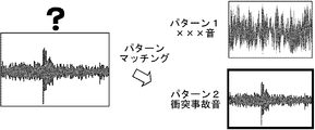
- FIG. 5 is a diagram showing an example in which the estimation unit according to the first embodiment estimates the situation of a traffic accident occurring on a road by using pattern matching.
- FIG. 5 is a diagram showing an example of vibration data used by the estimation unit according to the first embodiment to estimate the situation of a traffic accident occurring on a road.
- FIG. 5 is a diagram showing an example of vibration data used by the estimation unit according to the first embodiment to estimate the situation of a traffic accident occurring on a road.
- FIG. 5 is a diagram showing an example of vibration data used by the estimation unit according to the first embodiment to estimate the situation of a traffic accident occurring on a road.
- FIG. 5 is a diagram showing an example of vibration data used by the estimation unit according to the first embodiment to estimate the situation of a traffic accident occurring on a road.
- FIG. 5 is a diagram showing an example of a method in which the estimation unit according to the first embodiment estimates the situation of a traffic accident occurring on a road. It is a flow chart which shows the operation example of the optical fiber sensing system which concerns on Embodiment 1.
- FIG. 1 shows the operation example of the optical fiber sensing system which concerns on Embodiment 1.
- FIG. 5 is a diagram showing an example of vibration data used by the estimation unit according to the second embodiment to estimate the situation of a traffic accident occurring on a road.
- the optical fiber sensing system includes an optical fiber 10A (first optical fiber), an optical fiber 10B (second optical fiber), and an optical fiber sensing device 20. There is. Further, the optical fiber sensing device 20 includes a detection unit 21 and an estimation unit 22.
- Optical fibers 10A and 10B are laid on the road R. Specifically, the optical fiber 10A is buried in the vicinity of the road R, and the optical fiber 10B is overhead-wired along the road R. Although the optical fiber 10B is overhead-wired by the utility pole T in FIG. 1, it may be overhead-wired by other means such as a steel tower. Further, the optical fibers 10A and 10B may be realized by existing unused communication optical fibers (so-called dark fibers). Further, if the optical fibers 10A and 10B use a frequency different from the frequency used for communication in the existing communication optical fiber in use, it is realized by the existing communication optical fiber in use. May be done. Further, the optical fibers 10A and 10B may be laid on the road R in the form of an optical fiber cable configured by covering the optical fiber.
- the detection unit 21 incidents pulsed light (incident light) on the optical fiber 10A. Further, the detection unit 21 receives the reflected light or scattered light generated when the pulsed light is transmitted through the optical fiber 10A as return light (optical signal) via the optical fiber 10A. Similarly, the detection unit 21 incidents the pulsed light on the optical fiber 10B and receives the return light from the optical fiber 10B.
- the vibration When an impact is generated on the road R, the vibration is transmitted to the optical fiber 10A buried under the road R, affects the return light transmitted by the optical fiber 10A, and propagates air as sound. Therefore, it is transmitted to the optical fiber 10B which is overhead-wired along the road R, and affects the return light transmitted by the optical fiber 10B. Therefore, the optical fibers 10A and 10B can detect the vibration generated on the road R and the sound caused by the vibration.
- the impact generated on the road R propagates as vibrations through the ground and sounds through the air, but since the optical fiber 10A can easily detect the vibrations propagating on the ground, the vibrations are mainly detected. Further, since the optical fiber 10B can easily detect the sound propagating in the air, the detection is centered on the sound.
- the optical fiber 10A is not limited to this, and it is also possible to detect the vibration generated when the vehicle normally travels on the road R.
- the vibration generated on the road R has a unique vibration pattern in which the strength of the vibration, the vibration position, the transition of the fluctuation of the frequency, etc. differ depending on the event that caused the vibration.
- the vibration pattern of vibration caused by a traffic accident occurring on the road R is a pattern peculiar to the traffic accident.
- the following can be considered as the situation of a traffic accident.
- -Number of vehicles that have had a traffic accident-Type of vehicle that has had a traffic accident for example, automobiles, motorcycles, etc.
- Types of traffic accidents for example, spin accidents, rollover accidents, collision accidents, etc.
- Property damage for example, damage to traffic lights
- the detection unit 21 detects the vibration pattern of the vibration caused by the traffic accident that occurred on the road R from the return light received from the optical fibers 10A and 10B.
- the optical fiber 10A detects the vibration directly transmitted to the road R. Therefore, the detection unit 21 detects, for example, a vibration pattern of vibration caused by a traffic accident from the return light received from the optical fiber 10A.
- the optical fiber 10B detects vibration as a sound transmitted from the road R via air. Therefore, the detection unit 21 detects, for example, a vibration pattern of vibration caused by a traffic accident from the return light received from the optical fiber 10B.
- the estimation unit 22 estimates the situation of a traffic accident that occurred on the road R based on the vibration pattern of the vibration caused by the traffic accident detected by the detection unit 21. At this time, as described above, the vibration pattern of the vibration detected by the detection unit 21 becomes a pattern peculiar to a traffic accident. Therefore, the estimation unit 22 estimates the situation of a traffic accident by analyzing the dynamic change of the vibration pattern of the vibration detected by the detection unit 21.
- the return light received from the optical fibers 10A and 10B may be analyzed in real time to estimate the situation of a traffic accident, or the return light received from the optical fibers 10A and 10B may be estimated.
- the vibration data obtained by converting the light or its return light may be temporarily held, and then the return light or the vibration data may be read out and analyzed to estimate the situation of a traffic accident.
- the estimation unit 22 estimates the time of occurrence of the traffic accident based on the time when the return light in which the vibration pattern caused by the traffic accident is detected from the optical fibers 10A and 10B is received by the detection unit 21. You may.
- the estimation unit 22 detects the time when the detection unit 21 incidents the pulsed light on the optical fibers 10A and 10B and the return light from the optical fibers 10A and 10B in which the vibration pattern caused by the traffic accident is detected.
- the position where the traffic accident occurs may be estimated based on the time difference from the time received in.
- the estimation unit 22 can measure the distances of the optical fibers 10A and 10B from the detection unit 21 to the position where the traffic accident occurs based on the above time difference.
- the estimation unit 22 uses the correspondence table for traffic. It is possible to estimate the location (point) where the accident occurred.
- the estimation unit 22 will explain a specific method for estimating the situation of a traffic accident that occurred on the road R.
- the detection unit 21 converts the return light received from the optical fiber 10B into vibration data as shown in FIG. 2, for example.
- the vibration data shown in FIG. 2 is vibration data of vibration detected by the optical fiber 10B at a certain position on the road R, and the horizontal axis represents time and the vertical axis represents sound intensity.
- the estimation unit 22 estimates the situation of a traffic accident based on the vibration data as shown in FIG. At this time, for example, the estimation unit 22 uses pattern matching. Specifically, the estimation unit 22 holds in advance vibration data according to the situation of a traffic accident as teacher data. The teacher data may be learned by the estimation unit 22 by machine learning or the like. Then, as shown in FIG. 3, the estimation unit 22 compares the vibration pattern of the vibration data converted by the detection unit 21 with the vibration pattern of the plurality of teacher data held in advance. When the estimation unit 22 matches the vibration pattern of any of the teacher data, the estimation unit 22 determines that the vibration data converted by the detection unit 21 is the vibration data generated in the traffic accident situation corresponding to the matched teacher data. To do. In the example shown in FIG. 3, the vibration data converted by the detection unit 21 has a vibration pattern that substantially matches the vibration data when a collision accident occurs. Therefore, the estimation unit 22 determines that a collision accident has occurred.
- the detection unit 21 converts the return light received from the optical fiber 10A into vibration data as shown in FIGS. 4 and 5, for example.
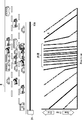
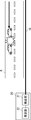
- the vibration data shown in FIGS. 4 and 5 is vibration data of vibration detected by the optical fiber 10A on the road R where two-way traffic is performed, and the horizontal axis is the distance of the optical fiber 10A from the detection unit 21 and the vertical axis is the vertical axis. However, it shows the passage of time. Further, the vertical axis becomes older data as it goes in the positive direction.
- the vibration of the vehicle traveling on the road R is detected by the optical fiber 10A, it is represented by a line that the vehicle is traveling.
- the fact that one vehicle is traveling over time is represented by a single diagonal line.
- the absolute value of the slope of the line represents the traveling speed of the vehicle. The smaller the absolute value of the slope of the line, the faster the running speed of the vehicle.
- the positive / negative of the slope of the line indicates the traveling direction of the vehicle. For example, when a positively inclined line represents a vehicle traveling in lane A, a negatively inclined line represents a vehicle traveling in lane B which is the opposite lane of lane A.
- the estimation unit 22 estimates the situation of a traffic accident based on the vibration data as shown in FIGS. 4 and 5.
- the line L1 has a negative slope, while the line L2 has a positive slope. This means that the vehicle represented by the line L1 is traveling in the opposite lane to the lane in which the vehicle represented by the line L2 is traveling. At this time, both vehicles continue to travel even after passing the position P1 where the distances of the optical fibers 10A from the detection unit 21 are the same. Therefore, in the example of FIG. 4, the estimation unit 22 determines that a traffic accident such as a collision does not occur and the vehicles are passing each other normally.
- the vehicle represented by the line L1 is traveling in the opposite lane to the lane in which the vehicle represented by the line L2 is traveling.
- both vehicles suddenly stop running without decelerating at the position P1 where the distances of the optical fibers 10A from the detection unit 21 are the same. Therefore, the estimation unit 22 determines that a head-on collision accident has occurred in the example of FIG.
- the estimation unit 22 estimates the situation of the traffic accident based on the vibration data as shown in FIGS. 4 and 5 by using the same pattern matching as the above-mentioned method A. You may.
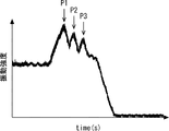
- the detection unit 21 converts the return light received from the optical fiber 10A into vibration data as shown in FIGS. 6 and 7, for example.
- the vibration data shown in FIGS. 6 and 7 focuses on a specific vehicle traveling on the road R, and shows the vibration data of the vehicle detected by the optical fiber 10A in chronological order.
- the estimation unit 22 estimates the situation of a traffic accident based on the vibration data as shown in FIGS. 6 and 7.
- the estimation unit 22 determines that a complicated form of collision accident such as a collision or a rollover of a plurality of vehicles has occurred.
- the estimation unit 22 may determine the number of vehicles in which a collision accident has occurred based on the number of peaks in the vibration data. In the example of FIG. 7, since three peaks P1 to P3 have occurred, the estimation unit 22 determines that if the collision of the peaks P1 is a collision between vehicles, a collision accident by at least four vehicles has occurred. To do.
- the estimation unit 22 estimates the situation of a traffic accident based on the vibration data as shown in FIGS. 6 and 7 by using the same pattern matching as in the above method A. Is also good.
- the above-mentioned methods A to C are examples of estimating the type of traffic accident (for example, single accident, multiple collision accident, etc.), the number of vehicles in which the traffic accident has occurred, and the like.
- the estimation unit 22 analyzes the vibration pattern, and the type of vehicle (for example, automobile, motorcycle, etc.) that caused the traffic accident, property damage (for example, damage to the traffic light, etc.), etc. May be estimated.
- the estimation unit 22 may estimate the situation of a traffic accident by using the above-mentioned methods A to C in combination with each other.
- the above-mentioned method B and method C detect the vibration directly transmitted to the road R
- the above-mentioned method A detects the vibration as the sound transmitted from the road R via the air. Therefore, for example, the estimation unit 22 analyzes the collision sound of the above-mentioned method A, determines that a dull collision sound other than the collision sound between metals is generated, and detects the time and position by the above-mentioned method C. If the impact and the sudden deceleration position of the vehicle match, it is judged that there is a possibility of personal injury when the vehicle collides with a person.
- a neural network that inputs vibration data representing a time change of amplitude as shown in FIGS. 6 and 7 is NN # 1, and the spectrum after the vibration data is subjected to Fourier conversion is shown.
- NN # 2 be the input NN
- NN # 3 be the input NN after the vibration data is Wavelet-converted
- NN # 4 be the NN representing the fusion weight of NN # 1 to NN # 3.
- the estimation unit 22 comprehensively determines the three types of information of NN # 1 to NN # 3 and estimates whether or not a traffic accident has occurred.
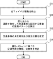
- the optical fibers 10A and 10B detect the vibration generated on the road R (step S11).
- the vibration detected by the optical fibers 10A and 10B affects the return light transmitted through the optical fibers 10A and 10B.
- the detection unit 21 detects the vibration pattern of the vibration caused by the traffic accident occurring on the road R from the return light received from the optical fibers 10A and 10B (step S12).
- the estimation unit 22 estimates the time of occurrence of the traffic accident based on the time when the return light in which the vibration pattern caused by the traffic accident is detected is received from the optical fibers 10A and 10B. Further, the estimation unit 22 has a time difference between the time when the pulsed light is incident on the optical fibers 10A and 10B and the time when the return light is received from the optical fibers 10A and 10B in which the vibration pattern caused by the traffic accident is detected. Based on the above, the position where the traffic accident occurs is estimated (step S13).
- the estimation unit 22 determines the type of traffic accident (for example, as the situation of the traffic accident occurring on the road R) based on the vibration pattern of the vibration caused by the traffic accident occurring on the road R detected by the detection unit 21. , Single accident, multiple collision accident, etc.), the number of vehicles that have caused a traffic accident, etc. are estimated (step S14).
- the optical fibers 10A and 10B detect the vibration generated on the road R.
- the detection unit 21 detects the vibration pattern of the vibration caused by the traffic accident generated on the road R from the return light received from the optical fibers 10A and 10B.
- the estimation unit 22 estimates the situation of a traffic accident that occurred on the road R based on the vibration pattern. As a result, it is possible not only to grasp whether or not a traffic accident has occurred on the road R, but also to grasp the situation of the traffic accident that has occurred on the road R.
- the optical fibers 10A and 10B can detect vibration at any place where the optical fibers 10A and 10B are laid. Therefore, it is possible to detect the occurrence of a traffic accident and grasp the situation of the traffic accident at any of the places where the optical fibers 10A and 10B are laid.
- the optical fibers 10A and 10B may be realized by existing optical fibers for communication. In this case, since it is not necessary to newly install the optical fibers 10A and 10B, the optical fiber sensing system can be constructed at low cost.
- the estimation unit 22 causes the traffic accident based on the time when the return light in which the vibration pattern caused by the traffic accident is detected is received from the optical fibers 10A and 10B. You may estimate the time. In this case, since the exact time of occurrence of the traffic accident can be grasped, it is possible to specify the display status of the traffic light at the time of occurrence of the traffic accident. As a result, even if the parties involved in the traffic accident perjury the manifestation situation, it can be determined to be perjury.
- the vibration data of the vibration detected by the optical fiber 10A and the vibration data of the vibration detected by the optical fiber 10B as sound in order to estimate the situation of the traffic accident occurring on the road R. And, but it is not limited to this.
- the detection unit 21 may convert the return light received from the optical fibers 10A and 10B into temperature data, and the estimation unit 22 may further use the temperature data to estimate the situation of a traffic accident. By using the temperature data, the estimation unit 22 can determine, for example, that the road R is frozen.
- the estimation unit 22 can determine, for example, that a fire or an explosion has occurred on the road R by using the temperature data in combination with the vibration data. Therefore, for example, when the estimation unit 22 estimates a collision accident using vibration data, the collision accident is caused by freezing of the road R or a fire or explosion occurring on the road R by further using the temperature data. It can be judged that it occurred.
- the optical fiber sensing system according to the second embodiment has the same configuration itself as the first embodiment described above, but extends the functions of the detection unit 21 and the estimation unit 22.
- the vibration pattern of the vibration generated on the road R also differs depending on the traveling state of the vehicle on the road R (for example, traveling direction, traveling speed, number of traveling vehicles, inter-vehicle distance, presence / absence of traffic jam, presence / absence of dangerous driving, etc.). .. Vibration caused by the running state of the vehicle can be detected particularly by the optical fiber 10A embedded under the road R.
- the situation of a traffic accident is estimated by using not only the vibration pattern of the vibration caused by the traffic accident occurring on the road R but also the vibration pattern of the vibration caused by the running state of the vehicle on the road R. It is something to do.
- the estimation unit 22 can specify the time and position of the traffic accident that occurred on the road R. Therefore, the detection unit 21 receives the return light received from the optical fiber 10A at the time of occurrence of the traffic accident or at least before or after the occurrence of the traffic accident, and the detection unit 21 of the vehicle near the position where the traffic accident occurs on the road R. Further detect the vibration pattern of vibration caused by the running condition.
- the estimation unit 22 uses the road R at one of the vibration pattern of the vibration caused by the traffic accident that occurred on the road R detected by the detection unit 21 and the time, before, or after the occurrence of the traffic accident.
- the situation of the traffic accident that occurred on the road R is estimated based on the vibration pattern of the vibration caused by the running state of the vehicle near the position where the above traffic accident occurred.
- the vibration pattern of the vibration detected by the detection unit 21 includes a pattern peculiar to the traffic accident and also includes a peculiar pattern according to the traveling state of the vehicle on the road R. Therefore, the estimation unit 22 estimates the situation of a traffic accident by analyzing the dynamic change of the vibration pattern of the vibration detected by the detection unit 21.
- the return light received from the optical fibers 10A and 10B or the vibration data obtained by converting the return light is temporarily held, and then the return light or the vibration data is read out and analyzed to cause a traffic accident. The situation shall be estimated.
- FIG. 10 shows the traveling state of the vehicle on the road R. Since the vibration caused by the traveling state of the vehicle is detected particularly by the optical fiber 10A, the optical fiber 10B is not shown in the upper figure of FIG. 10.
- the optical fiber 10A detects the vibration generated on the road R when the traveling state is as shown in the upper figure of FIG. 10, and the vibration affects the return light.
- the detection unit 21 receives the return light from the optical fiber 10A.
- the detection unit 21 converts the return light received from the optical fiber 10A into vibration data as shown in the lower figure of FIG. 10, for example.
- the estimation unit 22 estimates the situation of a traffic accident based on the vibration data as shown in the lower figure of FIG.
- the horizontal axis and the vertical axis of the vibration data shown in the lower figure of FIG. 10 are the same as those shown in FIGS. 4 and 5. Therefore, even in the vibration data shown in the lower figure of FIG. 10, that one vehicle is traveling on the road R with the passage of time is represented by one diagonal line.
- the absolute value of the slope of the line represents the traveling speed of the vehicle, and the positive / negative of the inclination of the line represents the traveling direction of the vehicle.
- the distance G in the horizontal axis direction of the line represents the distance between vehicles, and the shorter the distance G, the shorter the distance between vehicles.
- the plurality of lines In the vibration data shown in the lower figure of FIG. 10, in the vicinity of the center, the plurality of lines have a negative slope and a large absolute value, and the distance G between the lines is also short. This means that a plurality of vehicles are traveling in the same traveling direction, but the traveling speed is slow and the inter-vehicle distance is short. Therefore, it is considered that traffic congestion has occurred. On the other hand, it is considered that there is no congestion except near the center. In the example of the lower figure of FIG. 10, no traffic accident has occurred.
- the vibration data shown in FIG. 11 is vibration data of vibration detected by the optical fiber 10A on the road R where two-way traffic is performed.
- the four vehicles represented by the lines L1 to L4 are traveling in the same traveling direction, but the traveling speed is slow and the inter-vehicle distance is short. Therefore, it is considered that traffic congestion has occurred.
- the vehicle represented by the line L5 is traveling in the opposite lane to the lane in which the four vehicles represented by the lines L1 to L4 are traveling. Further, the vehicle represented by the line L5 has stopped traveling at the position P1 where it is considered that the traffic jam has occurred. Therefore, in the example of FIG. 11, the estimation unit 22 determines that a traffic accident has occurred in which a vehicle collides head-on from the opposite lane in a row of vehicles in which congestion has occurred.
- the estimation unit 22 utilizes the same pattern matching as the method A described in the above-described first embodiment based on the vibration data as shown in the lower figure of FIG. 10 and FIG. , You may estimate the situation of the traffic accident.
- the estimation unit 22 includes, for example, the presence / absence of a vehicle in dangerous driving (for example, tilting driving, meandering driving, reverse driving, etc.) and the presence / absence of a vehicle in which sudden braking is applied. May be estimated.
- the estimation unit 22 can determine that if there is a vehicle having a different traveling direction on the road R where one-sided traffic is performed, that vehicle is driving in the reverse direction.
- the estimation unit 22 can determine that if there is a vehicle whose traveling speed has decreased to a threshold value or more, that vehicle is suddenly braking.
- the estimation unit 22 estimates that traffic congestion has occurred after the occurrence of the traffic accident and that there is a vehicle that has escaped from the position where the traffic accident occurred by using the vibration data after the occurrence of the traffic accident. can do.
- the optical fibers 10A and 10B detect the vibration generated on the road R (step S21).
- the vibration detected by the optical fibers 10A and 10B affects the return light transmitted through the optical fibers 10A and 10B.
- the detection unit 21 detects the vibration pattern of the vibration caused by the traffic accident generated on the road R from the return light received from the optical fibers 10A and 10B (step S22).
- the estimation unit 22 estimates the occurrence time of the traffic accident based on the time when the return light in which the vibration pattern caused by the traffic accident is detected is received from the optical fibers 10A and 10B. Further, the estimation unit 22 has a time difference between the time when the pulsed light is incident on the optical fibers 10A and 10B and the time when the return light is received from the optical fibers 10A and 10B in which the vibration pattern caused by the traffic accident is detected. Based on the above, the position where the traffic accident occurs is estimated (step S23).
- the detection unit 21 is a vehicle near the position where the traffic accident occurred on the road R from the return light received from the optical fiber 10A at the time of the occurrence of the traffic accident or at least before or after the occurrence of the traffic accident.
- the vibration pattern of the vibration caused by the traveling state of is detected (step S24).
- the estimation unit 22 determines that the vibration pattern of the vibration caused by the traffic accident occurring on the road R detected by the detection unit 21 and the vibration pattern at the time of occurrence of the traffic accident or at least before or after the occurrence of the traffic accident.
- the following is estimated based on the vibration pattern of the vibration caused by the running state of the vehicle near the position where the traffic accident occurs on the road R (step S25).
- Driving conditions of vehicles near the location of the traffic accident on the road R for example, the presence or absence of traffic congestion
- Driving conditions of a specific vehicle on road R for example, tilting driving, meandering driving, reverse driving, etc.
- -Status of traffic accidents that occurred on road R for example, types of traffic accidents, number of vehicles that caused traffic accidents, etc.
- the detection unit 21 detects the vibration pattern of the vibration caused by the traffic accident occurring on the road R from the return light received from the optical fibers 10A and 10B, and also detects the vibration pattern. From the return light received from the optical fiber 10A at the time of the occurrence of the traffic accident or at least before or after the occurrence of the traffic accident, the vibration caused by the running condition of the vehicle near the position where the traffic accident occurred on the road R Detect vibration patterns.
- the estimation unit 22 estimates the situation of a traffic accident that occurred on the road R based on those vibration patterns. As a result, the situation of the traffic accident that occurred on the road R can be grasped in more detail. Other effects are the same as those in the first embodiment described above.
- the estimation unit 22 may further use the temperature data to estimate the situation of the traffic accident, as in the first embodiment described above.
- the optical fiber sensing system according to the third embodiment is different from the first embodiment described above in that the camera 30 is added. Although only one camera 30 is provided in FIG. 13, a plurality of cameras 30 may be provided.
- the camera 30 is a camera that captures the road R, and is realized by, for example, a fixed camera, a PTZ (Pan Tilt Zoom) camera, or the like.
- the estimation unit 22 defines the installation position of the camera 30 (distance of the optical fibers 10A and 10B from the detection unit 21, latitude and longitude of the installation position of the camera 30, etc.) and the position where the camera 30 can be photographed (latitude and longitude, etc.). Holds camera information indicating such as. Further, as described above, the estimation unit 22 can estimate the occurrence time and the occurrence position (distance of the optical fibers 10A and 10B from the detection unit 21) of the traffic accident that occurred on the road R.
- the estimation unit 22 estimates the time and position of the traffic accident. Then, the estimation unit 22 acquires a camera image near the position where the traffic accident occurs at the time of the occurrence of the traffic accident or at least one before or after the occurrence of the traffic accident from the camera images taken by the camera 30. However, in order to acquire a camera image near the position where the traffic accident occurs, it is necessary to convert the position where the traffic accident occurs to the position on the camera image.
- the estimation unit 22 holds in advance a correspondence table for associating the distances of the optical fibers 10A and 10B from the detection unit 21 with the camera coordinates, and even if the above-mentioned position conversion is performed using this correspondence table. good. Further, the estimation unit 22 may acquire the above-mentioned camera image from each of the plurality of cameras 30 as long as the vicinity of the position where the traffic accident occurs can be photographed by the plurality of cameras 30.
- the estimation unit 22 determines the traffic generated on the road R based on the vibration pattern of the vibration caused by the traffic accident generated on the road R detected by the detection unit 21 and the camera image acquired above. Estimate the situation of the accident.
- the estimation unit 22 estimates a collision accident or the like based on a vibration pattern of vibration caused by a traffic accident.
- the estimation unit 22 further identifies the number of the vehicle in which the collision accident or the like has occurred based on the camera image, or the occurrence of the traffic accident at the time of the occurrence of the traffic accident or at least one before or after the occurrence of the traffic accident.
- the situation of the position can be estimated.
- the situation of the position where a traffic accident occurs estimated based on the camera image is, for example, a vehicle that is driving dangerously (for example, driving ignoring traffic signs such as tilting driving, meandering driving, reverse driving, and temporary stop). Whether or not there is a vehicle, whether or not there is a vehicle driving aside or dozing, whether or not there is a traffic jam, etc.
- the return light received from the optical fibers 10A and 10B or the vibration data obtained by converting the return light and the camera image taken by the camera 30 are temporarily held, and then returned.
- the situation of the traffic accident shall be estimated by reading and analyzing the light or vibration data and the camera image.
- the estimation unit 22 may estimate the situation of the traffic accident occurring on the road R by using the NN as in the method D of the first embodiment described above. This method will be described with reference to FIG.
- NN # 1 is input as vibration data of a specific vehicle traveling on the road R and vibration data representing the correlation between the time and position of the amplitude is input, and a camera image of the road R is input.
- NN # 2 be NN
- NN # 3 be NN representing the fusion weight of NN # 1 to NN # 2.
- the estimation unit 22 comprehensively determines two types of information, NN # 1 and NN # 2, and estimates whether or not a traffic accident has occurred. For example, even if the estimation unit 22 estimates that a traffic accident has occurred based on the information of NN # 1 detected by the optical fiber 10A, if the information of NN # 2 does not show the car in the camera image, it determines that the estimation is erroneous. To do. As described above, the camera image can also be used as auxiliary information for estimating the presence or absence of a traffic accident.
- the optical fibers 10A and 10B detect the vibration generated on the road R (step S31).
- the vibration detected by the optical fibers 10A and 10B affects the return light transmitted through the optical fibers 10A and 10B.
- the detection unit 21 detects the vibration pattern of the vibration caused by the traffic accident generated on the road R from the return light received from the optical fibers 10A and 10B (step S32).
- the estimation unit 22 estimates the occurrence time of the traffic accident based on the time when the return light in which the vibration pattern caused by the traffic accident is detected is received from the optical fibers 10A and 10B. Further, the estimation unit 22 has a time difference between the time when the pulsed light is incident on the optical fibers 10A and 10B and the time when the return light is received from the optical fibers 10A and 10B in which the vibration pattern caused by the traffic accident is detected. Based on the above, the position where the traffic accident occurs is estimated (step S33).
- the estimation unit 22 acquires a camera image near the position where the traffic accident occurs at the time of the occurrence of the traffic accident or at least one before or after the occurrence of the traffic accident from the camera images taken by the camera 30 (step). S34).
- the estimation unit 22 determines the vibration pattern of the vibration caused by the traffic accident that occurred on the road R detected by the detection unit 21, and the traffic accident at the time of the occurrence of the traffic accident or at least one before or after the occurrence of the traffic accident.
- the situation of the traffic accident that occurred on the road R is estimated based on the camera image near the position where the above occurs (step S35).
- the detection unit 21 detects the vibration pattern of the vibration caused by the traffic accident occurring on the road R from the return light received from the optical fibers 10A and 10B.
- the estimation unit 22 acquires a camera image near the position where the traffic accident occurs at the time of the occurrence of the traffic accident or at least one before or after the occurrence of the traffic accident from the camera images taken by the camera 30. Then, the estimation unit 22 estimates the situation of the traffic accident that occurred on the road R based on the vibration patterns and the camera images. As a result, the situation of the traffic accident that occurred on the road R can be grasped in more detail.
- Other effects are the same as those in the first embodiment described above.
- the estimation unit 22 may acquire a camera image in the vicinity of the occurrence position after the occurrence of the traffic accident as follows. For example, when a traffic accident occurs, the estimation unit 22 controls the angle (azimuth angle, elevation angle), zoom magnification, etc. of the camera 30 so as to photograph the vicinity of the position where the traffic accident occurs, and then photographs with the camera 30. Acquire the camera image. At this time, a process of converting the position where the traffic accident occurs to the position on the camera image is required, and this position conversion may be performed by the method using the corresponding table described above.
- the present embodiment 3 has been described as having a configuration in which a function is added to the above-described first embodiment.
- the present embodiment 3 has the above-described embodiment.
- a configuration in which a function is added to the second form may be used.
- the estimation unit 22 has the vibration pattern of the vibration caused by the traffic accident that occurred on the road R detected by the detection unit 21, and the road at the time of the occurrence of the traffic accident or at least one before or after the occurrence of the traffic accident.
- the situation of the traffic accident may be estimated based on the vibration pattern of the vibration caused by the running state of the vehicle near the position where the traffic accident occurs on R and the above-mentioned camera image.
- the optical fiber sensing device 20 may further include a prediction unit 23.
- the prediction unit 23 analyzes the traveling state of the vehicle on the road R and predicts the occurrence of a traffic accident. For example, the prediction unit 23 may predict that a traffic accident will occur when a vehicle that is driving in a tilted manner, a vehicle whose traveling speed is faster than a threshold value or a vehicle that is slower than a surrounding vehicle is detected.
- the prediction unit 23 may analyze statistical data of the traveling state of the vehicle on the road R to identify a place where a traffic accident is likely to occur. For example, the prediction unit 23 may specify a place where the vehicle often suddenly brakes as a place where a traffic accident is likely to occur.
- the optical fiber sensing device 20 may further include a notification unit 24 as shown in FIG.
- the notification unit 24 When a traffic accident occurs on the road R, the notification unit 24 notifies that the traffic accident has occurred and also notifies the situation of the traffic accident estimated by the estimation unit 22. For example, if the road R is a general road, the notification unit 24 notifies the police and the fire department, and if the road R is a highway, the notification unit 24 notifies the highway management company. Further, this notification may be an acoustic output of the corresponding message or a display output.
- the notification unit 24 may determine the degree of urgency according to the situation of the traffic accident, and may change the notification destination and the content of the notification according to the determined degree of urgency. For example, the notification unit 24 may increase the degree of urgency when a person is screaming or when the number of vehicles in which a traffic accident has occurred is large. Further, as shown in Table 1, the notification unit 24 holds in advance a correspondence table in which the urgency is associated with the notification destination and the notification content, and uses the correspondence table to respond to the urgency. You may specify the notification destination and notification content. In the example of Table 1, the larger the value, the higher the urgency, and when the urgency becomes higher, the police are requested to increase the number of police cars.
- optical fiber sensing device 20 may be configured to include both the prediction unit 23 shown in FIG. 16 and the notification unit 24 shown in FIG. Further, the optical fiber sensing device 20 may be configured to be connected to the camera 30 shown in FIG.
- the optical fiber sensing device 20 is provided with a plurality of components (detection unit 21, estimation unit 22, prediction unit 23, and notification unit 24). However, it is not limited to this.
- the components provided in the optical fiber sensing device 20 are not limited to being provided in one device, and may be distributed in a plurality of devices.
- the optical fiber sensing system shown in FIG. 18 includes an optical fiber 10 and an optical fiber sensing device 20. Further, the optical fiber sensing device 20 includes a detection unit 21 and an estimation unit 22.
- the optical fiber 10 is provided along the road R and detects vibration.
- the optical fiber 10 may be provided in the vicinity of the road R or may be laid on the road R. Further, the optical fiber 10 may be buried under the road R or may be overhead-wired.
- the detection unit 21 incidents pulsed light on the optical fiber 10 and receives reflected light or scattered light generated as the pulsed light is transmitted through the optical fiber 10 as return light via the optical fiber 10. .. Further, the detection unit 21 detects the vibration pattern of the vibration caused by the traffic accident generated on the road R from the optical signal received from the optical fiber 10.
- the estimation unit 22 estimates the situation of a traffic accident that occurred on the road R based on the vibration pattern of the vibration caused by the traffic accident detected by the detection unit 21.
- the optical fiber 10 detects the vibration generated on the road R (step S41).
- the vibration detected by the optical fiber 10 affects the return light transmitted through the optical fiber 10.
- the detection unit 21 detects the vibration pattern of the vibration caused by the traffic accident occurring on the road R from the return light received from the optical fiber 10 (step S42). After that, the estimation unit 22 estimates the situation of the traffic accident occurring on the road R based on the vibration pattern of the vibration caused by the traffic accident occurring on the road R detected by the detection unit 21 (step S43).
- the computer 40 includes a processor 401, a memory 402, a storage 403, an input / output interface (input / output I / F) 404, a communication interface (communication I / F) 405, and the like.
- the processor 401, the memory 402, the storage 403, the input / output interface 404, and the communication interface 405 are connected by a data transmission line for transmitting and receiving data to and from each other.
- the processor 401 is, for example, an arithmetic processing unit such as a CPU (Central Processing Unit) or a GPU (Graphics Processing Unit).
- the memory 402 is, for example, a memory such as a RAM (Random Access Memory) or a ROM (Read Only Memory).
- the storage 403 is, for example, a storage device such as an HDD (Hard Disk Drive), an SSD (Solid State Drive), or a memory card. Further, the storage 403 may be a memory such as a RAM or a ROM.
- the storage 403 stores a program that realizes the functions of the components (detection unit 21 and estimation unit 22) included in the optical fiber sensing device 20. By executing each of these programs, the processor 401 realizes the functions of the components included in the optical fiber sensing device 20. Here, when executing each of the above programs, the processor 401 may read these programs onto the memory 402 and then execute the programs, or may execute the programs without reading them onto the memory 402. The memory 402 and the storage 403 also play a role of storing information and data held by the components included in the optical fiber sensing device 20.
- Non-temporary computer-readable media include various types of tangible storage media.
- Examples of non-temporary computer-readable media include magnetic recording media (eg, flexible disks, magnetic tapes, hard disk drives), magneto-optical recording media (eg, magneto-optical disks), CD-ROMs (Compact Disc-ROMs), CDs. -R (CD-Recordable), CD-R / W (CD-ReWritable), semiconductor memory (for example, mask ROM, PROM (Programmable ROM), EPROM (Erasable PROM), flash ROM, RAM.
- the program also includes.
- the computer-readable medium can supply the program to the computer via a wired communication path such as an electric wire and an optical fiber, or a wireless communication path.
- the input / output interface 404 is connected to a display device 4041, an input device 4042, a sound output device 4043, and the like.
- the display device 4041 is a device that displays a screen corresponding to drawing data processed by the processor 401, such as an LCD (Liquid Crystal Display), a CRT (Cathode Ray Tube) display, and a monitor.
- the input device 4042 is a device that receives an operator's operation input, and is, for example, a keyboard, a mouse, a touch sensor, and the like.
- the display device 4041 and the input device 4042 may be integrated and realized as a touch panel.
- the sound output device 4043 is a device such as a speaker that acoustically outputs sound corresponding to acoustic data processed by the processor 401.
- the communication interface 405 sends and receives data to and from an external device.
- the communication interface 405 communicates with an external device via a wired communication path or a wireless communication path.
- Appendix 1 An optical fiber installed along the road to detect vibration, From the optical signal received from the optical fiber, a detection unit that detects the vibration pattern of vibration caused by a traffic accident occurring on the road, and An estimation unit that estimates the situation of the traffic accident based on the vibration pattern, An optical fiber sensing system.
- Appendix 2 The estimation unit estimates the time of occurrence of the traffic accident based on the time when the optical signal in which the vibration pattern is detected is received from the optical fiber.
- the optical fiber sensing system according to Appendix 1.
- Appendix 3 The detection unit receives the optical signal with respect to the incident light incident on the optical fiber, and receives the optical signal.
- the estimation unit determines the traffic accident based on the time difference between the time when the incident light is incident on the optical fiber and the time when the optical signal in which the vibration pattern is detected is received from the optical fiber. Estimate the position of occurrence of The optical fiber sensing system according to Appendix 2. (Appendix 4) The vibration pattern further includes a vibration pattern of vibration caused by a running state of a vehicle near the position where the traffic accident occurs on the road at the time of occurrence or before the occurrence of the traffic accident. The estimation unit estimates the situation of the traffic accident based on the vibration pattern.
- the optical fiber sensing system according to Appendix 3.
- the vibration pattern further includes a vibration pattern of vibration caused by a running state of a vehicle near the position where the traffic accident occurs on the road after the occurrence of the traffic accident.
- the estimation unit estimates the situation of the traffic accident based on the vibration pattern.
- the optical fiber sensing system according to Appendix 3 or 4. (Appendix 6) Further equipped with a camera to shoot the road The estimation unit From the camera images taken by the camera, a camera image near the position where the traffic accident occurred on the road at the time of the occurrence of the traffic accident, before, or after the occurrence of the traffic accident is acquired. , The situation of the traffic accident is estimated based on the vibration pattern and the acquired camera image.
- the optical fiber sensing system according to Appendix 3.
- the optical fiber sensing system according to Appendix 4 or 5.
- the optical fiber is The first optical fiber buried under the road and A second optical fiber that is overhead wired along the road, The optical fiber sensing system according to any one of Appendix 1 to 7, comprising the above.
- Appendix 9 It is a road monitoring method using an optical fiber sensing system.
- An optical fiber installed along the road detects vibration, A detection step for detecting a vibration pattern of vibration caused by a traffic accident occurring on the road from an optical signal received from the optical fiber, and a detection step.
- the time of occurrence of the traffic accident is estimated based on the time when the optical signal in which the vibration pattern is detected is received from the optical fiber.
- the road monitoring method described in Appendix 9. (Appendix 11)
- the detection step the optical signal for the incident light incident on the optical fiber is received, and the light signal is received.
- the traffic accident is based on the time difference between the time when the incident light is incident on the optical fiber and the time when the optical signal in which the vibration pattern is detected is received from the optical fiber.
- Estimate the position of occurrence of The road monitoring method according to Appendix 10.
- the vibration pattern further includes a vibration pattern of vibration caused by a running state of a vehicle near the position where the traffic accident occurs on the road at the time of occurrence or before the occurrence of the traffic accident.
- the situation of the traffic accident is estimated based on the vibration pattern.
- the vibration pattern further includes a vibration pattern of vibration caused by a running state of a vehicle near the position where the traffic accident occurs on the road after the occurrence of the traffic accident.
- the situation of the traffic accident is estimated based on the vibration pattern.
- the road monitoring method according to Appendix 11 or 12.
- Appendix 14 In the estimation step, From the camera images taken by the camera that photographs the road, a camera near the position where the traffic accident occurs on the road at the time of the occurrence of the traffic accident, before, or after the occurrence of the traffic accident. Get the image, The situation of the traffic accident is estimated based on the vibration pattern and the acquired camera image.
- a detection unit that detects the vibration pattern of vibration caused by a traffic accident that occurred on the road from an optical signal that is provided along the road and is received from an optical fiber that detects vibration.
- An estimation unit that estimates the situation of the traffic accident based on the vibration pattern,
- the estimation unit estimates the time of occurrence of the traffic accident based on the time when the optical signal in which the vibration pattern is detected is received from the optical fiber.
- the optical fiber sensing device according to Appendix 17.
- the detection unit receives the optical signal with respect to the incident light incident on the optical fiber, and receives the optical signal.
- the estimation unit determines the traffic accident based on the time difference between the time when the incident light is incident on the optical fiber and the time when the optical signal in which the vibration pattern is detected is received from the optical fiber. Estimate the position of occurrence of The optical fiber sensing device according to Appendix 18. (Appendix 20)
- the vibration pattern further includes a vibration pattern of vibration caused by a running state of a vehicle near the position where the traffic accident occurs on the road at the time of occurrence or before the occurrence of the traffic accident.
- the estimation unit estimates the situation of the traffic accident based on the vibration pattern.
- the optical fiber sensing device according to Appendix 19.
- the vibration pattern further includes a vibration pattern of vibration caused by a running state of a vehicle near the position where the traffic accident occurs on the road after the occurrence of the traffic accident.
- the estimation unit estimates the situation of the traffic accident based on the vibration pattern.
- the optical fiber sensing device according to Appendix 19 or 20.
- the estimation unit From the camera images taken by the camera that photographs the road, a camera near the position where the traffic accident occurs on the road at the time of the occurrence of the traffic accident, before, or after the occurrence of the traffic accident. Get the image, The situation of the traffic accident is estimated based on the vibration pattern and the acquired camera image.
- the optical fiber sensing device according to Appendix 19.
- the estimation unit From the camera images taken by the camera that photographs the road, a camera near the position where the traffic accident occurs on the road at the time of the occurrence of the traffic accident, before, or after the occurrence of the traffic accident. Get the image, The situation of the traffic accident is estimated based on the vibration pattern and the acquired camera image.
- the optical fiber sensing device according to Appendix 20 or 21.
Landscapes
- Physics & Mathematics (AREA)
- General Physics & Mathematics (AREA)
- Chemical & Material Sciences (AREA)
- Analytical Chemistry (AREA)
- Engineering & Computer Science (AREA)
- Multimedia (AREA)
- Theoretical Computer Science (AREA)
- Traffic Control Systems (AREA)
Priority Applications (4)
| Application Number | Priority Date | Filing Date | Title |
|---|---|---|---|
| US17/635,533 US20220327923A1 (en) | 2019-08-26 | 2019-08-26 | Optical fiber sensing system, road monitoring method, and optical fiber sensing device |
| PCT/JP2019/033368 WO2021038695A1 (ja) | 2019-08-26 | 2019-08-26 | 光ファイバセンシングシステム、道路監視方法、及び光ファイバセンシング機器 |
| JP2021541820A JP7188604B2 (ja) | 2019-08-26 | 2019-08-26 | 光ファイバセンシングシステム、道路監視方法、及び光ファイバセンシング機器 |
| JP2022190950A JP7332020B2 (ja) | 2019-08-26 | 2022-11-30 | 光ファイバセンシングシステム、道路監視方法、及び光ファイバセンシング機器 |
Applications Claiming Priority (1)
| Application Number | Priority Date | Filing Date | Title |
|---|---|---|---|
| PCT/JP2019/033368 WO2021038695A1 (ja) | 2019-08-26 | 2019-08-26 | 光ファイバセンシングシステム、道路監視方法、及び光ファイバセンシング機器 |
Publications (1)
| Publication Number | Publication Date |
|---|---|
| WO2021038695A1 true WO2021038695A1 (ja) | 2021-03-04 |
Family
ID=74685367
Family Applications (1)
| Application Number | Title | Priority Date | Filing Date |
|---|---|---|---|
| PCT/JP2019/033368 Ceased WO2021038695A1 (ja) | 2019-08-26 | 2019-08-26 | 光ファイバセンシングシステム、道路監視方法、及び光ファイバセンシング機器 |
Country Status (3)
| Country | Link |
|---|---|
| US (1) | US20220327923A1 (https=) |
| JP (2) | JP7188604B2 (https=) |
| WO (1) | WO2021038695A1 (https=) |
Cited By (4)
| Publication number | Priority date | Publication date | Assignee | Title |
|---|---|---|---|---|
| WO2022185922A1 (ja) * | 2021-03-04 | 2022-09-09 | 日本電気株式会社 | 交通監視装置、交通監視システム、交通監視方法及びプログラム |
| WO2022215246A1 (ja) * | 2021-04-09 | 2022-10-13 | 日本電気株式会社 | 道路監視システム、道路監視装置、道路監視方法、及び非一時的なコンピュータ可読媒体 |
| WO2023053179A1 (ja) * | 2021-09-28 | 2023-04-06 | 日本電気株式会社 | 光ファイバセンシングシステム、光ファイバセンシング機器、及び道路監視方法 |
| WO2024201664A1 (ja) * | 2023-03-27 | 2024-10-03 | 日本電気株式会社 | 監視システム、監視装置、及び監視方法 |
Families Citing this family (6)
| Publication number | Priority date | Publication date | Assignee | Title |
|---|---|---|---|---|
| JP7424394B2 (ja) * | 2020-01-31 | 2024-01-30 | 日本電気株式会社 | 車両監視システム、車両監視方法、及び車両監視装置 |
| CN113838300A (zh) * | 2021-09-26 | 2021-12-24 | 武汉理工大学 | 一种高速公路突发事故无盲区实时监测与报警系统 |
| WO2024176278A1 (ja) * | 2023-02-20 | 2024-08-29 | 日本電信電話株式会社 | 道路の振動を解析する装置及び方法 |
| WO2024176277A1 (ja) * | 2023-02-20 | 2024-08-29 | 日本電信電話株式会社 | 道路の振動を解析する装置及び方法 |
| WO2025085129A1 (en) * | 2023-10-17 | 2025-04-24 | Nec Laboratories America, Inc. | Separating temperature and traffic information from complex dfos data |
| CN117858318B (zh) * | 2024-03-08 | 2024-05-07 | 四川九通智路科技有限公司 | 一种公路隧道灯光调节方法及调节系统 |
Citations (3)
| Publication number | Priority date | Publication date | Assignee | Title |
|---|---|---|---|---|
| JPH1069594A (ja) * | 1996-08-28 | 1998-03-10 | Toyota Motor Corp | 車両事故検出装置 |
| JP2004252520A (ja) * | 2003-02-18 | 2004-09-09 | Sumitomo Electric Ind Ltd | 道路監視システム |
| JP2009075000A (ja) * | 2007-09-21 | 2009-04-09 | Furukawa Electric Co Ltd:The | 光ファイバによる振動・衝撃位置検知装置 |
Family Cites Families (5)
| Publication number | Priority date | Publication date | Assignee | Title |
|---|---|---|---|---|
| CN104700624B (zh) | 2015-03-16 | 2017-07-07 | 电子科技大学 | 基于相敏光时域反射仪的车流量在线监测系统的监测方法 |
| GB201519202D0 (en) * | 2015-10-30 | 2015-12-16 | Optasense Holdings Ltd | Monitoring traffic flow |
| CN107591002B (zh) * | 2017-09-21 | 2020-06-02 | 电子科技大学 | 一种基于分布式光纤的高速公路交通参数实时估计方法 |
| MX2021006517A (es) | 2018-12-03 | 2021-11-04 | Nec Corp | Sistema de monitoreo de carreteras, dispositivo de monitoreo de carreteras, metodo de monitoreo de carreteras y medio no transitorio legible por computadora. |
| WO2020161823A1 (ja) * | 2019-02-06 | 2020-08-13 | 日本電気株式会社 | 光ファイバセンシングシステム、監視装置、監視方法、及びコンピュータ可読媒体 |
-
2019
- 2019-08-26 JP JP2021541820A patent/JP7188604B2/ja active Active
- 2019-08-26 US US17/635,533 patent/US20220327923A1/en not_active Abandoned
- 2019-08-26 WO PCT/JP2019/033368 patent/WO2021038695A1/ja not_active Ceased
-
2022
- 2022-11-30 JP JP2022190950A patent/JP7332020B2/ja active Active
Patent Citations (3)
| Publication number | Priority date | Publication date | Assignee | Title |
|---|---|---|---|---|
| JPH1069594A (ja) * | 1996-08-28 | 1998-03-10 | Toyota Motor Corp | 車両事故検出装置 |
| JP2004252520A (ja) * | 2003-02-18 | 2004-09-09 | Sumitomo Electric Ind Ltd | 道路監視システム |
| JP2009075000A (ja) * | 2007-09-21 | 2009-04-09 | Furukawa Electric Co Ltd:The | 光ファイバによる振動・衝撃位置検知装置 |
Cited By (6)
| Publication number | Priority date | Publication date | Assignee | Title |
|---|---|---|---|---|
| WO2022185922A1 (ja) * | 2021-03-04 | 2022-09-09 | 日本電気株式会社 | 交通監視装置、交通監視システム、交通監視方法及びプログラム |
| WO2022215246A1 (ja) * | 2021-04-09 | 2022-10-13 | 日本電気株式会社 | 道路監視システム、道路監視装置、道路監視方法、及び非一時的なコンピュータ可読媒体 |
| US12347311B2 (en) | 2021-04-09 | 2025-07-01 | Nec Corporation | Road monitoring system, road monitoring device, and road monitoring method |
| WO2023053179A1 (ja) * | 2021-09-28 | 2023-04-06 | 日本電気株式会社 | 光ファイバセンシングシステム、光ファイバセンシング機器、及び道路監視方法 |
| JPWO2023053179A1 (https=) * | 2021-09-28 | 2023-04-06 | ||
| WO2024201664A1 (ja) * | 2023-03-27 | 2024-10-03 | 日本電気株式会社 | 監視システム、監視装置、及び監視方法 |
Also Published As
| Publication number | Publication date |
|---|---|
| US20220327923A1 (en) | 2022-10-13 |
| JP7188604B2 (ja) | 2022-12-13 |
| JPWO2021038695A1 (https=) | 2021-03-04 |
| JP7332020B2 (ja) | 2023-08-23 |
| JP2023014212A (ja) | 2023-01-26 |
Similar Documents
| Publication | Publication Date | Title |
|---|---|---|
| JP7332020B2 (ja) | 光ファイバセンシングシステム、道路監視方法、及び光ファイバセンシング機器 | |
| JP2023184539A (ja) | 道路監視システム、道路監視装置、道路監視方法、及びプログラム | |
| KR20190115040A (ko) | 운전 거동 결정 방법, 디바이스, 장비 및 저장 매체 | |
| EP3227874A1 (en) | Driving determination device and detection device | |
| JP5627531B2 (ja) | 運転支援装置 | |
| CN114530057B (zh) | 一种车辆预警方法、装置、车辆及存储介质 | |
| JP7424394B2 (ja) | 車両監視システム、車両監視方法、及び車両監視装置 | |
| JP7044382B2 (ja) | 運転支援装置、方法、プログラム及びシステム | |
| CN116507540A (zh) | 风险管理装置、风险管理方法及风险管理系统 | |
| JP2007310574A (ja) | 衝突危険性判定システム及び警告システム | |
| KR101266015B1 (ko) | 승강장 안전선 및 선로 감시 시스템 | |
| WO2024239371A1 (zh) | 一种基于电单车头盔侦测处理交通事故的方法及电单车 | |
| KR20210156475A (ko) | 터널 사고 감지시스템 및 이를 이용한 터널 사고 판단방법 | |
| CN216527544U (zh) | 一种收费站车道安全预警装置 | |
| CN116453375A (zh) | 城市道路危险数据监控管理方法、装置、电子设备及介质 | |
| JP7473008B2 (ja) | 判定システム、サーバ、判定方法、及び判定プログラム | |
| US20240393163A1 (en) | Optical fiber sensing system, optical fiber sensing device, and road monitoring method | |
| WO2016088375A1 (en) | Driving determination device and detection device | |
| CN118722612B (zh) | 车辆防护机罩控制方法、装置、设备及存储介质 | |
| KR101971262B1 (ko) | 통행 예측을 기반으로 한 사고 관리 방법 및 시스템 | |
| JP2021157595A (ja) | 走行支援システム、走行支援方法およびプログラム | |
| US20260120562A1 (en) | Method and system for recognizing traffic accident, and computer-readable storage medium | |
| JP7484528B2 (ja) | 警告提示制御装置、警告提示制御システム、警告提示制御方法、及び、警告提示制御プログラム | |
| KR20260000070A (ko) | 도로 스마트 모니터링 장치와, 서버 및 운용 방법 | |
| JP2026011264A (ja) | 交通監視装置、交通監視システム、交通監視方法、及びプログラム |
Legal Events
| Date | Code | Title | Description |
|---|---|---|---|
| 121 | Ep: the epo has been informed by wipo that ep was designated in this application |
Ref document number: 19943613 Country of ref document: EP Kind code of ref document: A1 |
|
| ENP | Entry into the national phase |
Ref document number: 2021541820 Country of ref document: JP Kind code of ref document: A |
|
| NENP | Non-entry into the national phase |
Ref country code: DE |
|
| 122 | Ep: pct application non-entry in european phase |
Ref document number: 19943613 Country of ref document: EP Kind code of ref document: A1 |