WO2021033564A1 - 静翼、及びこれを備えているガスタービン - Google Patents
静翼、及びこれを備えているガスタービン Download PDFInfo
- Publication number
- WO2021033564A1 WO2021033564A1 PCT/JP2020/030187 JP2020030187W WO2021033564A1 WO 2021033564 A1 WO2021033564 A1 WO 2021033564A1 JP 2020030187 W JP2020030187 W JP 2020030187W WO 2021033564 A1 WO2021033564 A1 WO 2021033564A1
- Authority
- WO
- WIPO (PCT)
- Prior art keywords
- end surface
- air passage
- pressure side
- negative pressure
- shroud
- Prior art date
- Legal status (The legal status is an assumption and is not a legal conclusion. Google has not performed a legal analysis and makes no representation as to the accuracy of the status listed.)
- Ceased
Links
Images


Classifications
-
- F—MECHANICAL ENGINEERING; LIGHTING; HEATING; WEAPONS; BLASTING
- F16—ENGINEERING ELEMENTS AND UNITS; GENERAL MEASURES FOR PRODUCING AND MAINTAINING EFFECTIVE FUNCTIONING OF MACHINES OR INSTALLATIONS; THERMAL INSULATION IN GENERAL
- F16J—PISTONS; CYLINDERS; SEALINGS
- F16J15/00—Sealings
- F16J15/44—Free-space packings
- F16J15/447—Labyrinth packings
- F16J15/4476—Labyrinth packings with radial path
-
- F—MECHANICAL ENGINEERING; LIGHTING; HEATING; WEAPONS; BLASTING
- F02—COMBUSTION ENGINES; HOT-GAS OR COMBUSTION-PRODUCT ENGINE PLANTS
- F02C—GAS-TURBINE PLANTS; AIR INTAKES FOR JET-PROPULSION PLANTS; CONTROLLING FUEL SUPPLY IN AIR-BREATHING JET-PROPULSION PLANTS
- F02C7/00—Features, components parts, details or accessories, not provided for in, or of interest apart form groups F02C1/00 - F02C6/00; Air intakes for jet-propulsion plants
- F02C7/12—Cooling of plants
- F02C7/16—Cooling of plants characterised by cooling medium
- F02C7/18—Cooling of plants characterised by cooling medium the medium being gaseous, e.g. air
-
- F—MECHANICAL ENGINEERING; LIGHTING; HEATING; WEAPONS; BLASTING
- F01—MACHINES OR ENGINES IN GENERAL; ENGINE PLANTS IN GENERAL; STEAM ENGINES
- F01D—NON-POSITIVE DISPLACEMENT MACHINES OR ENGINES, e.g. STEAM TURBINES
- F01D11/00—Preventing or minimising internal leakage of working-fluid, e.g. between stages
-
- F—MECHANICAL ENGINEERING; LIGHTING; HEATING; WEAPONS; BLASTING
- F01—MACHINES OR ENGINES IN GENERAL; ENGINE PLANTS IN GENERAL; STEAM ENGINES
- F01D—NON-POSITIVE DISPLACEMENT MACHINES OR ENGINES, e.g. STEAM TURBINES
- F01D25/00—Component parts, details, or accessories, not provided for in, or of interest apart from, other groups
- F01D25/08—Cooling; Heating; Heat-insulation
- F01D25/12—Cooling
-
- F—MECHANICAL ENGINEERING; LIGHTING; HEATING; WEAPONS; BLASTING
- F01—MACHINES OR ENGINES IN GENERAL; ENGINE PLANTS IN GENERAL; STEAM ENGINES
- F01D—NON-POSITIVE DISPLACEMENT MACHINES OR ENGINES, e.g. STEAM TURBINES
- F01D5/00—Blades; Blade-carrying members; Heating, heat-insulating, cooling or antivibration means on the blades or the members
- F01D5/12—Blades
- F01D5/14—Form or construction
- F01D5/18—Hollow blades, i.e. blades with cooling or heating channels or cavities; Heating, heat-insulating or cooling means on blades
- F01D5/186—Film cooling
-
- F—MECHANICAL ENGINEERING; LIGHTING; HEATING; WEAPONS; BLASTING
- F01—MACHINES OR ENGINES IN GENERAL; ENGINE PLANTS IN GENERAL; STEAM ENGINES
- F01D—NON-POSITIVE DISPLACEMENT MACHINES OR ENGINES, e.g. STEAM TURBINES
- F01D9/00—Stators
- F01D9/02—Nozzles; Nozzle boxes; Stator blades; Guide conduits, e.g. individual nozzles
-
- F—MECHANICAL ENGINEERING; LIGHTING; HEATING; WEAPONS; BLASTING
- F01—MACHINES OR ENGINES IN GENERAL; ENGINE PLANTS IN GENERAL; STEAM ENGINES
- F01D—NON-POSITIVE DISPLACEMENT MACHINES OR ENGINES, e.g. STEAM TURBINES
- F01D9/00—Stators
- F01D9/06—Fluid supply conduits to nozzles or the like
-
- F—MECHANICAL ENGINEERING; LIGHTING; HEATING; WEAPONS; BLASTING
- F01—MACHINES OR ENGINES IN GENERAL; ENGINE PLANTS IN GENERAL; STEAM ENGINES
- F01D—NON-POSITIVE DISPLACEMENT MACHINES OR ENGINES, e.g. STEAM TURBINES
- F01D9/00—Stators
- F01D9/06—Fluid supply conduits to nozzles or the like
- F01D9/065—Fluid supply or removal conduits traversing the working fluid flow, e.g. for lubrication-, cooling-, or sealing fluids
-
- F—MECHANICAL ENGINEERING; LIGHTING; HEATING; WEAPONS; BLASTING
- F02—COMBUSTION ENGINES; HOT-GAS OR COMBUSTION-PRODUCT ENGINE PLANTS
- F02C—GAS-TURBINE PLANTS; AIR INTAKES FOR JET-PROPULSION PLANTS; CONTROLLING FUEL SUPPLY IN AIR-BREATHING JET-PROPULSION PLANTS
- F02C3/00—Gas-turbine plants characterised by the use of combustion products as the working fluid
- F02C3/14—Gas-turbine plants characterised by the use of combustion products as the working fluid characterised by the arrangement of the combustion chamber in the plant
-
- F—MECHANICAL ENGINEERING; LIGHTING; HEATING; WEAPONS; BLASTING
- F02—COMBUSTION ENGINES; HOT-GAS OR COMBUSTION-PRODUCT ENGINE PLANTS
- F02C—GAS-TURBINE PLANTS; AIR INTAKES FOR JET-PROPULSION PLANTS; CONTROLLING FUEL SUPPLY IN AIR-BREATHING JET-PROPULSION PLANTS
- F02C7/00—Features, components parts, details or accessories, not provided for in, or of interest apart form groups F02C1/00 - F02C6/00; Air intakes for jet-propulsion plants
- F02C7/28—Arrangement of seals
-
- F—MECHANICAL ENGINEERING; LIGHTING; HEATING; WEAPONS; BLASTING
- F16—ENGINEERING ELEMENTS AND UNITS; GENERAL MEASURES FOR PRODUCING AND MAINTAINING EFFECTIVE FUNCTIONING OF MACHINES OR INSTALLATIONS; THERMAL INSULATION IN GENERAL
- F16J—PISTONS; CYLINDERS; SEALINGS
- F16J15/00—Sealings
- F16J15/02—Sealings between relatively-stationary surfaces
-
- F—MECHANICAL ENGINEERING; LIGHTING; HEATING; WEAPONS; BLASTING
- F16—ENGINEERING ELEMENTS AND UNITS; GENERAL MEASURES FOR PRODUCING AND MAINTAINING EFFECTIVE FUNCTIONING OF MACHINES OR INSTALLATIONS; THERMAL INSULATION IN GENERAL
- F16J—PISTONS; CYLINDERS; SEALINGS
- F16J15/00—Sealings
- F16J15/44—Free-space packings
- F16J15/447—Labyrinth packings
-
- F—MECHANICAL ENGINEERING; LIGHTING; HEATING; WEAPONS; BLASTING
- F05—INDEXING SCHEMES RELATING TO ENGINES OR PUMPS IN VARIOUS SUBCLASSES OF CLASSES F01-F04
- F05D—INDEXING SCHEME FOR ASPECTS RELATING TO NON-POSITIVE-DISPLACEMENT MACHINES OR ENGINES, GAS-TURBINES OR JET-PROPULSION PLANTS
- F05D2220/00—Application
- F05D2220/30—Application in turbines
- F05D2220/32—Application in turbines in gas turbines
-
- F—MECHANICAL ENGINEERING; LIGHTING; HEATING; WEAPONS; BLASTING
- F05—INDEXING SCHEMES RELATING TO ENGINES OR PUMPS IN VARIOUS SUBCLASSES OF CLASSES F01-F04
- F05D—INDEXING SCHEME FOR ASPECTS RELATING TO NON-POSITIVE-DISPLACEMENT MACHINES OR ENGINES, GAS-TURBINES OR JET-PROPULSION PLANTS
- F05D2240/00—Components
- F05D2240/55—Seals
-
- F—MECHANICAL ENGINEERING; LIGHTING; HEATING; WEAPONS; BLASTING
- F05—INDEXING SCHEMES RELATING TO ENGINES OR PUMPS IN VARIOUS SUBCLASSES OF CLASSES F01-F04
- F05D—INDEXING SCHEME FOR ASPECTS RELATING TO NON-POSITIVE-DISPLACEMENT MACHINES OR ENGINES, GAS-TURBINES OR JET-PROPULSION PLANTS
- F05D2240/00—Components
- F05D2240/80—Platforms for stationary or moving blades
- F05D2240/81—Cooled platforms
-
- F—MECHANICAL ENGINEERING; LIGHTING; HEATING; WEAPONS; BLASTING
- F05—INDEXING SCHEMES RELATING TO ENGINES OR PUMPS IN VARIOUS SUBCLASSES OF CLASSES F01-F04
- F05D—INDEXING SCHEME FOR ASPECTS RELATING TO NON-POSITIVE-DISPLACEMENT MACHINES OR ENGINES, GAS-TURBINES OR JET-PROPULSION PLANTS
- F05D2250/00—Geometry
- F05D2250/10—Two-dimensional
- F05D2250/18—Two-dimensional patterned
- F05D2250/185—Two-dimensional patterned serpentine-like
-
- F—MECHANICAL ENGINEERING; LIGHTING; HEATING; WEAPONS; BLASTING
- F05—INDEXING SCHEMES RELATING TO ENGINES OR PUMPS IN VARIOUS SUBCLASSES OF CLASSES F01-F04
- F05D—INDEXING SCHEME FOR ASPECTS RELATING TO NON-POSITIVE-DISPLACEMENT MACHINES OR ENGINES, GAS-TURBINES OR JET-PROPULSION PLANTS
- F05D2260/00—Function
- F05D2260/20—Heat transfer, e.g. cooling
- F05D2260/201—Heat transfer, e.g. cooling by impingement of a fluid
-
- F—MECHANICAL ENGINEERING; LIGHTING; HEATING; WEAPONS; BLASTING
- F05—INDEXING SCHEMES RELATING TO ENGINES OR PUMPS IN VARIOUS SUBCLASSES OF CLASSES F01-F04
- F05D—INDEXING SCHEME FOR ASPECTS RELATING TO NON-POSITIVE-DISPLACEMENT MACHINES OR ENGINES, GAS-TURBINES OR JET-PROPULSION PLANTS
- F05D2260/00—Function
- F05D2260/20—Heat transfer, e.g. cooling
- F05D2260/202—Heat transfer, e.g. cooling by film cooling
Definitions
- the present invention relates to a stationary blade and a gas turbine including the blade.
- the present application claims priority based on Japanese Patent Application No. 2019-149245 filed in Japan on August 16, 2019, the contents of which are incorporated herein by reference.
- the gas turbine includes a compressor that compresses air to generate compressed air, a combustor that burns fuel in compressed air to generate fuel gas, and a turbine driven by combustion gas.
- the turbine includes a turbine rotor that rotates about an axis, a turbine casing that covers the rotor, and a plurality of vane trains.
- the turbine rotor has a rotor shaft centered on an axis and a plurality of blade rows attached to the rotor shaft.
- the plurality of blade rows are arranged in the axial direction in which the axis extends.
- Each blade row has a plurality of blades arranged in the circumferential direction with respect to the axis.
- a plurality of vane rows are arranged in the axial direction and attached to the inner peripheral side of the turbine casing.
- Each of the plurality of blade rows is arranged on the upstream side of the axis of any one of the plurality of blade rows.
- Each vane row has a plurality of vanes aligned in the circumferential direction with respect to the axis.
- a stationary blade includes a blade body that extends radially with respect to the axis to form an airfoil, an inner shroud provided on the radial inner side of the blade body, and an outer shroud provided on the radial outer side of the blade body.
- the blade body of the stationary blade is arranged in the combustion gas flow path through which the combustion gas passes.
- the inner shroud defines the radial inner edge of the combustion gas flow path.
- the outer shroud defines the radial outer edge of the combustion gas flow path.
- the stationary blades of gas turbines are exposed to high temperature combustion gas. Therefore, the stationary blade is generally cooled by air or the like.
- the inner shroud of the stationary blade described in Patent Document 1 below is formed with a cooling air passage through which cooling air passes.
- the inner shroud has a gas path surface facing outward in the radial direction, an anti-gas path surface facing inward in the radial direction, and a front end surface facing upstream of the axis.
- the gas path surface is exposed to combustion gas.
- the front end face may come into contact with combustion gas.
- the anti-gas path surface is in contact with the compressed air from the compressed air.
- the cooling air passage has an inlet that is open on the anti-gas path surface and an outlet that is open on the front end surface. Compressed air flows into the cooling air passage as cooling air from the inlet. This cooling air cools the gas path surface in the process of passing through the cooling air passage. This cooling air flows out from the outlet formed on the front end face.
- an object of the present invention is to provide a stationary blade capable of efficiently cooling and a gas turbine provided with the stationary blade.
- the first air passage has a first inlet that is open at the cavity defining surface and a first outlet that is open at the front end corner.
- the second air passage has a second inlet that is open at the cavity defining surface and a second outlet that is open at the front end surface.
- a part of the cooling air that has flowed into the cavity flows into the first air passage from the first inlet.
- the other part of the cooling air that has flowed into the cavity flows into the second air passage from the second inlet.
- the cooling air flowing into the first air passage convection-cools the upstream part of the shroud, particularly the upstream part of the gas path surface in the process of passing through the first air passage.
- the cooling air flows out into the combustion gas flow path from the first outlet formed at the front end corner.
- the cooling air flowing out into the combustion gas flow path suppresses the combustion gas from reaching the front end corner, thereby suppressing the heating of the front end corner by the combustion gas. Further, the cooling air flowing out into the combustion gas flow path suppresses the combustion gas from flowing into the gap space between the tail tube and the shroud, and lowers the temperature of the gas flowing into the gap space.
- the cooling air that has flowed into the second air passage convectally cools the upstream part of the shroud, especially around the front end face, in the process of passing through this second air passage.
- the cooling air flows out from the second outlet formed on the front end surface into the gap space between the tail tube and the shroud.
- the cooling air that flows out into the gap space acts as purged air that is purged into the gap space, and the combustion gas passes through the gap space between the tail tube and the shroud, and the tail on the outer peripheral side of the inner peripheral surface of the tail tube. It suppresses the inflow of combustion gas into the gap space between the cylinder flange and the shroud.
- the combustion gas is suppressed from reaching the front end surface of the shroud facing the gap space, the rear end surface of the tail tube, and the tail tube flange, and the front end surface of the shroud, the rear end surface of the tail tube, and the tail due to the combustion gas.
- the heating of the cylinder flange is suppressed.
- This cooling air dilutes the combustion gas that has flowed into the gap space, lowers the gas temperature in the gap space, and suppresses heating of the front end surface of the shroud, the rear end surface of the tail tube, and their surroundings.
- the cooling air that has flowed out into the gap space plays the role of purge air that suppresses the inflow of combustion gas into the gap space, and by diluting the combustion gas, the temperature of the atmospheric gas in this gap space is lowered, resulting in a gap. Suppresses heating of parts that have surfaces that define the space.
- the first air passage and the second air passage can cool the upstream part of the shroud and suppress the thermal damage of this part.
- a case where the upstream part of the shroud is cooled only by the first air passage will be considered.
- the effect of the second air passage must also be borne by the first air passage. Therefore, for example, the total cross-sectional area of the passage of the first air passage is increased to increase the flow rate of the cooling air flowing through the first air passage, and the total flow rate of the cooling air flowing through the first air passage and the second air passage in this embodiment. Need more.
- the upstream part of the shroud is cooled only by the second air passage.
- the effect of the first air passage must also be borne by the first air passage. Therefore, for example, by increasing the total cross-sectional area of the passage of the second air passage, the flow rate of the cooling air flowing through the second air passage is changed to the total flow rate of the cooling air flowing through the first air passage and the second air passage in this embodiment. Need more.
- the shroud of this embodiment has a first air passage and a second air passage, the use of air for cooling the shroud while effectively cooling the shroud and improving the durability of the shroud. The amount can be suppressed.
- the shroud may have a plurality of the first air passages and a plurality of the second air passages.
- the plurality of first air passages and the plurality of second air passages are all arranged in the side direction in which the positive pressure side end surface and the negative pressure side end surface are aligned.
- the first air passages is the first outlet of the first air passage.
- the first side in the side direction which is one side in the side direction
- the second side in the side direction which is the other side in the side direction, with reference to the front edge of the wing body. It may be located in the region on the first side in the lateral direction.
- at least a part of the second outlets of the second air passages is the side direction first of the front end faces with reference to the front edge of the wing body. It may be located in the area on one side.
- the first side in the side direction is the side where the positive pressure side end face is located with respect to the negative pressure side end face
- the second side in the side direction is the side opposite to the first side in the side direction. is there.
- a pressure distribution is generated around the upstream side of the vanes in the direction in which a plurality of vanes are lined up.
- the pressure on the first side (positive pressure side) in the lateral direction with reference to the front edge of the blade increases, and the pressure in the lateral direction with reference to the front edge of the blade increases.
- the pressure on the two sides (negative pressure side) becomes relatively low. Therefore, the combustion gas flowing in the combustion gas flow path is on the second side (negative pressure side) in the lateral direction with respect to the front edge of the blade body, which is between the rear end surface of the tail tube and the front end surface of the shroud.
- Combustion gas easily flows into the gap space from the portion on the first side (positive pressure side) in the lateral direction rather than the portion. Therefore, of the plurality of first air passages, at least a part of the first outlets of the first air passages is the first side (positive pressure side) in the lateral direction with respect to the front edge of the blade body in the front end corner portion. ) Is preferably located in the area. Further, among the plurality of second air passages, at least a part of the second outlets of the second air passages is on the first side (positive pressure side) in the lateral direction with respect to the front edge of the blade body in the front end surface. It is preferably located in the area.
- the second outlet of the second air passage except for at least a part of the plurality of second air passages is based on the front edge of the blade body in the front end surface. It may be located in the region on the second side in the lateral direction.
- the second outlet of the second air passage is arranged in the region on the second side in the lateral direction with respect to the front edge of the wing body. Therefore, due to the pressure fluctuation of the combustion gas around the upstream side of the vane, the inflow of the combustion gas into the gap space tries to temporarily increase in the region on the second side in the lateral direction with respect to the front edge of the blade. However, it is possible to suppress an increase in the inflow of combustion gas into the region on the second side in the lateral direction.
- At least a part of the first air passages among the plurality of first air passages is It may be adjacent to the second air passage of any one of the plurality of the second air passages in the lateral direction.
- some of the first air passages are adjacent to the second air passage in the lateral direction, and the first air passage and the second air passage are alternately arranged in the lateral direction. Therefore, convection cooling is uniformly performed in the lateral direction of the front edge corner portion and the front end surface of the shroud, and the thermal stress of the front edge corner portion and the front end surface of the shroud is reduced. In addition, the drift of purged air discharged from the second air passage is suppressed, and the inflow of combustion gas into the gap space is further suppressed.
- one of the plurality of the first air passages and the plurality of the second air passages one of the plurality of the first air passages and the plurality of the second air passages.
- the number of passages in one may be greater than the number of passages in the other.
- the first air passage includes the first outlet in the first air passage. It has a first outlet side portion, and at least the first outlet side portion of the first air passage is gradually inclined toward the first side in the height direction toward the upstream side. May be good.
- the cooling air flowing out from the first air passage gradually moves toward the first side in the height direction toward the upstream side. Therefore, the cooling air flowing out from the first air passage can effectively suppress the combustion gas from reaching the front end corner, and also suppress the combustion gas from flowing into the gap space between the tail tube and the shroud. it can.
- the first outlet side portion of the first air passage gradually becomes one side in the side direction toward the upstream side. It may be inclined toward the first side in the direction.
- the first side in the side direction is the side on which the positive pressure side end face is located with respect to the negative pressure side end face.
- the passage length of the first air passage can be increased even if the distance between the cavity front demarcation surface where the first inlet is formed and the front end corner where the first outlet is formed is short. it can. Therefore, the cooling air passing through the first air passage can effectively convect cool the upstream portion of the inner shroud.
- the combustion gas flowing in the combustion gas flow path is the first side in the lateral direction (with respect to the front edge of the blade body) between the rear end surface of the tail tube and the front end surface of the shroud. Combustion gas easily flows into the gap space from the positive pressure side).
- the cooling air flowing out from the first air passage goes toward the first side (positive pressure side) in the lateral direction while heading toward the upstream side, so that the combustion gas is effectively suppressed from flowing into the gap space. can do.
- the front end corner portion may include a front end inclined surface that is inclined with respect to each of the gas path surface and the front end surface.
- the first outlet is opened at the front end inclined surface.
- the second air passage has a second outlet side portion including the second outlet in the second air passage, and at least among the second air passages.
- the second outlet side portion may be gradually inclined toward the first side in the height direction toward the upstream side.
- a collision plate for partitioning the cavity into the first cavity on the first side in the height direction and the second cavity on the second side in the height direction is further provided. May be good.
- the collision plate is formed with a plurality of through holes that penetrate in the blade height direction and guide the cooling air in the second cavity into the first cavity. Further, at least one of the first inlet and the second inlet may be opened by the surface defining the second side cavity among the cavity defining surfaces.
- both the first inlet and the second inlet may be opened at the surface defining the second side cavity among the cavity defining surfaces. ..
- the shroud has a front end negative pressure side corner portion which is a corner portion of the gas path surface, the front end surface, and the negative pressure side end surface, and a third air passage through which the cooling air flows. And may have.
- the third air passage has a third inlet that is open at the cavity defining surface and a third outlet that is open at the front end negative pressure side corner.
- a part of the cooling air that has flowed into the cavity flows into the third air passage from the third inlet.
- the cooling air flowing into the third air passage is located on the upstream side of the shroud, particularly on the upstream side of the gas path surface and on the second side (negative pressure side) in the lateral direction.
- the upstream part of the negative pressure side end face is convected cooled.
- the cooling air flows out into the combustion gas flow path from the third outlet formed at the front end negative pressure side corner.
- the cooling air flowing out into the combustion gas flow path suppresses the combustion gas reaching the front end negative pressure side corner as purge air, and suppresses the heating of the front end negative pressure side corner by the combustion gas.
- the front end negative pressure side corner portion has a front end negative pressure side inclined surface that is inclined with respect to each of the gas path surface, the front end surface, and the negative pressure side end surface.
- the third outlet may be opened at the front end negative pressure side inclined surface.
- a turbine rotor that rotates about an axis, a turbine casing that covers the turbine rotor, and the inside of the turbine casing from the upstream side of the axis in the axial direction in which the axis extends, while having a plurality of stationary blades of any of the above aspects.
- the turbine is provided with a combustor for sending the combustion gas.
- the plurality of vanes are arranged in the turbine casing.
- the turbine rotor has a rotor shaft centered on the shaft line and a plurality of moving blades attached to the rotor shaft. The plurality of blades are arranged in the circumferential direction with respect to the axis.
- the plurality of the stationary blades are arranged in the circumferential direction and are located on the upstream side of the axis with respect to the plurality of moving blades, the blade height direction is the radial direction with respect to the axis, and the upstream side is the upstream side of the axis. It is attached to the turbine casing so as to be.
- the second side in the height direction is the inner side in the radial direction with respect to the axis line
- the shroud is an inner shroud provided at the inner end in the radial direction of the blade body. There may be.
- the gas turbine of any of the above aspects may be provided with a seal connecting the combustor and the vane.
- the combustor has a tubular shape and a burner that injects fuel in a direction including a directional component on the downstream side of the axis opposite to the upstream side of the axis in the axial direction, and the fuel injected from the burner burns. It has a tail tube that forms a combustion space.
- the tail tube extends in a direction including a directional component on the downstream side of the axis, and projects from the tube in which the combustion space is formed on the inner peripheral side and the downstream end on the downstream side of the axis to the outer peripheral side.
- the shroud of the stationary blade has an upstream-side protruding portion that protrudes toward the upstream side from a position in the front end surface away from the gas path surface.
- the seal is located on the outer peripheral side of the outer peripheral surface of the cylinder. The downstream end of the cylinder and the front end surface of the shroud face each other with a gap.
- the seal has a tail cylinder connecting portion connected to the flange of the tail cylinder, a stationary blade connecting portion connected to the upstream protruding portion of the stationary blade, and a cooling air passage through which cooling air flows. ..
- the cooling air passage of the seal communicates a space between the downstream end of the cylinder and the front end surface of the shroud and a space on the outer peripheral side of the tail cylinder.
- the stationary blade can be effectively cooled, and the amount of cooling air used can be suppressed while improving the durability.
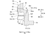
- FIG. 6 is a sectional view taken along line VII-VII in FIG.
- FIG. 6 is a sectional view taken along line VIII-VIII in FIG.
- the gas turbine 10 of the present embodiment has a compressor 20 that compresses air A and combustion that burns fuel F in the air A compressed by the compressor 20 to generate combustion gas G. It includes a vessel 30 and a turbine 40 driven by a combustion gas G.
- the compressor 20 has a compressor rotor 21 that rotates about the axis Ar, a compressor casing 25 that covers the compressor rotor 21, and a plurality of stationary blade rows 26.
- the turbine 40 has a turbine rotor 41 that rotates about the axis Ar, a turbine casing 45 that covers the turbine rotor 41, and a plurality of stationary blade rows 46.
- the direction in which the axis Ar extends is referred to as the axial direction Da
- the circumferential direction centered on the axis Ar is simply referred to as the circumferential direction Dc
- the direction perpendicular to the axis Ar is referred to as the radial direction Dr.
- one side of the axial direction Da is referred to as an axial upstream side Dau, and the opposite side is referred to as an axial downstream side Dad.
- the side approaching the axis Ar in the radial direction is the radial inner Dri, and the opposite side is the radial outer Dro.
- the compressor 20 is arranged on the Dau on the upstream side of the axis with respect to the turbine 40.
- the compressor rotor 21 and the turbine rotor 41 are located on the same axis Ar and are connected to each other to form the gas turbine rotor 11.
- the rotor of the generator GEN is connected to the gas turbine rotor 11.
- the gas turbine 10 further includes an intermediate casing 16. This intermediate casing is arranged between the compressor casing 25 and the turbine casing 45 in the axial direction Da.
- the compressor casing 25, the intermediate casing 16 and the turbine casing 45 are connected to each other to form the gas turbine casing 15.
- the compressor rotor 21 has a rotor shaft 22 extending in the axial direction Da about the axis Ar, and a plurality of rotor blade rows 23 attached to the rotor shaft 22.
- the plurality of blade rows 23 are arranged in the axial direction Da.
- Each of the moving blade rows 23 is composed of a plurality of moving blades 23a arranged in the circumferential direction Dc.
- a stationary blade row 26 of any one of the plurality of stationary blade rows 26 is arranged on the Dad on the downstream side of each axis of the plurality of moving blade rows 23.
- Each vane row 26 is provided inside the compressor casing 25.
- Each of the stationary blade rows 26 is composed of a plurality of stationary blades 26a arranged in the circumferential direction Dc.
- the turbine rotor 41 has a rotor shaft 42 extending in the axial direction Da about the axis Ar, and a plurality of blade rows 43 attached to the rotor shaft 42.
- the plurality of blade rows 43 are arranged in the axial direction Da.
- Each of the moving blade rows 43 is composed of a plurality of moving blades 43a arranged in the circumferential direction Dc.
- a stationary blade row 46 of any one of the plurality of stationary blade rows 46 is arranged on each axis upstream Dau of the plurality of moving blade rows 43.
- Each vane row 46 is provided inside the turbine casing 45.
- Each of the stationary blade rows 46 is composed of a plurality of stationary blades 46a arranged in the circumferential direction Dc.
- the turbine casing 45 includes a tubular outer casing 45a constituting the outer shell, an inner casing 45b fixed to the inside of the outer casing 45a, and a plurality of dividing rings 45c fixed to the inside of the inner casing 45b.
- the plurality of dividing rings 45c are all provided at positions between the plurality of stationary blade rows 46. Therefore, the rotor blade row 43 is arranged on the radial inner Dri of each dividing ring 45c.
- the annular space between the outer peripheral side of the rotor shaft 42 and the inner peripheral side of the turbine casing 45 where the stationary blades 46a and the moving blades 43a are arranged in the axial direction Da is the combustion gas G from the combustor 30.
- the inner casing 45b of the turbine casing 45 is formed with a cooling air passage 45p penetrating from the radial outer Dro to the radial inner Dri.
- the cooling air that has passed through the cooling air passage 45p is introduced into the stationary blade 46a and the split ring 45c and used for cooling the stationary blade 46a and the split ring 45c.
- the air in the gas turbine casing 15 is supplied as cooling air to the stationary blades 46a constituting the stationary blade row 46 without passing through the cooling air passage 45p of the turbine casing 45. There is also.
- the combustor 30 is attached to the intermediate casing 16.
- the combustor 30 includes an inner cylinder (or combustion cylinder) 33 on which fuel burns, a plurality of burners 31 that inject fuel into the inner cylinder 33, and a burner that supports the plurality of burners 31. It has a frame 32 and a tail cylinder 35 connected to the downstream side of the inner cylinder 33.
- the tail cylinder 35 has a tubular cylinder 36 around the combustor axis Ca, and a flange 37 protruding from one end of the cylinder 36 to the outer peripheral side.
- a burner frame 32 is attached to the other end of the cylinder 36.
- the inner peripheral side of the cylinder 36 forms a combustion space.
- the cylinder 36 extends to the cad on the downstream side of the axis when the combustor 30 is attached to the intermediate casing 16.
- the flange 37 is provided at the downstream end of the cad on the downstream side of the axis of the cylinder 36.
- the stationary blades 46a constituting the first-stage stationary blade row 46 on the most upstream side of the axis Dau and the flange 37 of the tail cylinder 35 are connected by an outlet seal 90.
- the compressor 20 compresses air A to generate compressed air.
- This compressed air flows into the combustor 30.
- Fuel F is supplied to the combustor 30.
- the fuel F is burned in the compressed air to generate a high-temperature and high-pressure combustion gas G.
- This combustion gas G is sent from the combustor 30 to the combustion gas flow path 49 in the turbine 40.
- the combustion gas G rotates the turbine rotor 41 in the process of flowing through the combustion gas flow path 49 to DadDad on the downstream side of the axis.
- the rotation of the turbine rotor 41 rotates the rotor of the generator GEN connected to the gas turbine rotor 11.
- the generator GEN generates electricity.
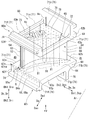
- the stationary blade 50 of the present embodiment has a blade body 51, an inner shroud 60i provided on one side of the blade body 51 in the blade height direction Dh, and a blade height of the blade body 51. It has an outer shroud 60o provided on the other side in the direction Dh.
- the blade height direction Dh becomes the radial direction Dr.
- the height direction first side Dh1 which is one side of the blade height direction Dh becomes the radial outer side Dr
- the height direction second side Dh2 which is the other side of the blade height direction Dh becomes the radial inner side.
- the inner shroud 60i is provided on the radial inner Dri of the blade body 51
- the outer shroud 60o is provided on the radial outer Dro of the blade body 51.
- the blade height direction Dh will be referred to as the radial direction Dr
- the height direction first side Dh1 will be referred to as the radial outer Dro
- the height direction second side Dh2 will be referred to as the radial inner Dri.
- the wing body 51 has a front edge 52, a trailing edge 53, a negative pressure surface (back side surface) 54 which is a convex surface, and a positive pressure surface which is a concave surface. It has (ventral surface) 55 and.
- the front edge 52 and the trailing edge 53 exist at the connecting portion between the negative pressure surface 54 and the positive pressure surface 55.
- the front edge 52, the trailing edge 53, the negative pressure surface 54, and the positive pressure surface 55 all extend in the radial direction Dr, which is the blade height direction Dh.
- the front edge 52 is located on the Dau on the upstream side of the axis with respect to the trailing edge 53 in a state where the stationary blade 50 is attached to the turbine casing 45.
- the blade body 51 is arranged in the combustion gas flow path 49 through which the combustion gas G passes.
- the inner shroud 60i defines the edge of the radial inner Dri of the annular combustion gas flow path 49.
- the outer shroud 60o defines the edge of the radial outer Dro of the annular combustion gas flow path 49.
- the inner shroud 60i has a shroud main body 61, a peripheral wall 71, an upstream protrusion 74, and a retainer 76.
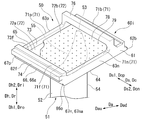
- the shroud main body 61 is a plate-shaped member that spreads in a direction including a directional component in a direction perpendicular to the radial direction Dr, which is the blade height direction Dh.
- the shroud main body 61 has a gas path surface 64, an anti-gas path surface 65, a front end surface 62f, a rear end surface 62b, a negative pressure side end surface 63n, and a positive pressure side end surface 63p.
- the gas path surface 64 is a surface that faces the outer Dro in the radial direction, which is the first side Dh1 in the height direction, and is in contact with the combustion gas G.
- the anti-gas path surface 65 is a surface facing the inner Dri in the radial direction, which is the second side Dh2 in the height direction.
- the anti-gas path surface 65 has a back-to-back relationship with the gas path surface 64.
- the front end surface 62f is located on the Dau on the upstream side of the axis line with respect to the blade body 51, and is a surface facing the Dau on the upstream side of the axis line.
- the rear end surface 62b is located on the Dad on the downstream side of the axis of the blade 51 and faces the Dad on the downstream side of the axis.
- the negative pressure side end surface 63n is a side end surface on the negative pressure side where the negative pressure surface 54 of the blade body 51 exists with reference to the camber line CL of the blade body 51, and is a surface located on the negative pressure side of the blade body 51.
- the negative pressure side end surface 63n connects the front end surface 62f and the rear end surface 62b.
- the positive pressure side end surface 63p is a side end surface on the positive pressure side where the positive pressure surface 55 of the blade body 51 exists with reference to the camber line CL of the blade body 51, and is a surface located on the positive pressure side of the blade body 51.
- the positive pressure side end surface 63p connects the front end surface 62f and the rear end surface 62b.
- the positive pressure side end surface 63p is located on the opposite side of the negative pressure side end surface 63n with reference to the blade body 51.
- the rear end surface 62b is substantially parallel to the front end surface 62f.
- the positive pressure side end surface 63p is substantially parallel to the negative pressure side end surface 63n. Therefore, the shroud main body 61 has a parallel quadrilateral shape as shown in FIG. 6 when viewed from the radial direction Dr.
- the direction in which the positive pressure side end surface 63p and the negative pressure side end surface 63n are aligned and orthogonal to the axis Ar is defined as the lateral direction Ds.
- the lateral Ds becomes the circumferential Dc.
- the lateral first side Ds1 which is one side of the lateral Ds becomes the circumferential positive pressure side Dcp
- the lateral second side Ds2 which is the other side of the lateral Ds becomes the circumferential negative pressure side Dcn. Therefore, in the following, the lateral direction Ds will be referred to as the circumferential direction Dc.
- the first side Ds1 in the lateral direction is defined as the positive pressure side Dcp in the circumferential direction
- the second Ds2 in the lateral direction is defined as the negative pressure side Dcn in the circumferential direction.
- the shroud body 61 further has a front end corner portion 66, a front end positive pressure side corner portion 67p, and a front end negative pressure side corner portion 67n.
- the front end surface 66 is a corner between the gas path surface 64 and the front end surface 62f.
- the front end angle portion 66 includes a front end inclined surface 66a that is inclined with respect to each of the front end surface 62f and the positive pressure side end surface 63p.
- the front end positive pressure side corner portion 67p is a corner portion of the gas path surface 64, the front end surface 62f, and the positive pressure side end surface 63p.
- the front end negative pressure side corner portion 67n is a corner portion of the gas path surface 64, the front end surface 62f, and the negative pressure side end surface 63n.
- the front end negative pressure side corner portion 67n includes a front end negative pressure side inclined surface 67na that is inclined with respect to each of the gas path surface 64, the front end surface 62f, and the negative pressure side end surface 63n.
- the front end inclined surface 66a is drawn as a curved surface that is inclined with respect to each of the front end surface 62f and the positive pressure side end surface 63p and connects the front end surface 62f and the positive pressure side end surface 63p. ..
- the front end inclined surface 66a may be a plane connecting the front end surface 62f and the positive pressure side end surface 63p as long as it is inclined with respect to each of the front end surface 62f and the positive pressure side end surface 63p.
- the peripheral wall 71 is a wall that projects from the shroud main body 61 to the inner Dri in the radial direction along the outer peripheral edge of the shroud main body 61.
- the peripheral wall 71 has a front peripheral wall 71f and a rear peripheral wall 71b facing each other in the axial direction Da, and a positive pressure side peripheral wall 71p and a negative pressure side peripheral wall 71n facing each other in the circumferential direction Dc.
- the front peripheral wall 71f is located on the Dau on the upstream side of the axis of the blade body 51.
- the front peripheral wall 71f projects from the shroud main body 61 to the radial outer Dro and the radial inner Dri from the positive pressure side peripheral wall 71p and the negative pressure side peripheral wall 71n.
- the surface of the front peripheral wall 71f facing the upstream side of the axis forms a part of the front end surface 62f of the inner shroud 60i.
- the rear peripheral wall 71b is located on the Dad on the downstream side of the axis of the blade body 51.
- the positive pressure side peripheral wall 71p is located on the positive pressure side Dcp in the circumferential direction with respect to the blade body 51.
- the surface of the positive pressure side peripheral wall 71p facing the positive pressure side Dcp in the circumferential direction forms a part of the positive pressure side end surface 63p of the inner shroud 60i.
- the negative pressure side peripheral wall 71n is located on the negative pressure side Dcn in the circumferential direction with respect to the blade body 51.
- the surface of the negative pressure side peripheral wall 71n facing the negative pressure side Dcn in the circumferential direction forms a part of the negative pressure side end surface 63n of the inner shroud 60i.
- a cavity 72 recessed toward the inner Dri in the radial direction is formed by the shroud main body 61 and the peripheral wall 71.
- the cavity 72 has an anti-gas path surface 65 of the shroud main body 61, a surface of the front peripheral wall 71f facing the axial downstream side Dad, a surface of the rear peripheral wall 71b facing the axial upstream side Dau, and a positive pressure side peripheral wall 71p in the circumferential negative pressure side. It is defined by a surface facing Dcn and a surface of the peripheral wall 71n on the negative pressure side facing the positive pressure side Dcp in the circumferential direction. Therefore, these surfaces form a cavity defining surface 73 that defines the cavity 72.
- the surface of the front peripheral wall 71f facing the downstream side of the axis Dad is referred to as the cavity front demarcating surface 73f.
- the retainer 76 is located between the front peripheral wall 71f and the rear peripheral wall 71b in the axial direction Da, and is formed from the negative pressure side end surface 63n to the positive pressure side end surface 63p.
- the retainer 76 is connected to the end 17a (see FIGS. 2 and 3) of the radial outer Dro of the inner cover 17 fixed to the gas turbine casing 15, and the portion of the radial inner Dri of the stationary blade 50 is inside. It plays a role of supporting the cover 17.
- the upstream side projecting portion 74 projects from a position away from the gas path surface 64 in the front end surface 62f to the axial upstream side Dau.
- the stationary blade 50 further includes a collision plate 78.
- the collision plate 78 divides the cavity 72 into a first-side cavity 72a, which is a region of the radial outer Dro, and a second-side cavity 72b, which is a region of the radial inner Dri.
- a plurality of through holes 79 penetrating in the radial direction Dr are formed in the collision plate 78.
- a part of the cooling air Ac existing in the radial inner Dri of the vane 50 flows into the second side cavity 72b.
- a part of the cooling air that has flowed into the second side cavity 72b flows into the first side cavity 72a through the through hole 79 of the collision plate 78, and impinge-cools the anti-gas path surface 65.
- the outer shroud 60o is basically the same as the configuration of the inner shroud 60i. Therefore, the outer shroud 60o also has the shroud main body 61, the peripheral wall 71, and the upstream side protrusion 74, similarly to the inner shroud 60i. However, the outer shroud 60o does not have a portion corresponding to the retainer 76 of the inner shroud 60i. Similar to the shroud main body 61 of the inner shroud 60i, the shroud main body 61 of the outer shroud 60o also has a gas path surface 64, an anti-gas path surface 65, a front end surface 62f, a rear end surface 62b, a negative pressure side end surface 63n, and a positive pressure side end surface.
- the peripheral wall 71 of the outer shroud 60o also has a front peripheral wall 71f, a rear peripheral wall 71b, a positive pressure side peripheral wall 71p, and a negative pressure side peripheral wall 71n, similarly to the peripheral wall 71 of the inner shroud 60i.
- the front peripheral wall 71f and the rear peripheral wall 71b of the outer shroud 60o serve to attach the stationary blade 50 to the inner peripheral side of the turbine casing 45 (see FIG. 2).
- the above-mentioned outlet seal 90 is formed in the outer outlet seal 90o connecting the radial outer Dro portion and the outer shroud 60o in the flange 37 of the tail cylinder 35 and in the flange 37 of the tail cylinder 35. It has an inner outlet seal 90i that connects the portion of the radial inner Dri and the inner shroud 60i.
- the inner outlet seal 90i includes a main plate 91, a downstream first plate 92a, a downstream second plate 92b, an upstream first plate 93a, and an upstream second plate 93b.
- the main plate 91 extends in the circumferential direction Dc and the radial direction Dr.
- the downstream first plate 92a and the downstream second plate 92b extend in the circumferential direction Dc and the axial direction Da.
- the downstream first plate 92a extends from the end of the radial outer Dro of the main plate 91 to the axis downstream Dad.
- the downstream second plate 92b extends from a position substantially intermediate between the end of the radial outer Dro and the end of the radial inner Dri of the main plate 91 to the cad on the downstream side of the axis.
- the downstream side second plate 92b faces the downstream side first plate 92a in the radial direction Dr at intervals in the radial direction Dr.
- the upstream first plate 93a extends in the circumferential direction Dc and the axial direction Da.
- the upstream side first plate 93a extends from the end of the radial inner Dri of the main plate 91 to the axis upstream side Dau.
- the upstream second plate 93b extends in the circumferential direction Dc and the radial direction Dr.
- the upstream second plate 93b extends from the end of the axial upstream Dau of the upstream first plate 93a to the outer Dro in the radial direction.
- the upstream second plate 93b faces the main plate 91 in the axial direction Da at intervals in the axial direction Da.
- the member closest to the combustion gas flow path 49 in the radial direction is the downstream first plate 92a.
- the downstream first plate 92a is located at the inner Dri in the radial direction with respect to the cylinder 36 of the tail cylinder 35 and the shroud main body 61 of the inner shroud 60i. Therefore, the downstream first plate 92a is separated from the combustion gas flow path 49 in the radial direction Dr.
- the inner outlet seal 90i has a tail cylinder connecting portion 94, a stationary blade connecting portion 95, and a cooling air passage 96.
- the tail cylinder connecting portion 94 is a groove recessed toward the inner Dri in the radial direction so that the flange 37 of the tail cylinder 35 can be inserted.
- the tail cylinder connecting portion 94 which is a groove, is formed by a main plate 91, an upstream first plate 93a, and an upstream second plate 93b.
- the stationary blade connecting portion 95 is a groove recessed toward the upstream Dau of the axis so that the upstream protruding portion 74 of the inner shroud 60i can enter.
- the stationary blade connecting portion 95 which is a groove, is formed by a main plate 91, a downstream first plate 92a, and a downstream second plate 92b.
- the cooling air passage 96 has an inlet 96i that opens at the end of the radial inner Dri of the main plate 91, and an outlet 96o that opens at the end of the axis downstream Dad of the downstream first plate 92a.
- the flange 37 of the tail tube 35 and the portion of the front end surface 62f of the inner shroud 60i that is separated from the gas path surface 64 are opposed to each other at intervals in the axial direction Da.
- the gap in the axial direction Da between the rear end surface 36b of the cylinder 36 and the front end surface 66 and the front end surface 62f of the inner shroud 60i forms the first gap S1.
- the space surrounded by the flange 37 of the tail tube 35, the front end surface 62f of the inner shroud 60i, and the downstream first plate 92a of the inner exit seal 90i forms a second gap S2. Therefore, the second gap S2 exists at a position separated from the combustion gas flow path 49 in the radial direction Dr.
- the first gap S1 and the second gap S2 are connected to each other in the radial direction Dr to form one gap space S.
- the outlet seal 90 also plays a role of preventing a part of the combustion gas G flowing in the tail cylinder 35 from flowing out into the intermediate casing 16 through the gap space S.
- the outer outlet seal 90o has the same configuration as the inner outlet seal 90i. However, the mutual relationship of the radial Dr in the component of the outer outlet seal 90o is opposite to the mutual relationship of the radial Dr in the component of the inner outlet seal 90i. Therefore, for example, the downstream first plate 92a of the outer outlet seal 90o is provided at the end of the radial inner Dri in the main plate 91 of the outer outlet seal 90o. Further, the tail cylinder connecting portion 94 of the outer outlet seal 90o is a groove recessed toward the outer Dro in the radial direction.
- a plurality of blade air passages 81 extending in the radial direction Dr are formed in the blade body 51, the outer shroud 60o, and the inner shroud 60i.
- Each wing air passage 81 is formed so as to be continuous from the outer shroud 60o to the inner shroud 60i via the wing body 51.
- the plurality of blade air passages 81 are lined up along the camber line CL of the blade body 51.
- a part of the adjacent wing air passage 81 communicates with each other at a portion of the radial outer Dro or a portion of the radial inner Dri.
- one of the plurality of wing air passages 81 is opened by the anti-gas path surface 65 of the outer shroud 60o.
- one of the plurality of wing air passages 81 is opened by the anti-gas path surface 65 of the inner shroud 60i.
- a part of the cooling air Ac existing in the radial outer Dro or the radial inner Dri of the vane 50 flows into the blade air passage 81 through the opening of the blade air passage 81.
- a plurality of blade surface ejection passages 82 penetrating from the blade air passage 81 to the combustion gas flow path 49 are formed in the front edge 52 and the trailing edge 53 of the blade body 51.
- a plurality of rear end passages 83, a plurality of first air passages 84, a plurality of second air passages 85, and a third air passage 86 are provided in the inner shroud 60i, as shown in FIGS. 5 and 6, a plurality of rear end passages 83, a plurality of first air passages 84, a plurality of second air passages 85, and a third air passage 86 are provided. It is formed.
- the plurality of rear end passages 83 are lined up in the circumferential direction Dc. These rear end passages 83 have an inlet 83i and an outlet 83o.
- the inlet 83i is a surface that defines the first-side cavity 72a, and is formed on a surface of the rear peripheral wall 71b that faces the upstream side of the axis Dau.
- the outlet 83o is formed on the rear end surface 62b.
- the plurality of first air passages 84 are arranged in the circumferential direction Dc. As shown in FIG. 7, these first air passages 84 have a first inlet 84i and a first outlet 84o.
- the first inlet 84i is opened at a portion defining the second cavity 72b in the cavity front defining surface 73f.
- the first outlet 84o is opened at the front end inclined surface 66a in the front end corner portion 66.
- the first air passage 84 has a first outlet side portion 84po including the first outlet 84o in the first air passage 84.
- the first exit side portion 84po is formed so as to gradually move toward the outer Dro in the radial direction toward the upstream side Dau of the axis. Further, the first outlet side portion 84po is gradually inclined toward the circumferential positive pressure side Dcp toward the upstream side Dau of the axis line (see FIG. 6).
- the plurality of second air passages 85 are arranged in the circumferential direction Dc.
- the plurality of first air passages 84 and the plurality of second air passages 85 are alternately arranged in the circumferential direction Dc.
- these second air passages 85 have a second inlet 85i and a second outlet 85o.
- the second inlet 85i is opened at a portion defining the second cavity 72b in the cavity front defining surface 73f.
- the second outlet 85o is open at the front end surface 62f.
- the second outlet 85o faces the rear end surface 36b of the cylinder 36 in the axial direction Da.
- the second air passage 85 has a second outlet side portion 85po including the second outlet 85o in the second air passage 85.
- the second exit side portion 85po is formed so as to gradually move toward the outer Dro in the radial direction toward the upstream side Dau of the axis.
- the third air passage 86 has a third inlet 86i and a third outlet 86o.
- the third inlet 86i is opened at a portion defining the second cavity 72b in the cavity front defining surface 73f.
- the third outlet 86o is opened at the front end negative pressure side inclined surface 67na in the front end negative pressure side corner portion 67n.
- the third air passage 86 has a third outlet side portion 86po including the third outlet 86o in the third air passage 86.
- the third exit side portion 86po is formed so as to gradually move toward the outer Dro in the radial direction toward the upstream side Dau of the axis. Further, the third outlet side portion 86po is gradually inclined toward the circumferential negative pressure side Dcn toward the upstream side Dau of the axis line.
- a plurality of rear end passages 83 and a plurality of fourth air passages 87 are formed in the outer shroud 60o.
- the plurality of rear end passages 83 are arranged in the circumferential direction Dc like the plurality of rear end passages 83 of the inner shroud 60i. These rear end passages 83 have an inlet 83i and an outlet 83o.
- the inlet 83i is a surface defining the first side cavity 72a of the outer shroud 60o, and is formed on a surface of the rear peripheral wall 71b facing the upstream side Dau of the axis.
- the outlet 83o is formed on the rear end surface 62b of the outer shroud 60o.
- the plurality of fourth air passages 87 are lined up in the circumferential direction Dc. These fourth air passages 87 have a fourth inlet 87i and a fourth outlet 87o.
- the fourth entrance 87i is opened at a portion defining the first cavity 72a in the cavity front defining surface 73f of the outer shroud 60o.
- the fourth exit 87o is opened at the front end surface 62f of the outer shroud 60o.
- the outer shroud 60o may be formed with a first air passage 84 and a second air passage 85 instead of the above fourth air passage 87. Further, a third air passage 86 may be formed in the outer shroud 60o. In this way, when the first air passage 84, the second air passage 85, etc. are formed in the outer shroud 60o, the height direction first side Dh1 for the outer shroud 60o becomes the radial inner Dri, and the outer shroud The second side Dh2 in the height direction for 60o is the outer Dro in the radial direction. Therefore, for example, the first outlet side portion 84po in the first air passage 84 formed in the outer shroud 60o is formed so as to gradually move toward the inner Dri in the radial direction toward the upstream side Dau of the axis.
- the stationary blade 50 is exposed to the high temperature combustion gas G while the gas turbine 10 is being driven. Therefore, various passages are formed in the stationary blade 50, and air is passed through the passages to cool the stationary blade 50.
- a pressure distribution is generated in the circumferential direction Dc around the upstream side of the stationary blade 50 due to the relationship of the combustion gas flow flowing between the two stationary blades 50 adjacent to each other in the circumferential direction Dc. That is, around the upstream side of the stationary blade 50, the pressure of the portion on the first side Ds1 (positive pressure side) in the lateral direction becomes higher with reference to the front edge 52 of the blade body 51, and the pressure on the second side Ds2 in the lateral direction is relatively high. The pressure on the (negative pressure side) becomes low.
- the combustion gas flowing through the combustion gas flow path 49 is laterally oriented with respect to the front edge 52 of the blade body 51 between the rear end surface 36b of the tail cylinder 35 and the front end surface 62f of the inner shroud 60i.
- the combustion gas G is more likely to flow into the gap space S from the portion of the first side Ds1 (positive pressure side) in the lateral direction than the portion of the second side Ds2 (negative pressure side). Further, a part of the inflowing combustion gas G moves in the gap space S in the circumferential direction Dc and is discharged to the combustion gas flow path 49 on the second side Ds2 in the low pressure side.
- the gas path surface 64 of the inner shroud 60i is exposed to the combustion gas G. Further, when no air is flowing through the first air passage 84 and the second air passage 85, the combustion gas G flows into the gap space S between the tail tube 35 and the inner shroud 60i as described above. Therefore, the front end corner portion 66, which is a corner portion between the gas path surface 64 and the front end surface 62f, is heated on two sides by heat input from the gas path surface 64 side and the front end surface 62f side. Therefore, the front end corner portion 66 is more easily heated by the combustion gas G than the gas path surface 64 and the front end surface 62f.
- Compressed air in the intermediate casing 16 flows into the second side cavity 72b of the inner shroud 60i.
- a part of this compressed air flows into the first air passage 84 from the first inlet 84i as cooling air Ac.
- the other part of this compressed air flows into the second air passage 85 from the second inlet 85i as cooling air Ac.
- the other part of the compressed air flows into the third air passage 86 (see FIG. 8) from the third inlet 86i as the cooling air Ac.
- the cooling air Ac flowing into the first air passage 84 convection-cools the portion of the inner shroud 60i on the upstream side of the axis, especially the portion of the gas path surface 64 on the upstream side of the axis. To do.
- the cooling air Ac flows out into the combustion gas flow path 49 from the first outlet 84o formed at the front end corner portion 66.
- the cooling air Ac flowing out into the combustion gas flow path 49 functions as purge air, suppresses the combustion gas G from reaching the front end corner 66, and suppresses the heating of the front end corner 66 by the combustion gas G.
- the cooling air Ac flowing out into the combustion gas flow path 49 functions as purge air for suppressing the combustion gas G from flowing into the gap space S between the tail tube 35 and the inner shroud 60i, and also functions as the combustion gas G. By diluting the gas, the temperature of the gas flowing into the gap space S is lowered.
- the first outlet side portion 84po of the first air passage 84 gradually heads toward the outer Dro in the radial direction toward the upstream side Dau of the axis line. Therefore, the cooling air Ac flowing out from the first air passage 84 gradually goes toward the outer Dro in the radial direction as it goes toward the Dau on the upstream side of the axis. Therefore, the cooling air Ac flowing out from the first air passage 84 can effectively suppress the combustion gas G from reaching the front end corner portion 66, and can also suppress the combustion gas G from flowing into the gap space S. Further, the first outlet side portion 84po gradually approaches the circumferential positive pressure side Dcp toward the upstream side Dau of the axis line.
- the first air passage 84 is radially Dr.
- the passage length of the first air passage 84 can be lengthened by forming it as an inclined passage that also extends. Therefore, the cooling air Ac passing through the first air passage 84 can effectively convection-cool the portion of the inner shroud 60i on the upstream side of the axis.
- the cooling air Ac passing through the first air passage 84 has the effect of convection cooling the inner shroud 60i exposed to the combustion gas G. Further, the cooling air Ac flowing out from the first air passage 84 has an effect as purge air that suppresses the contact of the combustion gas G with the inner shroud 60i and suppresses the heating of the inner shroud 60i.
- the first air passage 84 has a greater effect of convection cooling by the cooling air Ac passing through the first air passage 84 than the effect of allowing the cooling air Ac flowing out of the first air passage 84 to function as purge air. It is a passage.
- the cooling air Ac that has flowed into the second air passage 85 convection-cools the portion of the inner shroud 60i on the upstream side of the axis, particularly around the front end surface 62f, in the process of passing through the second air passage 85.
- the cooling air Ac flows out into the gap space S from the second outlet 85o formed on the front end surface 62f.
- the cooling air Ac flowing out into the gap space S suppresses the combustion gas G from reaching the front end surface 62f facing the gap space S, so that the front end surface 62f and the rear end surface 36b of the tail tube 35 due to the combustion gas G Suppress the heating of.
- the cooling air Ac cools the area around the front end surface 62f by convection and dilutes the combustion gas G flowing into the gap space S to lower the gas temperature in the gap space S, thereby lowering the front end surface 62f and the tail tube 35. It suppresses heating of the rear end surface 36b and its surroundings. Further, the cooling air Ac flowing out into the gap space S functions as purge air that suppresses the combustion gas G from flowing into the gap space S.
- the second outlet side portion 85po of the second air passage 85 gradually heads toward the outer Dro in the radial direction toward the upstream side Dau of the axis line. Therefore, the cooling air Ac flowing out from the second air passage 85 gradually goes toward the outer Dro in the radial direction as it goes toward the Dau on the upstream side of the axis. Therefore, the cooling air Ac flowing out from the second air passage 85 can effectively suppress the combustion gas G from flowing into the gap space S.
- the second air passage 85 is a passage in which the effect of making the cooling air Ac function as purge air is greater than the effect of convection cooling as compared with the first air passage 84.
- the cooling air Ac flowing into the third air passage 86 is a portion of the inner shroud 60i on the upstream side of the axis, particularly the Dau on the upstream side of the axis of the gas path surface 64 and in the circumferential direction.
- the portion of the negative pressure side Dcn and the portion of the negative pressure side end surface 63n on the upstream side of the axis line Dau are convected-cooled.
- the cooling air Ac flows out into the combustion gas flow path 49 from the third outlet 86o formed at the front end negative pressure side corner portion 67n.
- the cooling air Ac flowing out into the combustion gas flow path 49 suppresses the combustion gas G from reaching the front end negative pressure side corner 67n, thereby suppressing the heating of the front end negative pressure side corner 67n by the combustion gas G. That is, the cooling air Ac cools the front end negative pressure side corner portion 67n and its surroundings with a film. Further, the cooling air Ac flowing out into the combustion gas flow path 49 suppresses the combustion gas G from flowing into the gap space S between the tail tube 35 and the inner shroud 60i, and the gas flowing into the gap space S. Lower the temperature of.
- the first air passage 84 and the second air passage 85 only one of the air passages can cool the portion of the inner shroud 60i on the upstream side of the axis, and can suppress thermal damage in this portion.
- a case where the portion of the inner shroud 60i on the upstream side of the axis Dau is cooled only by the first air passage 84 will be considered.
- the effect of the second air passage 85 also needs to be borne by the first air passage 84. Therefore, for example, by increasing the passage cross-sectional area of the first air passage 84, the flow rate of the cooling air Ac flowing through the first air passage 84 flows through the first air passage 84 and the second air passage 85 in the present embodiment. It needs to be larger than the total flow rate of the cooling air Ac.
- the portion of the inner shroud 60i on the upstream side of the axis Dau is cooled only by the second air passage 85.
- the effect of the first air passage 84 also needs to be borne by the first air passage 84. Therefore, for example, by increasing the number of the second air passages 85, the flow rate of the cooling air Ac flowing through the second air passage 85 is adjusted to the cooling air flowing through the first air passage 84 and the second air passage 85 in the present embodiment. It needs to be larger than the total flow rate of Ac.
- the inner shroud 60i of the present embodiment has the first air passage 84 and the second air passage 85, the inner shroud 60i is effectively cooled to improve the durability of the inner shroud 60i.
- the amount of cooling air Ac used to cool the inner shroud 60i can be suppressed.
- the number of the first air passages 84 and the number of the second air passages 85 do not have to be the same.
- the number of the first air passages 84 may be larger than the number of the second air passages 85.
- the number of the second air passages 85 may be larger than the number of the first air passages 84. Therefore, it is not necessary to arrange the plurality of first air passages 84 and the plurality of second air passages 85 alternately in the circumferential direction Dc.
- the total passage cross-sectional area of the first air passage 84 and the total passage cross-sectional area of the second air passage 85 do not have to be the same.
- the passage cross-sectional area of the first air passage 84 may be larger than the passage cross-sectional area of the second air passage 85.
- first outlet 84o of the first air passage 84 it is not necessary to arrange the first outlet 84o of the first air passage 84 in the entire front end corner portion 66 of the inner shroud 60i except for the end of the circumferential positive pressure side Dcp and the end of the circumferential negative pressure side Dcn. Further, it is not necessary to arrange the second outlet 85o of the second air passage 85 in the entire front end surface 62f of the inner shroud 60i except for the end of the circumferential positive pressure side Dcp and the end of the circumferential negative pressure side Dcn.
- the combustion gas G is located between the rear end surface 36b of the tail tube 35 and the front end surface 62f of the inner shroud 60i from the portion of the circumferential negative pressure side Dcn with reference to the front edge 52 of the blade body 51.
- the combustion gas G easily flows into the gap space S from the portion of the Dcp on the positive pressure side in the circumferential direction. Therefore, for example, the first outlet 84o of the first air passage 84 may be arranged only on the positive pressure side Dcp in the circumferential direction with reference to the front edge 52 of the blade body 51 in the front end corner portion 66.
- the second outlet 85o of the second air passage 85 may be arranged only on the circumferential positive pressure side Dcp with reference to the front edge 52 of the blade body 51.
- the first outlet 84o of the first air passage 84 is arranged only on the circumferential positive pressure side Dcp with reference to the front edge 52 of the blade body 51, and the front end surface 62f.
- the second outlet 85o of the second air passage 85 does not have to be arranged in the entire area except the end of the circumferential positive pressure side Dcp and the end of the circumferential negative pressure side Dcn.
- the first outlet 84o of the first air passage 84 is arranged in the entire front end corner portion 66 except for the end of the circumferential positive pressure side Dcp and the end of the circumferential negative pressure side Dcn, and the wing of the front end surface 62f
- the second outlet 85o of the second air passage 85 may be arranged only on the circumferential positive pressure side Dcp with reference to the front edge 52 of the body 51.
- the outer shroud 60o may be formed with a first air passage 84 and a second air passage 85 instead of the fourth air passage 87. Further, a third air passage 86 may be formed in the outer shroud 60o.
- the stationary blade can be effectively cooled, and the amount of cooling air used can be suppressed while improving the durability.
Landscapes
- Engineering & Computer Science (AREA)
- General Engineering & Computer Science (AREA)
- Mechanical Engineering (AREA)
- Chemical & Material Sciences (AREA)
- Combustion & Propulsion (AREA)
- Physics & Mathematics (AREA)
- Fluid Mechanics (AREA)
- Turbine Rotor Nozzle Sealing (AREA)
- Sealing Using Fluids, Sealing Without Contact, And Removal Of Oil (AREA)
Priority Applications (2)
| Application Number | Priority Date | Filing Date | Title |
|---|---|---|---|
| KR1020217042181A KR102697750B1 (ko) | 2019-08-16 | 2020-08-06 | 정익, 및 이것을 포함하는 가스 터빈 |
| US17/623,021 US11834994B2 (en) | 2019-08-16 | 2020-08-06 | Turbine vane and gas turbine comprising same |
Applications Claiming Priority (2)
| Application Number | Priority Date | Filing Date | Title |
|---|---|---|---|
| JP2019-149245 | 2019-08-16 | ||
| JP2019149245A JP7451108B2 (ja) | 2019-08-16 | 2019-08-16 | 静翼、及びこれを備えているガスタービン |
Publications (1)
| Publication Number | Publication Date |
|---|---|
| WO2021033564A1 true WO2021033564A1 (ja) | 2021-02-25 |
Family
ID=74660913
Family Applications (1)
| Application Number | Title | Priority Date | Filing Date |
|---|---|---|---|
| PCT/JP2020/030187 Ceased WO2021033564A1 (ja) | 2019-08-16 | 2020-08-06 | 静翼、及びこれを備えているガスタービン |
Country Status (4)
| Country | Link |
|---|---|
| US (1) | US11834994B2 (enExample) |
| JP (1) | JP7451108B2 (enExample) |
| KR (1) | KR102697750B1 (enExample) |
| WO (1) | WO2021033564A1 (enExample) |
Families Citing this family (5)
| Publication number | Priority date | Publication date | Assignee | Title |
|---|---|---|---|---|
| FR3114838B1 (fr) * | 2020-10-01 | 2023-06-16 | Safran Aircraft Engines | Aube de turbine pour turbomachine d’aéronef, comprenant une plateforme pourvue d’un canal de réjection de flux primaire vers une cavité de purge |
| US11643969B2 (en) * | 2021-04-16 | 2023-05-09 | General Electric Company | Split casings and methods of forming and cooling casings |
| JP7591977B2 (ja) * | 2021-05-31 | 2024-11-29 | 三菱重工業株式会社 | 静翼セグメント、ガスタービン、及び静翼セグメントの製造方法 |
| JP7646037B2 (ja) | 2022-01-06 | 2025-03-14 | 三菱重工業株式会社 | タービン静翼及び嵌合構造並びにガスタービン、並びに嵌合構造の冷却空気量を調整する方法 |
| FR3133063B1 (fr) * | 2022-02-25 | 2024-08-02 | Safran Aircraft Engines | Aubage de turbomachine, comprenant une pale et une plateforme qui présente un canal interne d’aspiration et d’éjection de flux |
Citations (7)
| Publication number | Priority date | Publication date | Assignee | Title |
|---|---|---|---|---|
| JPH11200807A (ja) * | 1998-01-12 | 1999-07-27 | Hitachi Ltd | 冷媒回収型ガスタービンおよびその静翼 |
| US6082961A (en) * | 1997-09-15 | 2000-07-04 | Abb Alstom Power (Switzerland) Ltd. | Platform cooling for gas turbines |
| DE102005024696A1 (de) * | 2004-06-15 | 2006-01-05 | Alstom Technology Ltd | Bauteil mit verbesserter Kühlfluidzuführung |
| JP2006105076A (ja) * | 2004-10-08 | 2006-04-20 | Mitsubishi Heavy Ind Ltd | ガスタービン |
| JP2007154902A (ja) * | 2005-12-08 | 2007-06-21 | General Electric Co <Ge> | タービンエンジンノズルアセンブリ及びガスタービンエンジン |
| JP2016070082A (ja) * | 2014-09-26 | 2016-05-09 | 三菱日立パワーシステムズ株式会社 | シール部材 |
| JP2020029852A (ja) * | 2018-08-24 | 2020-02-27 | 三菱日立パワーシステムズ株式会社 | 翼およびガスタービン |
Family Cites Families (6)
| Publication number | Priority date | Publication date | Assignee | Title |
|---|---|---|---|---|
| US6887033B1 (en) * | 2003-11-10 | 2005-05-03 | General Electric Company | Cooling system for nozzle segment platform edges |
| US8118554B1 (en) * | 2009-06-22 | 2012-02-21 | Florida Turbine Technologies, Inc. | Turbine vane with endwall cooling |
| JP2012107628A (ja) | 2012-01-27 | 2012-06-07 | Mitsubishi Heavy Ind Ltd | ガスタービン |
| JP5506834B2 (ja) | 2012-01-27 | 2014-05-28 | 三菱重工業株式会社 | ガスタービン |
| JP6263365B2 (ja) | 2013-11-06 | 2018-01-17 | 三菱日立パワーシステムズ株式会社 | ガスタービン翼 |
| JP5676040B1 (ja) * | 2014-06-30 | 2015-02-25 | 三菱日立パワーシステムズ株式会社 | 静翼、これを備えているガスタービン、静翼の製造方法、及び静翼の改造方法 |
-
2019
- 2019-08-16 JP JP2019149245A patent/JP7451108B2/ja active Active
-
2020
- 2020-08-06 KR KR1020217042181A patent/KR102697750B1/ko active Active
- 2020-08-06 US US17/623,021 patent/US11834994B2/en active Active
- 2020-08-06 WO PCT/JP2020/030187 patent/WO2021033564A1/ja not_active Ceased
Patent Citations (7)
| Publication number | Priority date | Publication date | Assignee | Title |
|---|---|---|---|---|
| US6082961A (en) * | 1997-09-15 | 2000-07-04 | Abb Alstom Power (Switzerland) Ltd. | Platform cooling for gas turbines |
| JPH11200807A (ja) * | 1998-01-12 | 1999-07-27 | Hitachi Ltd | 冷媒回収型ガスタービンおよびその静翼 |
| DE102005024696A1 (de) * | 2004-06-15 | 2006-01-05 | Alstom Technology Ltd | Bauteil mit verbesserter Kühlfluidzuführung |
| JP2006105076A (ja) * | 2004-10-08 | 2006-04-20 | Mitsubishi Heavy Ind Ltd | ガスタービン |
| JP2007154902A (ja) * | 2005-12-08 | 2007-06-21 | General Electric Co <Ge> | タービンエンジンノズルアセンブリ及びガスタービンエンジン |
| JP2016070082A (ja) * | 2014-09-26 | 2016-05-09 | 三菱日立パワーシステムズ株式会社 | シール部材 |
| JP2020029852A (ja) * | 2018-08-24 | 2020-02-27 | 三菱日立パワーシステムズ株式会社 | 翼およびガスタービン |
Also Published As
| Publication number | Publication date |
|---|---|
| US20220268211A1 (en) | 2022-08-25 |
| US11834994B2 (en) | 2023-12-05 |
| KR102697750B1 (ko) | 2024-08-21 |
| KR20220008921A (ko) | 2022-01-21 |
| JP7451108B2 (ja) | 2024-03-18 |
| JP2021032082A (ja) | 2021-03-01 |
Similar Documents
| Publication | Publication Date | Title |
|---|---|---|
| WO2021033564A1 (ja) | 静翼、及びこれを備えているガスタービン | |
| US8959886B2 (en) | Mesh cooled conduit for conveying combustion gases | |
| US8075256B2 (en) | Ingestion resistant seal assembly | |
| JP6418667B2 (ja) | 翼、及びこれを備えているガスタービン | |
| US10072515B2 (en) | Frame segment for a combustor turbine interface | |
| JPS6014885B2 (ja) | 空冷タービン羽根 | |
| JP6540357B2 (ja) | 静翼、及びこれを備えているガスタービン | |
| TWI694207B (zh) | 氣體渦輪定子葉片,以及具備其之氣體渦輪 | |
| WO2016047237A1 (ja) | シール構造 | |
| JP6512573B2 (ja) | シール部材 | |
| US10890073B2 (en) | Turbine blade and gas turbine | |
| KR20230125064A (ko) | 정익, 및 이것을 구비하고 있는 가스 터빈 | |
| JP6025940B1 (ja) | タービン動翼、及び、ガスタービン | |
| JP6763636B1 (ja) | タービン静翼組品及びガスタービン | |
| WO2021049238A1 (ja) | 出口シール、出口シールセット、及びガスタービン | |
| CN114829842B (zh) | 具有壁冷却的燃烧室 | |
| US20250223910A1 (en) | Gas turbine stationary blade and gas turbine | |
| WO2025110061A1 (ja) | 流路形成板、静翼、及びガスタービン | |
| JP2017057722A (ja) | 翼及びこれを備えるガスタービン |
Legal Events
| Date | Code | Title | Description |
|---|---|---|---|
| 121 | Ep: the epo has been informed by wipo that ep was designated in this application |
Ref document number: 20854582 Country of ref document: EP Kind code of ref document: A1 |
|
| ENP | Entry into the national phase |
Ref document number: 20217042181 Country of ref document: KR Kind code of ref document: A |
|
| NENP | Non-entry into the national phase |
Ref country code: DE |
|
| 122 | Ep: pct application non-entry in european phase |
Ref document number: 20854582 Country of ref document: EP Kind code of ref document: A1 |